EP1537296B1 - Dichtungsluftversorgungssystem in einer gasturbine - Google Patents
Dichtungsluftversorgungssystem in einer gasturbine Download PDFInfo
- Publication number
- EP1537296B1 EP1537296B1 EP03751268.8A EP03751268A EP1537296B1 EP 1537296 B1 EP1537296 B1 EP 1537296B1 EP 03751268 A EP03751268 A EP 03751268A EP 1537296 B1 EP1537296 B1 EP 1537296B1
- Authority
- EP
- European Patent Office
- Prior art keywords
- sealing
- disk
- sealing air
- stage
- air
- Prior art date
- Legal status (The legal status is an assumption and is not a legal conclusion. Google has not performed a legal analysis and makes no representation as to the accuracy of the status listed.)
- Revoked
Links
Images


Classifications
-
- F—MECHANICAL ENGINEERING; LIGHTING; HEATING; WEAPONS; BLASTING
- F01—MACHINES OR ENGINES IN GENERAL; ENGINE PLANTS IN GENERAL; STEAM ENGINES
- F01D—NON-POSITIVE DISPLACEMENT MACHINES OR ENGINES, e.g. STEAM TURBINES
- F01D5/00—Blades; Blade-carrying members; Heating, heat-insulating, cooling or antivibration means on the blades or the members
- F01D5/02—Blade-carrying members, e.g. rotors
- F01D5/08—Heating, heat-insulating or cooling means
- F01D5/081—Cooling fluid being directed on the side of the rotor disc or at the roots of the blades
- F01D5/082—Cooling fluid being directed on the side of the rotor disc or at the roots of the blades on the side of the rotor disc
-
- F—MECHANICAL ENGINEERING; LIGHTING; HEATING; WEAPONS; BLASTING
- F01—MACHINES OR ENGINES IN GENERAL; ENGINE PLANTS IN GENERAL; STEAM ENGINES
- F01D—NON-POSITIVE DISPLACEMENT MACHINES OR ENGINES, e.g. STEAM TURBINES
- F01D11/00—Preventing or minimising internal leakage of working-fluid, e.g. between stages
- F01D11/02—Preventing or minimising internal leakage of working-fluid, e.g. between stages by non-contact sealings, e.g. of labyrinth type
-
- F—MECHANICAL ENGINEERING; LIGHTING; HEATING; WEAPONS; BLASTING
- F02—COMBUSTION ENGINES; HOT-GAS OR COMBUSTION-PRODUCT ENGINE PLANTS
- F02C—GAS-TURBINE PLANTS; AIR INTAKES FOR JET-PROPULSION PLANTS; CONTROLLING FUEL SUPPLY IN AIR-BREATHING JET-PROPULSION PLANTS
- F02C7/00—Features, components parts, details or accessories, not provided for in, or of interest apart form groups F02C1/00 - F02C6/00; Air intakes for jet-propulsion plants
- F02C7/12—Cooling of plants
- F02C7/16—Cooling of plants characterised by cooling medium
- F02C7/18—Cooling of plants characterised by cooling medium the medium being gaseous, e.g. air
Definitions
- the present invention relates to a gas turbine according to the preamble portion of claim 1 that is rotationally driven using combusted gas from a combustor, and more specifically, to a gas turbine in which power is effectively increased by bleeding from tangential on board injection (TOBI) nozzles to rotor disks.
- TOBI tangential on board injection
- compressed air from a compressor is guided into a combustor, and the high-temperature gas generated when this compressed air is combusted along with a fuel is guided into the gas turbine to drive it.
- a typical design is one in which a portion of the compressed air is introduced into a cooling device as bleed air and cooled. The cooled bleed air is subsequently guided to stationary and moving blades on the gas turbine side, and used as cooling for these blades and as sealing air between the moving and stationary blades.
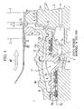
- Fig. 4 is a partial cross-sectional view showing the flow path of bleed air to the first stage unit.
- a compressor which would be to the left on the page but is not shown in the figure, is coaxially disposed to the gas turbine.
- the numerals 1 and 2 indicate first stage moving blades and first stage stationary blades, respectively.
- a plurality of first stage moving blades 1 are disposed in a circle around rotor disk 3 which is coaxial to the compressor.
- First stage moving blades 1 receive combustion gas HF from the compressor, and thereby turn first stage rotor disk 3.
- a plurality of first stage stationary blades 2 are disposed in a circle on the interior side of a vehicle so as to be coaxial to first stage rotor disk 3.
- First stage moving blades 1, first stage rotor disk 3 and first stage stationary blades 2 are provided in this way to form a first stage unit 4.
- a seal disk 7 is connected to the same shaft upstream from first stage unit 4.
- a plurality of disk holes 7a which are penetrating holes through which bleed air from upstream passes to first stage unit 4, are formed centered about this shaft and at equal angle intervals from one another.
- the numeral 5 in Fig. 4 is a bleeding chamber that takes up cooled bleed air f1 from the cooling device.
- Bleed air f1 which has been taken up into bleed air chamber 5 passes through disk holes 7a in seal disk 7, and is supplied into first stage rotor disk 3. This bleed air f1 is guided into each first stage moving blade and cools these blades from the inside.
- a plurality of tangential on board injection (TOBI) nozzles 10 are formed centered around the aforementioned shaft at the discharge port of bleeding chamber 5.
- Bleed air f1 is ejected along the direction of rotation of seal disk 7.
- the symbol f2 in Fig. 4 is sealing air from the compressor. After passing through labyrinths 8a, 8b, 8c and brass seal 9, this sealing air f2 crosses in front of the discharge port of each TOBI nozzle 10, passes through brass seal 12 and labyrinths 13a, 13b, and is supplied into space interval C between first stage moving blades 1 and first stage stationary blades 2.
- the sealing air f2 supplied to space interval C prevents combustion gas HF from leaking inside via this space interval C.
- sealing air f2 on its way from the compressor to space interval C interferes with the swirling flow of bleed air f1 discharged from each TOBI nozzle 10 toward seal disk 7. For this reason, the circumferential speed component is reduced. The reduction in this circumferential speed component invites an increase in pumping losses. As a result, the effect of providing the TOBI nozzles 10 is lost. In other words, the gas turbine looses power.
- the present invention was conceived in view of the above-described circumstances and has as its objective the provision of a gas turbine for a design in which bleed air is supplied in a swirling flow from tangential on board injection (TOBI) nozzles to a seal disk, wherein this gas turbine can effectively improve power from the swirling flow.
- TOBI tangential on board injection
- the present invention employs a gas turbine comprising the features of claim 1 to resolve the above-described problems.
- the above-described gas turbine is designed so that the sealing air which is directed toward the area between the stationary blades and the moving blades flows through the sealing air bypass flow path.
- the swirling flow which was discharged from the first TOBI nozzle is not subject to interference from the sealing air.
- the swirling flow is supplied to the disk holes with its circumferential speed component maintained, so that the rotational power of the seal disk is assisted by the swirling flow and the rotation of the seal disk is accelerated.
- the gas turbine's power can be increased.
- a second TOBI nozzle is provided which takes up a portion of the bleed air to form swirling flow, and controls the flow rate of sealing air to the sealing air bypass flow path.
- the swirling flow by the first TOBI nozzle decreases the static pressure at the discharge port of the first TOBI nozzie and reduces the flow rate at which the sealing air is provided.
- the gas turbine of the present embodiment is equipped with a first stage unit 30 which has first stage stationary blades 31 (stationary blades) disposed in a circle on the interior side of a casing; first stage rotor disk 32 (rotor disk) adjacent to these first stage stationary blades 31; and first stage moving blades 33 (moving blades) disposed in a circle around first stage rotor disk 32.
- first stage stationary blades 31 stationary blades
- first stage rotor disk 32 rotor disk
- first stage moving blades 33 moving blades
- a plurality of first stage moving blades 33 are disposed around first stage rotor disk 32. By receiving the combustion gas from a combustion chamber, not pictured in the figures, this first stage rotor disk 33 undergoes rotational driving. Furthermore, a plurality of first stage stationary blades 31 are disposed internally on the interior side of a casing so as to be coaxial to first stage rotor disk 32.
- each stage including first stage rotor disk 32, are coaxially stacked to form a single rotor, which is coaxially connected via seal disk 34 and connecting rotor 35 to the rotor for the compressor (not shown) that is disposed upstream.
- the numeral 36 in Fig. 1 indicates a bleeding chamber for taking up bleed air discharged from the compressor after its been cooled by passing through a cooling device (not shown).
- Bleeding chamber 36 is formed as a circular space between a first partitioning wall 37, which is fixed to the inner peripheral side of inner shroud 31a of each first stage stationary blade 31, and a second partitioning wall 38 which is further held by the inner peripheral side of first partitioning wall 37.
- a plurality of bleed air introducing holes are formed in first partitioning wall 37 centered about the axis of rotation of each rotor disk. These bleed air introducing holes are for introducing bleed air F1 from the cooling device into bleeding chamber 36.
- Second partitioning wall 38 is a circular component coaxially disposed around seal disk 34 and connecting rotor 35. This second partitioning wall 38 maintains the inside of first partitioning wall 37 in a stationary state.
- a plurality of tangential on board injection (TOBI) nozzles 39 are disposed in a circle centered along the width direction (axial direction) of the inner peripheral surface of second partitioning wall 38.
- Brass seals 40, 41 and labyrinth seal 42 are fixed in place at positions further upstream than the position of each TOBI nozzle 39 on the inner peripheral surface of second partitioning wall 38.
- TOBI nozzle 43 (second TOBI nozzle) is fixed in place at a position further upstream than TOBI nozzle 39 for taking up a portion of the bleed air F1 inside bleeding chamber 36 and forming swirling flow and blowing it toward the outer peripheral surface of connecting rotor 35.
- brass seal 44 and a pair of labyrinth seals 45, 46 are fixed in place to positions further downstream than each TOBI nozzle 39 on the inner peripheral surface of second partitioning wall 38.
- Seal disk 34 is a rotor disk that is provided and connected between first stage rotor disk 32 and connecting rotor 35.
- a plurality of disk holes 34a are formed in a circumferential direction centered on the rotor disk's axis of rotation at equal angular distances from one another. The position of these disk holes 34a in the radial direction centered on the axis of rotation coincides with the center of the discharge port of each TOBI nozzle 39, with disk holes 34a forming penetrating holes which are parallel to the axis of rotation.
- Bleed air F1 which has passed through these disk holes 34a passes through the disk holes formed in the rotor disks of each subsequent stage beyond first stage unit 30, and then passes through the moving blades of these later stages, cooling them from the inside.
- a portion of bleed air F1 which has passed through disk holes 34a passes through radial holes 32a in first stage rotor disk 32, and is then guided into the flow path (not shown) that is formed inside first stage moving blades 33, cooling first stage moving blades 33.
- a portion of the bleed air F1 after passing through each disk hole 34a is passed though disk hole 32b of first stage rotor disk 32 and employed in the cooling of the second and subsequent stage units (not shown).
- Radial holes 32a are a plurality of flow paths formed in the radial direction of first stage rotor disk 32. Radial holes 32a are formed centered about the axis of first stage rotor disk 32 at equal angle intervals from one another. Furthermore, the flow rate of bleed air F1 that passes through radial holes 32a and is directed at each of first stage moving blades 33 is adjusted to a constant rate using orifice plates 32c provided to the first stage rotor disk 32. A plurality of orifices, not shown, are provided in orifice plate 32c and are for carrying out flow rate adjustment. In this embodiment, since bleed air F1 is provided as a swirling flow, supply pressure of bleed air F1 is low.
- the diameter of the orifice openings is made larger than that of the conventional designs (as necessary, orifice plate 32c may be omitted).
- the hole diameter of radial holes 32a may be made larger than that of the conventional designs.
- each disk hole 32b in the radial direction centered on the axis of rotation of first stage rotor disk 32 coincides with the center of each radial hole 32a, with disk holes 32b forming penetrating holes that are parallel to the axis of rotation. Similar disk holes are formed in the rotor disks of subsequent stages, with the hole diameters differing at each stage. As a result, the air bleed F1 flow rate for cooling which is supplied to the moving blades is automatically adjusted.
- the symbol S indicates sealing air which is used to prevent combustion gas from entering internally via the space interval between first stage moving blades 33 and first stage stationary blades 31.
- Sealing air S is supplied from a compressor. Sealing air S traverses a sealing air supply flow path 50 which communicates with the discharge port of each TOBI nozzle 39 and is for supplying sealing air S to the aforementioned space interval.
- This sealing air supply flow path 50 is formed by providing a space interval flow path formed between the outer peripheral surface of sealing disk 34 and the inner peripheral surface of second partitioning wall 38, and a space interval flow path formed between first stage rotor disk 32 and first stage partitioning wall 37.
- the gas turbine according to this embodiment is characterized in the provision of a sealing air bypass flow path 55, which provides sealing air S to sealing air supply flow path 50 by bypassing the flow path between the discharge port of each TOBI nozzle 39 and each disk hole 32b opposite these discharge ports; and a double layer sealing structure 56 that is disposed to the space between first stage moving blades 33 and first stage stationary blades 31.
- Sealing air bypass flow path 55 is a pipe for taking up sealing air S, supplied from the compressor, after it has passed through TOBI nozzle 43, brass seal 40 and labyrinth seal 42, and guiding it though sealing air supply flow path 50.
- a plurality of sealing air bypass flow paths 55 are disposed centered about the axis of rotation of seal disk 34 at equal angle intervals from one another.
- double layer sealing structure 56 is formed by providing two projections 56a, 56b that are formed to the upstream edge of inner shroud 33a on the first stage moving blades 33, and two sealing members 56c, 56d that slide against projections 56a, 56b respectively and are fixed in place on the first stage partitioning wall 37 side.
- Sealing member 56c is fixed in place to the downstream edge of inner shroud 31 a.
- Sealing member 56d is fixed in place to the downstream edge of first partitioning wall 37. and are fixed in place on the first stage space 37 side.
- Sealing members 56c, 56d and projections 56a, 56b are alternately disposed so as to engage with one another, to form a plurality of curved flow paths.
- These curved flow paths are double layer structures consisting of a first stage sealing structure formed of projection 56b and sealing member 56d and a second stage sealing structure formed of projection 56a and sealing member 56c. As compared to a single layer sealing structure, this double layer sealing structure can effectively seal a space interval even with sealing air S which has a low flow rate.
- the gas turbine according to this embodiment is also characterized in the provision of a TOBI nozzle 43.
- this TOBI nozzle 43 is provided in second partitioning wall 38 so as to connect bleed air chamber 36 and a sealing air S bypass flow path formed between the outer peripheral surface of connecting rotor 35 and the inner peripheral surface of second partitioning wall 38.
- a plurality of TOBI nozzles 43 are disposed at equal angle intervals from one another centered on the axis of rotation of connecting rotor 35.
- a portion of the bleed air F1 taken up inside bleed air chamber 36 is accelerated by reducing its area, and is ejected toward the outer peripheral surface of connecting rotor 35.
- Bleed air F1 ejected in this way forms a ring-shaped swirling flow around connecting rotor 35.
- the flow rate of sealing air S which comes from the compressor, passes through this swirling flow and is directed toward sealing air bypass flow paths 55, can be controlled and prevented from becoming excessively large.
- bleed air F1 The flow of bleed air F1 will first be explained.
- Bleed air F1 which has been taken up inside bleed air chamber 36 forms a swirling flow by traveling through TOBI nozzles 39, and is ejected to sealing disk 34 in this state.
- Bleed air F1 ejected in this way forms a swirling flow that rotates in the same direction as the direction of rotation of sealing disk 34.
- sealing air S assists and accelerates the rotating power of sealing disk 34 when it passes through disk holes 34a.
- the flow area of a portion of the bleed air F1 that has passed through each disk hole 34a is reduced when traveling through orifice plate 32c after passing through radial holes 32a, and is supplied inside first stage moving blades 33 as cooling flow.
- the flow of bleed air F1 that has passed through disk holes 32b is supplied for cooling of moving blades in subsequent stages.
- the bleed air F1 that was ejected from each TOBI nozzle 43 after being taken up inside bleed air chamber 36 forms a swirling flow that turns in the same direction around connecting rotor 35 and prevents the flow rate of sealing air S from becoming too large.
- sealing air S Once sealing air S from the compressor has been held to a suitable rate using the swirling flow ejected from each TOBI nozzle 43, it passes through brass seal 40 and labyrinth seal 42, and is guided into sealing air bypass flow paths 55.
- Sealing air S ejected from these sealing air bypass flow paths 55 passes through brass seal 44 and labyrinths 45, 46, is introduced into sealing air supply flow path 50, and is supplied to the space interval between first stage moving blades 33 and first stage stationary blades 31, thereby sealing the space.
- a design is employed that is provided with sealing air bypass flow paths 55, for supplying sealing air S to sealing air supply flow path 50 by bypassing the flow paths between TOBI nozzles 39 and disk holes 34a, and a double sealing structure 56 which is disposed in the space interval between first stage stationary blades 31 and first stage moving blades 33.
- the swirling flow which is ejected from TOBI nozzles 39 at disk holes 34a does not experience interference from sealing air S.
- the swirling flow's circumferential speed component is maintained.
- the swirling flow effectively functions as a drive source for turning seal disk 34 even faster, so that the gas turbine's power can be increased.
- the gas turbine according to this embodiment employs a design in which TOBI nozzles 43 are provided which take up a portion of bleed air F1, form it into swirling flow, and control the flow rate of sealing air S at sealing air bypass flow path 55.
- TOBI nozzles 43 are provided which take up a portion of bleed air F1, form it into swirling flow, and control the flow rate of sealing air S at sealing air bypass flow path 55.
- the flow rate of sealing air S can be prevented from becoming excessively large. Accordingly, the rotating efficiency of the gas turbine can be even further improved.
Landscapes
- Engineering & Computer Science (AREA)
- Mechanical Engineering (AREA)
- General Engineering & Computer Science (AREA)
- Chemical & Material Sciences (AREA)
- Combustion & Propulsion (AREA)
- Turbine Rotor Nozzle Sealing (AREA)
Claims (2)
- Eine Gasturbine mit:einer Vielzahl von Leitschaufeln (31), die in einem Kreis an einer Innenseite eines Gehäuses angeordnet sind,einer Vielzahl von Laufschaufeln (33), die in einem Kreis an einer Seite einer Rotorscheibe (32) angrenzend an diese Leitschaufeln (31) angeordnet sind,einer Dichtungsscheibe (34), die koaxial mit der stromaufwärtigen Seite der Rotorscheibe (32) verbunden ist,einer ersten tangentialen On-Board-Einspritzdüse ("Tangential On-Board-Injection"-TOBI)-Düse (39), die angeordnet ist, um aufgenommene Nebenluft (F1) zu der Dichtungsscheibe (34) als Wirbelstrom zuzuführen, der in derselben Richtung wie die Dichtungsscheibe (34) rotiert,einem Dichtungsluft-Zuführströmungsweg (50), der mit einem Austraganschluss der ersten TOBI-Düse (39) kommuniziert, zum Zuführen von Dichtungsluft (S) zu einem Raum zwischen den Leitschaufeln (31) und den Laufschaufeln (33),einem Scheibenloch (34a), das in der Dichtungsscheibe (34) vorgesehen ist, zum Strömen lassen des Wirbelstroms von der ersten TOBI-Düse (39), undeinem Dichtungsluft-Bypass-Strömungsweg (55), der zum Zuführen der Dichtungsluft (S) zu dem Dichtungsluft-Zuführströmungsweg (50) vorgesehen ist, indem ein Abschnitt des Dichtungsluft-Zuführströmungswegs (50) zwischen der ersten TOBI-Düse (39) und dem Scheibenloch (34a) umgangen wird,dadurch gekennzeichnet, dasseine zweite TOBI-Düse (43) an einer stromaufwärtigen Seite des Dichtungsluft-Bypass-Strömungswegs (55) vorgesehen und so angeordnet ist, dass sie einen Teil der Nebenluft (F1) aufnimmt und die Nebenluft (F1) in den Dichtungsluft-Zuführströmungsweg (50) ausstößt, um einen Wirbelstrom zu bilden, wodurch eine Strömungsmenge der Dichtungsluft (S), die durch den Wirbelstrom passiert, gesteuert wird und sie zu dem Dichtungsluft-Bypass-Strömungsweg (55) gerichtet wird.
- Die Gasturbine gemäß Anspruch 1, ferner mit einer Doppeldichtungsstruktur (56), die zwischen den Leitschaufeln (31) und den Laufschaufeln (33) vorgesehen ist, wobei die Doppeldichtungsstruktur (56) eine Dichtungsstruktur einer ersten Stufe (56d,56b), die zwischen den Leitschaufeln (31) und den Laufschaufeln (33) vorgesehen ist, und eine Dichtungsstruktur einer zweiten Stufe (56c,56a) stromab der Dichtungsstruktur der ersten Stufe (56d,56b) aufweist.
Applications Claiming Priority (3)
| Application Number | Priority Date | Filing Date | Title |
|---|---|---|---|
| US238651 | 1988-08-30 | ||
| US10/238,651 US6837676B2 (en) | 2002-09-11 | 2002-09-11 | Gas turbine |
| PCT/JP2003/011657 WO2004025086A1 (en) | 2002-09-11 | 2003-09-11 | Gas turbine sealing air supply system |
Publications (2)
| Publication Number | Publication Date |
|---|---|
| EP1537296A1 EP1537296A1 (de) | 2005-06-08 |
| EP1537296B1 true EP1537296B1 (de) | 2013-06-05 |
Family
ID=31991008
Family Applications (1)
| Application Number | Title | Priority Date | Filing Date |
|---|---|---|---|
| EP03751268.8A Revoked EP1537296B1 (de) | 2002-09-11 | 2003-09-11 | Dichtungsluftversorgungssystem in einer gasturbine |
Country Status (6)
| Country | Link |
|---|---|
| US (1) | US6837676B2 (de) |
| EP (1) | EP1537296B1 (de) |
| JP (1) | JP4146257B2 (de) |
| CN (1) | CN100381677C (de) |
| CA (1) | CA2498057C (de) |
| WO (1) | WO2004025086A1 (de) |
Cited By (2)
| Publication number | Priority date | Publication date | Assignee | Title |
|---|---|---|---|---|
| EP3006668A1 (de) | 2014-10-07 | 2016-04-13 | Siemens Aktiengesellschaft | Gasturbine mit zwei Drallzuleitungen zur Kühlung des Rotors |
| US11421597B2 (en) | 2019-10-18 | 2022-08-23 | Pratt & Whitney Canada Corp. | Tangential on-board injector (TOBI) assembly |
Families Citing this family (55)
| Publication number | Priority date | Publication date | Assignee | Title |
|---|---|---|---|---|
| DE10318852A1 (de) * | 2003-04-25 | 2004-11-11 | Rolls-Royce Deutschland Ltd & Co Kg | Hauptgaskanal-Innendichtung einer Hochdruckturbine |
| US7341429B2 (en) * | 2005-11-16 | 2008-03-11 | General Electric Company | Methods and apparatuses for cooling gas turbine engine rotor assemblies |
| US20070271930A1 (en) * | 2006-05-03 | 2007-11-29 | Mitsubishi Heavy Industries, Ltd. | Gas turbine having cooling-air transfer system |
| US7591631B2 (en) * | 2006-06-30 | 2009-09-22 | United Technologies Corporation | Flow delivery system for seals |
| US7500824B2 (en) * | 2006-08-22 | 2009-03-10 | General Electric Company | Angel wing abradable seal and sealing method |
| JP2008057416A (ja) * | 2006-08-31 | 2008-03-13 | Hitachi Ltd | 軸流タービン |
| US20080061515A1 (en) * | 2006-09-08 | 2008-03-13 | Eric Durocher | Rim seal for a gas turbine engine |
| US8167534B2 (en) * | 2006-09-14 | 2012-05-01 | Solar Turbines Inc. | Seal for a turbine engine |
| GB0620430D0 (en) * | 2006-10-14 | 2006-11-22 | Rolls Royce Plc | A flow cavity arrangement |
| JP2008180149A (ja) * | 2007-01-24 | 2008-08-07 | Mitsubishi Heavy Ind Ltd | ガスタービンの翼構造及びガスタービン |
| IL181439A0 (en) * | 2007-02-20 | 2007-07-04 | Medic Nrg Ltd | An endodontic file member |
| US8562285B2 (en) * | 2007-07-02 | 2013-10-22 | United Technologies Corporation | Angled on-board injector |
| US20090074589A1 (en) * | 2007-09-18 | 2009-03-19 | Biao Fang | Cooling Circuit for Enhancing Turbine Performance |
| US20090110548A1 (en) * | 2007-10-30 | 2009-04-30 | Pratt & Whitney Canada Corp. | Abradable rim seal for low pressure turbine stage |
| KR100911765B1 (ko) | 2008-01-07 | 2009-08-10 | 더블유비엠과학기술 주식회사 | 증기 터빈용 노즐판 |
| JP4981709B2 (ja) * | 2008-02-28 | 2012-07-25 | 三菱重工業株式会社 | ガスタービン及びディスク並びにディスクの径方向通路形成方法 |
| US8079803B2 (en) * | 2008-06-30 | 2011-12-20 | Mitsubishi Heavy Industries, Ltd. | Gas turbine and cooling air supply structure thereof |
| GB0818047D0 (en) * | 2008-10-03 | 2008-11-05 | Rolls Royce Plc | Turbine cooling system |
| JP5134570B2 (ja) * | 2009-02-23 | 2013-01-30 | 三菱重工業株式会社 | タービンの冷却構造およびガスタービン |
| JP5502340B2 (ja) * | 2009-02-25 | 2014-05-28 | 三菱重工業株式会社 | タービンの冷却構造およびガスタービン |
| US9039375B2 (en) * | 2009-09-01 | 2015-05-26 | General Electric Company | Non-axisymmetric airfoil platform shaping |
| US8578720B2 (en) | 2010-04-12 | 2013-11-12 | Siemens Energy, Inc. | Particle separator in a gas turbine engine |
| US8677766B2 (en) | 2010-04-12 | 2014-03-25 | Siemens Energy, Inc. | Radial pre-swirl assembly and cooling fluid metering structure for a gas turbine engine |
| US8613199B2 (en) | 2010-04-12 | 2013-12-24 | Siemens Energy, Inc. | Cooling fluid metering structure in a gas turbine engine |
| US8584469B2 (en) | 2010-04-12 | 2013-11-19 | Siemens Energy, Inc. | Cooling fluid pre-swirl assembly for a gas turbine engine |
| CH703827A1 (de) * | 2010-09-20 | 2012-03-30 | Alstom Technology Ltd | Gasturbinenanordnung mit einer Ringdichtungsanordnung für einen Ringraum zwischen wenigstens einer stationären Komponente und einer Rotoreinheit. |
| US9068461B2 (en) | 2011-08-18 | 2015-06-30 | Siemens Aktiengesellschaft | Turbine rotor disk inlet orifice for a turbine engine |
| US9181815B2 (en) | 2012-05-02 | 2015-11-10 | United Technologies Corporation | Shaped rim cavity wing surface |
| US9115587B2 (en) * | 2012-08-22 | 2015-08-25 | Siemens Energy, Inc. | Cooling air configuration in a gas turbine engine |
| JP5567077B2 (ja) | 2012-08-23 | 2014-08-06 | 三菱重工業株式会社 | 回転機械 |
| US9435206B2 (en) * | 2012-09-11 | 2016-09-06 | General Electric Company | Flow inducer for a gas turbine system |
| US20140130478A1 (en) * | 2012-11-09 | 2014-05-15 | General Electric Company | Gas turbomachine including a fuel pre-heat system |
| CN103899364B (zh) * | 2012-12-26 | 2015-12-02 | 中航商用航空发动机有限责任公司 | 航空发动机高压涡轮的轮缘密封结构、高压涡轮及发动机 |
| EP2754858B1 (de) | 2013-01-14 | 2015-09-16 | Alstom Technology Ltd | Anordnung zum Abdichten eines offenen Hohlraums gegen Heißgaseinschluss |
| CN103206270A (zh) * | 2013-04-25 | 2013-07-17 | 北京华清燃气轮机与煤气化联合循环工程技术有限公司 | 一种冷却燃气轮机涡轮盘及动叶片的方法 |
| WO2015160403A2 (en) | 2014-01-20 | 2015-10-22 | United Technologies Corporation | Additive manufactured non-round, septum tied, conformal high pressure tubing |
| CA2878645C (en) | 2014-01-22 | 2017-02-21 | Alfa Wassermann, Inc. | Centrifugation systems with non-contact seal assemblies |
| EP2942483B2 (de) | 2014-04-01 | 2022-09-28 | Raytheon Technologies Corporation | Belüftete bordseitige tangenzialdüse für einen gasturbinenmotor |
| US10167723B2 (en) | 2014-06-06 | 2019-01-01 | United Technologies Corporation | Thermally isolated turbine section for a gas turbine engine |
| CN105525992B (zh) | 2014-10-21 | 2020-04-14 | 联合工艺公司 | 具有增材制造整流罩的增材制造管道式换热器系统 |
| US10634054B2 (en) | 2014-10-21 | 2020-04-28 | United Technologies Corporation | Additive manufactured ducted heat exchanger |
| JP6484430B2 (ja) | 2014-11-12 | 2019-03-13 | 三菱重工業株式会社 | タービンの冷却構造及びガスタービン |
| CN104564174B (zh) * | 2014-12-29 | 2017-01-18 | 北京华清燃气轮机与煤气化联合循环工程技术有限公司 | 一种燃气轮机透平静叶弹性密封结构 |
| DE112015006063B4 (de) * | 2015-01-27 | 2023-01-19 | Mitsubishi Heavy Industries, Ltd. | Rotationsmaschine |
| CN104632413B (zh) * | 2015-01-30 | 2018-05-01 | 北京华清燃气轮机与煤气化联合循环工程技术有限公司 | 一种燃气轮机燃压缸转静密封结构 |
| CN104675447A (zh) * | 2015-01-30 | 2015-06-03 | 北京华清燃气轮机与煤气化联合循环工程技术有限公司 | 一种燃气轮机涡轮冷却气路 |
| WO2016143103A1 (ja) * | 2015-03-11 | 2016-09-15 | 株式会社 東芝 | タービン |
| RU2614909C1 (ru) * | 2015-12-17 | 2017-03-30 | Открытое акционерное общество "Уфимское моторостроительное производственное объединение" ОАО "УМПО" | Охлаждаемая турбина высокого давления |
| EP3214266A1 (de) * | 2016-03-01 | 2017-09-06 | Siemens Aktiengesellschaft | Rotor einer gasturbine mit kühlluftführung |
| US10633992B2 (en) | 2017-03-08 | 2020-04-28 | Pratt & Whitney Canada Corp. | Rim seal |
| CN108060979B (zh) * | 2017-12-19 | 2024-04-26 | 中国联合重型燃气轮机技术有限公司 | 燃气轮机及其旋流装置 |
| US10982546B2 (en) | 2018-09-19 | 2021-04-20 | General Electric Company | Flow-diverting systems for gas turbine air separator |
| CN109458229A (zh) * | 2018-12-20 | 2019-03-12 | 中国航发四川燃气涡轮研究院 | 一种带旁路引气的涡轮盘腔封严结构 |
| CN114320489A (zh) * | 2022-01-11 | 2022-04-12 | 永旭腾风新能源动力科技(北京)有限公司 | 设有气封部件的燃气轮机 |
| KR102918123B1 (ko) | 2024-02-15 | 2026-01-27 | 두산에너빌리티 주식회사 | 비-선대칭 엔드월 윤곽을 가진 터빈 블레이드 및 이를 포함하는 가스 터빈 |
Family Cites Families (15)
| Publication number | Priority date | Publication date | Assignee | Title |
|---|---|---|---|---|
| CH487337A (de) * | 1968-01-10 | 1970-03-15 | Sulzer Ag | Anordnung für den Durchtritt von Gas durch den Mantel eines hohlen Rotors |
| GB1268301A (en) * | 1970-01-13 | 1972-03-29 | Rolls Royce | Improvements in or relating to gas turbine engines |
| GB1381481A (en) * | 1971-08-26 | 1975-01-22 | Rolls Royce | Aerofoil-shaped blades |
| US3989410A (en) * | 1974-11-27 | 1976-11-02 | General Electric Company | Labyrinth seal system |
| DE2941866C2 (de) * | 1978-10-26 | 1982-08-19 | Rolls-Royce Ltd., London | Turbine für ein Gasturbinentriebwerk mit lufgekühlten Turbinenschaufeln |
| US4466239A (en) * | 1983-02-22 | 1984-08-21 | General Electric Company | Gas turbine engine with improved air cooling circuit |
| US4708588A (en) * | 1984-12-14 | 1987-11-24 | United Technologies Corporation | Turbine cooling air supply system |
| JPH03165611A (ja) | 1989-11-24 | 1991-07-17 | Matsushita Electric Ind Co Ltd | 双方向増幅器 |
| GB2251040B (en) * | 1990-12-22 | 1994-06-22 | Rolls Royce Plc | Seal arrangement |
| US5282719A (en) * | 1991-05-13 | 1994-02-01 | Alliedsignal Inc. | Quad mode fan pitch actuation system for a gas turbine engine |
| US5402636A (en) * | 1993-12-06 | 1995-04-04 | United Technologies Corporation | Anti-contamination thrust balancing system for gas turbine engines |
| JP3510320B2 (ja) | 1994-05-31 | 2004-03-29 | 三菱重工業株式会社 | ガスタービンロータの冷却空気供給装置 |
| JPH10252412A (ja) | 1997-03-12 | 1998-09-22 | Mitsubishi Heavy Ind Ltd | ガスタービンシール装置 |
| JP4067709B2 (ja) * | 1999-08-23 | 2008-03-26 | 三菱重工業株式会社 | ロータ冷却空気供給装置 |
| US6773225B2 (en) * | 2002-05-30 | 2004-08-10 | Mitsubishi Heavy Industries, Ltd. | Gas turbine and method of bleeding gas therefrom |
-
2002
- 2002-09-11 US US10/238,651 patent/US6837676B2/en not_active Expired - Lifetime
-
2003
- 2003-03-12 JP JP2003066968A patent/JP4146257B2/ja not_active Expired - Lifetime
- 2003-09-11 CA CA002498057A patent/CA2498057C/en not_active Expired - Lifetime
- 2003-09-11 CN CNB038213079A patent/CN100381677C/zh not_active Expired - Lifetime
- 2003-09-11 WO PCT/JP2003/011657 patent/WO2004025086A1/en not_active Ceased
- 2003-09-11 EP EP03751268.8A patent/EP1537296B1/de not_active Revoked
Cited By (5)
| Publication number | Priority date | Publication date | Assignee | Title |
|---|---|---|---|---|
| EP3006668A1 (de) | 2014-10-07 | 2016-04-13 | Siemens Aktiengesellschaft | Gasturbine mit zwei Drallzuleitungen zur Kühlung des Rotors |
| WO2016055354A1 (de) | 2014-10-07 | 2016-04-14 | Siemens Aktiengesellschaft | Gasturbine mit zwei drallzuleitungen zur kühlung des rotors |
| US10036256B2 (en) | 2014-10-07 | 2018-07-31 | Siemens Aktiengesellschaft | Gas turbine with two swirl supply lines for cooling the rotor |
| US11421597B2 (en) | 2019-10-18 | 2022-08-23 | Pratt & Whitney Canada Corp. | Tangential on-board injector (TOBI) assembly |
| US11815020B2 (en) | 2019-10-18 | 2023-11-14 | Pratt & Whitney Canada Corp. | Tangential on-board injector (TOBI) assembly |
Also Published As
| Publication number | Publication date |
|---|---|
| WO2004025086A1 (en) | 2004-03-25 |
| CN1682012A (zh) | 2005-10-12 |
| JP2004100686A (ja) | 2004-04-02 |
| CN100381677C (zh) | 2008-04-16 |
| EP1537296A1 (de) | 2005-06-08 |
| CA2498057C (en) | 2008-09-30 |
| US6837676B2 (en) | 2005-01-04 |
| US20040046326A1 (en) | 2004-03-11 |
| CA2498057A1 (en) | 2004-03-25 |
| JP4146257B2 (ja) | 2008-09-10 |
Similar Documents
| Publication | Publication Date | Title |
|---|---|---|
| EP1537296B1 (de) | Dichtungsluftversorgungssystem in einer gasturbine | |
| CN1322226C (zh) | 燃气轮机及从燃气轮机排放气体的方法 | |
| US6585482B1 (en) | Methods and apparatus for delivering cooling air within gas turbines | |
| US8381533B2 (en) | Direct transfer axial tangential onboard injector system (TOBI) with self-supporting seal plate | |
| JP4602518B2 (ja) | タービンにおける回転部品を冷却するための装置及び方法 | |
| JP4610710B2 (ja) | タービンホイール空洞をパージする方法と装置 | |
| US7140174B2 (en) | Methods and apparatus for assembling a gas turbine engine | |
| US7017349B2 (en) | Gas turbine and bleeding method thereof | |
| JP2015040566A (ja) | 動翼エンジェルウイングを冷却する方法およびシステム | |
| JP2016121690A (ja) | エンジンおよび前記エンジンを作動させる方法 | |
| US10619490B2 (en) | Turbine rotor blade arrangement for a gas turbine and method for the provision of sealing air in a turbine rotor blade arrangement | |
| JP2017089626A (ja) | 冷却空気転回ノズルを有するベーンを備えたガスタービンエンジン | |
| EP3358142B1 (de) | Kontrolle der spaltleckage über ein turbinenschaufeldeckband | |
| EP3044440B1 (de) | Fluidinjektor zur kühlung eines gasturbinenmotorbauteils | |
| JP3977780B2 (ja) | ガスタービン | |
| EP3486438A1 (de) | Gasturbinen mit externem kühlsystem und verfahren zur kühlung davon | |
| EP4421389B1 (de) | Luftverwirblerstruktur für kraftstoffinjektor mit geneigter strömungsführungsfläche | |
| JP6961340B2 (ja) | 回転機械 | |
| EP3653839A1 (de) | Turbinenschaufel | |
| JP2004197696A (ja) | 旋回ノズルを備えたガスタービン | |
| KR200345962Y1 (ko) | 터어보엔진의공기냉각장치 | |
| CA2568692A1 (en) | Vane platform tangential injection | |
| WO2018022059A1 (en) | Turbine engine cooling fluid feed system with fluid channels accelerating coolant tangentially to supply turbine airfoils |
Legal Events
| Date | Code | Title | Description |
|---|---|---|---|
| PUAI | Public reference made under article 153(3) epc to a published international application that has entered the european phase |
Free format text: ORIGINAL CODE: 0009012 |
|
| 17P | Request for examination filed |
Effective date: 20050309 |
|
| AK | Designated contracting states |
Kind code of ref document: A1 Designated state(s): AT BE BG CH CY CZ DE DK EE ES FI FR GB GR IE IT LI LU MC NL PT SE SI SK TR |
|
| RBV | Designated contracting states (corrected) |
Designated state(s): CH DE FR GB LI |
|
| GRAP | Despatch of communication of intention to grant a patent |
Free format text: ORIGINAL CODE: EPIDOSNIGR1 |
|
| GRAS | Grant fee paid |
Free format text: ORIGINAL CODE: EPIDOSNIGR3 |
|
| GRAA | (expected) grant |
Free format text: ORIGINAL CODE: 0009210 |
|
| RIN1 | Information on inventor provided before grant (corrected) |
Inventor name: YURI, MASANORI, C/O MITSUBISHI HEAVY INDUSTRIES, L Inventor name: LAURELLO, VINCENT, C/O MITSUBISHI POWER SYSTEMS, I Inventor name: HADA SATOSHI, C/O MITSUBISHI HEAVY INDUSTRIES, LTD |
|
| AK | Designated contracting states |
Kind code of ref document: B1 Designated state(s): CH DE FR GB LI |
|
| REG | Reference to a national code |
Ref country code: GB Ref legal event code: FG4D |
|
| REG | Reference to a national code |
Ref country code: DE Ref legal event code: R081 Ref document number: 60344225 Country of ref document: DE Owner name: MITSUBISHI HITACHI POWER SYSTEMS, LTD., YOKOHA, JP Free format text: FORMER OWNER: MITSUBISHI HEAVY INDUSTRIES, LTD., TOKYO, JP |
|
| REG | Reference to a national code |
Ref country code: CH Ref legal event code: EP |
|
| REG | Reference to a national code |
Ref country code: DE Ref legal event code: R096 Ref document number: 60344225 Country of ref document: DE Effective date: 20130801 |
|
| PLBI | Opposition filed |
Free format text: ORIGINAL CODE: 0009260 |
|
| 26 | Opposition filed |
Opponent name: SIEMENS AKTIENGESELLSCHAFT Effective date: 20140304 |
|
| PLAX | Notice of opposition and request to file observation + time limit sent |
Free format text: ORIGINAL CODE: EPIDOSNOBS2 |
|
| REG | Reference to a national code |
Ref country code: CH Ref legal event code: PL |
|
| REG | Reference to a national code |
Ref country code: DE Ref legal event code: R026 Ref document number: 60344225 Country of ref document: DE Effective date: 20140304 |
|
| GBPC | Gb: european patent ceased through non-payment of renewal fee |
Effective date: 20130911 |
|
| REG | Reference to a national code |
Ref country code: FR Ref legal event code: ST Effective date: 20140530 |
|
| PG25 | Lapsed in a contracting state [announced via postgrant information from national office to epo] |
Ref country code: LI Free format text: LAPSE BECAUSE OF NON-PAYMENT OF DUE FEES Effective date: 20130930 Ref country code: GB Free format text: LAPSE BECAUSE OF NON-PAYMENT OF DUE FEES Effective date: 20130911 Ref country code: CH Free format text: LAPSE BECAUSE OF NON-PAYMENT OF DUE FEES Effective date: 20130930 |
|
| PG25 | Lapsed in a contracting state [announced via postgrant information from national office to epo] |
Ref country code: FR Free format text: LAPSE BECAUSE OF NON-PAYMENT OF DUE FEES Effective date: 20130930 |
|
| PLAF | Information modified related to communication of a notice of opposition and request to file observations + time limit |
Free format text: ORIGINAL CODE: EPIDOSCOBS2 |
|
| PLBB | Reply of patent proprietor to notice(s) of opposition received |
Free format text: ORIGINAL CODE: EPIDOSNOBS3 |
|
| REG | Reference to a national code |
Ref country code: DE Ref legal event code: R082 Ref document number: 60344225 Country of ref document: DE Representative=s name: PATENTANWAELTE HENKEL, BREUER & PARTNER, DE Ref country code: DE Ref legal event code: R081 Ref document number: 60344225 Country of ref document: DE Owner name: MITSUBISHI HITACHI POWER SYSTEMS, LTD., YOKOHA, JP Free format text: FORMER OWNER: MITSUBISHI HEAVY INDUSTRIES, LTD., TOKYO, JP Ref country code: DE Ref legal event code: R082 Ref document number: 60344225 Country of ref document: DE Representative=s name: PATENTANWAELTE HENKEL, BREUER & PARTNER MBB, DE |
|
| PLCK | Communication despatched that opposition was rejected |
Free format text: ORIGINAL CODE: EPIDOSNREJ1 |
|
| APAH | Appeal reference modified |
Free format text: ORIGINAL CODE: EPIDOSCREFNO |
|
| APBM | Appeal reference recorded |
Free format text: ORIGINAL CODE: EPIDOSNREFNO |
|
| APBP | Date of receipt of notice of appeal recorded |
Free format text: ORIGINAL CODE: EPIDOSNNOA2O |
|
| APBQ | Date of receipt of statement of grounds of appeal recorded |
Free format text: ORIGINAL CODE: EPIDOSNNOA3O |
|
| PLAB | Opposition data, opponent's data or that of the opponent's representative modified |
Free format text: ORIGINAL CODE: 0009299OPPO |
|
| R26 | Opposition filed (corrected) |
Opponent name: SIEMENS AKTIENGESELLSCHAFT Effective date: 20140304 |
|
| REG | Reference to a national code |
Ref country code: DE Ref legal event code: R064 Ref document number: 60344225 Country of ref document: DE Ref country code: DE Ref legal event code: R103 Ref document number: 60344225 Country of ref document: DE |
|
| APBU | Appeal procedure closed |
Free format text: ORIGINAL CODE: EPIDOSNNOA9O |
|
| RDAF | Communication despatched that patent is revoked |
Free format text: ORIGINAL CODE: EPIDOSNREV1 |
|
| RDAG | Patent revoked |
Free format text: ORIGINAL CODE: 0009271 |
|
| PGFP | Annual fee paid to national office [announced via postgrant information from national office to epo] |
Ref country code: DE Payment date: 20200901 Year of fee payment: 18 |
|
| 27W | Patent revoked |
Effective date: 20200818 |