EP1536985B1 - Procede et dispositif pour identifier un impact lateral sur une automobile - Google Patents
Procede et dispositif pour identifier un impact lateral sur une automobile Download PDFInfo
- Publication number
- EP1536985B1 EP1536985B1 EP02764534A EP02764534A EP1536985B1 EP 1536985 B1 EP1536985 B1 EP 1536985B1 EP 02764534 A EP02764534 A EP 02764534A EP 02764534 A EP02764534 A EP 02764534A EP 1536985 B1 EP1536985 B1 EP 1536985B1
- Authority
- EP
- European Patent Office
- Prior art keywords
- temperature
- temperature sensor
- resistance layer
- heating
- heating device
- Prior art date
- Legal status (The legal status is an assumption and is not a legal conclusion. Google has not performed a legal analysis and makes no representation as to the accuracy of the status listed.)
- Expired - Lifetime
Links
- 238000000034 method Methods 0.000 title claims description 10
- 238000010438 heat treatment Methods 0.000 claims description 34
- 239000000758 substrate Substances 0.000 claims description 14
- 238000011156 evaluation Methods 0.000 claims description 10
- 238000005259 measurement Methods 0.000 claims description 8
- 238000011990 functional testing Methods 0.000 claims description 5
- 230000003750 conditioning effect Effects 0.000 claims description 4
- 239000000463 material Substances 0.000 claims description 2
- 239000002184 metal Substances 0.000 claims description 2
- 239000004065 semiconductor Substances 0.000 claims description 2
- 230000001419 dependent effect Effects 0.000 claims 1
- 238000012360 testing method Methods 0.000 description 12
- 239000012528 membrane Substances 0.000 description 11
- 238000001514 detection method Methods 0.000 description 7
- 230000005855 radiation Effects 0.000 description 5
- 230000001133 acceleration Effects 0.000 description 3
- 238000009529 body temperature measurement Methods 0.000 description 3
- 230000002123 temporal effect Effects 0.000 description 3
- 239000011248 coating agent Substances 0.000 description 2
- 238000000576 coating method Methods 0.000 description 2
- 230000003111 delayed effect Effects 0.000 description 2
- 239000012212 insulator Substances 0.000 description 2
- 230000002238 attenuated effect Effects 0.000 description 1
- 230000006835 compression Effects 0.000 description 1
- 238000007906 compression Methods 0.000 description 1
- 238000010276 construction Methods 0.000 description 1
- 238000011109 contamination Methods 0.000 description 1
- 230000007547 defect Effects 0.000 description 1
- 230000006735 deficit Effects 0.000 description 1
- 238000013461 design Methods 0.000 description 1
- 238000009413 insulation Methods 0.000 description 1
- 238000004519 manufacturing process Methods 0.000 description 1
- 229910052710 silicon Inorganic materials 0.000 description 1
- 239000010703 silicon Substances 0.000 description 1
- 238000012549 training Methods 0.000 description 1
Images


Classifications
-
- B—PERFORMING OPERATIONS; TRANSPORTING
- B60—VEHICLES IN GENERAL
- B60R—VEHICLES, VEHICLE FITTINGS, OR VEHICLE PARTS, NOT OTHERWISE PROVIDED FOR
- B60R21/00—Arrangements or fittings on vehicles for protecting or preventing injuries to occupants or pedestrians in case of accidents or other traffic risks
- B60R21/01—Electrical circuits for triggering passive safety arrangements, e.g. airbags, safety belt tighteners, in case of vehicle accidents or impending vehicle accidents
- B60R21/013—Electrical circuits for triggering passive safety arrangements, e.g. airbags, safety belt tighteners, in case of vehicle accidents or impending vehicle accidents including means for detecting collisions, impending collisions or roll-over
- B60R21/0136—Electrical circuits for triggering passive safety arrangements, e.g. airbags, safety belt tighteners, in case of vehicle accidents or impending vehicle accidents including means for detecting collisions, impending collisions or roll-over responsive to actual contact with an obstacle, e.g. to vehicle deformation, bumper displacement or bumper velocity relative to the vehicle
-
- B—PERFORMING OPERATIONS; TRANSPORTING
- B60—VEHICLES IN GENERAL
- B60R—VEHICLES, VEHICLE FITTINGS, OR VEHICLE PARTS, NOT OTHERWISE PROVIDED FOR
- B60R21/00—Arrangements or fittings on vehicles for protecting or preventing injuries to occupants or pedestrians in case of accidents or other traffic risks
- B60R2021/0002—Type of accident
- B60R2021/0006—Lateral collision
Definitions
- the invention relates to a method and a device for detecting a side impact on a motor vehicle.
- the detection of a side impact on a motor vehicle in the region of the passenger compartment is particularly important for the triggering of side airbags.
- various systems are known.
- acceleration sensors are attached to the doors, which directly measure the acceleration that occurs when the door is deformed.
- devices and methods are known in which a pressure sensor is mounted in a closed volume of air in the door interior and measures the reduction in air volume caused by a side impact as a pressure increase. The pressure measuring signal of the pressure sensor is checked by an evaluation device, in particular to see whether there is a sufficiently rapid pressure increase, which is detected as a side impact.
- the device according to the invention with the features of claim 1 and the method according to the invention with the features of claim 11 offer in particular the advantage that a safe and rapid detection of a side impact is ensured and still possible a self-test of the device or the method for ensuring the functionality is.
- the document WO 9511455A describes a device for detecting a side impact on a motor vehicle, with a pressure sensor provided in a closed air volume of a door interior, a provided in the closed air volume heater, and a measuring device for receiving and conditioning a measurement signal of the pressure sensor and output of a pressure signal, a heat generator for driving the heater, and an evaluation and control device for receiving the pressure signal of the measuring device and control of the heat generator.
- the subject-matter of claim 1 distinguishes Side from the list of document WO95 11455 A in that the sensor is a temperature sensor.
- the document WO9511455A further describes a method for detecting a side impact on a vehicle, in which in an enclosed air volume of a door interior, an air pressure is measured by means of an air pressure sensor and it is decided on the basis of the measured air pressure whether there is a side impact, wherein a functional test is performed at least temporarily, in which the air volume is heated and is decided from a measurement signal of the air pressure sensor, whether the air pressure sensor is functional.
- claim 11 differs from the teaching of document WO9511455A in that a temperature is measured, followed by a decision as to whether there is a side impact. In addition, a function test is carried out in which the air volume and / or the temperature sensor is heated.
- the temperature increase caused by a reduction in the air volume of the door interior in the event of a side impact is measured. Since in a side impact a sudden and thus almost adiabatic compression of the air of the air volume occurs, in which the heat energy released from the air to the door is practically negligible, a reliable side impact detection is possible.
- This occurring in a side impact temperature increase can here - unlike acceleration and pressure measuring - are simulated with relatively little effort and yet reliable in a self-test by a temperature increase is effected at least in the region of the temperature sensor via a heater. Such a self-test is advantageously possible at any time and without affecting the functionality and life of the temperature sensor.
- the measuring signal of the temperature sensor is received by a measuring device, which - possibly after a signal conditioning - passes a temperature signal to a control and evaluation unit.
- the control and evaluation unit is in turn to carry out a self-test control signals to a heat generator that controls the heater.
- the heating process and the temperature measurement can be coordinated, wherein in particular a temporal behavior and / or a Schuintenstician changed and a height and the temporal behavior of the measuring signal, in particular a time delay compared to the heating process and a slope, can be evaluated.
- the steepness and delay of the measurement signal can be detected at a sudden increase in temperature generated by a rectangular pulse.
- the temperature measurement can be done by different temperature sensors.
- resistive measurements by means of a resistance element made of a material are possible whose resistance has a high temperature coefficient.
- its surface exposed to the air volume is advantageously made large in relation to its layer thickness.
- thin layers applied to a substrate can be used.
- a thermal insulation of at least a larger portion of the measuring resistor with respect to its attachment points to increase the measurement accuracy and for a faster reaction behavior is advantageous. This can be achieved in particular by forming meander-like layers or webs on a thin region of a substrate formed as a thermally insulating membrane.
- the supply of heat energy via the heating device to the temperature sensor can be done in different ways, for example by heat conduction, convection or thermal radiation.
- heat conduction convection
- thermal radiation for a high Accuracy of the self-test on functionality is a rapid increase in temperature in the range of the temperature sensor advantageous.
- the heater When heated by heat conduction, the heater is provided on the substrate on which the temperature sensor is also applied.
- a rapid increase in temperature is achieved in particular in that the heating device is provided in the immediate vicinity of the temperature sensor on the membrane, for example as a heating resistance layer parallel to the measuring resistance layer.
- the heating resistor layer can be used as a temperature sensor.
- the supply of heat energy via heat conduction of the substrate can also be effected by a heating resistor layer provided outside the membrane, whereby a more cost-effective training is possible.
- the connection of the heater with the heat generator and the temperature sensor with the measuring device can be made possible via corresponding terminal contacts or bond pads on the chip, whereby a simple replacement of a faulty device by replacing this chip is possible.
- the supply of heat energy by convection can be done by the heater heats air, for example, as a heating resistor below the temperature sensor, the flows along the temperature sensor.
- a heat supply via thermal radiation can be done for example via a directed to the temperature sensor IR light emitting diode.
- An impairment of the functionality due to contamination or deposits on the temperature sensor can be detected as a time delay and lower measuring temperature.
- a pulse-like heating can be carried out via the heating device and thus the dynamic behavior of the temperature sensor can be checked.
- a measuring device 1 has a substrate 3 made of, for example, silicon, in which a membrane 2 is formed as a thin region by an etched depression on the underside.
- a meandering heating resistor layer 4 and a meandering temperature resistance layer 6 are provided, which are nested for effective use of the surface area of the membrane 2.
- the temperature resistance layer 6 and the Schuwiderstands Mrs 4 each consist of a thin metal layer or semiconductor layer, which are applied to an insulator layer, not shown, on the substrate 3 and the membrane 2. Outside the membrane 2, these layers - optionally with a changed thickness and width - as supply lines 8, 9 to terminal contacts or bonding pads 10, 11, 12, 13 are formed. In this case, a change in temperature can be detected as a change in the resistance between the terminal contacts 10, 11 and heat energy are supplied via the Schuwiderstandstik 6 by applying a current source or voltage source to the terminal contacts 12 and 13.
- the temperature resistance layer 6 is also formed on the membrane 2 and connected via supply lines 9 with terminal contacts 10, 11 at the edge of the chip.
- the heating device according to the invention is in this case formed by a heating resistor layer 14, which is provided on an insulator layer on the substrate 3 outside the membrane 2, also formed meander-like and connected via supply lines 8 with terminal contacts 12 and 13.
- the manufacturing cost of this measuring device are reduced compared to those of Figure 1, Fig. 2;
- the heat conduction through the thicker substrate 3 and the membrane 2 to the temperature resistance layer 6 is somewhat delayed in time, so that the temperature increase determined by the temperature resistance layer 6 due to the inertia of the thicker substrate 3 has a lower signal slope and is somewhat delayed.
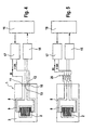
- the control and evaluation of the measuring device 1 of FIGS. 1 and 3 can be effected, for example, by means of the external circuit shown in FIG. 4 or FIG. 5.
- a temperature measurement is carried out regularly via a measuring device 15, which detects the electrical resistance between the terminal contacts 12 and 13 as a voltage drop and outputs a temperature signal to a control and evaluation device 16 by a signal conditioning.
- control and evaluation 16 is determined due to the height of the measured temperature and in particular the temporal behavior of the temperature signal, for example by forming a time derivative of the Temperaturmeßsignals and comparing with predetermined reference and threshold values, whether due to a fast, sufficiently large increase of measured temperature is a side impact, whereupon a corresponding control signal, for example is output to a side airbag or a data bus of the motor vehicle.
- the control and evaluation device 16 To carry out a self-test - for example when the motor vehicle is started or at regular time intervals - the control and evaluation device 16 outputs a control signal to a heat generator 17 which has a current or voltage source connected to the connection contacts 10 and 11 of the heating resistor layer 4 connected is. In accordance with the applied voltage UH or the current IH flowing through the heating resistor layer 4, a temperature increase of the diaphragm 2 is effected and a changed resistance value is tapped by the measuring device 15 at the connection contacts 12, 13. The control and evaluation device 16 determines the difference in the height of the temperature signal, the time delay between the output of the control signal to the heat generator 17 and the change of the temperature signal and the slope of the temperature signal.
- a self-test signal is output, for example, to a data bus of the motor vehicle, which indicates the operability of the measuring device 1; Alternatively, it is also possible to output a corresponding error signal only if a defect has been detected.
- FIG. 5 initially corresponds to that of FIG. 4, wherein via a circuit device 20, the terminals of the measuring device 15 and the heat generator 17 can be selectively connected to the terminal contacts 10, 11 or 12, 13, so that a circuit reversal compared to FIG. 4 is possible, in which the temperature resistance layer 6 serves as a heater and the Schuwiderstands harsh 4 as a temperature sensor.
- the temperature resistance layer 6 serves as a heater and the Schuwiderstands Mrs 4 as a temperature sensor.
- Such a switch can be especially for the self-test be performed by the accuracy of operation of both the temperature resistance layer 6 and the Schuwiderstandstik 4 is checked by a short-circuit reversal.
- the heating resistor layer 4 can be used as a temperature sensor, in which case no self-test is possible.
- a heating resistor 21 is connected to a heat generator, not shown, and provided outside of the substrate 3 in the air volume of the door interior.
- the arrangement of the heating resistor 21 is such that the air heated by it slides along the temperature sensor 6, which can be achieved in particular by an arrangement below and in lateral proximity to the temperature sensor 6.
- This embodiment has the advantage that an increase in temperature of the air of the air volume is achieved by serving as a heater external heating resistor 21, as it is to be measured in the event of a side impact. If the temperature sensor 6 by pollution or a coating, the temperature change is not or only attenuated or perceives with a time delay, this can be detected directly in the self-test.
- the heat is supplied via heat radiation to the temperature sensor 6, by an infrared light emitting diode (IR LED) 22 infrared radiation is radiated directly to the temperature sensor 6 via a gap 23 in the air volume of the door interior. Also in this embodiment, dirt or a coating of the temperature sensor 6 are detected by the shielding of the heat radiation as attenuation or time delay of the measured signal.
- IR LED infrared light emitting diode
Landscapes
- Engineering & Computer Science (AREA)
- Mechanical Engineering (AREA)
- Air-Conditioning For Vehicles (AREA)
- Investigating Or Analyzing Materials Using Thermal Means (AREA)
- Force Measurement Appropriate To Specific Purposes (AREA)
- Air Bags (AREA)
Claims (14)
- Dispositif de détection d'un impact latéral sur un véhicule, comprenant un capteur de température (6) prévu dans un volume d'air fermé d'un espace intérieur de portière, un dispositif de chauffage (4, 14, 21, 22) prévu dans le volume d'air fermé, et un dispositif de mesure (15) pour recevoir et conditionner un signal de mesure provenant du capteur de température (6) et pour émettre un signal de température, un générateur de chauffage (17) pour commander le dispositif de chauffage (4), et un dispositif d'exploitation et de commande (16) pour recevoir le signal de température provenant du dispositif de mesure (15) et pour commander le générateur de chauffage (17).
- Dispositif selon la revendication 1,
caractérisé en ce que
le capteur de température (6) est une couche thermo-résistante (6) en forme de méandre libre vers le volume d'air, constituée d'un matériau ayant une résistance dépendante de la température, de préférence un métal ou un semi-conducteur. - Dispositif selon la revendication 1 ou 2,
caractérisé en ce que
le capteur de température (6) est prévu sur une membrane (2) de préférence sous forme d'une zone mince d'un substrat (3). - Dispositif selon la revendication 3,
caractérisé en ce que
le dispositif de chauffage est prévu en tant que couche de résistance de chauffage (4, 14) de préférence en forme de méandre sur le substrat (3). - Dispositif selon la revendication 4,
caractérisé en ce que
la couche de résistance de chauffage (4) est formée sur la membrane (2). - Dispositif selon la revendication 5,
caractérisé en ce que
la couche thermo-résistante (6) et la couche de résistance de chauffage (4) sont appliquées sur la membrane (2) de manière emboîtée parallèlement et en forme de méandre. - Dispositif selon la revendication 6,
caractérisé en ce qu'
un dispositif de commutation (20) est prévu pour commuter entre deux états de commutation, la couche thermo-résistante (6) étant reliée, dans un premier état de commutation, au dispositif de mesure (15) tandis que la couche de résistance de chauffage (4) est reliée au générateur de chauffage (17), alors que, dans un deuxième état de commutation, la couche thermo-résistante (6) est reliée au générateur de chauffage (17) et la couche de résistance de chauffage (4) est reliée au dispositif de mesure (15). - Dispositif selon l'une des revendications 4 à 7,
caractérisé en ce que
la couche thermo-résistante (6) et la couche de résistance de chauffage (4, 14) sont reliées au dispositif de mesure (15) et au générateur de chauffage (17) par le biais de contacts de connexion (10, 11, 12, 13) prévus sur le substrat (3). - Dispositif selon l'une des revendications 1 à 3,
caractérisé en ce que
le dispositif de chauffage est un dispositif de chauffage par convection (21) disposé à l'extérieur du substrat (3) et de préférence au-dessous du capteur de température (6). - Dispositif selon l'une des revendications 1 à 3,
caractérisé en ce que
le dispositif de chauffage est un dispositif de chauffage à rayonnement thermique (22), de préférence sous forme de diode lumineuse à infrarouge, et est séparé du capteur de température (6) par un espace intermédiaire (23), dans le volume d'air. - Procédé de détection d'un impact latéral sur un véhicule, selon lequel dans un volume d'air fermé d'un espace intérieur de portière, on mesure une température au moyen d'un capteur de température (6) et sur la base de la température mesurée, on décide si l'on est en présence d'un impact latéral, un test de fonctionnement étant réalisé au moins temporairement, au cours duquel le volume d'air et/ou le capteur de température (6) est chauffé et on décide à partir d'un signal de mesure provenant du capteur de température si le capteur de température (6) est fonctionnel.
- Procédé selon la revendication 11,
caractérisé en ce que
le test de fonctionnement permet d'évaluer une hauteur, une pente et/ou un décalage temporel du signal de mesure. - Procédé selon la revendication 11 ou 12,
caractérisé en ce qu'
au cours du test de fonctionnement, on passe au moins temporairement d'un premier état de commutation, dans lequel la température est mesurée via le capteur de température (6) et de l'énergie thermique est amenée via un dispositif de chauffage (4), à un deuxième état de commutation, dans lequel la température est mesurée par le biais du dispositif de chauffage (4) et de l'énergie thermique est amenée par le biais du capteur de température (6). - Procédé selon l'une des revendications 11 à 13,
caractérisé en ce que
l'énergie thermique est amenée au moins temporairement de manière pulsée et on détermine à partir d'un comportement d'augmentation de la température si le capteur de température (6) est recouvert au moins par endroits.
Applications Claiming Priority (3)
| Application Number | Priority Date | Filing Date | Title |
|---|---|---|---|
| DE10142173A DE10142173A1 (de) | 2001-08-29 | 2001-08-29 | Verfahren und Vorrichtung zum Erkennen eines Seitenaufpralls an einem Kraftfahrzeug |
| DE10142173 | 2001-08-29 | ||
| PCT/DE2002/002792 WO2003026932A1 (fr) | 2001-08-29 | 2002-07-30 | Procede et dispositif pour identifier un impact lateral sur une automobile |
Publications (2)
| Publication Number | Publication Date |
|---|---|
| EP1536985A1 EP1536985A1 (fr) | 2005-06-08 |
| EP1536985B1 true EP1536985B1 (fr) | 2006-05-10 |
Family
ID=7696893
Family Applications (1)
| Application Number | Title | Priority Date | Filing Date |
|---|---|---|---|
| EP02764534A Expired - Lifetime EP1536985B1 (fr) | 2001-08-29 | 2002-07-30 | Procede et dispositif pour identifier un impact lateral sur une automobile |
Country Status (5)
| Country | Link |
|---|---|
| US (1) | US20040112663A1 (fr) |
| EP (1) | EP1536985B1 (fr) |
| JP (1) | JP2005502899A (fr) |
| DE (2) | DE10142173A1 (fr) |
| WO (1) | WO2003026932A1 (fr) |
Families Citing this family (8)
| Publication number | Priority date | Publication date | Assignee | Title |
|---|---|---|---|---|
| DE10065723A1 (de) * | 2000-12-29 | 2002-07-04 | Bosch Gmbh Robert | Anordnung zur Temperaturmessung und -regelung |
| US7131766B2 (en) * | 2003-07-16 | 2006-11-07 | Delphi Technologies, Inc. | Temperature sensor apparatus and method |
| US7331415B2 (en) | 2005-09-28 | 2008-02-19 | Delphi Technologies, Inc. | Pedestrian impact sensing apparatus for a vehicle bumper |
| JP2007137333A (ja) * | 2005-11-21 | 2007-06-07 | Denso Corp | 車両用乗員保護装置 |
| JP5144169B2 (ja) * | 2007-08-17 | 2013-02-13 | 本田技研工業株式会社 | コージェネレーション装置 |
| CN101806642B (zh) * | 2010-04-09 | 2011-06-22 | 福州大学 | 基于仿真模型的电机运行三维温度场分布的虚拟测试方法 |
| WO2012114902A1 (fr) * | 2011-02-25 | 2012-08-30 | Ntn株式会社 | Automobile électrique |
| US10129932B2 (en) * | 2015-06-23 | 2018-11-13 | Ppg Industries Ohio, Inc. | Sensing element |
Family Cites Families (6)
| Publication number | Priority date | Publication date | Assignee | Title |
|---|---|---|---|---|
| EP0667822B1 (fr) * | 1992-11-11 | 1997-04-02 | Siemens Aktiengesellschaft | Unite de commande a detecteur de la pression d'air pour systeme de protection des passagers d'un vehicule |
| WO1995011455A1 (fr) * | 1993-10-20 | 1995-04-27 | Autoliv Development Ab | Appareil detecteur |
| GB2292807A (en) * | 1994-08-26 | 1996-03-06 | Autoliv Dev | Detecting unacceptable leakage from the chamber of a vehicle crash sensor arrangement |
| DE10057258C1 (de) * | 2000-11-18 | 2002-03-07 | Bosch Gmbh Robert | Vorrichtung und Verfahren zur Seitenaufprallerkennung |
| DE10144266C1 (de) * | 2001-09-08 | 2003-04-03 | Bosch Gmbh Robert | Vorrichtung zur Seitenaufprallerkennung in einem Fahrzeug |
| DE10210925A1 (de) * | 2002-03-13 | 2003-10-02 | Bosch Gmbh Robert | Verfahren zur Überprüfung der Funktionsfähigkeit eines Drucksensors |
-
2001
- 2001-08-29 DE DE10142173A patent/DE10142173A1/de not_active Withdrawn
-
2002
- 2002-07-30 JP JP2003530538A patent/JP2005502899A/ja active Pending
- 2002-07-30 WO PCT/DE2002/002792 patent/WO2003026932A1/fr not_active Ceased
- 2002-07-30 US US10/415,543 patent/US20040112663A1/en not_active Abandoned
- 2002-07-30 EP EP02764534A patent/EP1536985B1/fr not_active Expired - Lifetime
- 2002-07-30 DE DE50206771T patent/DE50206771D1/de not_active Expired - Lifetime
Also Published As
| Publication number | Publication date |
|---|---|
| WO2003026932A1 (fr) | 2003-04-03 |
| US20040112663A1 (en) | 2004-06-17 |
| JP2005502899A (ja) | 2005-01-27 |
| EP1536985A1 (fr) | 2005-06-08 |
| DE50206771D1 (de) | 2006-06-14 |
| DE10142173A1 (de) | 2003-03-20 |
Similar Documents
| Publication | Publication Date | Title |
|---|---|---|
| EP0898159B1 (fr) | Système de capteur, procédé de fabrication et procédé d'autocontrôle | |
| EP1343661B1 (fr) | Dispositif et procede de reconnaissance de choc lateral | |
| EP0891898B1 (fr) | Méthode et appareillage d' enregistrement de différents paramètres d' une personne assise sur un support | |
| EP1536985B1 (fr) | Procede et dispositif pour identifier un impact lateral sur une automobile | |
| EP2542902B1 (fr) | Composant électronique, capteur de courant | |
| EP0344869A1 (fr) | Circuit de régulation pour chauffage électrique de siège, en particulier pour automobiles | |
| EP2020340A1 (fr) | Dispositif de déclenchement pour un dispositif de sécurité dans un véhicule | |
| EP1361089B1 (fr) | Procédé et dispositif de contrôle de la température d'un élément chauffant électrique | |
| EP1521972A1 (fr) | Capteur thermique pour detecter une acceleration ou un choc, comportant une unite de chauffage, et procede associe | |
| DE102009012500A1 (de) | Wärmestrommessgerät umfassend Dioden | |
| DE102010003125A1 (de) | Vorrichtung zur Temperaturmessung | |
| DE102007034321A1 (de) | Vorrichtung zum Erfassen der Windverhältnisse an einem Fahrzeug | |
| WO2020078834A1 (fr) | Procédé et capteur de batterie de détection d'incendie dans un véhicule, et véhicule | |
| DE102009019774B4 (de) | Verfahren zur thermischen Überwachung von Ausfallprozessen | |
| EP1879005B1 (fr) | Procédé destiné à la vérification d'un capteur de température doté d'au moins deux résistances sensibles à la température | |
| KR100638951B1 (ko) | 센서 엘리먼트들에 대한 전기 공급 리드의 전기 저항을 측정하는 방법 및 센서 장치 | |
| EP1021704A1 (fr) | Methode et ensemble de detecteurs pour la detection de condensation sur des surfaces | |
| DE19731717C5 (de) | Schaltung zum Zünden von zwei Zündeinheiten, insbesondere Airbag-Zündeinheiten | |
| WO2018114699A1 (fr) | Dispositif de commande utilisateur pour véhicule automobile, doté d'un capteur de force et d'un système actionneur, et procédé pour faire fonctionner ce dispositif de commande utilisateur | |
| DE102012223342A1 (de) | Vorrichtung zum Erkennen einer Sitzbelegung | |
| DE10124546C1 (de) | Temperatursensor | |
| DE10243012B4 (de) | Vorrichtung zur Wärmedetektion und Verfahren | |
| EP1726964B1 (fr) | Procédé destiné à la compensation de la dérive de température de capteurs en état monté sur place et dispositif de compensation de la dérive de température d'un capteur d'accélération d'un semi-conducteur | |
| DE102007031615A1 (de) | Verfahren zur Überprüfung eines Temperatursensors mit mindestens zwei temperatursensitiven Widerständen | |
| DE102004032585B4 (de) | Anordnung zum Steuern eines Personenschutzmittels eines Kraftfahrzeugs |
Legal Events
| Date | Code | Title | Description |
|---|---|---|---|
| PUAI | Public reference made under article 153(3) epc to a published international application that has entered the european phase |
Free format text: ORIGINAL CODE: 0009012 |
|
| 17P | Request for examination filed |
Effective date: 20040617 |
|
| AK | Designated contracting states |
Kind code of ref document: A1 Designated state(s): DE FR SE |
|
| R17P | Request for examination filed (corrected) |
Effective date: 20040329 |
|
| GRAP | Despatch of communication of intention to grant a patent |
Free format text: ORIGINAL CODE: EPIDOSNIGR1 |
|
| GRAS | Grant fee paid |
Free format text: ORIGINAL CODE: EPIDOSNIGR3 |
|
| GRAA | (expected) grant |
Free format text: ORIGINAL CODE: 0009210 |
|
| AK | Designated contracting states |
Kind code of ref document: B1 Designated state(s): DE FR SE |
|
| REF | Corresponds to: |
Ref document number: 50206771 Country of ref document: DE Date of ref document: 20060614 Kind code of ref document: P |
|
| PG25 | Lapsed in a contracting state [announced via postgrant information from national office to epo] |
Ref country code: SE Free format text: LAPSE BECAUSE OF FAILURE TO SUBMIT A TRANSLATION OF THE DESCRIPTION OR TO PAY THE FEE WITHIN THE PRESCRIBED TIME-LIMIT Effective date: 20060810 |
|
| ET | Fr: translation filed | ||
| PLBE | No opposition filed within time limit |
Free format text: ORIGINAL CODE: 0009261 |
|
| STAA | Information on the status of an ep patent application or granted ep patent |
Free format text: STATUS: NO OPPOSITION FILED WITHIN TIME LIMIT |
|
| 26N | No opposition filed |
Effective date: 20070213 |
|
| PGFP | Annual fee paid to national office [announced via postgrant information from national office to epo] |
Ref country code: FR Payment date: 20080718 Year of fee payment: 7 |
|
| REG | Reference to a national code |
Ref country code: FR Ref legal event code: ST Effective date: 20100331 |
|
| PG25 | Lapsed in a contracting state [announced via postgrant information from national office to epo] |
Ref country code: FR Free format text: LAPSE BECAUSE OF NON-PAYMENT OF DUE FEES Effective date: 20090731 |
|
| PGFP | Annual fee paid to national office [announced via postgrant information from national office to epo] |
Ref country code: DE Payment date: 20170927 Year of fee payment: 16 |
|
| REG | Reference to a national code |
Ref country code: DE Ref legal event code: R119 Ref document number: 50206771 Country of ref document: DE |
|
| PG25 | Lapsed in a contracting state [announced via postgrant information from national office to epo] |
Ref country code: DE Free format text: LAPSE BECAUSE OF NON-PAYMENT OF DUE FEES Effective date: 20190201 |