EP1536898B1 - Method for the production of a press-hardened part - Google Patents
Method for the production of a press-hardened part Download PDFInfo
- Publication number
- EP1536898B1 EP1536898B1 EP03807811A EP03807811A EP1536898B1 EP 1536898 B1 EP1536898 B1 EP 1536898B1 EP 03807811 A EP03807811 A EP 03807811A EP 03807811 A EP03807811 A EP 03807811A EP 1536898 B1 EP1536898 B1 EP 1536898B1
- Authority
- EP
- European Patent Office
- Prior art keywords
- component
- blank
- trimmed
- hot
- forming
- Prior art date
- Legal status (The legal status is an assumption and is not a legal conclusion. Google has not performed a legal analysis and makes no representation as to the accuracy of the status listed.)
- Revoked
Links
Images
Classifications
-
- C—CHEMISTRY; METALLURGY
- C21—METALLURGY OF IRON
- C21D—MODIFYING THE PHYSICAL STRUCTURE OF FERROUS METALS; GENERAL DEVICES FOR HEAT TREATMENT OF FERROUS OR NON-FERROUS METALS OR ALLOYS; MAKING METAL MALLEABLE, e.g. BY DECARBURISATION OR TEMPERING
- C21D1/00—General methods or devices for heat treatment, e.g. annealing, hardening, quenching or tempering
- C21D1/62—Quenching devices
- C21D1/673—Quenching devices for die quenching
-
- B—PERFORMING OPERATIONS; TRANSPORTING
- B21—MECHANICAL METAL-WORKING WITHOUT ESSENTIALLY REMOVING MATERIAL; PUNCHING METAL
- B21D—WORKING OR PROCESSING OF SHEET METAL OR METAL TUBES, RODS OR PROFILES WITHOUT ESSENTIALLY REMOVING MATERIAL; PUNCHING METAL
- B21D35/00—Combined processes according to or processes combined with methods covered by groups B21D1/00 - B21D31/00
-
- B—PERFORMING OPERATIONS; TRANSPORTING
- B21—MECHANICAL METAL-WORKING WITHOUT ESSENTIALLY REMOVING MATERIAL; PUNCHING METAL
- B21D—WORKING OR PROCESSING OF SHEET METAL OR METAL TUBES, RODS OR PROFILES WITHOUT ESSENTIALLY REMOVING MATERIAL; PUNCHING METAL
- B21D53/00—Making other particular articles
- B21D53/88—Making other particular articles other parts for vehicles, e.g. cowlings, mudguards
-
- C—CHEMISTRY; METALLURGY
- C21—METALLURGY OF IRON
- C21D—MODIFYING THE PHYSICAL STRUCTURE OF FERROUS METALS; GENERAL DEVICES FOR HEAT TREATMENT OF FERROUS OR NON-FERROUS METALS OR ALLOYS; MAKING METAL MALLEABLE, e.g. BY DECARBURISATION OR TEMPERING
- C21D7/00—Modifying the physical properties of iron or steel by deformation
- C21D7/13—Modifying the physical properties of iron or steel by deformation by hot working
Definitions
- the invention relates to a method for producing a metallic mold component, in particular a body component, from a semifinished product of thermoformable sheet steel.
- a blank is first cut out of a coil, which then above the microstructure transformation temperature of the steel material, above which the material structure is in the austenitic state, heated, placed in the heated state in a forming tool and formed into the desired component shape and cooled with mechanical fixation of the desired Umform gleichs, wherein a compensation or curing of the component takes place.
- the invention is therefore based on the object to improve the process flow in the manufacture of components from hot-forming sheets to the effect that the cycle time - regardless of the length of the component outer contour - can be reduced.
- the basic idea of the invention lies in the consideration that the component manufacturing process should be designed in such a way that it is possible to dispense with the procedurally complex and costly final trimming of the hardened component.
- the edge regions are therefore according to the invention already cut in the uncured state of the component and not only - as usual in hot forming usual - after the heating and curing process.
- the production process according to the invention thus provides that a blank is first cut out of a coil of a hot-workable steel sheet. From this board is then removed by means of a conventional cold forming process, e.g. formed by deep drawing, and then trimming the edge regions a component blank, which has both (approximately) the desired three-dimensional shape as well as (approximately) the desired outer contour of the finished component.
- This component blank is then heated to a temperature lying above the forming temperature of the material and transferred in the hot state in a hot-forming tool in which the component is press-hardened. In this process step, the component blank undergoes a comparatively low deformation and at the same time undergoes a targeted heat treatment in the course of which a cross-component or local hardening takes place.
- component edges are changed only slightly, so that the need for a final trimming of the component edges deleted.
- component edges are both outer Boundaries as well as inner edge areas (boundaries of breakthroughs of the component) to understand.
- the trimming of the excess edge areas thus takes place before the hot forming;
- the component blank is in a soft (uncured) state and therefore can be trimmed using conventional mechanical methods.
- the cycle times can be significantly reduced compared to the conventional process flow.
- a high quality cut edge is achieved.
- thermoforming process is used as the cold-forming process for shaping the component geometry close to the final shape (see claim 2). Since a multi-stage formability of the component blank is possible in the soft state, even complex component geometries can be formed.
- mechanical cutting means are used (see claim 3). These cutting means can be integrated into the cold forming tool, in particular in the form of folding and / or punching tools, so that the edge trimming is not carried out in a separate method step but as part of the cold forming (see claim 4).
- the finished molded component should be cooled as quickly as possible.
- the finished molded component is quenched in a tool which is cooled by means of a brine (with temperature ⁇ 0 ° C) as a coolant (see claim 5);
- a brine has a particularly high thermal conductivity and heat capacity. In this way, a particularly rapid cooling of the component can be achieved.
- a semi-finished product made of an air-hardening steel is used for the production of the component (see claim 6).
- air-hardening steels quench the component In principle no additional cooling (eg by the hot forming tool) is necessary.
- the component blank is formed in the hot forming tool to final contour and then cooled only in the hot forming tool until sufficient heat resistance, rigidity and associated dimensional stability of the component is achieved. Subsequently, the component can be removed from the hot forming tool and cooled in the air ready; the hot forming tool is thus ready for receiving another component blank.
- the cycle times in the production of hardened components can be further shortened. - If the air hardening under a protective gas, it results - in addition to this time gain - the further advantage that forms no scale on the component and thus eliminates the costly subsequent descaling (see claim 7).
- the component With such heating and heat treatment under inert gas, the component remains free from surface contamination and therefore can advantageously be subjected to surface coating directly following hot working and quenching (i.e., after cooling to a temperature below the martensite temperature) (see claim 8).
- surface coating directly following hot working and quenching (i.e., after cooling to a temperature below the martensite temperature) (see claim 8).
- corrosion-inhibiting protective layers for example by galvanizing
- the residual heat resulting from the hot forming, remaining in the component can be used directly.
- a further heat treatment of the component can be carried out by tempering.
- the heating of the trimmed component blank before hot working can be carried out in a continuous furnace (see claim 9).
- the heating is carried out inductively (see claim 10).
- Such inductive heating takes place very quickly, which is why an additional time gain in the overall process time can be achieved in this case. Due to the short heating time continues to occur during heating only a negligible scaling of the component surfaces, which is why the use of inert gas can be omitted.
- Inductive heating has particular advantages in those applications in which not the entire component, but only selected areas of the component are to be press-hardened: Then selectively - by suitable design of the inductors - only the selected areas to be cured are heated and then hot-formed Tool hardened, while the remaining, unheated areas are formed in the hot forming tool, but remain in the original ductility.
- the induction heating allows adjustment of the component properties across the sheet thickness ("soft core - hard cover layer"). In this way, locally variable strength and stiffness properties can be achieved on the finished component.
- a separate, arranged between cutting device and hot forming tool heating station - analogous to the continuous furnace - are provided.
- the inductive heating is associated with a small footprint, resulting in cost savings.
- the shape and arrangement of the inductors is matched to the shape of the trimmed component blank or the areas to be heated.
- heating may also take place in the cutting device (directly after edge trimming) or in the hot forming tool (immediately before hot working).
- the cutting device or the forming tool is provided with internal inductors, or the component is heated by means of external, correspondingly shaped inductors which are introduced after the edge trimming or before the hot forming in the open cutting device or the open hot forming tool and there be placed at the desired location of the component.
- a board 3 is used as a semifinished product 2, which is cut out of a unwound Blechcoil.
- a composite sheet may be used as a semifinished product which, as described, for example, in DE 100 49 660 A1, consists of a base sheet and at least one reinforcing sheet.
- a semi-finished a Taylored Blank which consists of several welded together sheets of different material thickness and / or different material properties.
- the semifinished product may be a three-dimensionally shaped sheet metal part produced by any forming process which is to undergo further forming and a strength / rigidity increase with the aid of the method according to the invention.
- a first process step I the board 3 - as shown in Figure la - cut from a developed and straightened portion of a coil 5 of a thermoformable sheet.
- the thermoformable material is in a "soft" (i.e., uncured) state at this time, so that the circuit board 3 can easily be cut out using conventional mechanical cutting means, such as a scissor lift 4.
- the cutting of the board 3 is advantageously carried out by means of a platinum press 6, which ensures an automated feed of the coil 5 and an automatic punching and removal of the cut-out board 3.
- the thus cut out board 3 is shown in Figure 2a in a schematic perspective view
- the cut-out blanks 3 are deposited on a stack 7 and are fed in a stacked form to a cold-forming station 8 (see FIG. 1b).
- a two-stage deep drawing tool 9 - a component blank 10 is formed.
- a predetermined, optimized material flow on the blank 3 must be ensured during the cold forming process.
- the board 3 has edge regions 11 which protrude beyond an outer contour 12 of the component 1 to be molded (indicated by dashed lines in FIG. 2 a). In these edge regions 11 controlled forces are exerted during the drawing process by hold-down 13, which cause a targeted flow of material on the board 3 and thus a high-quality drawing result.
- the component blank 10 is formed close to the final contour.
- the term "close-to-net shape” should be understood to mean that those parts of the geometry of the finished component 1 which are accompanied by a macroscopic flow of material are completely formed in the component blank 10 after the cold-forming process has been completed.
- the component blank 10 is shown in FIG. 2b.
- the near-net shape shaping can take place in a single deep-drawing step, or it can be multi-stage - for example, in the two-stage deep drawing press 9 shown in FIG. 1b.
- the component blank 10 is inserted into a cutting device 15 and cut there (process step III, FIG. 1c). Since the material of the component blank 10 is still in a "soft", ie uncured, state at this time, this cutting process can be carried out with the aid of mechanical cutting means 14 (Especially with cutting blades, folding and / or punching tools) done.
- a separate cutting device 15 may be provided for the trimming process.
- the cutting means 14 may be integrated into the last stage 9 'of the deep-drawing tool 9, so that in the last deep-drawing stage 9' in addition to the finished molding of the sheet metal blank 10, the marginal cutting occurs.
- the board 3 produces a truncated component blank 17 which is close to the final contour and which is only slightly different from the desired one in terms of its three-dimensional shape and with respect to its edge contour 12 ' Deviates component shape.
- the cut edge portions 11 are removed in the cutting device 15; the component blank 17 (FIG. 2c) is removed from the cutting device 15 by means of a manipulator 19 and fed to the next process stage.
- the trimmed component blank 17 is now subjected to hot forming, in the context of which it is formed and hardened onto the final component mold 1.
- the trimmed component blank 17 is inserted by a manipulator 20 in a continuous furnace 21, where it is heated to a temperature which is above the structural transformation temperature in the austenitic state; Depending on the steel grade, this corresponds to a heating to a temperature between 700 ° C. and 1100 ° C.
- the atmosphere of the continuous furnace 21 is rendered inert by a targeted and sufficient addition of a protective gas in order to prevent scaling of uncoated interfaces 12 'of the trimmed blanks 17 or 17. when using uncoated sheets - to prevent the entire blank surface.
- protective gas for example, carbon dioxide and / or nitrogen can be used.
- the heated trimmed component blank 17 is then inserted by means of a manipulator 22 into a hot-forming tool 23, in which the three-dimensional shape and the edge contour 12 'of the trimmed component blank 17 are brought to their final, desired level. Since the trimmed component blank 17 already has near net shape dimensions, only a slight adaptation of the shape is necessary during hot forming.
- the hot-forming tool 23 the trimmed blank 17 is finish-formed and rapidly cooled, whereby a fine-grained martensitic or bainitic material structure is set. This process step corresponds to a hardening of the component 1 and allows a targeted adjustment of the material strength. Details and various embodiments of this curing process are described for example in DE 100 49 660 A1.
- a cross-component curing of the entire component 1 can take place; alternatively, portions of the component 1 selected by a suitable shape of the hot working tool (e.g., insulating inserts, air gaps, etc.) may be recessed from hardening so that the hardening of the component 1 is only local.
- a suitable shape of the hot working tool e.g., insulating inserts, air gaps, etc.
- the component 1 is removed from the hot forming tool 23. Due to the hot-forming process upstream near-net shape trimming of the component blank 10 and the shape adaptation of the outer boundary 12 'in hot forming tool 23, the component 1 after completion of the hot forming process already the desired outer contour 24, so that no time-consuming trimming of the component edge after hot forming is.
- the component 1 is quenched in a hot-working tool cooled by brine.
- a hot-working tool cooled by brine.
- Such a brine has a high thermal conductivity and heat capacity lapped.
- the brine can be cooled to temperatures well below the freezing point of water.
- the hot forming of the component 1 is usually accompanied by a scaling of the component surface, so that the component 1 in a further process step (process step V, Figure 1e) in a dry cleaning station 25 (for example by shot peening) must be descaled.
- the cooling of the finished molded component 1 in the hot forming tool 23 now represents the bottleneck of the overall process: With hardening in the tool 23, the cooling time required overall is about 20, with good design of the tool-integrated cooling, depending on the sheet thickness, workpiece size and final temperature to 40 seconds, with the majority of cases ranging between 25 and 30 seconds.
- a shortening of the cycle time can be achieved here by using air-hardening steels as materials for the components 1:
- the component 1 in the hot forming tool 23 only needs to be cooled until sufficient heat resistance, rigidity and associated dimensional stability of the Component 1 is reached; then the component can 1 are removed from the tool 23, so that the further heat treatment process takes place in air outside of the tool 23, and the hot forming tool 23 is ready for receiving a next component blank 17.
- the residence time of the component 1 in the hot forming tool 23 can be reduced to a few ( ⁇ 10) seconds, which leads to a further reduction of the overall cycle time.
- the heating can be carried out inductively.
Description
Die Erfindung betrifft ein Verfahren zur Herstellung eines metallischen Formbauteils, insbesondere eines Karosseriebauteils, aus einem Halbzeug aus warmformbarem Stahlblech.The invention relates to a method for producing a metallic mold component, in particular a body component, from a semifinished product of thermoformable sheet steel.
Viele Bauteile, insbesondere Karosseriebauteile im Fahrzeugbau, müssen hohe Anforderungen in bezug auf Steifigkeit und Festigkeit erfüllen. Gleichzeitig sollen die Bauteile im Interesse der Gewichtsreduzierung eine möglichst geringe Materialdicke aufweisen. Um diesen beiden Anforderungen gerecht zu werden, kommen verstärkt hochfeste und höchstfeste Stahlwerkstoffe zum Einsatz, welche - je nach Zusammensetzung und Wärmebehandlung - sehr hohe Festigkeiten aufweisen. Die Herstellung von Karosseriebauteilen aus diesen höchstfesten Stahlblechen erfolgt vorzugsweise in einem Warmumformprozess, bei dem - wie beispielsweise in der DE 100 49 660 A1 oder in der DE 101 49 221 C1 beschrieben - eine Platine erwärmt und anschließend in einem speziellen Formwerkzeug geformt und gehärtet wird. Durch eine geeignete Wahl der Prozessparameter während des Warmumformens können dabei die Festigkeits- und Zähigkeitswerte des Bauteils gezielt eingestellt werden.Many components, in particular body parts in the automotive industry, must meet high requirements in terms of rigidity and strength. At the same time, the components should have the lowest possible material thickness in the interest of weight reduction. In order to meet these two requirements, increasingly high-strength and ultra-high-strength steel materials are used, which - depending on the composition and heat treatment - have very high strengths. The production of body components from these high-strength steel sheets is preferably carried out in a hot forming process, in which - as described for example in DE 100 49 660 A1 or DE 101 49 221 C1 - heated a board and then molded and cured in a special mold. By a suitable choice of the process parameters during hot forming while the strength and toughness values of the component can be adjusted specifically.
Zur Herstellung eines solchen Bauteils mit Hilfe der Warmumformung wird zunächst aus einem Coil eine Platine ausgeschnitten, die anschließend oberhalb der Gefügeumwandlungstemperatur des Stahlwerkstoffs, oberhalb derer das Werkstoffgefüge im austenitischen Zustand vorliegt, erwärmt, im erwärmten Zustand in ein Umformwerkzeug eingelegt und in die gewünschte Bauteilform umgeformt und unter mechanischer Fixierung des gewünschten Umformzustands abgekühlt, wobei eine Vergütung bzw. Härtung des Bauteils erfolgt.To produce such a component by means of hot forming, a blank is first cut out of a coil, which then above the microstructure transformation temperature of the steel material, above which the material structure is in the austenitic state, heated, placed in the heated state in a forming tool and formed into the desired component shape and cooled with mechanical fixation of the desired Umformzustands, wherein a compensation or curing of the component takes place.
Um ein auf diese Weise hergestelltes Bauteil maßhaltig zu schneiden, ist allerdings ein hoher apparativer Aufwand erforderlich: Insbesondere sind zum kalten Schneiden gehärteter Werkstoffe sehr hohe Schneidkräfte erforderlich, was zu einem schnellen Werkzeugverschleiß und hohen Instandhaltungskosten führt. Weiterhin ist das kalte Beschneiden solcher hochfester Bauteile problematisch, da beispielsweise die im kalten Zustand beschnittenen Bauteilkanten mehr oder weniger große Grate aufweisen, was aufgrund der hohen Kerbempfindlichkeit der hochfesten Werkstoffe zu einer schnellen Rissbildung im Bauteil führen kann.In order to cut a component produced in this way dimensionally stable, however, a high expenditure on equipment is required: In particular, very high cutting forces are required for cold cutting of hardened materials, which leads to rapid tool wear and high maintenance costs. Furthermore, the cold trimming of such high-strength components is problematic because, for example, the trimmed in the cold state component edges have more or less large burrs, which can lead to rapid cracking in the component due to the high notch sensitivity of high-strength materials.
Zur Vermeidung dieser beim mechanischen Beschneiden der gehärteten Bauteile auftretenden Schwierigkeiten werden vielfach alternative Schneidverfahren eingesetzt, wie zum Beispiel Laserschneiden oder Wasserstrahlschneiden. Zwar kann mit Hilfe dieser Verfahren ein qualitativ hochwertiger Beschnitt der Bauteilkante erreicht werden, jedoch arbeiten diese Schneidverfahren vergleichsweise langsam, da die Zykluszeiten hier unmittelbar von der Länge der Schnittkante sowie von den einzuhaltenden Toleranzen abhängen. Der abschließende Beschneidungsprozess stellt somit einen Flaschenhals bei der Herstellung warmumgeformter Bauteile her, der die Zahl der pro Zeiteinheit herzustellenden Bauteile begrenzt. Zwar kann die Gesamtzykluszeit der Bauteilherstellung reduziert werden, wenn - je nach Länge der Schnittkante - mehrere parallel arbeitende Laser- oder Wasserstrahlschneidanlagen bereitgestellt werden, jedoch ist dies mit hohen Zusatzinvestionen und Logistikaufwand verbunden und daher nachteilig.To avoid this occurring during mechanical trimming of the cured components difficulties many alternative cutting methods are used, such as laser cutting or water jet cutting. Although a high-quality trimming of the component edge can be achieved with the aid of these methods, these cutting methods work comparatively slowly, since the cycle times here depend directly on the length of the cut edge and on the tolerances to be maintained. The final clipping process thus creates a bottleneck in the manufacture of hot formed components which limits the number of components to be produced per unit of time. Although the total cycle time of the component production can be reduced if - depending on the length of the cutting edge - several parallel laser or water jet cutting systems are provided, but this is associated with high additional investments and logistics and therefore disadvantageous.
Der Erfindung liegt somit die Aufgabe zugrunde, den Verfahrensablauf bei der Herstellung von Bauteilen aus warmumformbaren Blechen dahingehend zu verbessern, dass die Zykluszeit - unabhängig von der Länge der Bauteilaußenkontur - reduziert werden kann.The invention is therefore based on the object to improve the process flow in the manufacture of components from hot-forming sheets to the effect that the cycle time - regardless of the length of the component outer contour - can be reduced.
Die Aufgabe wird erfindungsgemäß durch die Merkmale des Anspruchs 1 gelöst.The object is achieved by the features of claim 1.
Die Grundidee der Erfindung besteht in der Überlegung, dass der Bauteil-Herstellungsprozess in einer solchen Weise gestaltet werden sollte, dass auf die verfahrenstechnisch aufwendige und kostenintensive abschließende Beschneidung des gehärteten Bauteils verzichtet werden kann. Die Randbereiche werden daher erfindungsgemäß bereits im ungehärteten Zustand des Bauteils abgeschnitten und nicht erst - wie herkömmlicherweise beim Warmumformen üblich - nach dem Erwärmungs- und Härteprozess.The basic idea of the invention lies in the consideration that the component manufacturing process should be designed in such a way that it is possible to dispense with the procedurally complex and costly final trimming of the hardened component. The edge regions are therefore according to the invention already cut in the uncured state of the component and not only - as usual in hot forming usual - after the heating and curing process.
Der erfindungsgemäße Herstellungsprozess sieht somit vor, dass zunächst aus einem Coil aus einem warmumformbaren Stahlblech eine Platine ausgeschnitten wird. Aus dieser Platine wird anschließend mittels eines herkömmlichen Kaltumformverfahrens, z.B. durch Tiefziehen, und anschließendem Beschneiden der Randbereiche ein Bauteil-Rohling geformt, der bereits sowohl (näherungsweise) die gewünschte dreidimensionale Form als auch (näherungsweise) die gewünschte Außenkontur des fertigen Bauteils hat. Dieser Bauteil-Rohling wird anschließend auf eine oberhalb der Umformtemperatur des Werkstoffs liegende Temperatur erwärmt und im Warmzustand in ein Warmumform-Werkzeug transferiert, in dem das Bauteil pressgehärtet wird. In diesem Verfahrensschritt erfährt der Bauteil-Rohling eine vergleichsweise geringe Umformung und wird gleichzeitig einer gezielten Wärmebehandlung unterzogen, im Zuge derer eine bauteilübergreifende oder lokale Härtung erfolgt.The production process according to the invention thus provides that a blank is first cut out of a coil of a hot-workable steel sheet. From this board is then removed by means of a conventional cold forming process, e.g. formed by deep drawing, and then trimming the edge regions a component blank, which has both (approximately) the desired three-dimensional shape as well as (approximately) the desired outer contour of the finished component. This component blank is then heated to a temperature lying above the forming temperature of the material and transferred in the hot state in a hot-forming tool in which the component is press-hardened. In this process step, the component blank undergoes a comparatively low deformation and at the same time undergoes a targeted heat treatment in the course of which a cross-component or local hardening takes place.
Da der Bauteil-Rohling zu Beginn der Warmumformung bereits annähernd die gewünschten Maße aufweist, ist während der Warmumformung nur noch eine verhältnismäßig geringe Anpassung bzw. Korrektur der Bauteilkontur notwendig. Dadurch werden die Bauteilränder nur unwesentlich geändert, so dass die Notwendigkeit einer abschließenden Beschneidung der Bauteilränder entfällt. Unter "Bauteilrändern" sind hier sowohl äußere Berandungen als auch innere Randbereiche (Berandungen von Durchbrüchen des Bauteils) zu verstehen.Since the component blank already has approximately the desired dimensions at the beginning of hot forming, only a relatively small adjustment or correction of the component contour is necessary during hot forming. As a result, the component edges are changed only slightly, so that the need for a final trimming of the component edges deleted. Under "component edges" here are both outer Boundaries as well as inner edge areas (boundaries of breakthroughs of the component) to understand.
Im Gegensatz zu herkömmlichen Warmumformverfahren erfolgt bei dem erfindungsgemäßen Herstellungsverfahren das Beschneiden der überschüssigen Randbereiche somit vor der Warmumformung; zu diesem Zeitpunkt befindet sich der Bauteil-Rohling in einem weichen (ungehärteten) Zustand und kann daher mit Hilfe herkömmlicher mechanischer Verfahren beschnitten werden. Somit kann auf die aufwendige und zeitraubende Laser- bzw. Wasserstrahlbeschneidung des fertigen Pressteils verzichtet werden, so dass die Durchlaufzeiten im Vergleich zum konventionellen Prozessablauf erheblich gesenkt werden können. Gleichzeitig wird eine hochwertige Schnittkante erreicht.In contrast to conventional hot forming processes, in the production method according to the invention, the trimming of the excess edge areas thus takes place before the hot forming; At this time, the component blank is in a soft (uncured) state and therefore can be trimmed using conventional mechanical methods. Thus, can be dispensed with the laborious and time-consuming laser or Wasserstrahlbeschneidung the finished pressed part, so that the cycle times can be significantly reduced compared to the conventional process flow. At the same time, a high quality cut edge is achieved.
Weiterhin erfolgt bei Verwendung des erfindungsgemäßen Verfahrens im Warmumformwerkzeug nun noch eine geringe Umformung des Bauteils; somit kann der Werkzeugverschleiß des Warmumformwerkzeugs erheblich reduziert werden.Furthermore, when using the method according to the invention in the hot forming tool now still a small deformation of the component; Thus, the tool wear of the hot forming tool can be significantly reduced.
Da die Bauteilgeometrie (fast) vollständig durch Kaltumformung hergestellt wird, kann die Herstellung des Bauteils im Zuge der Konstruktionsphase durch konventionelle Umformsimulation abgesichert werden. Dies ermöglicht reduzierte Entwicklungskosten für Bauteil und Werkzeug.Since the component geometry is produced (almost) completely by cold forming, the manufacture of the component during the design phase can be ensured by conventional forming simulation. This enables reduced development costs for component and tool.
Besondere Vorteile lassen sich erzielen, wenn als Kaltumformungsverfahren zur endformnahen Ausformung der Bauteilgeometrie ein (mehrstufiges) Tiefziehverfahren verwendet wird (siehe Anspruch 2). Da im Weichzustand eine mehrstufige Umformbarkeit des Bauteil-Rohlings möglich ist, können auch komplexe Bauteilgeometrien ausgeformt werden. Vorteilhafterweise wird in die letzte Stufe des Tiefziehwerkzeugs mit Schneidwerkzeugen versehen, so dass die Beschneidung des Bauteil-Rohlings direkt im Kaltumformwerkzeug erfolgt.Particular advantages can be achieved if a (multi-stage) thermoforming process is used as the cold-forming process for shaping the component geometry close to the final shape (see claim 2). Since a multi-stage formability of the component blank is possible in the soft state, even complex component geometries can be formed. Advantageously, provided in the last stage of the thermoforming tool with cutting tools, so that the trimming of the component blank takes place directly in the cold forming tool.
Zur Beschneidung des Bauteil-Rohlings kommen vorzugsweise mechanische Schneidmittel zum Einsatz (siehe Anspruch 3). Diese Schneidmittel können insbesondere in Form von Abkant- und/oder Stanzwerkzeugen in das Kaltumformwerkzeug integriert sein, so dass die Randbeschneidung nicht in einem separaten Verfahrensschritt, sondern als Teil der Kaltumformung erfolgt (siehe Anspruch 4).For cutting the component blank preferably mechanical cutting means are used (see claim 3). These cutting means can be integrated into the cold forming tool, in particular in the form of folding and / or punching tools, so that the edge trimming is not carried out in a separate method step but as part of the cold forming (see claim 4).
Um die Zykluszeit des Gesamtprozesses weiter reduzieren zu können, ist es vorteilhaft, den Prozessschritt der Presshärtung des beschnittenen Bauteil-Rohlings zeitlich möglichst kurz zu gestalten, um einen möglichst hohen Durchsatz von Bauteilen pro Warmumform-Werkzeug zu gewährleisten. Hierzu sollte das fertig ausgeformte Bauteil möglichst schnell abgekühlt werden. In einer vorteilhaften Ausführungsform wird das fertig ausgeformte Bauteil in einem Werkzeug abgeschreckt, welches mit Hilfe einer Sole (mit Temperatur < 0°C) als Kühlmittel gekühlt wird (siehe Anspruch 5); eine solche Sole hat eine besonders hohe Wärmeleitfähigkeit und Wärmekapazität. Auf diese Weise kann eine besonders schnelle Kühlung des Bauteils erreicht werden.In order to be able to further reduce the cycle time of the overall process, it is advantageous to make the process step of press-hardening the trimmed component blank as short as possible in terms of time in order to ensure the highest possible throughput of components per hot-forming tool. For this purpose, the finished molded component should be cooled as quickly as possible. In an advantageous embodiment, the finished molded component is quenched in a tool which is cooled by means of a brine (with temperature <0 ° C) as a coolant (see claim 5); Such a brine has a particularly high thermal conductivity and heat capacity. In this way, a particularly rapid cooling of the component can be achieved.
Eine zusätzliche Reduktion der Zykluszeit des Gesamtprozesses lässt sich erreichen, wenn das Bauteil über mehrere Stationen (entsprechend mehreren Werkzeugsätzen) hinweg abgekühlt wird. So wird in einer ersten Station das Bauteil so weit abgeschreckt, bis die Martensit-Grenztemperatur unterschritten ist. Die Bauteilfestigkeit ist dann bereits ausreichend für einen Weitertransport zur nächsten Station (bzw. dem nächsten Werkzeug). In dieser zweiten (bzw. einer Folge von weiteren) Station wird das Bauteil dann bis auf Handtemperatur abgekühlt.An additional reduction in the cycle time of the overall process can be achieved if the component is cooled over several stations (corresponding to several tool sets). Thus, in a first station, the component is quenched until the martensite temperature has fallen below. The component strength is then already sufficient for further transport to the next station (or the next tool). In this second (or a sequence of further) station, the component is then cooled to hand temperature.
In einer vorteilhaften Ausgestaltung wird für die Herstellung des Bauteils ein Halbzeug aus einem lufthärtenden Stahl verwendet (siehe Anspruch 6). Ein Vorteil von lufthärtenden Stählen besteht darin, dass zum Abschrecken des Bauteils prinzipiell keine zusätzliche Kühlung (z.B. durch das Warmumform-Werkzeug) notwendig ist. In diesem Fall wird der Bauteil-Rohling im Warmumform-Werkzeug auf Endkontur geformt und dann nur solange im Warmumform-Werkzeug abgekühlt, bis eine ausreichende Warmfestigkeit, Steifigkeit und damit verbundene Maßhaltigkeit des Bauteils erreicht ist. Anschließend kann das Bauteil aus dem Warmumform-Werkzeug entnommen und an der Luft fertig abgekühlt werden; das Warmumform-Werkzeug steht somit für die Aufnahme eines weiteren Bauteil-Rohlings bereit. Auf diese Weise können die Zykluszeiten bei der Herstellung gehärteter Bauteile weiter verkürzt werden. - Erfolgt die Lufthärtung unter einem Schutzgas, so ergibt sich - zusätzlich zu diesem Zeitgewinn - der weitere Vorteil, dass sich auf dem Bauteil kein Zunder bildet und somit die aufwendige nachträgliche Entzunderung entfällt (siehe Anspruch 7).In an advantageous embodiment, a semi-finished product made of an air-hardening steel is used for the production of the component (see claim 6). One advantage of air-hardening steels is that they quench the component In principle no additional cooling (eg by the hot forming tool) is necessary. In this case, the component blank is formed in the hot forming tool to final contour and then cooled only in the hot forming tool until sufficient heat resistance, rigidity and associated dimensional stability of the component is achieved. Subsequently, the component can be removed from the hot forming tool and cooled in the air ready; the hot forming tool is thus ready for receiving another component blank. In this way, the cycle times in the production of hardened components can be further shortened. - If the air hardening under a protective gas, it results - in addition to this time gain - the further advantage that forms no scale on the component and thus eliminates the costly subsequent descaling (see claim 7).
Bei einer solchen Erwärmung und Wärmebehandlung unter Schutzgas bleibt das Bauteil frei von Oberflächenverschmutzungen und kann daher mit Vorteil direkt im Anschluss an die Warmumformung und Abschreckung (d.h. nach Abkühlung auf eine Temperatur unterhalb der Martensittemperatur) einer Oberflächenbeschichtung unterzogen werden (siehe Anspruch 8). Im Zuge diese Oberflächenbeschichtung können insbesondere korrosionshemmende Schutzschichten (z.B. durch Verzinken) auf die Bauteiloberfläche aufgebracht werden. Dabei kann direkt die von der Warmumformung herrührende, im Bauteil verbliebene Restwärme genutzt werden. Anschließend kann eine weitere Wärmebehandlung des Bauteils durch Anlassen erfolgen.With such heating and heat treatment under inert gas, the component remains free from surface contamination and therefore can advantageously be subjected to surface coating directly following hot working and quenching (i.e., after cooling to a temperature below the martensite temperature) (see claim 8). In the course of this surface coating, in particular corrosion-inhibiting protective layers (for example by galvanizing) can be applied to the component surface. In this case, the residual heat resulting from the hot forming, remaining in the component, can be used directly. Subsequently, a further heat treatment of the component can be carried out by tempering.
Die Erwärmung des beschnittenen Bauteil-Rohlings vor der Warmumformung kann in einem Durchlaufofen erfolgen (siehe Anspruch 9). Alternativ wird die Erwärmung induktiv durchgeführt (siehe Anspruch 10). Eine solche induktive Erwärmung erfolgt sehr schnell, weswegen in diesem Fall ein zusätzlicher Zeitgewinn in der Gesamtprozesszeit erreicht werden kann. Aufgrund der kurzen Aufheizdauer tritt weiterhin während der Erwärmung nur eine vernachlässigbare Verzunderung der Bauteiloberflächen auf, weswegen die Verwendung von Schutzgas entfallen kann. Die induktive Erwärmung hat besondere Vorteile in denjenigen Anwendungsfällen, in denen nicht das gesamte Bauteil, sondern nur ausgewählte Bereiche des Bauteils pressgehärtet werden sollen: Dann werden selektiv - durch geeignete Gestaltung der Induktoren - nur die ausgewählten, zu härtenden Bereiche erwärmt und anschließend im Warmumform-Werkzeug gehärtet, während die restlichen, unerwärmten Bereiche zwar im Warmumform-Werkzeug umgeformt werden, aber in der ursprünglichen Duktilität verbleiben. Alternativ bzw. zusätzlich ermöglicht das Induktionserwärmen eine Einstellung der Bauteileigenschaften über die Blechdicke hinweg ("weicher Kern - harte Deckschicht"). Auf diese Weise können lokal variable Festigkeits- und Steifigkeitseigenschaften auf dem fertigen Bauteil erreicht werden.The heating of the trimmed component blank before hot working can be carried out in a continuous furnace (see claim 9). Alternatively, the heating is carried out inductively (see claim 10). Such inductive heating takes place very quickly, which is why an additional time gain in the overall process time can be achieved in this case. Due to the short heating time continues to occur during heating only a negligible scaling of the component surfaces, which is why the use of inert gas can be omitted. Inductive heating has particular advantages in those applications in which not the entire component, but only selected areas of the component are to be press-hardened: Then selectively - by suitable design of the inductors - only the selected areas to be cured are heated and then hot-formed Tool hardened, while the remaining, unheated areas are formed in the hot forming tool, but remain in the original ductility. Alternatively or additionally, the induction heating allows adjustment of the component properties across the sheet thickness ("soft core - hard cover layer"). In this way, locally variable strength and stiffness properties can be achieved on the finished component.
Zur induktiven Erwärmung kann eine getrennte, zwischen Schneidvorrichtung und Warmumform-Werkzeug angeordnete Heizstation - analog zum Durchlaufofen - vorgesehen werden. Im Unterschied zu einer Erwärmung im Durchlaufofen - bei der eine gewisse Erwärmungsstrecke notwendig ist - ist die induktive Erwärmung mit einem geringen Platzbedarf verbunden, was zu Kosteneinsparungen führt. Die Form und Anordnung der Induktoren wird auf die Form des beschnittenen Bauteil-Rohlings bzw. der zu erwärmenden Bereiche abgestimmt. Alternativ zur Erwärmung in einer getrennten Heizstation kann die Erwärmung auch in der Schneidvorrichtung (direkt nach der Randbeschneidung) oder im Warmumform-Werkzeug (direkt vor der Warmumformung) erfolgen. Hierzu ist die Schneidvorrichtung bzw. das Umformwerkzeug mit internen Induktoren versehen, oder das Bauteil wird mit Hilfe von externen, entsprechend geformten Induktoren erhitzt, welche nach der Randbeschneidung bzw. vor der Warmumformung in die geöffnete Schneidvorrichtung bzw. das geöffnete Warmumform-Werkzeug eingeführt und dort an die gewünschte Stelle des Bauteils plaziert werden.For inductive heating, a separate, arranged between cutting device and hot forming tool heating station - analogous to the continuous furnace - are provided. In contrast to a heating in the continuous furnace - in which a certain heating distance is necessary - the inductive heating is associated with a small footprint, resulting in cost savings. The shape and arrangement of the inductors is matched to the shape of the trimmed component blank or the areas to be heated. As an alternative to heating in a separate heating station, heating may also take place in the cutting device (directly after edge trimming) or in the hot forming tool (immediately before hot working). For this purpose, the cutting device or the forming tool is provided with internal inductors, or the component is heated by means of external, correspondingly shaped inductors which are introduced after the edge trimming or before the hot forming in the open cutting device or the open hot forming tool and there be placed at the desired location of the component.
Im folgenden wird die Erfindung anhand eines in den Zeichnungen dargestellten Ausführungsbeispiels näher erläutert. Dabei zeigen
- Fig. 1
- ein Verfahrensschema des erfindungsgemäßen Herstellungsprozesses eines pressgehärteten Bauteils:
- Fig. 1a: Zuschneiden der Platine (Schritt I)
- Fig. 1b: Kaltumformung (Schritt II)
- Fig. 1c: Beschneiden der Ränder (Schritt III)
- Fig. 1d: Warmumformung (Schritt IV)
- Fig. 1e: Trockenreinigung (Schritt V);
- Fig. 2
- perspektivische Ansichten ausgewählter Zwischenstufen bei der Herstellung des Bauteils:
- Fig. 2a: ein Halbzeug;
- Fig. 2b: ein daraus geformter Bauteil-Rohling;
- Fig. 2c: ein beschnittener Bauteil-Rohling;
- Fig. 2d: das fertige Bauteil.
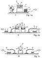
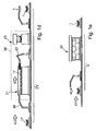
- Fig. 1
- a process diagram of the production process according to the invention of a press-hardened component:
- 1a: cutting the board (step I)
- Fig. 1b: cold forming (step II)
- Fig. 1c: trimming the edges (step III)
- Fig. 1d: hot forming (step IV)
- Fig. 1e: dry cleaning (step V);
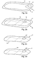
- Fig. 2
- Perspective views of selected intermediate stages in the manufacture of the component:
- Fig. 2a: a semi-finished product;
- FIG. 2b shows a component blank formed therefrom; FIG.
- Fig. 2c: a trimmed component blank;
- Fig. 2d: the finished component.
Figuren 1a bis 1e zeigen eine schematische Darstellung des erfindungsgemäßen Verfahrens zur Herstellung eines räumlich geformten, pressgehärteten Bauteils 1 aus einem Halbzeug 2. Im vorliegenden Ausführungsbeispiel wird als Halbzeug 2 eine Platine 3 verwendet, welche aus einem abgewickelten Blechcoil ausgeschnitten wird. Alternativ kann als Halbzeug ein Verbundblech zum Einsatz kommen, welches - wie z.B. in der DE 100 49 660 Al beschrieben - aus einem Basisblech und mindestens einem Verstärkungsblech besteht. Weiterhin kann als Halbzeug ein Taylored Blank verwendet werden, welches aus mehreren zusammengeschweißten Blechen unterschiedlicher Materialstärke und/oder unterschiedlicher Materialbeschaffenheit besteht. Alternativ kann das Halbzeug ein durch ein beliebiges Umformverfahren hergestelltes dreidimensional geformtes Blechteil sein, welches mit Hilfe des erfindungsgemäßen Verfahrens eine weitere Umformung sowie eine Festigkeits/Steifigkeitserhöhung erfahren soll.1a to 1e show a schematic representation of the inventive method for producing a spatially shaped, press-hardened component 1 from a
Das Halbzeug 2 besteht aus einem warmformbaren Stahl. Als Beispiel eines solchen Werkstoffs sei an dieser Stelle der unter der Handelsbezeichnung BTR 155 vertriebene lufthärtende Stahl der Firma Benteler genannt, der die nachfolgend aufgeführte Legierungszusammensetzung aufweist, wobei die zusätzlich zu dem Basismetall Eisen hinzuzufügenden Gehalte der Legierungspartner in Massenprozent zu verstehen sind:
- Kohlenstoff: 0,18 - 0,28%,
- Silizium: max. 0,7%,
- Mangan: 2,00 - 4,00%,
- Phosphor: max. 0,025%,
- Schwefel: max. 0,010%,
- Chrom: max. 0,7%,
- Molybdän: max. 0,55%,
- Nickel: max. 0,6%,
- Aluminium: 0,020 - 0,060%.
- Carbon: 0.18-0.28%,
- Silicon: max. 0.7%
- Manganese: 2.00 - 4.00%,
- Phosphor: max. 0.025%
- Sulfur: max. 0.010%
- Chrome: max. 0.7%
- Molybdenum: max. 0.55%,
- Nickel: max. 0.6%
- Aluminum: 0.020-0.060%.
In einem ersten Prozessschritt I wird die Platine 3 - wie in Figur la dargestellt - aus einem abgewickelten und geradegerichteten Abschnitt eines Coils 5 aus einem warmumformbaren Blech ausgeschnitten. Der warmumformbare Werkstoff befindet sich zu diesem Zeitpunkt in einem "weichen" (d.h. ungehärteten) Zustand, so dass die Platine 3 problemlos mit Hilfe konventioneller mechanischer Schneidmittel - beispielsweise mit Hilfe einer Hubschere 4 - ausgeschnitten werden kann. Im Großserieneinsatz erfolgt das Zuschneiden der Platine 3 vorteilhafterweise mit Hilfe einer Platinenpresse 6, welche eine automatisierte Zuführung des Coils 5 und ein automatisches Ausstanzen und Abführung der ausgeschnittenen Platine 3 gewährleistet. Die auf diese Weise ausgeschnittene Platine 3 ist in Figur 2a in einer schematischen perspektivischen Ansicht dargestelltIn a first process step I, the board 3 - as shown in Figure la - cut from a developed and straightened portion of a coil 5 of a thermoformable sheet. The thermoformable material is in a "soft" (i.e., uncured) state at this time, so that the
Die ausgeschnittenen Platinen 3 werden auf einem Stapel 7 abgelegt und werden in gestapelter Form einer Kaltumform-Station 8 zugeführt (siehe Figur 1b). Hier wird in einem zweiten Prozessschritt II aus der Platine 3 mit Hilfe des Kaltumform-Werkzeugs 8 - im vorliegenden Beispiel einem zweistufigen Tiefziehwerkzeug 9 - ein Bauteil-Rohling 10 geformt. Um dabei prozesssicher eine qualitativ hochwertige Ausformung der Bauteilgeometrie gewährleisten zu können, muss während des Kaltumformungsprozesses gezielt ein vorherbestimmter, optimierter Werkstofffluss auf der Platine 3 sichergestellt werden. Um dies zu erreichen, weist die Platine 3 Randbereiche 11 auf, die über eine (in Figur 2a gestrichelt angedeutete) Außenkontur 12 des zu formenden Bauteils 1 hinausragen. In diesen Randbereichen 11 werden während des Ziehprozesses durch Niederhalter 13 gesteuert Kräfte ausgeübt, welche einen gezielten Materialfluss auf der Platine 3 und somit ein hochqualitatives Ziehergebnis bewirken.The cut-out
Im Rahmen dieses Kaltumformprozesses (Prozessschritt II) wird der Bauteil-Rohling 10 endkonturnah ausgeformt. Unter "endkonturnah" soll dabei verstanden werden, dass diejenigen Teile der Geometrie des fertigen Bauteils 1, welche mit einem makroskopischen Materialfluss einhergehen, nach Abschluss des Kaltumformprozesses vollständig in den Bauteil-Rohling 10 eingeformt sind. Nach Abschluss des Kaltumformprozesses (Prozessschritt II) sind somit zur Herstellung der dreidimensionalen Form des Bauteils 1 nur noch geringe Formanpassungen notwendig, welche einen minimalen (lokalen) Materialfluss erfordern; der Bauteil-Rohling 10 ist in Figur 2b dargestellt.As part of this cold forming process (process step II), the component blank 10 is formed close to the final contour. The term "close-to-net shape" should be understood to mean that those parts of the geometry of the finished component 1 which are accompanied by a macroscopic flow of material are completely formed in the component blank 10 after the cold-forming process has been completed. After the completion of the cold forming process (process step II), only slight conformations of shape are required for producing the three-dimensional shape of the component 1, which require a minimal (local) material flow; the component blank 10 is shown in FIG. 2b.
Je nach Komplexität der Bauteilgeometrie kann die endkonturnahe Formgebung in einem einzigen Tiefziehschritt erfolgen, oder sie kann mehrstufig - beispielsweise in der in Figur 1b gezeigten zweistufigen Tiefziehpresse 9 - erfolgen.Depending on the complexity of the component geometry, the near-net shape shaping can take place in a single deep-drawing step, or it can be multi-stage - for example, in the two-stage
Anschließend an den Kaltumformprozess wird der Bauteil-Rohling 10 in eine Schneidvorrichtung 15 eingelegt und dort beschnitten (Prozessschritt III, Figur 1c). Da der Werkstoff des Bauteil-Rohlings 10 sich zu diesem Zeitpunkt noch in einem "weichen", d.h. ungehärteten Zustand befindet, kann dieser Beschneideprozess mit Hilfe mechanischer Schneidmittel 14 (insbesondere mit Schneidmessern, Abkant- und/oder Stanzwerkzeugen) erfolgen.Subsequent to the cold forming process, the component blank 10 is inserted into a
Für den Beschneidevorgang kann - wie in Figur 1c gezeigt - eine separate Schneidvorrichtung 15 vorgesehen sein. Alternativ können die Schneidmittel 14 in die letzte Stufe 9' des Tiefziehwerkzeugs 9 integriert sein, so dass in der letzten Tiefziehstufe 9' zusätzlich zu der Fertigformung des Blechteil-Rohlings 10 auch die randseitige Beschneidung erfolgt.For the trimming process can - as shown in Figure 1c - a
Durch den Kaltumform- und den Beschneideprozess (Prozessschritte II und III) wird somit aus der Platine 3 ein endkonturnaher beschnittener Bauteil-Rohling 17 hergestellt, der sowohl in bezug auf seine dreidimensionale Form als auch in bezug auf seine Randkontur 12' nur wenig von der gewünschten Bauteilform abweicht. Die abgeschnittenen Randbereiche 11 werden in der Schneidvorrichtung 15 abgeführt; der Bauteil-Rohling 17 (Figur 2c) wird mit Hilfe eines Manipulators 19 aus der Schneidvorrichtung 15 entnommen und der nächsten Prozessstufe zugeführt.As a result of the cold forming and the trimming process (process steps II and III), the
In der nun folgenden Prozessstufe IV (Figur 1d) wird der beschnittene Bauteil-Rohling 17 nun einer Warmumformung unterzogen, im Rahmen derer er auf die endgültige Bauteilform 1 ausgeformt und gehärtet wird. Hierzu wird der beschnittene Bauteil-Rohling 17 von einem Manipulator 20 in einen Durchlaufofen 21 eingelegt, wo er auf eine Temperatur erhitzt wird, die oberhalb der Gefügeumwandlungstemperatur in den austenitischen Zustand liegt; je nach Stahlsorte entspricht dies einer Erhitzung auf eine Temperatur zwischen 700° C und 1100° C. Vorteilhafterweise ist die Atmosphäre des Durchlaufofens 21 durch eine gezielte und ausreichende Zugabe eines Schutzgases inertisiert, um ein Verzundern nicht beschichteter Schnittstellen 12' der beschnittenen Rohlinge 17 oder - bei Verwendung unbeschichteter Bleche - an der gesamten Rohlingsoberfläche zu verhindern. Als Schutzgas kann beispielsweise Kohlendioxid und/oder Stickstoff verwendet werden.In the now following process stage IV (FIG. 1d), the trimmed component blank 17 is now subjected to hot forming, in the context of which it is formed and hardened onto the final component mold 1. For this purpose, the trimmed component blank 17 is inserted by a
Der erhitzte beschnittene Bauteil-Rohling 17 wird dann mit Hilfe eines Manipulators 22 in ein Warmumform-Werkzeug 23 eingelegt, in dem die dreidimensionale Gestalt und die Randkontur 12' des beschnittenen Bauteil-Rohlings 17 auf ihr endgültiges, gewünschtes Maß gebracht werden. Da der beschnittene Bauteil-Rohling 17 bereits endkonturnahe Maße aufweist, ist während des Warmumformung nur noch eine geringe Formanpassung notwendig. Im Warmumform-Werkzeug 23 wird der beschnittene Rohling 17 fertiggeformt und schnell abgekühlt, wodurch ein feinkörniges martensitisches oder bainitisches Werkstoffgefüge eingestellt wird. Dieser Verfahrensschritt entspricht einer Härtung des Bauteils 1 und ermöglicht eine gezielte Einstellung der Werkstofffestigkeit. Einzelheiten und verschiedene Ausgestaltungen dieses Härtungsprozesses sind beispielsweise in der DE 100 49 660 A1 beschrieben. Dabei kann eine bauteilübergreifende Härtung des gesamten Bauteils 1 erfolgen; alternativ können durch eine geeignete Gestalt des Warmumform-Werkzeugs (z.B. isolierende Einsätze, Luftspalte etc.) ausgewählte Bereiche des Bauteils 1 von der Härtung ausgespart werden, so dass die Härtung des Bauteils 1 nur lokal erfolgt.The heated trimmed component blank 17 is then inserted by means of a
Ist der gewünschte Härtungszustand des Bauteils 1 erreicht, so wird das Bauteil 1 aus dem Warmumform-Werkzeug 23 entnommen. Aufgrund der dem Warmumformungsprozess vorgelagerten endkonturnahen Beschneidung des Bauteil-Rohlings 10 sowie der Formanpassung der Außenberandung 12' im Warmumform-Werkzeug 23 weist das Bauteil 1 nach Abschluss des Warmumformprozesses bereits die gewünschte Außenkontur 24 auf, so dass nach der Warmumformung keine zeitaufwendige Beschneidung des Bauteilrandes notwendig ist.Once the desired hardening state of the component 1 has been reached, the component 1 is removed from the hot forming
Um eine schnelle Abschreckung des Bauteils 1 im Zuge der Warmumformung zu erreichen, wird das Bauteil 1 in einem durch Sole gekühlten Warmumform-Werkzeug 23 abgeschreckt. Eine solche Sole hat eine hohe Wärmeleitfähigkeit und Wärmekapazität umspült. Abhängig von den zugesetzten Salzen kann die Sole auf Temperaturen weit unterhalb des Gefrierpunktes von Wasser gekühlt werden.In order to achieve a rapid quenching of the component 1 in the course of hot forming, the component 1 is quenched in a hot-working tool cooled by brine. Such a brine has a high thermal conductivity and heat capacity lapped. Depending on the salts added, the brine can be cooled to temperatures well below the freezing point of water.
Die Warmumformung des Bauteils 1 geht im Regelfall einher mit einer Verzunderung der Bauteiloberfläche, so dass das Bauteil 1 in einem weiteren Verfahrensschritt (Prozessschritt V, Figur 1e) in einer Trockenreinigungsstation 25 (beispielsweise mittels Kugelstrahlen) entzundert werden muss.The hot forming of the component 1 is usually accompanied by a scaling of the component surface, so that the component 1 in a further process step (process step V, Figure 1e) in a dry cleaning station 25 (for example by shot peening) must be descaled.
Durch den in Figuren 1a bis 1e dargestellten Verfahrensablauf mit der endkonturnahen Beschneidung der Bauteil-Rohlinge 10 im weichen Zustand wird eine erhebliche Verkürzung der Zykluszeit gegenüber dem herkömmlichen Verfahrensablauf erreicht, bei dem das fertige, gehärtete Bauteil erst nach der Warmumformung mittels (Laser-) Schneidens auf das gewünschte Maß beschnitten wird. Wird das erfindungsgemäße Verfahren eingesetzt, so weist das Bauteil 1 nach Abschluss des Warmumformungsprozesses (Prozessschritt IV) bereits die gewünschte endgültige Außenkontur 24 auf, so dass die Hartbeschneidung - die im herkömmlichen Verfahrensablauf den Flaschenhals bildete - entfällt.The process sequence shown in FIGS. 1a to 1e with the near-net shape trimming of the
Im erfindungsgemäßen Verfahrensablauf stellt nunmehr die Abkühlung des fertig ausgeformten Bauteils 1 im Warmumform-Werkzeug 23 den Engpass des Gesamtverfahrens dar: Bei einer Härtung im Werkzeug 23 beträgt nämlich die insgesamt erforderliche Abkühlzeit bei guter Auslegung der werkzeugintegrierten Kühlung je nach Blechdicke, Werkstückgröße und Endtemperatur etwa 20 bis 40 Sekunden, wobei das Gros der Fälle im Bereich zwischen 25 und 30 Sekunden liegt. Eine Verkürzung der Zykluszeit kann hier durch den Einsatz lufthärtender Stähle als Werkstoffe für die Bauteile 1 erreicht werden: In diesem Fall braucht das Bauteil 1 im Warmumform-Werkzeug 23 nur so weit abgekühlt zu werden, bis eine ausreichende Warmfestigkeit, Steifigkeit und damit verbundene Maßhaltigkeit des Bauteils 1 erreicht ist; dann kann das Bauteil 1 aus dem Werkzeug 23 entnommen werden, so dass der weitere Wärmebehandlungsvorgang an der Luft außerhalb des Werkzeugs 23 erfolgt, und das Warmumform-Werkzeug 23 für die Aufnahme eines nächsten Bauteil-Rohlings 17 bereitsteht. Auf diese Weise kann die Verweilzeit des Bauteils 1 im Warmumform-Werkzeug 23 auf wenige (< 10) Sekunden reduziert werden, was zu einer weiteren Verkürzung der Gesamt-Zykluszeit führt.In the process sequence according to the invention, the cooling of the finished molded component 1 in the hot forming
Zusätzliche Einsparungen bzw. Reduktionen der Zykluszeit können erzielt werden, wenn nicht nur die Erwärmung der Bauteil-Rohlinge 17, sondern auch die Warmumformung in einer Schutzgasatmosphäre erfolgt; in diesem Fall ist das Umformwerkzeug 23, wie in Figur 1d gestrichelt angedeutet, in die Schutzgasatmosphäre 26 des Durchlaufofens 21 integriert. Dadurch wird ein verzunderfreier Presshärtungsprozess realisiert, so dass die ansonsten bislang notwendige nachfolgende Trockenreinigung der Bauteile 1 (Prozessschritt V) entfallen kann.Additional savings or reductions in the cycle time can be achieved if not only the heating of the
Alternativ zu der Erwärmung der Bauteil-Rohlinge 17 in dem Durchlaufofen 21 kann die Erwärmung induktiv erfolgen.As an alternative to heating the
Claims (10)
- Method of producing a metallic shaped part, in particular a vehicle body part, from a semi-finished product made of an unhardened hot-workable steel sheet, comprising the following method steps:- a part blank (10) is formed from the semi-finished product (2) by a cold-forming method, in particular a drawing method;- the part blank (10) is trimmed at the margins to a marginal contour (12') approximately corresponding to the part (1) to be produced;- the trimmed part blank (17) is heated and press-hardened in a hot-forming tool (23).
- Method according to Claim 1, characterized in that a deep-drawing method is used for shaping the part blank (10) from the semi-finished product (2).
- Method according to Claim 1 or 2, characterized in that the part blank (10) is trimmed by means of a mechanical cutting method (15).
- Method according to Claim 3, characterized in that the trimming of the part blank (10) is effected as part of the cold forming.
- Method according to one of the preceding claims, characterized in that the tool (23) is cooled with a brine.
- Method according to one of the preceding claims, characterized in that the semi-finished product (2) is made of an air-hardened steel alloy.
- Method according to the preceding claims, characterized in that the heating and hot forming of the trimmed part blank (17) are effected in an inert-gas atmosphere (26).
- Method according to Claim 7, characterized in that- the part (1) is cooled after the hot forming down to a temperature below the martensite temperature- and is provided immediately afterward with a surface coating, in particular an anti-corrosion coating.
- Method according to the preceding claims, characterized in that the heating of the trimmed part blank (17) is effected in a continuous furnace (21).
- Method according to one of Claims 1 to 8, characterized in that the heating of the trimmed part blank (17) is effected inductively.
Applications Claiming Priority (5)
| Application Number | Priority Date | Filing Date | Title |
|---|---|---|---|
| DE10242709 | 2002-09-13 | ||
| DE10242709 | 2002-09-13 | ||
| DE10254695A DE10254695B3 (en) | 2002-09-13 | 2002-11-23 | Production of a metallic component, especially a vehicle body component, from a semifinished product made of non-hardened heat-deformable sheet steel comprises cold-forming, trimming, hot-forming and press-hardening processes |
| DE10254695 | 2002-11-23 | ||
| PCT/EP2003/009607 WO2004033126A1 (en) | 2002-09-13 | 2003-08-29 | Press-hardened part and method for the production thereof |
Publications (2)
| Publication Number | Publication Date |
|---|---|
| EP1536898A1 EP1536898A1 (en) | 2005-06-08 |
| EP1536898B1 true EP1536898B1 (en) | 2006-05-31 |
Family
ID=32094615
Family Applications (1)
| Application Number | Title | Priority Date | Filing Date |
|---|---|---|---|
| EP03807811A Revoked EP1536898B1 (en) | 2002-09-13 | 2003-08-29 | Method for the production of a press-hardened part |
Country Status (5)
| Country | Link |
|---|---|
| US (1) | US7998289B2 (en) |
| EP (1) | EP1536898B1 (en) |
| JP (1) | JP4319987B2 (en) |
| DE (1) | DE50303605D1 (en) |
| WO (1) | WO2004033126A1 (en) |
Cited By (2)
| Publication number | Priority date | Publication date | Assignee | Title |
|---|---|---|---|---|
| EP2367962B1 (en) | 2008-12-19 | 2015-07-29 | voestalpine Metal Forming GmbH | Method for producing partially hardened components from sheet steel |
| DE102017201674B3 (en) | 2017-02-02 | 2018-03-29 | Ford Global Technologies, Llc | Method for producing a press-hardened component and press mold |
Families Citing this family (40)
| Publication number | Priority date | Publication date | Assignee | Title |
|---|---|---|---|---|
| DE10314115A1 (en) * | 2003-03-28 | 2004-10-14 | Audi Ag | Process for forming a sheet from a tempered steel and device for carrying out the process |
| DE10333166A1 (en) | 2003-07-22 | 2005-02-10 | Daimlerchrysler Ag | Press-hardened component and method for producing a press-hardened component |
| DE10333165A1 (en) * | 2003-07-22 | 2005-02-24 | Daimlerchrysler Ag | Production of press-quenched components, especially chassis parts, made from a semi-finished product made from sheet steel comprises molding a component blank, cutting, heating, press-quenching, and coating with a corrosion-protection layer |
| JP2005305539A (en) * | 2004-04-26 | 2005-11-04 | Nippon Steel Corp | Method for producing high strength automobile member |
| DE102005051403B3 (en) | 2005-10-25 | 2007-03-15 | Benteler Automobiltechnik Gmbh | B-column manufacturing method for motor vehicle, involves inserting mold in sectional zone of plate before or during heat formation, and cutting sectional zone after heat formation in mold |
| JP2007136534A (en) * | 2005-11-22 | 2007-06-07 | Nippon Steel Corp | Press forming apparatus and press forming method |
| JP4760338B2 (en) * | 2005-11-29 | 2011-08-31 | 日産自動車株式会社 | Material cooling method and apparatus in low temperature forming process |
| DE102007050907A1 (en) | 2007-10-23 | 2009-04-30 | Benteler Automobiltechnik Gmbh | Process for producing a hardened sheet metal profile |
| US10311519B2 (en) * | 2008-10-14 | 2019-06-04 | Interactive Brokers Llc | Computerized method and system for accumulation and distribution of securities |
| ES2350665B1 (en) * | 2008-12-02 | 2011-11-18 | Gestamp Vigo, S.A | PROCEDURE AND DEVICE FOR DETECTION OF EMBUTITION DEFECTS. |
| JP5645945B2 (en) * | 2009-11-06 | 2014-12-24 | ジョンソン コントロールズ テクノロジー カンパニーJohnson Controls Technology Company | Seat structure parts with suitable strength |
| EP2369020B1 (en) * | 2010-03-16 | 2016-10-05 | Thermission AG | Method for treating a metal element for an automobile |
| DE102010020373A1 (en) * | 2010-05-12 | 2011-11-17 | Voestalpine Stahl Gmbh | Process for producing a component from an iron-manganese steel sheet |
| DE102010049802A1 (en) * | 2010-10-27 | 2012-05-03 | Schuler Smg Gmbh & Co. Kg | Method and device for determining the hardness of a press-hardened component |
| DE102010050248B4 (en) * | 2010-11-02 | 2016-08-04 | Kirchhoff Automotive Deutschland Gmbh | Method for producing a tubular profile |
| KR101033767B1 (en) * | 2010-11-03 | 2011-05-09 | 현대하이스코 주식회사 | Automobile part manufacturing method using quenched steel sheet |
| DE102011109010A1 (en) * | 2011-07-30 | 2013-01-31 | GEDIA Gebrüder Dingerkus GmbH | Method for connecting a thermoformed part with another part made of any material |
| US9238847B2 (en) | 2011-08-05 | 2016-01-19 | Honda Motor Co., Ltd. | Tailored hardening of boron steel |
| US9089886B2 (en) | 2011-09-23 | 2015-07-28 | Thermission Ag | Method of treating a metal element for an automobile |
| KR20130043812A (en) * | 2011-10-21 | 2013-05-02 | 현대자동차주식회사 | Tail trim manufacturing method by using clad metal plate |
| KR101886074B1 (en) * | 2012-10-26 | 2018-08-08 | 현대자동차 주식회사 | Method and system for forming ultra high-tensile steel parts |
| CN103143623B (en) * | 2013-02-20 | 2016-03-30 | 安徽江淮汽车股份有限公司 | Servo punching automation production technology and device thereof |
| DE102013222242A1 (en) * | 2013-10-31 | 2015-04-30 | Magna International Inc. | Plant for the production of components with hot forming and process |
| CN103722076B (en) * | 2014-01-21 | 2016-02-17 | 东莞虹日金属科技有限公司 | A kind of automobile seat edge plate automatic production process |
| CN105916608B (en) | 2014-01-30 | 2018-11-13 | 新日铁住金株式会社 | Steel plate heating means and steel plate thermoforming device |
| DE102014006683A1 (en) | 2014-05-08 | 2015-11-12 | GM Global Technology Operations LLC (n. d. Gesetzen des Staates Delaware) | Production line for processing at least one surface component and method for processing the at least one surface component in the production line |
| WO2016016676A1 (en) * | 2014-07-30 | 2016-02-04 | ArcelorMittal Investigación y Desarrollo, S.L. | Process for manufacturing steel sheets, for press hardening, and parts obtained by means of this process |
| DE102014112755B4 (en) * | 2014-09-04 | 2018-04-05 | Thyssenkrupp Ag | Method for forming a workpiece, in particular a blank, from sheet steel |
| CN104525713B (en) * | 2014-12-16 | 2016-05-25 | 成都环龙智能系统设备有限公司 | A kind of body of a motor car punching press intellectualizing system with transfer robot |
| US10308992B2 (en) * | 2015-08-20 | 2019-06-04 | Ford Motor Company | Method and system for selectively softening hot stamped parts by induction heating |
| US10767756B2 (en) * | 2015-10-13 | 2020-09-08 | Magna Powertrain Inc. | Methods of forming components utilizing ultra-high strength steel and components formed thereby |
| US10350741B2 (en) | 2015-11-02 | 2019-07-16 | Black & Decker Inc. | Powered nail driver with a nail placement assembly |
| US11447838B2 (en) * | 2016-01-25 | 2022-09-20 | Schwartz Gmbh | Method and device for heat treating a metal component |
| DE102016002889A1 (en) * | 2016-03-09 | 2017-09-14 | GM Global Technology Operations LLC (n. d. Ges. d. Staates Delaware) | Method for avoiding edge cracks |
| US10328504B2 (en) | 2016-12-02 | 2019-06-25 | Fca Us Llc | Two-stage method of cutting ultra-high strength material sheet |
| US11014137B2 (en) | 2017-10-26 | 2021-05-25 | Ford Motor Company | Warm die trimming in hot forming applications |
| DE102018207488A1 (en) * | 2018-05-15 | 2019-11-21 | Bayerische Motoren Werke Aktiengesellschaft | Method for producing a sheet metal component |
| CN109465331B (en) * | 2018-12-29 | 2020-05-08 | 嘉善民鑫金属制品有限公司 | Needle grid manufacturing process |
| WO2023014327A2 (en) * | 2021-08-03 | 2023-02-09 | Borcelik Celik San. Tic. A.S. | A detection mechanism for determining deformation on a work piece |
| WO2023023843A1 (en) * | 2021-08-24 | 2023-03-02 | Magna International Inc. | Process for manufacturing vehicle parts |
Family Cites Families (15)
| Publication number | Priority date | Publication date | Assignee | Title |
|---|---|---|---|---|
| AT321689B (en) | 1951-04-27 | 1975-04-10 | Egyesuelt Izzolampa | Method and tool for performing stamping, graduated drawing and deep drawing from a strip material in at least four rows |
| SE435527B (en) | 1973-11-06 | 1984-10-01 | Plannja Ab | PROCEDURE FOR PREPARING A PART OF Hardened Steel |
| US5669992A (en) * | 1996-01-30 | 1997-09-23 | Bronsema; Brand | Bumper beam making process |
| DE19743802C2 (en) | 1996-10-07 | 2000-09-14 | Benteler Werke Ag | Method for producing a metallic molded component |
| SE510056C2 (en) | 1997-08-07 | 1999-04-12 | Ssab Hardtech Ab | Ways to manufacture a hardened steel detail |
| US5972134A (en) | 1997-10-02 | 1999-10-26 | Benteler Ag | Manufacture of a metallic molded structural part |
| ES2224534T3 (en) | 1999-05-12 | 2005-03-01 | Benteler Ag | METHOD FOR MANUFACTURING STRUCTURAL PARTS IN THE CONSTRUCTION OF CARS. |
| FR2807447B1 (en) | 2000-04-07 | 2002-10-11 | Usinor | METHOD FOR MAKING A PART WITH VERY HIGH MECHANICAL CHARACTERISTICS, SHAPED BY STAMPING, FROM A STRIP OF LAMINATED AND IN PARTICULAR HOT ROLLED AND COATED STEEL SHEET |
| DE10032297A1 (en) | 2000-07-03 | 2002-02-28 | C & E Fein Gmbh & Co Kg | Saw blade and method of making one |
| DE20014361U1 (en) | 2000-08-19 | 2000-10-12 | Benteler Werke Ag | B-pillar for a motor vehicle |
| DE10049660B4 (en) | 2000-10-07 | 2005-02-24 | Daimlerchrysler Ag | Method for producing locally reinforced sheet-metal formed parts |
| DE10055275A1 (en) | 2000-11-08 | 2002-05-23 | Iropa Ag | Mill annealed process to manufacture stainless steel yarn brake as a truncated cone |
| DE10149221C1 (en) | 2001-10-05 | 2002-08-08 | Benteler Automobiltechnik Gmbh | Process for producing a hardened sheet metal profile |
| DE10149220C1 (en) | 2001-10-05 | 2002-08-08 | Benteler Automobiltechnik Gmbh | Process for producing a hardened sheet metal profile |
| US6918224B2 (en) * | 2002-05-01 | 2005-07-19 | Benteler Automotive Corporation | Heat treatment strategically strengthened door beam |
-
2003
- 2003-08-29 US US10/527,721 patent/US7998289B2/en active Active
- 2003-08-29 WO PCT/EP2003/009607 patent/WO2004033126A1/en active IP Right Grant
- 2003-08-29 JP JP2004542330A patent/JP4319987B2/en not_active Expired - Lifetime
- 2003-08-29 DE DE50303605T patent/DE50303605D1/en not_active Expired - Lifetime
- 2003-08-29 EP EP03807811A patent/EP1536898B1/en not_active Revoked
Cited By (2)
| Publication number | Priority date | Publication date | Assignee | Title |
|---|---|---|---|---|
| EP2367962B1 (en) | 2008-12-19 | 2015-07-29 | voestalpine Metal Forming GmbH | Method for producing partially hardened components from sheet steel |
| DE102017201674B3 (en) | 2017-02-02 | 2018-03-29 | Ford Global Technologies, Llc | Method for producing a press-hardened component and press mold |
Also Published As
| Publication number | Publication date |
|---|---|
| WO2004033126A1 (en) | 2004-04-22 |
| JP4319987B2 (en) | 2009-08-26 |
| US20060137779A1 (en) | 2006-06-29 |
| DE50303605D1 (en) | 2006-07-06 |
| EP1536898A1 (en) | 2005-06-08 |
| JP2005539145A (en) | 2005-12-22 |
| US7998289B2 (en) | 2011-08-16 |
Similar Documents
| Publication | Publication Date | Title |
|---|---|---|
| EP1536898B1 (en) | Method for the production of a press-hardened part | |
| EP1646458B1 (en) | Production method for manufacturing press-hardened components | |
| DE10254695B3 (en) | Production of a metallic component, especially a vehicle body component, from a semifinished product made of non-hardened heat-deformable sheet steel comprises cold-forming, trimming, hot-forming and press-hardening processes | |
| EP1646459B2 (en) | Method for the production of a press-hardened component | |
| EP2143808B1 (en) | Partial hot forming and hardening with infrared lamp heating | |
| DE102013010946B3 (en) | Method and plant for producing a press-hardened sheet steel component | |
| EP2993241B1 (en) | Method and press for manufacturing cured sheet metal components, in sections at least | |
| DE102010004081B3 (en) | Hot-forming and hardening a plain or preformed steel plate with two microstructure areas of different ductility, by section-wisely heating the microstructure areas and forming and/or areawisely hardening in a hot-forming- or hardening tool | |
| EP1786936B1 (en) | Method for press quenching components consisting of sheet steel | |
| DE102011101991B3 (en) | Heat treatment of hardenable sheet metal components | |
| DE102007043154B4 (en) | Method and device for hardening profiles | |
| EP2414551B1 (en) | Process for producing a component, in particular a vehicle body part, and production line for carrying out the process | |
| EP2366805B1 (en) | Method for manufacturing press hardened components | |
| DE102011054865B4 (en) | A method of manufacturing a hot-formed and press-hardened automotive body component and motor vehicle body component | |
| DE102009012940B4 (en) | Method for producing a component, in particular a sheet-metal component, and production line for producing the component | |
| DE102006015666B4 (en) | Method for producing a metallic molded component by hot forming with a simultaneous trimming operation | |
| DE112015000385T5 (en) | Semi-hot forming of work hardened sheet metal alloys | |
| EP3177416A1 (en) | Method for producing hot-formed components | |
| DE102008044693B4 (en) | Method for producing hardened components with multiple heating | |
| DE102016112231A1 (en) | Process for producing a hardened sheet metal component | |
| DE102010055148A1 (en) | Manufacturing form-hardened component, preferably vehicle body component, comprises heating a board of steel in a heating plant to a temperature above the austenitizing temperature of steel, and form curing in a tool | |
| EP3678795A1 (en) | Method for producing a component and tool therefor | |
| EP4174190A1 (en) | Method for producing a moulded motor vehicle component | |
| DE102021110702A1 (en) | Process and device for manufacturing hardened steel components with different ductile areas |
Legal Events
| Date | Code | Title | Description |
|---|---|---|---|
| PUAI | Public reference made under article 153(3) epc to a published international application that has entered the european phase |
Free format text: ORIGINAL CODE: 0009012 |
|
| 17P | Request for examination filed |
Effective date: 20050309 |
|
| AK | Designated contracting states |
Kind code of ref document: A1 Designated state(s): AT BE BG CH CY CZ DE DK EE ES FI FR GB GR HU IE IT LI LU MC NL PT RO SE SI SK TR |
|
| GRAP | Despatch of communication of intention to grant a patent |
Free format text: ORIGINAL CODE: EPIDOSNIGR1 |
|
| RTI1 | Title (correction) |
Free format text: METHOD FOR THE PRODUCTION OF A PRESS-HARDENED PART |
|
| RBV | Designated contracting states (corrected) |
Designated state(s): DE FR GB IT SE |
|
| GRAS | Grant fee paid |
Free format text: ORIGINAL CODE: EPIDOSNIGR3 |
|
| GRAA | (expected) grant |
Free format text: ORIGINAL CODE: 0009210 |
|
| AK | Designated contracting states |
Kind code of ref document: B1 Designated state(s): DE FR GB IT SE |
|
| REG | Reference to a national code |
Ref country code: GB Ref legal event code: FG4D Free format text: NOT ENGLISH |
|
| GBT | Gb: translation of ep patent filed (gb section 77(6)(a)/1977) |
Effective date: 20060531 |
|
| REF | Corresponds to: |
Ref document number: 50303605 Country of ref document: DE Date of ref document: 20060706 Kind code of ref document: P |
|
| REG | Reference to a national code |
Ref country code: SE Ref legal event code: TRGR |
|
| ET | Fr: translation filed | ||
| PLBI | Opposition filed |
Free format text: ORIGINAL CODE: 0009260 |
|
| PLBI | Opposition filed |
Free format text: ORIGINAL CODE: 0009260 |
|
| PLAX | Notice of opposition and request to file observation + time limit sent |
Free format text: ORIGINAL CODE: EPIDOSNOBS2 |
|
| 26 | Opposition filed |
Opponent name: BENTELER AUTOMOBILTECHNIK GMBH Effective date: 20070227 |
|
| 26 | Opposition filed |
Opponent name: BMW AG Effective date: 20070227 Opponent name: BENTELER AUTOMOBILTECHNIK GMBH Effective date: 20070227 |
|
| RAP2 | Party data changed (patent owner data changed or rights of a patent transferred) |
Owner name: DAIMLERCHRYSLER AG |
|
| PLAF | Information modified related to communication of a notice of opposition and request to file observations + time limit |
Free format text: ORIGINAL CODE: EPIDOSCOBS2 |
|
| PLBB | Reply of patent proprietor to notice(s) of opposition received |
Free format text: ORIGINAL CODE: EPIDOSNOBS3 |
|
| RAP2 | Party data changed (patent owner data changed or rights of a patent transferred) |
Owner name: DAIMLER AG |
|
| PLAY | Examination report in opposition despatched + time limit |
Free format text: ORIGINAL CODE: EPIDOSNORE2 |
|
| REG | Reference to a national code |
Ref country code: FR Ref legal event code: CA Ref country code: FR Ref legal event code: CD |
|
| PLAH | Information related to despatch of examination report in opposition + time limit modified |
Free format text: ORIGINAL CODE: EPIDOSCORE2 |
|
| PLBC | Reply to examination report in opposition received |
Free format text: ORIGINAL CODE: EPIDOSNORE3 |
|
| PLCK | Communication despatched that opposition was rejected |
Free format text: ORIGINAL CODE: EPIDOSNREJ1 |
|
| APBM | Appeal reference recorded |
Free format text: ORIGINAL CODE: EPIDOSNREFNO |
|
| APBP | Date of receipt of notice of appeal recorded |
Free format text: ORIGINAL CODE: EPIDOSNNOA2O |
|
| APAH | Appeal reference modified |
Free format text: ORIGINAL CODE: EPIDOSCREFNO |
|
| APBM | Appeal reference recorded |
Free format text: ORIGINAL CODE: EPIDOSNREFNO |
|
| APBP | Date of receipt of notice of appeal recorded |
Free format text: ORIGINAL CODE: EPIDOSNNOA2O |
|
| PLCK | Communication despatched that opposition was rejected |
Free format text: ORIGINAL CODE: EPIDOSNREJ1 |
|
| RDAF | Communication despatched that patent is revoked |
Free format text: ORIGINAL CODE: EPIDOSNREV1 |
|
| APAH | Appeal reference modified |
Free format text: ORIGINAL CODE: EPIDOSCREFNO |
|
| APAY | Date of receipt of notice of appeal deleted |
Free format text: ORIGINAL CODE: EPIDOSDNOA2O |
|
| APBM | Appeal reference recorded |
Free format text: ORIGINAL CODE: EPIDOSNREFNO |
|
| APBP | Date of receipt of notice of appeal recorded |
Free format text: ORIGINAL CODE: EPIDOSNNOA2O |
|
| APBQ | Date of receipt of statement of grounds of appeal recorded |
Free format text: ORIGINAL CODE: EPIDOSNNOA3O |
|
| APBQ | Date of receipt of statement of grounds of appeal recorded |
Free format text: ORIGINAL CODE: EPIDOSNNOA3O |
|
| APAY | Date of receipt of notice of appeal deleted |
Free format text: ORIGINAL CODE: EPIDOSDNOA2O |
|
| APBA | Date of receipt of statement of grounds of appeal deleted |
Free format text: ORIGINAL CODE: EPIDOSDNOA3O |
|
| APBM | Appeal reference recorded |
Free format text: ORIGINAL CODE: EPIDOSNREFNO |
|
| APBP | Date of receipt of notice of appeal recorded |
Free format text: ORIGINAL CODE: EPIDOSNNOA2O |
|
| APBQ | Date of receipt of statement of grounds of appeal recorded |
Free format text: ORIGINAL CODE: EPIDOSNNOA3O |
|
| APAH | Appeal reference modified |
Free format text: ORIGINAL CODE: EPIDOSCREFNO |
|
| APAH | Appeal reference modified |
Free format text: ORIGINAL CODE: EPIDOSCREFNO |
|
| REG | Reference to a national code |
Ref country code: FR Ref legal event code: PLFP Year of fee payment: 13 |
|
| PGFP | Annual fee paid to national office [announced via postgrant information from national office to epo] |
Ref country code: GB Payment date: 20150901 Year of fee payment: 13 |
|
| PGFP | Annual fee paid to national office [announced via postgrant information from national office to epo] |
Ref country code: FR Payment date: 20150831 Year of fee payment: 13 Ref country code: SE Payment date: 20150825 Year of fee payment: 13 |
|
| PGFP | Annual fee paid to national office [announced via postgrant information from national office to epo] |
Ref country code: DE Payment date: 20151029 Year of fee payment: 13 |
|
| REG | Reference to a national code |
Ref country code: DE Ref legal event code: R103 Ref document number: 50303605 Country of ref document: DE Ref country code: DE Ref legal event code: R064 Ref document number: 50303605 Country of ref document: DE |
|
| APBU | Appeal procedure closed |
Free format text: ORIGINAL CODE: EPIDOSNNOA9O |
|
| RDAF | Communication despatched that patent is revoked |
Free format text: ORIGINAL CODE: EPIDOSNREV1 |
|
| RDAG | Patent revoked |
Free format text: ORIGINAL CODE: 0009271 |
|
| STAA | Information on the status of an ep patent application or granted ep patent |
Free format text: STATUS: PATENT REVOKED |
|
| 27W | Patent revoked |
Effective date: 20160405 |
|
| GBPR | Gb: patent revoked under art. 102 of the ep convention designating the uk as contracting state |
Effective date: 20160405 |
|
| PGFP | Annual fee paid to national office [announced via postgrant information from national office to epo] |
Ref country code: IT Payment date: 20160825 Year of fee payment: 14 |
|
| REG | Reference to a national code |
Ref country code: SE Ref legal event code: ECNC |
|
| REG | Reference to a national code |
Ref country code: DE Ref legal event code: R081 Ref document number: 50303605 Country of ref document: DE Owner name: DAIMLER AG, DE Free format text: FORMER OWNER: DAIMLER AG, 70327 STUTTGART, DE |