EP1536875B1 - Encapsulated filter cartridge - Google Patents
Encapsulated filter cartridge Download PDFInfo
- Publication number
- EP1536875B1 EP1536875B1 EP03724122A EP03724122A EP1536875B1 EP 1536875 B1 EP1536875 B1 EP 1536875B1 EP 03724122 A EP03724122 A EP 03724122A EP 03724122 A EP03724122 A EP 03724122A EP 1536875 B1 EP1536875 B1 EP 1536875B1
- Authority
- EP
- European Patent Office
- Prior art keywords
- filter
- sump
- filter cartridge
- encapsulated
- filter assembly
- Prior art date
- Legal status (The legal status is an assumption and is not a legal conclusion. Google has not performed a legal analysis and makes no representation as to the accuracy of the status listed.)
- Expired - Lifetime
Links
- OKTJSMMVPCPJKN-UHFFFAOYSA-N Carbon Chemical compound [C] OKTJSMMVPCPJKN-UHFFFAOYSA-N 0.000 claims abstract description 123
- 229910052799 carbon Inorganic materials 0.000 claims abstract description 91
- 239000012530 fluid Substances 0.000 claims abstract description 48
- 239000012528 membrane Substances 0.000 claims description 45
- 238000007789 sealing Methods 0.000 claims description 20
- 239000000706 filtrate Substances 0.000 claims description 19
- 239000011148 porous material Substances 0.000 claims description 17
- 238000003466 welding Methods 0.000 claims description 17
- 238000004891 communication Methods 0.000 claims description 14
- 238000011144 upstream manufacturing Methods 0.000 claims description 11
- 238000010276 construction Methods 0.000 claims description 7
- 230000013011 mating Effects 0.000 claims description 7
- 230000006698 induction Effects 0.000 claims description 4
- 239000012982 microporous membrane Substances 0.000 claims description 3
- 238000013022 venting Methods 0.000 claims description 3
- 239000012510 hollow fiber Substances 0.000 abstract description 27
- 239000000835 fiber Substances 0.000 abstract description 25
- 238000001914 filtration Methods 0.000 description 54
- XLYOFNOQVPJJNP-UHFFFAOYSA-N water Substances O XLYOFNOQVPJJNP-UHFFFAOYSA-N 0.000 description 52
- 239000010410 layer Substances 0.000 description 37
- 239000000463 material Substances 0.000 description 19
- 238000011045 prefiltration Methods 0.000 description 18
- 244000005700 microbiome Species 0.000 description 13
- 230000008901 benefit Effects 0.000 description 11
- 238000011109 contamination Methods 0.000 description 7
- -1 e.g. Substances 0.000 description 7
- 239000002245 particle Substances 0.000 description 7
- 239000000126 substance Substances 0.000 description 7
- 239000004743 Polypropylene Substances 0.000 description 6
- 230000002745 absorbent Effects 0.000 description 6
- 239000002250 absorbent Substances 0.000 description 6
- 229920001155 polypropylene Polymers 0.000 description 6
- 238000004519 manufacturing process Methods 0.000 description 5
- 238000000034 method Methods 0.000 description 5
- 239000013618 particulate matter Substances 0.000 description 5
- 230000000712 assembly Effects 0.000 description 4
- 238000000429 assembly Methods 0.000 description 4
- 239000002131 composite material Substances 0.000 description 4
- 239000000356 contaminant Substances 0.000 description 4
- 230000001681 protective effect Effects 0.000 description 4
- 239000004677 Nylon Substances 0.000 description 3
- 239000002033 PVDF binder Substances 0.000 description 3
- 239000004952 Polyamide Substances 0.000 description 3
- 239000004695 Polyether sulfone Substances 0.000 description 3
- 239000000470 constituent Substances 0.000 description 3
- 238000005538 encapsulation Methods 0.000 description 3
- 229920001778 nylon Polymers 0.000 description 3
- 229920002492 poly(sulfone) Polymers 0.000 description 3
- 229920002647 polyamide Polymers 0.000 description 3
- 229920000728 polyester Polymers 0.000 description 3
- 229920006393 polyether sulfone Polymers 0.000 description 3
- 239000004810 polytetrafluoroethylene Substances 0.000 description 3
- 229920001343 polytetrafluoroethylene Polymers 0.000 description 3
- 229920002981 polyvinylidene fluoride Polymers 0.000 description 3
- 238000000746 purification Methods 0.000 description 3
- 241000894006 Bacteria Species 0.000 description 2
- 241000700605 Viruses Species 0.000 description 2
- 238000005299 abrasion Methods 0.000 description 2
- 239000003242 anti bacterial agent Substances 0.000 description 2
- 230000000844 anti-bacterial effect Effects 0.000 description 2
- 229920002301 cellulose acetate Polymers 0.000 description 2
- 150000001875 compounds Chemical class 0.000 description 2
- 230000008878 coupling Effects 0.000 description 2
- 238000010168 coupling process Methods 0.000 description 2
- 238000005859 coupling reaction Methods 0.000 description 2
- 230000003247 decreasing effect Effects 0.000 description 2
- 238000013461 design Methods 0.000 description 2
- 239000004744 fabric Substances 0.000 description 2
- 230000005484 gravity Effects 0.000 description 2
- 239000000203 mixture Substances 0.000 description 2
- 239000004033 plastic Substances 0.000 description 2
- 229920003023 plastic Polymers 0.000 description 2
- 229920000098 polyolefin Polymers 0.000 description 2
- 230000008569 process Effects 0.000 description 2
- 230000009467 reduction Effects 0.000 description 2
- 239000002594 sorbent Substances 0.000 description 2
- ISPYQTSUDJAMAB-UHFFFAOYSA-N 2-chlorophenol Chemical compound OC1=CC=CC=C1Cl ISPYQTSUDJAMAB-UHFFFAOYSA-N 0.000 description 1
- 239000004215 Carbon black (E152) Substances 0.000 description 1
- ZAMOUSCENKQFHK-UHFFFAOYSA-N Chlorine atom Chemical compound [Cl] ZAMOUSCENKQFHK-UHFFFAOYSA-N 0.000 description 1
- RWSOTUBLDIXVET-UHFFFAOYSA-N Dihydrogen sulfide Chemical compound S RWSOTUBLDIXVET-UHFFFAOYSA-N 0.000 description 1
- 241000628997 Flos Species 0.000 description 1
- ISWSIDIOOBJBQZ-UHFFFAOYSA-N Phenol Chemical compound OC1=CC=CC=C1 ISWSIDIOOBJBQZ-UHFFFAOYSA-N 0.000 description 1
- 239000011230 binding agent Substances 0.000 description 1
- 229920002678 cellulose Polymers 0.000 description 1
- 239000001913 cellulose Substances 0.000 description 1
- 239000000919 ceramic Substances 0.000 description 1
- 230000005465 channeling Effects 0.000 description 1
- 239000000460 chlorine Substances 0.000 description 1
- 229910052801 chlorine Inorganic materials 0.000 description 1
- 239000011248 coating agent Substances 0.000 description 1
- 238000000576 coating method Methods 0.000 description 1
- 239000000645 desinfectant Substances 0.000 description 1
- 235000004879 dioscorea Nutrition 0.000 description 1
- 238000007599 discharging Methods 0.000 description 1
- 230000035622 drinking Effects 0.000 description 1
- 235000020188 drinking water Nutrition 0.000 description 1
- 239000003651 drinking water Substances 0.000 description 1
- 239000003365 glass fiber Substances 0.000 description 1
- 239000004009 herbicide Substances 0.000 description 1
- 229930195733 hydrocarbon Natural products 0.000 description 1
- 150000002430 hydrocarbons Chemical class 0.000 description 1
- 229910000037 hydrogen sulfide Inorganic materials 0.000 description 1
- 239000012535 impurity Substances 0.000 description 1
- 239000002184 metal Substances 0.000 description 1
- 229910052751 metal Inorganic materials 0.000 description 1
- 150000002739 metals Chemical class 0.000 description 1
- 238000012986 modification Methods 0.000 description 1
- 230000004048 modification Effects 0.000 description 1
- 239000002365 multiple layer Substances 0.000 description 1
- 239000000575 pesticide Substances 0.000 description 1
- 239000004417 polycarbonate Substances 0.000 description 1
- 229920000515 polycarbonate Polymers 0.000 description 1
- 229920005597 polymer membrane Polymers 0.000 description 1
- 229910000057 polysulfane Inorganic materials 0.000 description 1
- 229920002635 polyurethane Polymers 0.000 description 1
- 239000004814 polyurethane Substances 0.000 description 1
- 239000000047 product Substances 0.000 description 1
- 230000002787 reinforcement Effects 0.000 description 1
- 230000004044 response Effects 0.000 description 1
- 230000035939 shock Effects 0.000 description 1
- 239000002356 single layer Substances 0.000 description 1
- 238000001179 sorption measurement Methods 0.000 description 1
- 239000008399 tap water Substances 0.000 description 1
- 235000020679 tap water Nutrition 0.000 description 1
Images


Classifications
-
- C—CHEMISTRY; METALLURGY
- C02—TREATMENT OF WATER, WASTE WATER, SEWAGE, OR SLUDGE
- C02F—TREATMENT OF WATER, WASTE WATER, SEWAGE, OR SLUDGE
- C02F1/00—Treatment of water, waste water, or sewage
- C02F1/001—Processes for the treatment of water whereby the filtration technique is of importance
- C02F1/003—Processes for the treatment of water whereby the filtration technique is of importance using household-type filters for producing potable water, e.g. pitchers, bottles, faucet mounted devices
-
- B—PERFORMING OPERATIONS; TRANSPORTING
- B01—PHYSICAL OR CHEMICAL PROCESSES OR APPARATUS IN GENERAL
- B01D—SEPARATION
- B01D27/00—Cartridge filters of the throw-away type
- B01D27/04—Cartridge filters of the throw-away type with cartridges made of a piece of unitary material, e.g. filter paper
- B01D27/06—Cartridge filters of the throw-away type with cartridges made of a piece of unitary material, e.g. filter paper with corrugated, folded or wound material
-
- B—PERFORMING OPERATIONS; TRANSPORTING
- B01—PHYSICAL OR CHEMICAL PROCESSES OR APPARATUS IN GENERAL
- B01D—SEPARATION
- B01D27/00—Cartridge filters of the throw-away type
- B01D27/14—Cartridge filters of the throw-away type having more than one filtering element
- B01D27/146—Cartridge filters of the throw-away type having more than one filtering element connected in series
- B01D27/148—Cartridge filters of the throw-away type having more than one filtering element connected in series arranged concentrically or coaxially
-
- B—PERFORMING OPERATIONS; TRANSPORTING
- B01—PHYSICAL OR CHEMICAL PROCESSES OR APPARATUS IN GENERAL
- B01D—SEPARATION
- B01D36/00—Filter circuits or combinations of filters with other separating devices
- B01D36/001—Filters in combination with devices for the removal of gas, air purge systems
-
- B—PERFORMING OPERATIONS; TRANSPORTING
- B01—PHYSICAL OR CHEMICAL PROCESSES OR APPARATUS IN GENERAL
- B01D—SEPARATION
- B01D61/00—Processes of separation using semi-permeable membranes, e.g. dialysis, osmosis or ultrafiltration; Apparatus, accessories or auxiliary operations specially adapted therefor
- B01D61/14—Ultrafiltration; Microfiltration
- B01D61/18—Apparatus therefor
-
- B—PERFORMING OPERATIONS; TRANSPORTING
- B01—PHYSICAL OR CHEMICAL PROCESSES OR APPARATUS IN GENERAL
- B01D—SEPARATION
- B01D61/00—Processes of separation using semi-permeable membranes, e.g. dialysis, osmosis or ultrafiltration; Apparatus, accessories or auxiliary operations specially adapted therefor
- B01D61/14—Ultrafiltration; Microfiltration
- B01D61/20—Accessories; Auxiliary operations
-
- B—PERFORMING OPERATIONS; TRANSPORTING
- B01—PHYSICAL OR CHEMICAL PROCESSES OR APPARATUS IN GENERAL
- B01D—SEPARATION
- B01D63/00—Apparatus in general for separation processes using semi-permeable membranes
- B01D63/02—Hollow fibre modules
- B01D63/024—Hollow fibre modules with a single potted end
-
- B—PERFORMING OPERATIONS; TRANSPORTING
- B01—PHYSICAL OR CHEMICAL PROCESSES OR APPARATUS IN GENERAL
- B01D—SEPARATION
- B01D63/00—Apparatus in general for separation processes using semi-permeable membranes
- B01D63/06—Tubular membrane modules
- B01D63/067—Tubular membrane modules with pleated membranes
-
- B—PERFORMING OPERATIONS; TRANSPORTING
- B01—PHYSICAL OR CHEMICAL PROCESSES OR APPARATUS IN GENERAL
- B01D—SEPARATION
- B01D65/00—Accessories or auxiliary operations, in general, for separation processes or apparatus using semi-permeable membranes
-
- B—PERFORMING OPERATIONS; TRANSPORTING
- B01—PHYSICAL OR CHEMICAL PROCESSES OR APPARATUS IN GENERAL
- B01D—SEPARATION
- B01D2201/00—Details relating to filtering apparatus
- B01D2201/29—Filter cartridge constructions
- B01D2201/291—End caps
-
- B—PERFORMING OPERATIONS; TRANSPORTING
- B01—PHYSICAL OR CHEMICAL PROCESSES OR APPARATUS IN GENERAL
- B01D—SEPARATION
- B01D2313/00—Details relating to membrane modules or apparatus
- B01D2313/04—Specific sealing means
-
- B—PERFORMING OPERATIONS; TRANSPORTING
- B01—PHYSICAL OR CHEMICAL PROCESSES OR APPARATUS IN GENERAL
- B01D—SEPARATION
- B01D2313/00—Details relating to membrane modules or apparatus
- B01D2313/04—Specific sealing means
- B01D2313/041—Gaskets or O-rings
-
- B—PERFORMING OPERATIONS; TRANSPORTING
- B01—PHYSICAL OR CHEMICAL PROCESSES OR APPARATUS IN GENERAL
- B01D—SEPARATION
- B01D2313/00—Details relating to membrane modules or apparatus
- B01D2313/21—Specific headers, end caps
-
- B—PERFORMING OPERATIONS; TRANSPORTING
- B01—PHYSICAL OR CHEMICAL PROCESSES OR APPARATUS IN GENERAL
- B01D—SEPARATION
- B01D2313/00—Details relating to membrane modules or apparatus
- B01D2313/90—Additional auxiliary systems integrated with the module or apparatus
-
- B—PERFORMING OPERATIONS; TRANSPORTING
- B01—PHYSICAL OR CHEMICAL PROCESSES OR APPARATUS IN GENERAL
- B01D—SEPARATION
- B01D2313/00—Details relating to membrane modules or apparatus
- B01D2313/90—Additional auxiliary systems integrated with the module or apparatus
- B01D2313/901—Integrated prefilter
-
- C—CHEMISTRY; METALLURGY
- C02—TREATMENT OF WATER, WASTE WATER, SEWAGE, OR SLUDGE
- C02F—TREATMENT OF WATER, WASTE WATER, SEWAGE, OR SLUDGE
- C02F1/00—Treatment of water, waste water, or sewage
- C02F1/28—Treatment of water, waste water, or sewage by sorption
- C02F1/283—Treatment of water, waste water, or sewage by sorption using coal, charred products, or inorganic mixtures containing them
-
- C—CHEMISTRY; METALLURGY
- C02—TREATMENT OF WATER, WASTE WATER, SEWAGE, OR SLUDGE
- C02F—TREATMENT OF WATER, WASTE WATER, SEWAGE, OR SLUDGE
- C02F1/00—Treatment of water, waste water, or sewage
- C02F1/44—Treatment of water, waste water, or sewage by dialysis, osmosis or reverse osmosis
- C02F1/444—Treatment of water, waste water, or sewage by dialysis, osmosis or reverse osmosis by ultrafiltration or microfiltration
-
- C—CHEMISTRY; METALLURGY
- C02—TREATMENT OF WATER, WASTE WATER, SEWAGE, OR SLUDGE
- C02F—TREATMENT OF WATER, WASTE WATER, SEWAGE, OR SLUDGE
- C02F2201/00—Apparatus for treatment of water, waste water or sewage
- C02F2201/002—Construction details of the apparatus
- C02F2201/006—Cartridges
Abstract
Description
- The subject application claims the benefit of priority of the Provisional
U.S. Patent Application Serial No. 60/374,067, filed on April 19, 2002 - The subject invention relates to a fluid filtration device, and more particularly, to an encapsulated filter cartridge having a permanently sealed sump, configured to accommodate a filter assembly. The filter assembly includes a carbon block filter element and a microporous filter element. The microporous filter element of the filter assembly may be, for example, a hollow microporous fiber subassembly housed within the axial cavity of the carbon block element or a pleated filter element surrounding the radially outer surface of the carbon block filter element.
- In most areas of the world, drinking or tap water contains significant amounts of harmful or offensive chemicals, suspended particulate matter, and microorganisms. In a variety of circumstances, these contaminants must be removed before the water can be used. Although municipal water treatment plants attempt to address this problem, many individuals and organizations find such efforts insufficient and utilize on-site water filters. Frequently, such water filters are integrated into appliances, such as ice makers of refrigerators or water dispensers.
- Filter elements containing activated carbon are known to be effective in removing chemicals from water, e.g., chlorine, hydrogen sulfide, pesticides, herbicides, phenol, chlorophenol and hydrocarbon. Removal of such contaminants usually improves the taste, odor and appearance of the filtered water. Nonetheless, most carbonaceous filter elements are not fine enough to remove bacteria, viruses or other microorganisms. For that purpose, various microporous filter elements have been incorporated into filtration devices in addition to carbonaceous filter elements. Microporous filter elements known to be effective at removing bacteria, viruses, and other microorganisms include hollow microporous fibers, such as those described in the
U.S. Patent No. 3,526,001 (the disclosure of which is incorporated by reference herein), microporous membranes, such as those described in theU.S. Patent No. 6,113,784 (the disclosure of which is incorporated by reference herein), and other structures capable of performing a similar function. - Typically, on-site filters are designed to be mounted in a permanent housing coupled to a fluid stream, e.g., in series with a pipe, and include some means of access to the filter cartridge inside the housing for replacing such cartridge when needed. Another way of coupling fluid filters to a fluid stream is by way of countertop filtration units. A countertop filtration unit is a portable apparatus dimensioned to fit on a standard household countertop adjacent to the sink and adapted for coupling to a fluid flow outlet, such as a faucet.
- Several references describe fluid filtration devices utilizing combinations of hollow fiber filter assemblies and carbon block filter elements. For example,
U.S. Patent No. 5,151,180 to Giordano et al. describes a filter device for use in a residential water supply system. The device includes a container having an enclosed cavity and a filter unit disposed in that cavity. The filter unit includes a first radial flow filter subassembly and a second axial flow filter subassembly. According to one embodiment of theU.S. Patent No. 5,151,180 , the radial flow subassembly includes a carbon block cylinder covered in a pre-filter layer and disposed radially outwardly of the axial flow subassembly nested in the center thereof. The axial flow subassembly includes a hollow fiber-type filter unit disposed within a cylindrical plastic shell. Inlet and outlet fittings are connected to the underside of the base of the filter unit. Water to be purified flows from the inlet into the interior chamber in the upward direction, radially inwardly through the carbon block filter, and then through the radial flow assembly in the downward direction, exiting the interior chamber through the outlet at the bottom of the chamber. The filter assembly is removably disposed within a housing. -
U.S. Patent No. 4,636,307 to Inoue et al. describes a hollow-fiber filtering module and a water purification device employing such a hollow-fiber filtering module. According to one embodiment ofU.S. Patent No. 4,636,307 , the water purification device includes a container, an absorbent module removably mounted in the container, a hollow-fiber filtering module fitted within the absorbent module, and a nozzle for discharging the treated water. The nozzle is located at the top portion of the container and above the filtering modules.U.S. Patent No. 4,636,307 notes that the absorbent module may contain granulated activated carbon. Water to be purified is fed into the container through an inlet at the bottom of the device. Once water fills the space between the inner wall of the container and the outer wall of the absorbent module, the water enters the absorbent module through the module's upper surface and flows in the downward direction through its entire length. Then, the fluid enters the hollow-fiber filtering module and travels in the upward direction, so that the purified fluid can be extracted through the nozzle at the top of the container. Due to the use of granulated activated carbon in the absorbent module, this water-purification device suffers from various disadvantages, such as the setting of the carbon particles over time, leading to decreased filtration efficiency, and channeling of the filtrate in the sorbant bed due to unintended shock or vibration, leading to a decrease in the reliability of the filtration system. -
U.S. Patent No. 5,102,542 to Lawrence et al. describes a compound canister-type filter. According to one of the embodiments, the compound filter may comprise a cylindrically shaped carbon filtration system and a hollow fiber bundle. The carbon portion has an axial cavity and the hollow fiber bundle can be inserted into that cavity. The central cavity of the carbon portion also contains a cylindrically shaped flow control tube surrounding the fiber bundle. The tube forces the water to take a longer path through the carbon to provide added filtration for the incoming fluid. Preferably, the flow control tube insulates approximately 70% of the bundle's length form the radial flow. This arrangement, in part due to the use of the flow control tube, requires high fluid pressures for filtration and results in high fluid pressure drop in the filtration process. In addition, while filtration may be improved by increasing the path of the water through the carbon medium,U.S. Patent No. 5,102,542 fails to take into account that filtration rate efficiency of the porous hollow fibers and filtration life of the assembly are significantly reduced by the reduction of the exposed surface area of the fibers available for radial filtration. Furthermore, althoughU.S. Patent No. 5,102,542 purports to provide an improved procedure for removal of the filter element from its housing, the process remains rather complicated. - Japanese Patent No.
1-135583 1-135583 - Japanese Patent No.
1-957682 - Japanese Patent No.
2-83086 2-83086 -
U.S. Patent No. 5,092,990 to Muramutsu et al. describes a filter device, including a generally cylindrical casing and a filter element contained in the casing. According to one embodiment, the filter element includes a corrugated filter membrane and a support net in contact with the inner surface of the filter membrane. The corrugated membrane can be made of a filter cloth and shaped to have a generally cylindrical contour, with a pre-coat layer of activated carbon particles formed on the outer surface of the membrane. A hollow fiber unit is disposed within the support net. The water to be filtered enters the filter unit through the outer surface of the corrugated filter membrane, passes through the support net and, after travelling in the upward direction through the hollow fibers, exits the filter element through the central opening at the top. - The pre-coat design described in
U.S. Patent No. 5,092,990 has various disadvantages. For example, coating the outer surface of the membrane with a layer of activated carbon inhibits porosity of the membrane, so that the coated membrane becomes incapable of relatively coarse filtration. In addition, the pre-coat design may result in insufficient depth and non-uniform thickness of the carbon layer or, possibly, even in bare spots on the membrane. -
U.S. Patent No. 4,714,546 to Solomon et al. discloses a portable water filter having a water-impermeable tube within the filter's housing, a tubular pleated element surrounding the tube and an activated carbon filter located within the tube. In operation, some of the water from the inlet flows through the tubular pleated element and then through the carbon filter element to a second outlet. Another portion of the water from the inlet flows along the tubular pleated element to flush the tubular element and then flows out through a first outlet. The water that flows radially through the pleated element then enters the water-impermeable tube at the bottom opening and flows in the upward direction, eventually exiting through the second outlet at the top of the housing. -
U.S. Patent No. 4,828,698 to Jewell et al. discloses a filtering apparatus having a generally cylindrical filter arrangement, which includes a cylindrically shaped porous means, a cylindrically shaped sorbent-containing means and a cylindrically shaped microporous means. The microporous means is disposed downstream of the other two means. The porous means may include a pleated porous nylon membrane, and the sorbent means may contain activated carbon. The filtrate entering through the axially aligned inlet located at the top of the filtering apparatus is channeled toward the radially outer surface of the filter element. The fluid then flows radially inwardly through the different stages of the filter, into the central cavity of the filter element, and out through the axially aligned outlet at the bottom of the filtering apparatus. -
U.S. Patent No. 6,136,189 to Smith et al. discloses a filter assembly for use with a water bottle having a circular cross-section neck or open end, which may include a cylindrically shaped pleated membrane arranged around an inner filtration media containing activated carbon. In operation, when the filter assembly is immersed in water filling a bottle, the water to be filtered enters through the perforations or slots in the filter's side walls, flows radially inwardly through the pleated membrane, through the inner filtration medium, and into the central space of the filter that communicates with the outlet. The pleated membranes for use in the filtering apparatus, described inU.S. Patent No. 6,136,189 , are not capable of retaining particles smaller then about 1 micron. The porosity of the inner, carbon-containing media is between about 10-150 microns. Further, the filter media remain immersed within and in direct contact with the water to be filtered. These structural shortcomings result in decreased efficiency of this filter and in the lack of quality of the resultant product. -
U.S. Patent No. 6,290,848 to Tanner et al. discloses a filter cartridge for a gravity-fed water treatment device, which contains a porous particulate filter, such as a pleated membrane, and granular media, such as carbon, disposed within the porous particulate filter. The granular media is disposed in the central volume of the filter. The water to be treated first flows into the interior volume of the filter, through the granular media, then radially outwardly through the porous particulate filter. - Finally,
U.S. Patent No. 5,707,518 to Coates et al. describes a refrigerator water filter having inlet and outlet port connectors, located at the top of the filter housing, and a replaceable filter cartridge inside the housing. The replaceable filter cartridge includes a cylindrical body having a multi-material construction. The body includes an inner cylinder of compressed or extruded carbon, an intermediate layer of fiber floss, and an outer mesh wrap. A longitudinal bore extends through the filter body and is in fluid communication with the outlet port connector. The water is purified as it flows radially inwardly through the filter body toward the longitudinal bore. The filtered water thereafter flows upwardly through the bore and is extracted from the outlet port connector. The housing of the filter includes a top part and a bottom part that are releasably secured to one another, so that the filter cartridge can be accessed and replaced when needed. The water filter described inU.S. Patent No. 5,707,518 does not include a microporous element for removing microorganisms and suffers from the need to open the housing in order to replace the filter element. - Although references discussed above disclose composite filter elements incorporated into filtration devices, they do not teach or suggest, alone or in combination, a disposable encapsulated filter cartridge, nor do they provide a filter cartridge assembly suitable for inclusion and effective operation as part of a disposable encapsulated filter cartridge. In addition, some of the water filters described in the above-mentioned references utilize granular activated carbon. As explained above, using such medium in a water filter results in various disadvantages as compared to the present disclosure, which teaches, among other things, the use of a carbon block filter element to reduce chemical contamination and particulate matter within a fluid stream.
- Therefore, there remains a need in the field of fluid filtration for an improved filtration device and a cartridge therefor that effectively and efficiently reduce both chemical contamination and microorganisms in a fluid stream, which afford adequate filter life and provide for consistent filtration quality relatively unaffected by the age of the filter or by ordinary handling of the filter unit, and which may be configured for attachment to an appliance. In addition, there remains a need for a filtration device that is easily replaceable and at the same time remains air- or fluid-tight during operation.
- According to the invention there Is provided an encapsulated filter cartridge, comprising: a) a filter assembly having an upper end, a lower end and a radially outer surface, said filter assembly including: (i) a carbon block filter element having a radially outer surface and an axial cavity; (ii) a pleated filter element surrounding the radially outer surface of the carbon block element; and b) a permanently sealed sump defining an interior chamber configured to accommodate the filter assembly, the sump having an inlet for permitting unfiltered fluid to enter the interior chamber for communicating with the radially outer surface of the filter assembly, and an outlet for permitting filtered fluid to exit the interior chamber from the axial cavity of the carbon block element, wherein the pleated filter element includes a microporous membrane structure having a gradient porosity construction which has discrete zones of different average pore size, the filter element being positioned upstream of the carbon block filter element.
- The inventors of the present disclosure have resolved many of the problems associated with the filter assemblies described above, by employing a permanently encapsulated filter cartridge having a composite filter assembly that includes a carbon block filter element to remove particulate matter and absorb chemical contaminants and a microporous filter element, e.g., a hollow microporous fiber subassembly, a pleated filter element, or a different structure capable of performing a similar function, to remove microorganisms and/or particulate matter from the filtrate passing through the filter cartridge. In contrast to the prior art filtration devices, the encapsulated filter cartridge constructed in accordance with the present disclosure is disposable and may be easily disconnected and discarded as a unit. This is particularly important where the interior chamber of the filter cartridge must be maintained free of contamination, such as in medical or pharmaceutical applications.
- Among the advantages of the disposable filter cartridge according to the present disclosure are its increased ease of manufacturing and superior performance characteristics, such as capacity for effective removal of chemical contaminants, particulate matter and microorganisms, while maintaining relatively long life time and relatively low pressure drop. In addition, the disposable filter cartridge according to the present disclosure need not be opened in order to replace the filter assembly, but is removed and discarded as a unit. This advantageous feature helps avoid contamination of the appliance and the hands of the person manipulating the filter cartridge by stray carbon and other particles from the filter and promotes air- or fluid-tight operation of the filter cartridge. Furthermore, this feature facilitates contamination-free operation of the filter cartridge itself.
- Among the advantages of the filter assembly having a microporous filter element disposed upstream of the carbon block filter element is its capability of retaining microorganisms before they can enter the carbon block element where they can grow, multiply and eventually colonize the filter cartridge.
- Thus, the subject invention is directed to an encapsulated filter cartridge having a filter assembly that includes a carbon block filter element and a microporous filter element The encapsulated filter cartridge also has a permanently sealed sump, which defines an interior chamber configured to accommodate the filter assembly. The sump has an inlet for permitting the unfiltered medium to enter the interior chamber for communicating with the radially outer surface of the filter assembly and an outlet for permitting the filtered medium to exit the interior chamber from the axial portion of the filter assembly.
- In one embodiment of the encapsulated filter cartridge constructed according to the subject disclosure, the carbon block filter element has an axial cavity and a hollow fiber subassembly housed within the axial cavity of the carbon block element, the fiber subassembly including a plurality of hollow microporous fibers. The filter assembly may further include a perforated core tube surrounding the plurality of hollow microporous fibers and a perforated liner tube surrounding the perforated core tube, housed within the axial cavity of the carbon block element and supporting the hollow fiber subassembly within the axial cavity of the carbon block element by an annular flange.
- In another embodiment of the encapsulated filter cartridge constructed according to the subject disclosure, the filter assembly includes a carbon block filter element and a pleated filter element surrounding the radially outer surface of the carbon block element. The pleated filter element includes a membrane structure having a gradient porosity construction, which has discrete zones of different average pore size. The membrane structure may also include a microporous membrane. At least one drainage layer and one or more cushioning layers may be included in the pleated filter element as well.
- The encapsulated filter cartridge may also include an upper end cap operatively associated with the upper end of the filter assembly. The upper end cap may have a neck portion and an axial fluid passage extending therethrough for fluid communication between the axial portion of the filter assembly and the outlet of the sump. A sealing ring may be disposed around the neck portion of the upper end cap. The sump of the encapsulated filter cartridge assembly may have a reception collar surrounding the outlet of the sump for sealing engagement of the neck portion of the upper end cap. In an exemplary embodiment of the subject disclosure, wherein a hollow fiber subassembly is housed within the carbon block element, the neck portion of the end cap may include an interior bore for receiving the fiber subassembly. In the appropriate exemplary embodiments of the subject disclosure, the upper end cap may be configured to receive and sealingly enclose the upper end of the filter assembly.
- A lower end cap operatively associated with the lower end of the filter assembly may also be included as part of the encapsulated filter cartridge according to the present disclosure. The lower end cap may be adapted for supporting the filter cartridge assembly within the interior chamber of the sump and may include a plurality of fingers for engaging a wall of the interior chamber of the sump. In the appropriate exemplary embodiments of the subject disclosure, the lower end cap may include an axial passage extending therethrough for communication between the axial portion of the filter assembly and the outlet of the sump.
- The permanent enclosure of the filter assembly within the sump is preferably accomplished by a closure cap that is spun welded to an end of the sump. Alternatively, the closure cap may be joined to the end of the sump through other means, e.g., spun welding, ultrasonic welding, hot plate welding and overmolding. In the appropriate exemplary embodiments of the subject disclosure, the closure cap may have an axial passage therethrough for communication between the axial portion of the filter assembly and the outlet of the sump.
- The sump may also include means for venting air from the interior chamber of the sump and means for draining the filtrate from the interior chamber of the sump. In some embodiments, the sump may include an inlet tube operatively associated with the inlet of the sump and an outlet tube operatively associated with the outlet of the sump, wherein both inlet and outlet tubes are configured as fittings for mating with an appliance.
- These and other aspects of the encapsulated filter cartridge assembly of the subject invention and the methods of using the same will become more readily apparent to those having ordinary skill in the art from the following detailed description hereinbelow.
- So that those having ordinary skill in the art to which the subject invention pertains will more readily understand how to make and use the subject invention, embodiments thereof will be described in detail hereinbelow with reference to the drawings, wherein:
-
Fig. 1A is a perspective view of an encapsulated filter cartridge constructed in accordance with au exemplary embodiment; -
Fig. 1B is a top plan view of the encapsulated filter cartridge ofFig. 1A ; -
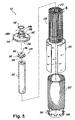
Fig. 2 is an exploded perspective view of an encapsulated filter cartridge constructed in accordance with an exemplary embodiment of the subject disclosure; -
Fig. 3 is an exploded perspective view of a filter assembly, with parts separated for ease of illustration; -
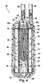
Fig. 4 is a cross-sectional view of an encapsulated filter cartridge with a filter assembly as shown inFig. 3 , wherein the direction of fluid flow through the encapsulated filter cartridge is illustrated by arrows; -
Fig. 5 is an exploded perspective view of an exemplary embodiment of a filter assembly according to the subject disclosure, with parts separated for ease of illustration; -
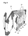
Fig. 6 is an enlarged sectional view of a pleated filter element that may be used in exemplary embodiments of the present disclosure, wherein the constituent layers are fanned out for illustration purposes; -
Fig. 7 is a cross-sectional view of an exemplary embodiment of an encapsulated filter cartridge according to the subject disclosure, with a filter assembly as shown inFig. 5 , wherein the direction of fluid flow through the encapsulated filter cartridge is illustrated by arrows; -
Fig. 7A is a relevant portion of a cross-sectional view of an exemplary embodiment of an encapsulated filter cartridge according to the subject disclosure, illustrating an alternative structure of an upper end cap; -
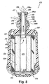
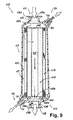
Fig. 8 is a cross-sectional view of another exemplary embodiment of an encapsulated filter cartridge according to the subject disclosure, with a filter assembly including a carbon block filter element and a pleated filter element, wherein the direction of fluid flow through the encapsulated filter cartridge is illustrated by arrows; and -
Fig. 9 is a cross-sectional view of yet another exemplary embodiment of an encapsulated filter cartridge according to the subject disclosure, with a filter assembly including a carbon block filter element and a pleated filter element, wherein the direction of fluid flow through the encapsulated filter cartridge is illustrated by arrows. - Referring now to the drawings, wherein like reference numerals identify similar structural elements of the filtration device described herein, there is illustrated in
Fig. 1A a disposable encapsulated filter cartridge constructed in accordance with an exemplary embodiment of the subject disclosure and designated generally byreference numeral 10. As illustrated inFigs. 2 ,4 and7 , the filter cartridge 10,110,210 includes a sump 12,112,212 having an interior chamber 20,120,220 for supporting a filter assembly 22,122,222 and a closure cap 14,114,214 at the bottom end thereof for permanently enclosing the filter cartridge within the sump. The closure cap 14,114,214 is preferably spun welded to the bottom end of the sump 12,112,212. Other ways in which the closure cap 14,114,214 may be joined to the bottom end of the sump 12,112,212 may include ultrasonic welding, hot plate welding, induction welding, overmolding and mechanical securement means. - The sump 12,112,212 has an inlet tube 16,116,216 for the ingress of fluid into the interior chamber 20,120,220 of the sump 12,112,212 and an outlet tube 18,118,218 for the egress of fluid from the interior chamber 20,120,220 at the top end of the sump 12,112,212. As illustrated in
Fig. 1B , theoutlet tube 18 may be generally aligned with the central axis of thesump 12 and theinlet tube 16 may be offset from the central axis of thesump 12. The inlet and outlet tubes 16,116,216 and 18,118,218 are preferably adapted and configured as quick connect/disconnect fittings for mating with corresponding reception ports (96,196,296 and 98,198,298) in an appliance. Preferably, the appliance is a water filtration appliance and, most preferably, it is a water filtration appliance in a refrigerator having an ice maker and/or a fluid dispenser. - Referring to
Figs. 3 ,4 ,5 , and7 , the filter assembly 122,222 includes a cylindrical carbon block filter element 124,224 having an axial cavity 126,226 that may or may not extend therethrough. Such a carbon block filter element may be produced, for example, according toU.S. Patent Nos. 5,928,588 and5,882,517 to Wei-Chih Chcn ct al., both assigned to Cuno Incorporated and incorporated herein by reference. The carbon block element 124,224 preferably has a k-value of between about 0.01 to about 0.10, and demonstrates superior adsorption capacity without any significant reduction in fluid flow rate, or a need for increased pressure to retain a desirable fluid flow rate. - As illustrated in
Figs. 3 and4 , thefilter assembly 122 may include aprefilter 125, made of any suitable material known to those of ordinary skill in the art, disposed around the outer circumference of thecarbon block element 124. Examples of prefilter materials include any suitable sheet-like fleeces of polypropylene, polyester, polyamide, resin-bonded or binder-free fibers (e.g., glass fibers), and other synthetics (woven and non-woven fleece structures); sintered materials such as polyolefins, metals, and ceramics; yams; special filter papers (e.g., mixtures of fibers, cellulose, polyolefins, and binders); polymer membranes; and others. Preferably, theprefilter 125 is made of a non-woven polypropylene (e.g., melt-blown) or a non-woven polyester. In addition toprefilter 125, thefilter assembly 122 may include aprotective netting 127 disposed around theprefilter 125 and securing theprefilter 125 around thecarbon block element 124. Theprotective netting 127 can be made of any suitable polymeric material or another material. For high temperature applications, a metallic mesh or screen may be used. - Referring further to
Figs. 3 and4 , thefilter assembly 122 includes a microporous filter element, which in this embodiment is ahollow fiber subassembly 130, housed within theaxial cavity 126 of thecarbon block element 124. As illustrated inFigs. 3 and4 and described in greater detail in the commonly assignedU.S. Patent No. 6,139,739 to Hamlin et al. , the disclosure of which is incorporated by reference herein, in appropriate embodiments of the subject disclosure, thehollow fiber subassembly 130 may include a bundle of hollow cylindrical fibers or thinmicroporous tubes 132, the opposed ends of which are preferably potted in a relativelynon-porous material 131 as known to those of ordinary skill in the art. In use, fluid is filtered while passing through the pores in the walls of the thin tubes orfibers 132. The fibers ortubes 132 are preferably made from a hydrophilic polysulfane and are potted at their ends with polyurethane, although nylon microporous tubes may also be used, as disclosed for example in commonly assignedU.S. Patent No. 5,151,180 to Giordano et al. , the disclosure of which is hereby incorporated by reference herein. Other suitable materials known to those of ordinary skill in the art also may be used to make or pot the hollow fibers ortubes 132, depending on the medium to be filtered and other relevant factors. - The
hollow fiber subassembly 130 may also include a perforated core tube orcage 134, surrounding thehollow fiber bundle 132. Preferably, the perforated core tube or cage is constructed so that at least about 40% of the fibers' surface area is exposed to the radial flow of the filtrate. More preferably, the fibers' surface area exposed to the radial flow of the filtrate is at least about 50%, and even more preferably, at least about 70%. Theaxial cavity 126 in thecarbon block element 124 may also contain aperforated liner tube 128 for providing additional support to thecarbon block element 124. Thehollow fiber bundle 132 surrounded by a perforated core tube orcage 134 may be supported within theliner tube 128 by anannular flange 136 formed below the top end of thecore tube 134. Theperforated liner tube 128 is also preferably constructed so that at least about 40% of the fibers' surface area is exposed to the radial flow of the filtrate. More preferably, the fibers' surface area exposed to the radial flow of the filtrate is at least about 50%, and even more preferably, at least about 70%. In some applications, the perforated core orcage 134 and theperforated liner tube 128 may consist of a material that has heat expansion coefficients comparable with those of the filter media. Preferably, both thecore tube 134 and theliner tube 128 have perforations or openings that are sufficiently large so as not to obstruct the flow of fluid and produce no significant pressure drop. - As illustrated in
Figs. 3 and4 , theupper portion 134a of thecore tube 134 extends beyond the top end of the carbonblock filter element 124, and anannular sealing ring 138 is positioned about theupper portion 134a of thecore tube 134 spaced from and above theannular flange 136. Theannular sealing ring 138 facilitates sealed engagement of theupper portion 134a of thecore tube 134 within anupper end cap 142. - Referring to
Figs. 2 ,3 and4 , the upper end cap 42,142 is operatively associated with the top end of the filter assembly 22,122. As illustrated inFigs. 2 ,3 and4 , the upper end cap 42,142 preferably is configured to receive the upper end of the carbon block element 24,124 and, in the appropriate embodiments, the upper end of thefiber subassembly 130. The upper end cap 42,142 may include a depending outer flange 44,144 having a plurality of circumferentially located and spaced apart flow channels 46,146 formed therein, which are best seen inFigs. 2 and3 . In addition, the upper end cap 42,142 may include a stepped neck portion 48,148 having aninterior bore 48a,148a for sealingly receiving theupper portion 34a,134a of the core tube 34,134. - The exterior of the neck portion 48,148 may carry an annular sealing ring 50,150 positioned thereabout and dimensioned and configured for sealed engagement within an annular reception collar 152 (shown in
Fig. 4 ), which may be located generally around the outlet tube 18,118 and project downwardly from the upper end of the interior chamber 20,120 of the sump 12,112. The sealed engagement of the neck portion 48,148 of the upper end cap 42,142 within thereception collar 152 of the sump 12,112 facilitates communication between thehollow fiber subassembly 130 of the filter assembly 22,122 and the central outlet tube 18,118 of sump 12,112. The exterior of the neck portion 48,148 may further include a stepped portion 48b,148b located below and spaced apart from the sealing ring 50,150 for further facilitation of the engagement of the neck portion 48,148 by thereception collar 152. - With continuing reference to
Figs. 2 ,3 and4 , a lower end cap 40,140 is operatively associated with the bottom end of filter assembly 22,122. Preferably, thelower end cap carbon block element 124 and may also be adapted and configured to support the filter assembly 22,122 within the sump 12,112. According to a preferred embodiment of the subject invention, the lower end cap 40,140 includes a plurality of circumferentially disposed outwardly flared fingers 60,160 for engaging the wall of the interior chamber 20,120 of the sump 12,112. - Referring specifically to
Fig. 4 , which has a set of arrows indicating the direction of the flow of filtrate through the encapsulatedfilter cartridge 110, in operation, unfiltered medium enters theupper region 120a of theinterior chamber 120 of thesump 112 through theinlet tube 116. The unfiltered medium then propagates through the circumferentially located and spaced apart channels 146 (seeFig. 3 ) formed in theouter flange 144 of theupper end cap 142, and further into the lower portions of theinterior chamber 120 of thesump 112. In the embodiments of the subject invention that include theprefilter 125, the unfiltered medium first passes through theprefilter 125 and then propagates radially inwardly through thecarbon block element 124. In the exemplary embodiments, the medium then passes through the perforations of theliner tube 128 and through the perforations of thecore tube 134 before entering thehollow fibers 132 of thehollow fiber subassembly 130. In the embodiments that do not include theliner tube 128 or thecore tube 134, the medium exiting thecarbon block element 124 then enters thehollow fibers 132 of thehollow fibers subassembly 130. After traversing thehollow fiber subassembly 130 in the upward direction, the filtered medium exits the interior chamber of thesump 120 offilter cartridge 110 through theoutlet tube 118. - The encapsulated
filter cartridge 110 constructed in accordance with the subject disclosure as described above has various advantages over the prior art. Among those advantages are the increased ease of manufacturing and superior performance characteristics due to the permanent encapsulation of thefilter assembly 122 within thesump 120 by theclosure cap 114. Thefilter cartridge 110 need not be opened in order to replace thefilter assembly 122, but is removed and discarded as a unit. This feature helps avoid contamination of the surrounding areas by stray particles from thefilter assembly 122, promotes air- or fluid-tight operation of thefilter cartridge 110, and facilitates contamination-free operation at thefilter assembly 122. - According to an exemplary embodiment of the present disclosure, illustrated in
Figs. 5 and7 , thefilter assembly 222 includes a microporous filter element, which in this embodiment is a generally cylindricalpleated filter element 270, disposed around the outer circumference of acarbon block element 224.Filter assemblies 222 suitable for use in the appropriate embodiments of the present disclosure are described in a U.S. Patent Application entitled "Filter Assembly Utilizing Carbon Block and Pleated Filter Element," Serial No. filed on even date herewith, the disclosure of which is hereby incorporated by reference herein. - The
pleated filter element 270 may include amembrane structure 272. Materials suitable for use as a part of themembrane structure 272 include a variety of polymeric materials having porous voids, such as cellulose acetate (CA), polysulfone (PSU), polyethersulfone (PESU), polyamide (PA), polyvinylidene fluoride (PVDF), polytetrafluoroethylene (PTFE), polycarbonate (PC), polypropylene (PP), and nylon. Average pore sizes of the materials included in themembrane structure 272 generally range between about 0.05 and about 5 microns, depending on the particular requirements of the application. The thickness of themembrane structure 272 generally range between about 130 and about 300 microns, while the thickness of thepleated element 270 may be much larger. It will be also understood by those of ordinary skill in the art that the subject disclosure encompasses the use of spiral-pleated membrane structures, radial pleated membrane structures, straight non-radial pleated membrane structures, membrane structures with pleats oriented orthogonally to the central axis, W-shaped multi-pleat structures (radial or spiral), modified W-shaped pleat structures and any number and/or combinations thereof. - The
membrane structure 272 includes a plurality of layers of the same or different media disposed atop one another to a desired thickness. Themembrane structure 272 include a plurality of layers having different filtering characteristics. Themembrane structure 272 has a gradient porosity construction. "Gradient porosity" means, in the context of the subject disclosure, that the average pore size in themembrane structure 272 varies as a function of depth into the membrane. For example, themembrane structure 272 may include discrete zones or layers having different average pore sizes. - The
membrane structure 272 having a gradient porosity construction is illustrated inFig. 6 , which represents a sectional view of thepleated filter element 270 with the constituent layers fanned out for illustration purposes. In this embodiment, themembrane structure 272 includes adjacent layers ofmedia downstream layer 373 has a smaller average pore size thanlayers middle layer 372 may have the same or smaller average pore size than theupstream layer 371. In a preferred embodiment of the subject disclosure, the layers ofmedia media 373 has an average pore size rated at about 0.2 micron. - As shown in
Fig. 6 , thepleated filter element 270 may also include adrainage layer 271 upstream of themembrane element 272, adrainage layer 273 downstream of themembrane element 272, or both. One or both of thelayers membrane structure 272 and may be of the same or different construction and composition. On the other hand, some new polymeric materials, such as PSU, PESU, PVDF, and PTFE, can be pleated as a single- or multiple-layer membrane structure 272 without reinforcement. Preferably, layers 271 and 273 are distinct layers that are separate from themembrane structure 272 and can be in the form of a mesh, a screen, or a relatively coarsely porous woven or non-woven sheet. More preferably, theupstream layer 271 includes flexible sheeting of spun bounded polypropylene fibers and thedownstream layer 273 includes plastic netting. Other suitable materials and structures known to those of ordinary skill in the art may also be used to manufacture themembrane structure 272 and the support layers 271 and 273, depending on the medium to be filtered, the temperature of the filtrate, and other relevant factors. - The
pleated filter element 270 may further include components other than themembrane structure 272 and the drainage layers 271, 273. For example, a cushioning layer 275 (or layers) may be placed between themembrane structure 272 and one or both of the drainage layers 271, 273. Such a cushioning layer or layers 275 may be included in thepleated filter element 270 in order to prevent abrasion of themembrane structure 272 due to its surface contact with the drainage layers 271 and 273, when the filter media expand and contract in response to pressure and/or temperature fluctuations of the fluid in the system in which the filter is installed. The cushioning layer or layers 275 are preferably made of a material smoother than the drainage layers 271,273 and having a higher resistance to abrasion than the media of themembrane structure 272. - The
filter assembly 222 according to the disclosed exemplary embodiment may also include aprefilter 225, made of any suitable material known to those of ordinary skill in the art, surrounding the outer circumference of thepleated filter element 270. Theprefilter 225 may be made of any material suitable for making theprefilter 125, described with reference toFigs. 3 and4 , or structures offering comparable or equivalent functionality. Preferably, theprefilter 225 is made of a non-woven polypropylene (e.g., melt-blown) or a non-woven polyester. In addition to theprefilter 225, thefilter assembly 222 may include aprotective netting 227 disposed around theprefilter 225 and securing theprefilter 225 about thepleated filter element 270. Theprotective netting 227 can be made of any suitable polymeric material or another material. For high temperature applications, a metallic mesh or screen may be used. - Referring to
Figs. 2 ,5 and7 , an upper end cap 42,242 may be operatively associated with the upper end of the filter assembly 22,222. As illustrated inFigs. 2 ,5 and7 , the upper end cap 42,242 preferably is configured to receive the upper end of thecarbon block element 224 and the upper end of thepleated filter element 270. The upper end cap 42,242 may include a depending outer flange 44,244 having a plurality of circumferentially located and spaced apart fluid flow channels 46,246 formed therein. In addition, the upper end cap may include a stepped neck portion 48,248. - The exterior of the neck portion 48,248 may carry an annular sealing ring 50,250 positioned thereabout and dimensioned and configured for sealed engagement within an annular reception collar 252 (shown in
Fig. 7 ), which may be located generally around the outlet tube 18,218 and project downwardly from the upper end of the interior chamber 20,220 of the sump 12,212. The sealed engagement of the neck portion 48,248 of the upper end cap 42,242 within thereception collar 252 of the sump 12,212 facilitates fluid communication between the axial cavity 20,220 in the carbon block element 24,224 and the central outlet tube 18,218 of the sump 12,212. The exterior of the neck portion 48,248 may further include a steppedportion 48b,248b located below and spaced apart from the sealing ring 50,250 for facilitation of sealing engagement of the neck portion 48,248 by thereception collar 252. In the embodiment of the present disclosure shown inFigs. 5 and7 , thefilter assembly 222 may also include anadapter 239 having anaxial bore 336 therethrough and operatively associated with the upper end of thecarbon block element 224 and with theupper end cap 242 to further facilitate fluid communication between theaxial cavity 226 in thecarbon block element 224 and theoutlet tube 218 of thesump 212. Preferably, theadapter 239 has a firstcylindrical portion 334, configured to fit within theaxial cavity 226 of thecarbon block element 224, aflange 332, and a secondcylindrical portion 330 configured to fit within theupper end cap 242. - An alternative to the
adapter 239 is illustrated inFig. 7A , which shows a relevant portion of a cross-section of an encapsulatedfilter cartridge 410 constructed in accordance with the present disclosure. The encapsulatedfilter cartridge 410 has asump 412 that includes areception collar 452 and is configured to accommodate afilter assembly 422 within theinterior chamber 420 of thesump 412. Thefilter assembly 422 includes a carbonblock filter element 424 and apleated filter element 470. Thefilter assembly 422 further includes anupper end cap 442 operatively associated with the upper end of thefilter assembly 422 and having aneck portion 448 and anadapter portion 439. In the exemplary embodiment illustrated inFig. 7A , theadapter portion 439 is an integral part of theupper end cap 442. - With continuing reference to
Figs. 2 ,5 and7 , in the appropriate embodiments of the subject disclosure, a lower end cap 40,240 is operatively associated with the bottom end of thefilter assembly 222. Preferably, in this embodiment of the present disclosure, thelower end cap carbon block element 224 and the lower end of thepleated element 270 and may also be adapted and configured to support thefilter assembly 222 within thesump 212. According to a preferred embodiment of the subject disclosure, the lower end cap 40,240 includes a plurality of circumferentially disposed outwardly flared fingers 60,260 for engaging the wall of the interior chamber 20,220 of the sump 12,212. - Referring specifically to
Fig. 7 , which has a set of arrows indicating the direction of the filtrate flow through the encapsulatedfilter cartridge 210, in operation, unfiltered medium enters theupper region 220a of theinterior chamber 220 of thesump 212 through theinlet tube 216. In the appropriate embodiments of the subject disclosure, the unfiltered medium then propagates through the circumferentially located and spaced apart flow channels 246 (seeFig. 5 ) formed in theouter flange 244 of theupper end cap 242, and further into the lower portions of theinterior chamber 220 of thesump 212. In the embodiments of the subject disclosure that include theprefilter 225, the unfiltered medium propagates first through the prefilter before entering thepleated filter element 270. Upon passing through the constituent components of thepleated filter element 270, the fluid propagates radially inwardly through thecarbon block element 224 and into theaxial cavity 226. After travelling through theaxial cavity 226 of thecarbon block element 224 in the upward direction, and, in the appropriate embodiments, through theaxial bore 336 of theadapter 239 or through theadapter portion 439 of the end cap 442 (seeFig. 7A ), the filtered medium exits the interior of thefilter cartridge 210 through theoutlet tube 218. - The encapsulated
filter cartridge 210 constructed in accordance with the subject disclosure as described above also has various advantages over the prior art. Among those advantages are the increased ease of manufacturing and superior performance characteristics due to the permanent encapsulation of thefilter assembly 222 within thesump 212 by theclosure cap 214. Thefilter cartridge 210 need not be opened in order to replace thefilter assembly 222, but is removed and discarded as a unit. This feature helps avoid contamination of the surrounding areas by stray particles from thefilter assembly 222, promotes air- or water-tight operation of thefilter cartridge 210, and facilitates contamination-free operation of thefilter assembly 222. - Among the advantages of the
filter assembly 222 having apleated element 270 disposed upstream of thecarbon block filter 224 element is its capability of retaining microorganisms before they can enter thecarbon block element 224 where they can potentially grow, multiply and eventually colonize the filter cartridge. In addition, because in this embodiment thecarbon block element 224 is located downstream of thepleated element 270, any undesirable odor or taste generated in thepleated element 270, e.g., due to the presence of microorganisms, may be subsequently removed by thecarbon block element 224. -
Fig. 8 shows a disposable encapsulated filter cartridge constructed in accordance with an alternative embodiment of the subject disclosure and designated generally byreference numeral 510. As illustrated inFig. 8 , thefilter cartridge 510 includes asump 512 having aninterior chamber 520 configured for supporting afilter assembly 522 and aclosure cap 514 at the bottom end thereof for permanently enclosing thefilter assembly 522 within theinterior chamber 520 of thesump 512. Theclosure cap 514 is preferably spun welded to the bottom end of thesump 512. Other ways in which theclosure cap 514 may be joined to the bottom end of thesump 512 may include ultrasonic welding, hot plate welding, induction welding, overmolding and mechanical securement means. - With continuing reference to
Fig. 8 , thesump 512 includes an elongatedtop portion 598 having apassage 588 extending therethrough and having aninlet 516 for the ingress of filtrate into theinterior chamber 520 of thesump 512 and anoutlet 518 for the egress of filtrate from theinterior chamber 520 at the top end of thesump 512. Theinlet 516 may be an opening in the radially outer surface of the elongatedtop portion 598, as illustrated inFig. 8 , that communicates with thepassage 588. Thepassage 588 may include separate fluid flow channels in order to facilitate communication between theinlet 516 and theinterior chamber 520 of thesump 512. - The
outlet 518 is located at the top of the elongatedtop portion 598 and is generally aligned with the central axis of thesump 512. Theinlet 516 andoutlet 518 are preferably adapted and configured for mating with an appropriate port or module of an appliance, such as a water filtration appliance. Alternatively, theinlet 516 andoutlet 518 may be adapted and configured for mating with an adapter, which, in turn, may be configured for mating with an appliance. - The elongated
top portion 598 of thesump 512 may have stepped portions 598a and 598b and may also bear asealing ring 517 disposed around the stepped portion 598a located above theinlet 516 and asealing ring 515 disposed around the stepped portion 598b located below theinlet 516 to facilitate sealing engagement of the elongatedtop portion 598 with the appropriate portions of the appliance for which it is configured, or with the appropriate portions at an adapter, as will be understood by those of ordinary skill in the art. - Similar to exemplary embodiments of the subject disclosure shown in
Figs. 5 and7 , thefilter assembly 522 of the encapsulatedfilter cartridge 510 includes a microporous filter element, which in this embodiment is a generally cylindricalpleated filter element 570, disposed around the outer circumference of acarbon block element 524. Both the carbonblock filter element 524 and thepleated filter element 570 of this exemplary embodiment are substantially as described in detail above in reference to other embodiments of the subject disclosure. In addition, thefilter assembly 522 may include any number and/or combination of elements described above in reference to other exemplary embodiments. - With continuing reference to
Fig. 8 , anupper end cap 542 is operatively associated with the upper end of thefilter assembly 522. Preferably, theupper end cap 542 is configured to receive the upper end of thecarbon block element 524 and the upper end of thepleated filter element 570. Theupper end cap 542 may include a dependingouter flange 544 having a plurality of circumferentially located and spaced apart fluid flow channels (seeelements Figs. 2 ,3 and5 ) formed therein. In addition, theupper end cap 542 may include a steppedneck portion 548 having a stepped portion 548b and anaxial passage 548a extending therethrough. The steppedneck portion 548 is configured to be accommodated within thepassage 588 of the elongatedtop portion 598 of thesump 512 and to allow the unfiltered medium entering theinlet 516 to pass into the lower regions of theinterior chamber 520 of thesump 512 for communication with the radially outer surface of the filter assembly 552. The exterior of theneck portion 548 may carry anannular sealing ring 550 positioned thereabout above the stepped portion 548b and dimensioned and configured for sealed engagement within thepassage 588 of in the elongatedtop portion 598 of thesump 512. - In the appropriate embodiments of the subject disclosure, a
lower end cap 540 is operatively associated with the lower end of thefilter assembly 522. Preferably, in this embodiment of the present disclosure, thelower end cap 540 is configured to receive the lower end of thecarbon block element 524 and the lower end of thepleated element 570 and may also be adapted and configured to support thefilter assembly 522 within thesump 512. Preferably, thelower end cap 540 has a structure similar to the lower and caps of exemplary embodiments shown inFigs. 2 ,3 and5 and described in detail above. - Referring further to
Fig. 8 , which has a set of arrows indicating the direction of the filtrate flow through the encapsulatedfilter cartridge 510, in operation, unfiltered medium enters through theinlet 516 in the elongatedtop portion 598 of thesump 512 into the region between the interior surface of thepassage 588 and the outer surface of the steppedneck portion 548. In the appropriate embodiments of the subject disclosure, the unfiltered medium then propagates through the circumferentially located and spaced apart flow channels formed in theouter flange 544 of theupper end cap 542, and further into the lower portions of theinterior chamber 520 of thesump 512. - The unfiltered medium then enters the radially outer surface of the
filter assembly 522 and propagates radially inwardly into theaxial cavity 526 of the carbonblock filter element 524. After travelling along theaxial cavity 526 of thecarbon block element 524 in the upward direction, and, in the appropriate embodiments, through theaxial passage 548a of theend cap 542, the filtered medium exits the interior of thefilter cartridge 510 through theoutlet 518. -
Fig. 9 shows a disposable encapsulated filter cartridge constructed in accordance with another alternative embodiment of the subject disclosure and designated generally byreference numeral 610. As illustrated inFig. 9 , thefilter cartridge 610 includes asump 612 having aninterior chamber 620 configured for supporting afilter assembly 622 and aclosure cap 614 at the bottom end thereof for permanently enclosing thefilter assembly 622 within thesump 612. Theclosure cap 614 is preferably spun welded to the bottom end of thesump 612. Other ways in which theclosure cap 614 may be joined to the bottom end of thesump 612 may include ultrasonic welding, hot plate welding, induction welding and overmolding. - With continuing reference to
Fig. 9 , thesump 612 includes an elongatedtop portion 696 having anannular flange 696b andaxial passage 696a extending therethrough and having aninlet 616 for the ingress of filtrate into theinterior chamber 620 of thesump 612. According to this exemplary embodiment, theclosure cap 614 includes anelongated portion 698 having an annular flange 698b and anaxial passage 698a extending therethrough. Anoutlet 618 for the egress of filtered media from theinterior chamber 620 may be located at the bottom end of theelongated portion 698 of theclosure cap 614. Theinlet 616 and theoutlet 618 are generally aligned with the central axis of thesump 612. Theinlet 616 is in communication with the radially outer surface of thefilter assembly 622, while theoutlet 618 is in communication with theaxial cavity 626 of thecarbon block element 624. The inlet andoutlet - Similarly to previously described embodiments, the
filter assembly 622 of the encapsulatedfilter cartridge 610 includes a microporous filter element, which in this embodiment is a generally cylindricalpleated filter element 670, disposed around the outer circumference of acarbon block element 624. Both the carbonblock filter element 624 and thepleated filter element 670 of this exemplary embodiment are substantially as described in detail above in reference to other embodiments of the subject disclosure. In addition, thefilter assembly 622 may include any number and/or combination of elements described above in reference to other exemplary embodiments. - With continuing reference to
Fig. 9 , anupper end cap 642 is operatively associated with the upper end of thefilter assembly 622. Preferably, theupper end cap 642 is configured to receive and scalingly enclose the upper end of thecarbon block element 624 and the upper end of thepleated filter element 670, so as to prevent filtrate from entering through the top surface of the filter assembly. - In the appropriate embodiments of the subject disclosure, a
lower end cap 640 is operatively associated with the bottom end of thefilter assembly 622. Thelower end cap 640 has an axial passage 640a therethrough and a generally cylindrical portion 640a and preferably is configured to be secured to theclosure cap 614. Thelower end cap 640 preferably is configured to receive the lower end of thecarbon block element 624 and the lower end of thepleated element 670 and sealingly secured to theclosure cap 614 to prevent the unfiltered medium from entering the stream of filtered medium passing through the axial passage 640a to theoutlet 618. The ways of sealingly securing the cylindrical portion 640a to theclosure cap 614 may include the use of an O-ring, welding and other structures and methods known to those of ordinary skill in the art. - Optionally, the
sump 612 may include avent 720 for venting air from theinterior chamber 620 of thesump 612 upon the start-up of the filtering process. Thevent 720 includes avent cap 714 for selective opening of thevent 720 and asealing ring 712 for sealing engagement of thevent cap 714. It will be understood by those of ordinary skill in the art that any structure may be used in place of thevent 720 that will perform a similar function. - Further, the
sump 612 may optionally include adrain 710 for draining theinterior chamber 620 of thesump 612 of the remaining filtrate prior to disposal of the filter cartridge. Thedrain 710 includes adrain cap 714 for selective opening of thedrain 710 and asealing ring 712 for sealing engagement of thedrain cap 714. It will be understood by those of ordinary skill in the art that any structure may be used in place of thedrain 710 that will perform a similar function. - Referring further to
Fig. 9 , which has a set of arrows indicating the direction of the filtrate flow through the encapsulatedfilter cartridge 610, in operation, unfiltered medium enters through theaxial passage 696a into theupper region 620a of theinterior chamber 620 of thesump 612. The unfiltered medium then enters the radially outer surface of thefilter assembly 622 and propagates radially inwardly into theaxial cavity 626 of the carbonblock filter element 624. After travelling along theaxial cavity 626 of thecarbon block element 624 in the downward direction, through the axial passage 640a of theend cap 640, and then through theaxial passage 698a, the filtered medium exits theinterior chamber 620 of thefilter cartridge 610 through theoutlet 618. - The encapsulated filter cartridges 510,610 constructed in accordance with the subject disclosure as described above also have various advantages over the prior art. Among those advantages are the increased ease of manufacturing and superior performance characteristics due to the permanent encapsulation of the filter assembly 522,622 within the sump 512,612 by the closure cap 514,614. The filter cartridge 510,610 need not be opened in order to replace the filter assembly 522,622 but is removed and discarded as a unit. This feature helps avoid contamination of the surrounding areas by stray particles from the filter assembly 522,622 promotes air- or fluid-tight operation of the filter cartridge 510,610 and facilitates contamination-free operation of the filter assembly 522,622.
- In addition, among the advantages of the filter assembly 522,622 having a pleated element 570,670 disposed upstream of the carbon block filter 524,624 element is its capability of retaining microorganisms before they can enter the carbon block element 524,624 where they can grow, multiply and eventually colonize the filter cartridge. In addition, because in this embodiment the carbon block element 524,624 is located downstream of the pleated element 570,670 any undesirable odor or taste generated in the pleated element 570,670, e.g., due to the presence of microorganisms, may be subsequently removed by the carbon block element 524,674.
- Although the encapsulated filter cartridge assemblies constructed in accordance with the subject disclosure have been described with respect to specific embodiments, those skilled in the art will readily appreciate that changes and modifications may be made thereto without departing from the spirit and scope of the present invention. For example, the encapsulated filter cartridges constructed in accordance with the subject disclosure may be used for pressurized as well as for gravity-fed applications.
Claims (19)
- An encapsulated filter cartridge (210), comprising:a) a filter assembly (222) having an upper end (242), a lower end (240) and a radially outer surface, said filter assembly including:(i) a carbon block filter element (224) having a radially outer surface and an axial cavity;(ii) a pleated filter element (270) surrounding the radially outer surface of the carbon block element; andb) a permanently sealed sump (212) defining an interior chamber (220) configured to accommodate the filter assembly (220), the sump having an inlet (216) for permitting unfiltered fluid to enter the interior chamber fcr communicating with the radially outer surface of the filter assembly, and an outlet (218) for permitting filtered fluid to exit the interior chamber from the axial cavity of the carbon block element,wherein the pleated filter element includes a microporous membrane structure (272) having a gradient porosity construction which has discrete zones of different average pore size, the filter element being positioned upstream of the carbon block filter element.
- The encapsulated filter cartridge of claim 1, wherein the filter assembly further comprises an upper end cap (242) operatively associated with the upper end of the filter assembly (222).
- The encapsulated filter cartridge of claim 2, wherein said upper end cap (242) has a neck portion (248) and an axial fluid passage (48a, 148a) extending therethrough for fluid communication between the axial portion of the filter assembly and the outlet (218) of the sump (212).
- The encapsulated filter cartridge of claim 3, further comprising a sealing ring (250) disposed around the neck portion (248) of the upper and cap (242).
- The encapsulated filter cartridge of claim 4, further comprising a reception collar (252) surrounding the outlet (218) of the sump (212) for sealing engagement of the neck portion (248) of the upper end cap (242).
- The encapsulated filter cartridge of claim 2, wherein said upper end cap (242) is configured to receive and sealingly enclose the upper end of the filter assembly (222).
- The encapsulated filter cartridge of claim 1, wherein the filter assembly further comprises a lower end cap (240) operatively associated with the lower end of the filter assembly (222).
- The encapsulated filter cartridge of claim 7, wherein the lower end cap (242) is adapted for supporting the filter assembly (222) within the interior chamber of the sump (212).
- The encapsulated filter cartridge of claim 8, wherein the lower end cap (242) comprises a plurality of fingers (260) for engaging a wall of the interior chamber of the sump.
- The encapsulated filter cartridge of claim 7, wherein the lower end cap (242) includes an axial passage extending therethrough for communication between the axial portion of the filter assembly and the outlet of the sump.
- The encapsulated filter cartridge of claim 1, wherein the sump (212) includes a closure cap (214) permanently sealing the sump at one end.
- The encapsulated filter cartridge of claim 11, wherein the closure cap (214) is joined to the end of the sump (212) by spun welding, ultrasonic welding, hot plate welding, induction welding or overmolding.
- The encapsulated filter cartridge of claim 11, wherein the closure cap has an axial passage (218) therethrough for communication between the axial portion (226) of the filter assembly (222) and the outlet of the sump (218).
- The encapsulated filter cartridge of claim 1, further comprising an inlet tube (216) operatively associated with the inlet of the sump (212) and an outlet tube (218) operatively associated with the outlet of the sump, said inlet and outlet tubes both configured as fittings for mating with an appliance.
- The encapsulated filter cartridge of claim 1, further comprising means (720) for venting air from the interior chamber (220, 620) of the sump (212, 612).
- The encapsulated filter cartridge of claim 1, further comprising means (710) for draining filtrate from the interior chamber (220, 620) of the sump (212, 612).
- The encapsulated filter cartridge of claim 1 wherein a downstream discrete zone (373) has a smaller average pore size than at least one upstream discrete zone (371, 372).
- The encapsulated filter cartridge of claim 17 wherein a downstream discrete zone (373) has an average pore size rated at about 0.2 micron and an upstream discrete zone (371, 372) has an average pore size rated at about 0.65 micron.
- The encapsulated filter cartridge of claim 17 wherein downstream adjacent membrane structure discrete zones (373) have a smaller average pore size than at least one upstream discrete zone (371, 372).
Applications Claiming Priority (3)
| Application Number | Priority Date | Filing Date | Title |
|---|---|---|---|
| US37406702P | 2002-04-19 | 2002-04-19 | |
| US374067P | 2002-04-19 | ||
| PCT/US2003/012161 WO2003089104A2 (en) | 2002-04-19 | 2003-04-18 | Encapsulated filter cartridge |
Publications (2)
| Publication Number | Publication Date |
|---|---|
| EP1536875A2 EP1536875A2 (en) | 2005-06-08 |
| EP1536875B1 true EP1536875B1 (en) | 2011-11-23 |
Family
ID=29251129
Family Applications (1)
| Application Number | Title | Priority Date | Filing Date |
|---|---|---|---|
| EP03724122A Expired - Lifetime EP1536875B1 (en) | 2002-04-19 | 2003-04-18 | Encapsulated filter cartridge |
Country Status (7)
| Country | Link |
|---|---|
| US (2) | US7081201B2 (en) |
| EP (1) | EP1536875B1 (en) |
| JP (1) | JP2005523144A (en) |
| CN (1) | CN100421760C (en) |
| AU (1) | AU2003231002B2 (en) |
| BR (1) | BR0308964B1 (en) |
| WO (1) | WO2003089104A2 (en) |
Families Citing this family (124)
| Publication number | Priority date | Publication date | Assignee | Title |
|---|---|---|---|---|
| US8241494B2 (en) * | 2001-03-20 | 2012-08-14 | Assion Norbert M | Liquid filter assembly |
| US20040206682A1 (en) * | 2003-04-18 | 2004-10-21 | Thomas Hamlin | Filter assembly utilizing carbon block and pleated filter element |
| CN100402123C (en) * | 2003-05-01 | 2008-07-16 | 安格斯公司 | Filter unit with deaerating mechanism |
| US7673756B2 (en) * | 2005-06-29 | 2010-03-09 | Selecto, Inc. | Modular fluid purification system and components thereof |
| US8277654B2 (en) * | 2003-11-26 | 2012-10-02 | Selecto, Inc. | Water purification apparatus and system |
| US20050133431A1 (en) * | 2003-12-23 | 2005-06-23 | Schulz Christopher R. | In-home water treatment system |
| EP1799323B1 (en) * | 2004-08-05 | 2012-01-25 | Parker Hannifin Limited | Filter assembly |
| US20060043027A1 (en) * | 2004-09-01 | 2006-03-02 | Nguyen Ledu Q | Automotive fluid filter with sintered pellet filter medium and associated method |
| WO2006039538A2 (en) * | 2004-09-29 | 2006-04-13 | 3M Innovative Properties Company | Counter top water filtration system |
| EP1807171A1 (en) * | 2004-10-15 | 2007-07-18 | Cuno Incorporated | Pleated multi-layer filter media and cartridge |
| US20060151376A1 (en) * | 2004-12-23 | 2006-07-13 | Tubbs R W | Water filter apparatus |
| JP2008531249A (en) * | 2005-02-22 | 2008-08-14 | ボールドウィン フィルターズ,インコーポレイティド | Filter device |
| US8057669B2 (en) | 2005-02-22 | 2011-11-15 | Baldwin Filters, Inc. | Filter element and filter assembly including locking mechanism |
| JP4715247B2 (en) * | 2005-03-10 | 2011-07-06 | 富士ゼロックス株式会社 | Filter device and droplet discharge device |
| EP1888200A1 (en) * | 2005-05-08 | 2008-02-20 | 3M Innovative Properties Company | Filter cartridge and method of construction thereof |
| FR2886690B1 (en) * | 2005-06-01 | 2011-05-06 | Air Liquide | FLUID TREATMENT FACILITY AND USE OF SUCH A PLANT FOR ADSORPTION GAS TREATMENT |
| US20070084782A1 (en) * | 2005-10-05 | 2007-04-19 | Enercon Services, Inc. | Filter medium for strainers used in nuclear reactor emergency core cooling systems |
| US8054932B2 (en) * | 2005-10-05 | 2011-11-08 | Enercon Services, Inc. | Filter medium for strainers used in nuclear reactor emergency core cooling systems |
| DE102005057137A1 (en) * | 2005-11-30 | 2007-06-06 | BSH Bosch und Siemens Hausgeräte GmbH | Refrigerating appliance and water filter for it |
| FR2896793B1 (en) * | 2006-01-27 | 2008-08-08 | Millipore Corp | SYSTEM AND METHOD FOR PURIFYING WATER |
| FR2896792B1 (en) * | 2006-01-27 | 2008-07-18 | Millipore Corp | SYSTEM AND METHOD FOR PURIFYING WATER |
| US20070251876A1 (en) * | 2006-04-28 | 2007-11-01 | Krogue John A | Hybrid filter element and method |
| US20080023405A1 (en) * | 2006-07-28 | 2008-01-31 | General Electric Company | Water filtration systems and methods |
| US20080023402A1 (en) * | 2006-07-28 | 2008-01-31 | General Electric Company | Water filtration systems and methods |
| US20080023403A1 (en) * | 2006-07-28 | 2008-01-31 | Rawson James R Y | Methods for removing insoluble lead from water |
| US7992723B2 (en) * | 2006-10-26 | 2011-08-09 | Pti Technologies, Inc. | Filter cartridge with inlet flow diffuser |
| WO2008096397A1 (en) * | 2007-02-02 | 2008-08-14 | Mitsui Engineering & Shipbuilding Co., Ltd. | Membrane treatment apparatus |
| KR100792479B1 (en) * | 2007-05-15 | 2008-01-10 | 주식회사 마이크로필터 | High turbid water filter apparatus with multi layer |
| US20100194007A1 (en) * | 2007-09-26 | 2010-08-05 | Craig Donald B | Novel filtration system for large cast iron castings |
| US20090092709A1 (en) * | 2007-10-03 | 2009-04-09 | Joint Juice, Inc. | Clear filtered nutritional supplement beverage and filtration method |
| CL2008002533A1 (en) * | 2007-10-20 | 2009-10-09 | Porous Media Corp | A filter assembly comprising a hollow casing open at least at one end at least one closure member that closes the at least one end, the removable closure member being, at least one tubular plate, one or plus holes or openings, an inlet bimpellent chamber formed in the hollow housing |
| US20090188856A1 (en) * | 2007-10-20 | 2009-07-30 | Robb Benson | Externally Centering Filter Element or Cartridge and Housing and System Utilizing the Same |
| JP2009136737A (en) * | 2007-12-05 | 2009-06-25 | Eco Work Co Ltd | Water treatment contact filter and water treatment apparatus |
| US8926840B2 (en) | 2008-03-18 | 2015-01-06 | Rubbermaid Incorporated | Drinking container and filter assembly |
| US20090255880A1 (en) * | 2008-04-14 | 2009-10-15 | Pritchard Scott J | Single use sanitary filter assembly |
| EP2113294A1 (en) | 2008-04-30 | 2009-11-04 | Filtrox AG | Filter module, filter device and use of a filter module |
| US8241493B2 (en) | 2008-06-16 | 2012-08-14 | Baldwin Filters, Inc. | Filter with ejection mechanism |
| US8815090B2 (en) * | 2008-06-16 | 2014-08-26 | Baldwin Filters, Inc. | Filter with water separation device |
| US8128819B2 (en) * | 2008-06-16 | 2012-03-06 | Baldwin Filters Inc. | Fluid filter, fluid filter assembly, and mounting method |
| US8501001B2 (en) * | 2008-11-05 | 2013-08-06 | Cummins Filtration Ip, Inc. | Fluid filter with an attachment structure on an endplate of the filtering element |
| US8146751B2 (en) * | 2008-11-25 | 2012-04-03 | Cummins Filtration Ip, Inc. | Filter element with threaded top endplate |
| CA2747907C (en) | 2008-12-22 | 2017-12-12 | 3M Innovative Properties Company | Refillable filter system |
| US20100155321A1 (en) * | 2008-12-23 | 2010-06-24 | Sasur Timothy M | Filter assembly |
| US20120241389A1 (en) * | 2009-10-30 | 2012-09-27 | Rubbermaid Commercial Products, Llc | Mop bucket filter |
| DE202009019064U1 (en) | 2009-12-18 | 2016-03-01 | Lifestraw Sa | Drinking straw with hollow fiber liquid filter |
| AP2012006363A0 (en) * | 2009-12-18 | 2012-08-31 | Vestergaard Frandsen Sa | Drinking straw with hollow fibre liquid filter |
| DE102010003980A1 (en) * | 2010-01-01 | 2011-07-07 | INFILTEC GmbH, 67346 | Filter for water treatment |
| DE102010009268A1 (en) * | 2010-02-25 | 2011-08-25 | MAHLE International GmbH, 70376 | Filter element and filter device |
| DE102010010964B4 (en) * | 2010-03-10 | 2022-12-22 | Mann+Hummel Gmbh | Filter element for fluid filtration and air filter unit, in particular for intake air of internal combustion engines. |
| US8707759B2 (en) * | 2010-03-17 | 2014-04-29 | Carrier Corporation | Flue gas sensor with water barrier member |
| US8544657B2 (en) | 2010-04-22 | 2013-10-01 | Kaydon Custom Filtration Corporation | Apparatus and method for removing contaminants from industrial fluids |
| US8701895B2 (en) * | 2010-05-11 | 2014-04-22 | Selecto, Inc. | Fluid purification media and systems and methods of using same |
| US8678201B2 (en) * | 2010-06-04 | 2014-03-25 | Goodrich Corporation | Aircraft potable water system |
| US9682335B2 (en) | 2011-02-24 | 2017-06-20 | Saint-Gobain Performance Plastics Corporation | Modular filter capsule apparatus |
| DE102011005932B4 (en) * | 2011-03-23 | 2022-07-14 | Robert Bosch Gmbh | Fluidic system for bubble-free filling of a microfluidic filter chamber and method for bubble-free filling and method for filtering a liquid with such a system |
| US10287179B2 (en) | 2012-01-09 | 2019-05-14 | General Ecology, Inc. | Drinking water filtration and/or purification apparatus |
| US20130220918A1 (en) * | 2012-02-24 | 2013-08-29 | Insonic Company | Double-layer filter strcutre |
| CN104144885B (en) * | 2012-02-29 | 2016-11-16 | 三菱丽阳株式会社 | Endoscope cleaning device defecator |
| US8991619B2 (en) | 2012-03-26 | 2015-03-31 | Baldwin Filters, Inc. | Filter assembly with water evacuation and methods |
| US9409108B2 (en) * | 2012-04-06 | 2016-08-09 | Saint-Gobain Performance Pastics Corporation | Modular filter capsule apparatus |
| US9320993B2 (en) | 2012-11-12 | 2016-04-26 | Whirlpool Corporation | Filter housing for small media |
| US9889478B2 (en) | 2012-11-12 | 2018-02-13 | Whirlpool Corporation | Consumable descaling cartridges for a refrigerator appliance |
| US9327216B2 (en) | 2012-11-12 | 2016-05-03 | Whirlpool Corporation | Customizable multi-stage water treatment system |
| US9314716B2 (en) | 2012-11-12 | 2016-04-19 | Whirlpool Corporation | Customizable multi-stage water treatment assembly |
| JP6339101B2 (en) | 2013-01-04 | 2018-06-06 | ボールドウィン・フィルターズ・インコーポレーテッドBaldwin Filters Inc | Filter element including three-part end cap and similar elements |
| US9474429B2 (en) | 2013-03-15 | 2016-10-25 | Rubbermaid Commercial Products, Llc | Clean water mopping system |
| US10240358B2 (en) | 2013-03-18 | 2019-03-26 | R&R Regester Enterprises, Inc. | Water treatment and purification system and methods thereof |
| JPWO2014196567A1 (en) * | 2013-06-06 | 2017-02-23 | 東レ株式会社 | Water purifier cartridge and water purifier |
| US9849407B2 (en) | 2013-07-12 | 2017-12-26 | Kx Technologies Llc | Carafe filter with air lock prevention feature |
| RU2540637C1 (en) * | 2013-10-07 | 2015-02-10 | Закрытое Акционерное Общество "Аквафор Продакшн" (Зао "Аквафор Продакшн") | Fabrication of porous composite filter element and filter element |
| AU2014366926B2 (en) * | 2013-12-18 | 2019-07-11 | Brita Lp | Filter media for filter as you pour filtration |
| US10654725B2 (en) | 2013-12-18 | 2020-05-19 | Brita Lp | Filter assembly for filter as you pour filtration |
| TWI621504B (en) * | 2014-05-19 | 2018-04-21 | 密科博股份有限公司 | Method for pre-wetting slurry pp filter |
| KR102263140B1 (en) | 2014-07-23 | 2021-06-10 | 엘지전자 주식회사 | Filter system |
| EP3233235B1 (en) * | 2014-12-16 | 2021-01-27 | Saint-gobain Performance Plastics Corporation | Modular filter capsule apparatus |
| EP3257822B1 (en) | 2015-02-09 | 2021-01-27 | Foshan Shunde Midea Water Dispenser MFG. Co., Ltd. | Water purifying system having an integrated composite filter cartridge |
| WO2016139654A1 (en) * | 2015-03-04 | 2016-09-09 | Advanced Mem-Tech Ltd. | Filtration membrane cartridge |
| US20180283759A1 (en) * | 2015-04-17 | 2018-10-04 | David Bess | Ice Tray Assembly |
| CN104941308A (en) * | 2015-06-03 | 2015-09-30 | 苏州凯虹高分子科技有限公司 | Three-in-one filter element |
| CN107847845B (en) * | 2015-06-08 | 2020-07-14 | 美国圣戈班性能塑料公司 | High pressure resistant filter |
| USD783773S1 (en) | 2015-07-14 | 2017-04-11 | Lifestraw Sa | Water purifier |
| USD782609S1 (en) | 2015-07-14 | 2017-03-28 | Lifestraw Sa | Water purifier |
| WO2017034813A1 (en) * | 2015-08-21 | 2017-03-02 | Cummins Filtration Ip, Inc. | Variable efficiency filtration media |
| JP6778047B2 (en) * | 2015-09-28 | 2020-10-28 | 株式会社キッツエスシーティー | High-pressure filter and hydrogen station using it |
| AU2016332961A1 (en) | 2015-09-30 | 2018-04-05 | Brita Lp | Filter cartridge placement in filter as you pour system |
| USD782610S1 (en) | 2015-11-09 | 2017-03-28 | Lifestraw Sa | Water purifier |
| RU2617779C1 (en) * | 2015-12-10 | 2017-04-26 | Закрытое Акционерное Общество "Аквафор Продакшн" (Зао "Аквафор Продакшн") | Device for purifying liquid |
| CN105649781B (en) * | 2016-01-20 | 2017-06-23 | 四川村田机械制造股份有限公司 | Based on the filter mechanism for improving gas effciency |
| DE102016107483A1 (en) * | 2016-04-22 | 2017-10-26 | Poromembrane Gmbh | Water treatment device |
| BR112018071685A2 (en) * | 2016-04-22 | 2019-02-19 | Pure Dragon Environmental Ltd. | device and method for removing pollutants from gas streams |
| DE102016107485A1 (en) * | 2016-04-22 | 2017-10-26 | Poromembrane Gmbh | Water treatment device |
| KR102090669B1 (en) * | 2016-05-02 | 2020-03-18 | 엘지전자 주식회사 | Filter system |
| KR102090659B1 (en) * | 2016-05-02 | 2020-04-14 | 엘지전자 주식회사 | Complex filter and filter system comprising the same |
| KR102090664B1 (en) * | 2016-05-02 | 2020-04-14 | 엘지전자 주식회사 | Filter system |
| KR102090654B1 (en) * | 2016-05-02 | 2020-03-18 | 엘지전자 주식회사 | Filter system |
| US10675569B1 (en) * | 2016-09-23 | 2020-06-09 | Fred Geyer | Portable water filter |
| EP3519075A4 (en) | 2016-10-03 | 2020-05-27 | Parker-Hannifin Corporation | Filter element with torsion lock and assembly |
| RU171023U1 (en) * | 2017-01-27 | 2017-05-17 | Федеральное государственное бюджетное образовательное учреждение высшего образования "Волгоградский государственный технический университет" (ВолгГТУ) | Cartridge |
| RU171495U1 (en) * | 2017-01-27 | 2017-06-02 | Федеральное государственное бюджетное образовательное учреждение высшего образования "Волгоградский государственный технический университет" (ВолгГТУ) | Cartridge |
| US20200038809A1 (en) * | 2017-03-07 | 2020-02-06 | Foshan Shunde Midea Water Dispenser Mfc. Co,, Ltd. | Composite filter cartridge, composite filter cartridge assembly and water purification system |
| US11571642B2 (en) * | 2017-05-11 | 2023-02-07 | Jeffrey Sandahi | Self cleaning water filter unit |
| RU173754U1 (en) * | 2017-05-24 | 2017-09-11 | Федеральное государственное бюджетное образовательное учреждение высшего образования "Вятская государственная сельскохозяйственная академия" (ФГБОУ ВО Вятская ГСХА) | FILTER CYLINDER |
| WO2018222804A2 (en) | 2017-05-31 | 2018-12-06 | Parker-Hannifin Corporation | Filter element with torsion lock and/or sliding piston, assembly and methods |
| RU175288U1 (en) * | 2017-06-05 | 2017-11-29 | Федеральное государственное бюджетное образовательное учреждение высшего образования "Вятская государственная сельскохозяйственная академия" (ФГБОУ ВО Вятская ГСХА) | FILTER PERFORATED WITH DOUBLE DOWNLOAD |
| US10793457B2 (en) * | 2017-08-02 | 2020-10-06 | James Atlas Kalp | Pedicure, manicure, and massage spa water treatment system |
| CN111727484B (en) * | 2017-10-06 | 2023-10-10 | 坎杜能源公司 | Method and device for filtering fluid in nuclear power generation |
| US11090588B2 (en) * | 2017-12-21 | 2021-08-17 | Pepsico, Inc. | Water filtration system |
| CN110404328B (en) * | 2018-04-27 | 2024-02-20 | 芜湖美的厨卫电器制造有限公司 | Composite filter element and water purifying equipment |
| US11110397B2 (en) * | 2018-06-04 | 2021-09-07 | Pure Berkey, Llc | Device and method for water priming microporous-carbon water filters using negative pressure |
| RU186242U1 (en) * | 2018-09-03 | 2019-01-14 | Федеральное государственное бюджетное образовательное учреждение высшего образования "Волгоградский государственный технический университет" (ВолгГТУ) | Cartridge for cleaning liquids |
| RU186309U1 (en) * | 2018-09-03 | 2019-01-15 | Федеральное государственное бюджетное образовательное учреждение высшего образования "Волгоградский государственный технический университет" (ВолгГТУ) | Cartridge for cleaning liquids |
| RU186249U1 (en) * | 2018-09-03 | 2019-01-14 | Федеральное государственное бюджетное образовательное учреждение высшего образования "Волгоградский государственный технический университет" (ВолгГТУ) | Cartridge for cleaning liquids |
| RU186252U1 (en) * | 2018-09-03 | 2019-01-14 | Федеральное государственное бюджетное образовательное учреждение высшего образования "Волгоградский государственный технический университет" (ВолгГТУ) | Cartridge for cleaning liquids |
| DE102018121904A1 (en) * | 2018-09-07 | 2020-03-12 | Instraction Gmbh | Double hollow jacket cartridge with central drain |
| RU187521U1 (en) * | 2018-10-05 | 2019-03-11 | Виктор Ефимович Саитов | FILTER PERFORATED |
| TW202031958A (en) | 2018-12-05 | 2020-09-01 | 奧地利商蘭仁股份有限公司 | Method and device for producing tubular cellulosic spunbonded nonwoven fabrics |
| KR102212152B1 (en) * | 2019-03-05 | 2021-02-04 | 한국과학기술연구원 | Filter apparatus for oil-water separation |
| US10994229B1 (en) | 2019-11-15 | 2021-05-04 | Ip33 Ltd | Water filtration system |
| US11376529B2 (en) | 2019-11-15 | 2022-07-05 | Ip 33 Ltd | Particle filter system |
| US11780740B2 (en) | 2020-02-25 | 2023-10-10 | Nils Nedrelid | System of filtering runoff water from a roof cleaning |
| US20220105455A1 (en) * | 2020-10-02 | 2022-04-07 | Protect Plus, Llc | Multistage filter cartridge |
| EP4159689A1 (en) * | 2021-09-29 | 2023-04-05 | Enregis GmbH | Vertical filter and waste water purification installation with integrated vertical filter |
| CN114873685B (en) * | 2022-05-19 | 2022-11-08 | 江河工程检验检测有限公司 | Ultrafiltration membrane sewage treatment equipment based on non-compact filter element |
| WO2023228226A1 (en) * | 2022-05-27 | 2023-11-30 | CAROTI, Marco | Regenerable filter for the filtration of water and corresponding water filtration system operating in a context of circular economy |
Family Cites Families (31)
| Publication number | Priority date | Publication date | Assignee | Title |
|---|---|---|---|---|
| US828698A (en) * | 1904-07-18 | 1906-08-14 | American Pulley Co | Pulley-frame. |
| US3526001A (en) * | 1968-11-26 | 1970-08-25 | Du Pont | Permeation separation device for separating fluids and process relating thereto |
| US4595500A (en) * | 1983-07-28 | 1986-06-17 | Mauro Galbiati | Filter for purifying drinkable and non-drinkable water |
| EP0138060B1 (en) * | 1983-09-16 | 1990-03-07 | Mitsubishi Rayon Co., Ltd. | Hollow-fiber filtering module and water purification device utilizing it |
| US4628698A (en) * | 1985-01-09 | 1986-12-16 | Eaton Corporation | Making ice in a refrigerator |
| JPS62155912A (en) * | 1985-12-28 | 1987-07-10 | Toyo Roshi Kk | Filter element for precision filtration |
| US4714546A (en) * | 1986-02-10 | 1987-12-22 | Newport Filters, Inc. | Potable water filter |
| US4828698A (en) * | 1986-03-07 | 1989-05-09 | Pall Corporation | Filtering apparatus |
| JPH01135583A (en) | 1987-11-20 | 1989-05-29 | Matsushita Electric Works Ltd | Water purifier |
| US5552048A (en) * | 1988-06-15 | 1996-09-03 | Pall Corporation | Two pleated filter composite having cushioning layers |
| JP2796098B2 (en) | 1988-09-20 | 1998-09-10 | 株式会社アイアイシー | Water purifier |
| JPH0632175Y2 (en) * | 1988-11-29 | 1994-08-24 | 宇部興産株式会社 | Hollow fiber membrane module cartridge |
| JP2805709B2 (en) * | 1989-04-04 | 1998-09-30 | 株式会社アイアイシー | Water purifier |
| JPH0810417Y2 (en) * | 1989-09-13 | 1996-03-29 | 株式会社メイスイ | Water purifier |
| US5151180A (en) * | 1989-10-17 | 1992-09-29 | Cuno, Incorporated | Radial and axial flow stage filter device |
| DE3943249C2 (en) * | 1989-12-29 | 1993-11-18 | Seitz Filter Werke | Closed filter element |
| US5102542A (en) * | 1990-01-25 | 1992-04-07 | Electrolux Water Systems, Inc. | Construction of canister-type filters |
| US5258127A (en) * | 1990-07-27 | 1993-11-02 | Pall Corporation | Leucocyte depleting filter device and method of use |
| JPH0691989A (en) | 1992-09-17 | 1994-04-05 | Canon Inc | Printing device and method |
| US5543047A (en) * | 1992-11-06 | 1996-08-06 | Pall Corporation | Filter with over-laid pleats in intimate contact |
| JP2570029Y2 (en) * | 1992-12-29 | 1998-04-28 | 東邦レーヨン株式会社 | Water purification cartridge |
| US5707518A (en) * | 1996-01-17 | 1998-01-13 | White Consolidated Industries, Inc. | Refrigerator water filter |
| US5882517A (en) | 1996-09-10 | 1999-03-16 | Cuno Incorporated | Porous structures |
| US6290848B1 (en) * | 1997-04-16 | 2001-09-18 | Pur Water Purification Products, Inc. | Filter cartridge for gravity-fed water treatment devices |
| US6136189A (en) * | 1998-01-20 | 2000-10-24 | Innova Pure Water Inc. | Enhanced in-bottle filtration mechanism and techniques |
| JP4378776B2 (en) * | 1998-02-16 | 2009-12-09 | 東レ株式会社 | Water purifier |
| US6139739A (en) * | 1998-10-08 | 2000-10-31 | Cuno Incorporated | Composite filter element |
| JP4210964B2 (en) * | 1998-12-29 | 2009-01-21 | 株式会社安川電機 | Water purifier |
| US6200471B1 (en) * | 1999-01-12 | 2001-03-13 | Innova Pure Water, Inc. | Bottle specialty water filters |
| JP4307669B2 (en) * | 1999-07-13 | 2009-08-05 | 三ツ星ベルト株式会社 | Water treatment filter |
| US20020030008A1 (en) * | 2000-03-31 | 2002-03-14 | Kimberly-Clark Worldwide, Inc. | Multi-component filter design |
-
2003
- 2003-04-18 US US10/418,386 patent/US7081201B2/en not_active Expired - Lifetime
- 2003-04-18 BR BRPI0308964-9A patent/BR0308964B1/en active IP Right Grant
- 2003-04-18 JP JP2003585849A patent/JP2005523144A/en active Pending
- 2003-04-18 CN CNB038088452A patent/CN100421760C/en not_active Expired - Lifetime
- 2003-04-18 AU AU2003231002A patent/AU2003231002B2/en not_active Ceased
- 2003-04-18 WO PCT/US2003/012161 patent/WO2003089104A2/en active Application Filing
- 2003-04-18 EP EP03724122A patent/EP1536875B1/en not_active Expired - Lifetime
-
2005
- 2005-10-31 US US11/263,721 patent/US20060049096A1/en not_active Abandoned
Also Published As
| Publication number | Publication date |
|---|---|
| US20030222010A1 (en) | 2003-12-04 |
| AU2003231002B2 (en) | 2008-07-24 |
| CN100421760C (en) | 2008-10-01 |
| WO2003089104A2 (en) | 2003-10-30 |
| BR0308964A (en) | 2005-01-11 |
| BR0308964B1 (en) | 2014-04-15 |
| WO2003089104A3 (en) | 2003-12-18 |
| EP1536875A2 (en) | 2005-06-08 |
| AU2003231002A1 (en) | 2003-11-03 |
| CN1646201A (en) | 2005-07-27 |
| US20060049096A1 (en) | 2006-03-09 |
| US7081201B2 (en) | 2006-07-25 |
| JP2005523144A (en) | 2005-08-04 |
Similar Documents
| Publication | Publication Date | Title |
|---|---|---|
| EP1536875B1 (en) | Encapsulated filter cartridge | |
| US20040206682A1 (en) | Filter assembly utilizing carbon block and pleated filter element | |
| US6139739A (en) | Composite filter element | |
| EP0975552B1 (en) | Filter cartridge for gravity-fed water treatment devices | |
| US5151180A (en) | Radial and axial flow stage filter device | |
| US4713175A (en) | Water purifier comprising stages mounted side-by-side to unitary header | |
| US20040245174A1 (en) | Water purification cartridge, water purifier and method for cleaning water purifier | |
| JP2005523144A5 (en) | ||
| JP2008514404A (en) | Water purification system using carbon piece front filter | |
| WO2009067411A1 (en) | Filter with exterior and interior media components and method of filtering | |
| WO1991005600A1 (en) | Filter device with radial and axial flow subassemblies | |
| WO2012168896A1 (en) | Percolation filtering system | |
| KR20070018151A (en) | Filter apparatus for water purifier | |
| JP3236640B2 (en) | Water purifier | |
| JP2004000956A (en) | Water purification cartridge having built-in tap | |
| CN212403679U (en) | Filter equipment is used in making wine | |
| KR200317263Y1 (en) | Filter cartridge for device of clean water | |
| KR200402257Y1 (en) | Filter apparatus for water purifier | |
| JPH0576594U (en) | Liquid purification cartridge | |
| JPH0576593U (en) | Liquid purification cartridge | |
| JPH0731971A (en) | Water purifier | |
| JP2001149920A (en) | Water purifying cartridge and water purifier using this | |
| JPH0994569A (en) | Water purifying cartridge |
Legal Events
| Date | Code | Title | Description |
|---|---|---|---|
| PUAI | Public reference made under article 153(3) epc to a published international application that has entered the european phase |
Free format text: ORIGINAL CODE: 0009012 |
|
| 17P | Request for examination filed |
Effective date: 20041118 |
|
| AK | Designated contracting states |
Kind code of ref document: A2 Designated state(s): AT BE BG CH CY CZ DE DK EE ES FI FR GB GR HU IE IT LI LU MC NL PT RO SE SI SK TR |
|
| RAP1 | Party data changed (applicant data changed or rights of an application transferred) |
Owner name: 3M INNOVATIVE PROPERTIES COMPANY |
|
| 17Q | First examination report despatched |
Effective date: 20071012 |
|
| GRAP | Despatch of communication of intention to grant a patent |
Free format text: ORIGINAL CODE: EPIDOSNIGR1 |
|
| GRAS | Grant fee paid |
Free format text: ORIGINAL CODE: EPIDOSNIGR3 |
|
| GRAA | (expected) grant |
Free format text: ORIGINAL CODE: 0009210 |
|
| AK | Designated contracting states |
Kind code of ref document: B1 Designated state(s): DE FR GB IT |
|
| REG | Reference to a national code |
Ref country code: GB Ref legal event code: FG4D |
|
| REG | Reference to a national code |
Ref country code: DE Ref legal event code: R096 Ref document number: 60339196 Country of ref document: DE Effective date: 20120126 |
|
| PG25 | Lapsed in a contracting state [announced via postgrant information from national office to epo] |
Ref country code: IT Free format text: LAPSE BECAUSE OF FAILURE TO SUBMIT A TRANSLATION OF THE DESCRIPTION OR TO PAY THE FEE WITHIN THE PRESCRIBED TIME-LIMIT Effective date: 20111123 |
|
| PLBE | No opposition filed within time limit |
Free format text: ORIGINAL CODE: 0009261 |
|
| STAA | Information on the status of an ep patent application or granted ep patent |
Free format text: STATUS: NO OPPOSITION FILED WITHIN TIME LIMIT |
|
| 26N | No opposition filed |
Effective date: 20120824 |
|
| GBPC | Gb: european patent ceased through non-payment of renewal fee |
Effective date: 20120418 |
|
| REG | Reference to a national code |
Ref country code: DE Ref legal event code: R097 Ref document number: 60339196 Country of ref document: DE Effective date: 20120824 |
|
| REG | Reference to a national code |
Ref country code: FR Ref legal event code: ST Effective date: 20121228 |
|
| PG25 | Lapsed in a contracting state [announced via postgrant information from national office to epo] |
Ref country code: GB Free format text: LAPSE BECAUSE OF NON-PAYMENT OF DUE FEES Effective date: 20120418 |
|
| PG25 | Lapsed in a contracting state [announced via postgrant information from national office to epo] |
Ref country code: FR Free format text: LAPSE BECAUSE OF NON-PAYMENT OF DUE FEES Effective date: 20120430 |
|
| PGFP | Annual fee paid to national office [announced via postgrant information from national office to epo] |
Ref country code: DE Payment date: 20220322 Year of fee payment: 20 |
|
| REG | Reference to a national code |
Ref country code: DE Ref legal event code: R071 Ref document number: 60339196 Country of ref document: DE |