EP1536239B1 - Drehgeberstruktur - Google Patents
Drehgeberstruktur Download PDFInfo
- Publication number
- EP1536239B1 EP1536239B1 EP04257298.2A EP04257298A EP1536239B1 EP 1536239 B1 EP1536239 B1 EP 1536239B1 EP 04257298 A EP04257298 A EP 04257298A EP 1536239 B1 EP1536239 B1 EP 1536239B1
- Authority
- EP
- European Patent Office
- Prior art keywords
- unit
- groove
- encoder
- magnetic ring
- magnetic
- Prior art date
- Legal status (The legal status is an assumption and is not a legal conclusion. Google has not performed a legal analysis and makes no representation as to the accuracy of the status listed.)
- Expired - Lifetime
Links
- 238000010586 diagram Methods 0.000 description 28
- XEEYBQQBJWHFJM-UHFFFAOYSA-N Iron Chemical compound [Fe] XEEYBQQBJWHFJM-UHFFFAOYSA-N 0.000 description 22
- 238000001514 detection method Methods 0.000 description 14
- 229910052742 iron Inorganic materials 0.000 description 11
- 239000002245 particle Substances 0.000 description 11
- XLYOFNOQVPJJNP-UHFFFAOYSA-N water Substances O XLYOFNOQVPJJNP-UHFFFAOYSA-N 0.000 description 10
- 238000007789 sealing Methods 0.000 description 8
- 230000000694 effects Effects 0.000 description 6
- 230000004075 alteration Effects 0.000 description 3
- 230000015572 biosynthetic process Effects 0.000 description 3
- 230000004907 flux Effects 0.000 description 3
- 239000011295 pitch Substances 0.000 description 3
- 238000009825 accumulation Methods 0.000 description 2
- 238000007654 immersion Methods 0.000 description 2
- 239000000696 magnetic material Substances 0.000 description 2
- 235000014676 Phragmites communis Nutrition 0.000 description 1
- 238000005299 abrasion Methods 0.000 description 1
- 239000011248 coating agent Substances 0.000 description 1
- 238000000576 coating method Methods 0.000 description 1
- 230000008030 elimination Effects 0.000 description 1
- 238000003379 elimination reaction Methods 0.000 description 1
- 230000007774 longterm Effects 0.000 description 1
- 239000006247 magnetic powder Substances 0.000 description 1
- 238000012423 maintenance Methods 0.000 description 1
- 239000003550 marker Substances 0.000 description 1
- 239000000463 material Substances 0.000 description 1
- 239000002184 metal Substances 0.000 description 1
- 229910052751 metal Inorganic materials 0.000 description 1
- 239000000203 mixture Substances 0.000 description 1
- 230000002265 prevention Effects 0.000 description 1
- 230000002035 prolonged effect Effects 0.000 description 1
- 239000000725 suspension Substances 0.000 description 1
- 229920003002 synthetic resin Polymers 0.000 description 1
- 239000000057 synthetic resin Substances 0.000 description 1
Images


Classifications
-
- F—MECHANICAL ENGINEERING; LIGHTING; HEATING; WEAPONS; BLASTING
- F16—ENGINEERING ELEMENTS AND UNITS; GENERAL MEASURES FOR PRODUCING AND MAINTAINING EFFECTIVE FUNCTIONING OF MACHINES OR INSTALLATIONS; THERMAL INSULATION IN GENERAL
- F16C—SHAFTS; FLEXIBLE SHAFTS; ELEMENTS OR CRANKSHAFT MECHANISMS; ROTARY BODIES OTHER THAN GEARING ELEMENTS; BEARINGS
- F16C33/00—Parts of bearings; Special methods for making bearings or parts thereof
- F16C33/72—Sealings
- F16C33/76—Sealings of ball or roller bearings
- F16C33/78—Sealings of ball or roller bearings with a diaphragm, disc, or ring, with or without resilient members
-
- F—MECHANICAL ENGINEERING; LIGHTING; HEATING; WEAPONS; BLASTING
- F16—ENGINEERING ELEMENTS AND UNITS; GENERAL MEASURES FOR PRODUCING AND MAINTAINING EFFECTIVE FUNCTIONING OF MACHINES OR INSTALLATIONS; THERMAL INSULATION IN GENERAL
- F16C—SHAFTS; FLEXIBLE SHAFTS; ELEMENTS OR CRANKSHAFT MECHANISMS; ROTARY BODIES OTHER THAN GEARING ELEMENTS; BEARINGS
- F16C33/00—Parts of bearings; Special methods for making bearings or parts thereof
- F16C33/30—Parts of ball or roller bearings
- F16C33/66—Special parts or details in view of lubrication
- F16C33/6637—Special parts or details in view of lubrication with liquid lubricant
- F16C33/6659—Details of supply of the liquid to the bearing, e.g. passages or nozzles
- F16C33/667—Details of supply of the liquid to the bearing, e.g. passages or nozzles related to conditioning, e.g. cooling, filtering
-
- F—MECHANICAL ENGINEERING; LIGHTING; HEATING; WEAPONS; BLASTING
- F16—ENGINEERING ELEMENTS AND UNITS; GENERAL MEASURES FOR PRODUCING AND MAINTAINING EFFECTIVE FUNCTIONING OF MACHINES OR INSTALLATIONS; THERMAL INSULATION IN GENERAL
- F16C—SHAFTS; FLEXIBLE SHAFTS; ELEMENTS OR CRANKSHAFT MECHANISMS; ROTARY BODIES OTHER THAN GEARING ELEMENTS; BEARINGS
- F16C41/00—Other accessories, e.g. devices integrated in the bearing not relating to the bearing function as such
- F16C41/007—Encoders, e.g. parts with a plurality of alternating magnetic poles
-
- G—PHYSICS
- G01—MEASURING; TESTING
- G01D—MEASURING NOT SPECIALLY ADAPTED FOR A SPECIFIC VARIABLE; ARRANGEMENTS FOR MEASURING TWO OR MORE VARIABLES NOT COVERED IN A SINGLE OTHER SUBCLASS; TARIFF METERING APPARATUS; MEASURING OR TESTING NOT OTHERWISE PROVIDED FOR
- G01D5/00—Mechanical means for transferring the output of a sensing member; Means for converting the output of a sensing member to another variable where the form or nature of the sensing member does not constrain the means for converting; Transducers not specially adapted for a specific variable
- G01D5/12—Mechanical means for transferring the output of a sensing member; Means for converting the output of a sensing member to another variable where the form or nature of the sensing member does not constrain the means for converting; Transducers not specially adapted for a specific variable using electric or magnetic means
- G01D5/244—Mechanical means for transferring the output of a sensing member; Means for converting the output of a sensing member to another variable where the form or nature of the sensing member does not constrain the means for converting; Transducers not specially adapted for a specific variable using electric or magnetic means influencing characteristics of pulses or pulse trains; generating pulses or pulse trains
- G01D5/24428—Error prevention
- G01D5/24433—Error prevention by mechanical means
- G01D5/24438—Special design of the sensing element or scale
-
- G—PHYSICS
- G01—MEASURING; TESTING
- G01P—MEASURING LINEAR OR ANGULAR SPEED, ACCELERATION, DECELERATION, OR SHOCK; INDICATING PRESENCE, ABSENCE, OR DIRECTION, OF MOVEMENT
- G01P3/00—Measuring linear or angular speed; Measuring differences of linear or angular speeds
- G01P3/42—Devices characterised by the use of electric or magnetic means
- G01P3/44—Devices characterised by the use of electric or magnetic means for measuring angular speed
- G01P3/48—Devices characterised by the use of electric or magnetic means for measuring angular speed by measuring frequency of generated current or voltage
- G01P3/481—Devices characterised by the use of electric or magnetic means for measuring angular speed by measuring frequency of generated current or voltage of pulse signals
- G01P3/487—Devices characterised by the use of electric or magnetic means for measuring angular speed by measuring frequency of generated current or voltage of pulse signals delivered by rotating magnets
-
- F—MECHANICAL ENGINEERING; LIGHTING; HEATING; WEAPONS; BLASTING
- F16—ENGINEERING ELEMENTS AND UNITS; GENERAL MEASURES FOR PRODUCING AND MAINTAINING EFFECTIVE FUNCTIONING OF MACHINES OR INSTALLATIONS; THERMAL INSULATION IN GENERAL
- F16C—SHAFTS; FLEXIBLE SHAFTS; ELEMENTS OR CRANKSHAFT MECHANISMS; ROTARY BODIES OTHER THAN GEARING ELEMENTS; BEARINGS
- F16C19/00—Bearings with rolling contact, for exclusively rotary movement
- F16C19/02—Bearings with rolling contact, for exclusively rotary movement with bearing balls essentially of the same size in one or more circular rows
- F16C19/14—Bearings with rolling contact, for exclusively rotary movement with bearing balls essentially of the same size in one or more circular rows for both radial and axial load
- F16C19/18—Bearings with rolling contact, for exclusively rotary movement with bearing balls essentially of the same size in one or more circular rows for both radial and axial load with two or more rows of balls
- F16C19/181—Bearings with rolling contact, for exclusively rotary movement with bearing balls essentially of the same size in one or more circular rows for both radial and axial load with two or more rows of balls with angular contact
- F16C19/183—Bearings with rolling contact, for exclusively rotary movement with bearing balls essentially of the same size in one or more circular rows for both radial and axial load with two or more rows of balls with angular contact with two rows at opposite angles
- F16C19/184—Bearings with rolling contact, for exclusively rotary movement with bearing balls essentially of the same size in one or more circular rows for both radial and axial load with two or more rows of balls with angular contact with two rows at opposite angles in O-arrangement
-
- F—MECHANICAL ENGINEERING; LIGHTING; HEATING; WEAPONS; BLASTING
- F16—ENGINEERING ELEMENTS AND UNITS; GENERAL MEASURES FOR PRODUCING AND MAINTAINING EFFECTIVE FUNCTIONING OF MACHINES OR INSTALLATIONS; THERMAL INSULATION IN GENERAL
- F16C—SHAFTS; FLEXIBLE SHAFTS; ELEMENTS OR CRANKSHAFT MECHANISMS; ROTARY BODIES OTHER THAN GEARING ELEMENTS; BEARINGS
- F16C2326/00—Articles relating to transporting
- F16C2326/01—Parts of vehicles in general
- F16C2326/02—Wheel hubs or castors
-
- G—PHYSICS
- G01—MEASURING; TESTING
- G01D—MEASURING NOT SPECIALLY ADAPTED FOR A SPECIFIC VARIABLE; ARRANGEMENTS FOR MEASURING TWO OR MORE VARIABLES NOT COVERED IN A SINGLE OTHER SUBCLASS; TARIFF METERING APPARATUS; MEASURING OR TESTING NOT OTHERWISE PROVIDED FOR
- G01D2205/00—Indexing scheme relating to details of means for transferring or converting the output of a sensing member
- G01D2205/80—Manufacturing details of magnetic targets for magnetic encoders
Definitions
- the present invention relates to an encoder structure that is positioned close to a sensor head unit installed in an irrotational part with a rotative magnetic ring unit whose circumference has north and south poles arranged alternately.
- the present invention is applied particularly to an encoder that is utilized as a sensor installed in a wheel speed detecting device of an automobile ABS (Anti Lock Brake System) and functions as a sealing device for a shaft bearing part.
- ABS Anti Lock Brake System
- the encoder or a magnetic material is attached to a rotational part such as a drive shaft or a bearing and is positioned close to the sensor head unit installed in the irrotational part such as a wheel housing.
- a typical encoder is disclosed in JP-A-2003-35565 (see paragraphs 0015 and 0016).
- EP 1 291 660 A2 discloses a magnetic pulser ring provided with a ring-shaped supporting member and a magnetized member formed into a strip shape and secured to a circumferential face of the supporting member so that N-poles and S-poles are arranged alternately with equal pitches.
- the length of the circumferential face of the supporting member is set so as to correspond to the length of the magnetized member so that the end portions of the magnetized member are butted to each other without any gap with the magnetic property in the butted portion being maintained to have equal pitches.
- the magnetized member is magnetized by a magnetizing device, and then affixed to the supporting member. A portion having a different pitch may be used as a reference position marker; also individual magnets may be attached to a support.
- US 4 924 161 A discloses a position and speed detecting device which includes a detection-signal generator comprising a rotor magnet assembly having a plurality of magnetic poles and a coil pattern for signal detection which moves relatively facing magnetized bodies of the rotor magnet assembly, a speed-signal detector for taking out a signal for frequency detection from said coil pattern for frequency-signal detection to produce a signal for speed detection; and a position-signal detector for producing a signal for position detection from said coil pattern for position-signal detection.
- a detection-signal generator comprising a rotor magnet assembly having a plurality of magnetic poles and a coil pattern for signal detection which moves relatively facing magnetized bodies of the rotor magnet assembly, a speed-signal detector for taking out a signal for frequency detection from said coil pattern for frequency-signal detection to produce a signal for speed detection; and a position-signal detector for producing a signal for position detection from said coil pattern for position-signal detection.
- An interface of at least one pair of S and N magnetic poles slanted at an angle different from that of interfaces of other magnetic poles and a part of coil pattern in the coil pattern for signal detection is slanted at an angle substantially the same as that of the magnetic poles for position-signal detection and other part of coil pattern is formed at an angle substantially the same as that of the magnetic poles for frequency-signal detection to make it a coil pattern for frequency-signal detection.
- a magnetic encoder 110 is placed in a face-to-face position close to a magnetic sensor 115 installed in an irrotational part, and is equipped with a ring-shaped component 111 made from metal and a magnetic component 114 placed along a circumferential direction on a surface of the ring-shaped component 111.
- the magnetic component 114 is a film of synthetic resin coating laced with magnetic powder and forms magnetic N and S poles arranged alternately by becoming multipolarized in the circumferential direction.
- the magnetic encoder 110 and the magnetic sensor 115 together comprise a rotation detecting device 120 as shown in Fig. 8C .
- a sealing device 105 comprises the magnetic encoder 110 and a sealing component 109 of the irrotational part.
- This encoder structure has provided a magnetic encoder, which is thin, highly abrasion-resistant and highly productive, as the rotation detecting device of a wheel shaft bearing.
- a magnetic encoder which is thin, highly abrasion-resistant and highly productive, as the rotation detecting device of a wheel shaft bearing.
- deposits of iron particles tend to accumulate after a prolonged use. The deposits grow especially along a magnetic flux between the N and S poles. Consequently, a minute clearance between the magnetic component (a magnetic ring unit) and the magnetic sensor (a sensor head unit) is filled with the deposits that may damage the magnetic component and the magnetic sensor.
- the present invention has an object to provide an encoder structure that ensures durability and reliability of an encoder by eliminating deposits and reducing damage to the surface of the encoder and a sensor head unit.
- the present invention provides an encoder structure including a sensor head unit installed in an irrotational part, a rotative magnetic ring unit positioned close to the sensor head unit and having a north pole and a south pole arranged alternately on a circumference thereof, and a groove unit formed in at least one of spaces between the north pole and the south pole located on a surface of the magnetic ring unit, wherein the groove unit is formed so that the direction of the groove unit dividing the north pole and the south pole in a cross-sectional direction of the groove unit is tilted at a predetermined angle with respect to the direction perpendicular to the surface of the magnetic ring unit.
- a cross-sectional shape of the groove unit is selected from one of a V shape, a concave shape, a trapezoid and a horseshoe shape.
- a circumferentially extending groove is formed adjacently to a bottom of the groove unit to have a key-shaped groove unit.
- an arrangement of the north pole and the south pole on the circumference is tilted at a predetermined angle with respect to a radial line from a center of the magnetic ring unit.
- Figs. 1 to 3 show a first encoder structure which does not form part of the present invention.
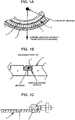
- Figs. 1A, 1B and 1C are a lateral diagram showing a main part, an enlarged cross-sectional diagram showing a magnetic ring unit and a diagram showing the relation between a sensor head unit and the magnetic ring unit respectively.
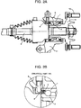
- Figs. 2A and 2B are an overall cross-sectional diagram showing an axis arm to which the encoder structure according to the present invention is adopted and an enlarged diagram showing a part B of Fig. 2A respectively.
- Fig. 3 is a perspective diagram showing a bearing to which the encoder structure according to the present invention is adopted.
- Fig. 1A, 1B and 1C are a lateral diagram showing a main part, an enlarged cross-sectional diagram showing a magnetic ring unit and a diagram showing the relation between a sensor head unit and the magnetic ring unit respectively.
- Figs. 2A and 2B are an overall cross-sectional diagram showing an
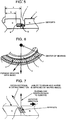
- FIG. 4 is an enlarged cross-sectional diagram that shows a magnetic ring unit regarding a second encoder structure which does not form part of the present invention.
- Fig. 5 is an enlarged cross-sectional diagram that shows a magnetic ring unit regarding a third encoder structure which does not form part of the present invention.
- Fig. 6 is a lateral diagram that shows a main part regarding a fourth encoder structure which does not form part of the present invention.
- Fig. 7 is an enlarged cross-sectional diagram that shows a magnetic ring unit regarding an embodiment of encoder structure according to the present invention.
- a basic configuration of the encoder structure which does not form part of the present invention, includes a rotative magnetic ring unit 4 that is positioned close to a sensor head unit 6 installed in an irrotational part and has N and S poles arranged alternately on the circumference.
- Such an encoder structure is characterized by forming a groove unit 7 in at least one of spaces between the N and S poles located on the surface of the magnetic ring unit 4.
- an encoder 3 is adopted to a sealing device for a bearing of a shaft.
- the adoption of the encoder 3 is not limited to the shaft, and may be applied to other parts where hermetic sealing is necessary and a rotational part and an irrotational part are close to each other.
- a wheel hub 10 is supported in an axial direction against a wheel housing 11, that is, the irrotational part is fixed to a vehicle body, by the bearing comprising an outer ring 1 and an inner ring 2 together holding balls therebetween.
- One end of a drive shaft 9 is combined with an inner side of the wheel hub 10 by a spline connection.
- a reference number "12" indicates a hub nut fixed to the wheel hub 10 and locks a wheel disk.
- the encoder 3 is positioned between one end of the outer ring 1 and the corresponding end of the inner ring 2 that are rotating relatively to each other, as shown in Fig. 2B or the enlarged diagram showing the part B of Fig. 2A .
- the encoder 3 comprises L-shaped retainers, each being fixed to the outer ring 1 and the inner ring 2 and positioned to face each other, in addition to a sealing unit 5 and the magnetic ring unit 4 fixed to each L-shaped retainer.
- the sealing unit 5 is positioned on the irrotational side
- the magnetic ring unit 4 is positioned on the rotational side.
- the sensor head unit 6 such as an ABS sensor mounted on the irrotational side of the wheel housing 11 is located close to the surface of the magnetic ring unit 4.
- Fig. 3 shows an encoder structure installed in a bearing device.
- the encoder 3 exposing the magnetic ring unit 4 is mounted at an end of spaces between the outer ring 1 and the inner ring 2 of the bearing device.
- Fig. 1A is the enlarged lateral diagram showing the main part of Fig. 3 , where the magnetic ring unit 4 comprises a plurality of the N and S poles arranged alternately.
- the arrangement of the N and S poles corresponds to radial lines from the center of the magnetic ring unit 4.
- a borderline between a N pole and a S pole is identical to a radial line from the center.
- the groove unit 7 is formed on each of the borderlines between the N and S poles as shown in Fig. 1B .
- the groove unit 7 is formed as a concave shaped groove whose cross-section is square-shaped in the present encoder. This groove unit 7 is preferably formed on each border as shown in Fig. 1C . However, formation of the groove unit 7 on all borders is unnecessary if accumulation of the iron particles or the like in the groove units 7 formed on some borders reduces a relative amount of deposits such as the iron particles on the other borders without groove unit 7, that is, if an interference by the deposits is inhibited in practical usage.
- the iron particles or the like adhere along a magnetic flux inside the groove unit 7 that is formed on the borderline between the N and S pole located on the surface of the magnetic ring unit 4, the iron particles or the like are easily drained away with flowing down muddy water by a gutter-like effect of the groove unit 7.
- Such effect is enhanced with a centrifugal force of a rotating wheel.
- the deposits accumulated inside the groove unit 7 can be effectively eliminated with the muddy water while the wheel is rotating according to a waterwheel-like effect caused by an edge of a sidewall of the groove unit 7.
- the groove unit 7 can maintain a clearance between the surface of the magnetic ring unit 4 and the sensor head unit 6 for an extended period of time because of the large capacity for the deposits, even if the iron particles or the like are accumulated inside the groove unit 7 after a long term operation. Accordingly, prevention of damage to the sensor head unit 6 is achieved, and thus, maintenance of detection precision of the sensor head unit 6 as a detecting device is ensured.
- Fig. 4 is an enlarged cross-sectional diagram showing the magnetic ring unit 4 regarding a second encoder structure, which does not form part of the present invention.
- the groove unit 7 is formed so that the cross section of the groove unit 7 is shaped like a horseshoe. Since the groove unit 7 has a circular configuration especially at its bottom corner by forming the cross-sectional shape of the groove unit 7 to a horseshoe shape, the deposits are hardly accumulated at the bottom corner. Additionally, the capacity of the groove unit 7 for the deposits can be determined by selecting the cross-sectional shape of the groove unit 7 from a V shape, a trapezoid, a half -arc shape or the like. Meanwhile, the durability of each magnetic ring unit 4 is ensured according to the shape-related characteristics based on the relation between the strength and durability of the magnetic ring unit 4 regarding formation of the groove unit 7.
- Fig. 5 is an enlarged cross-sectional diagram showing the magnetic ring unit 4 regarding a third encoder structure, which does not form part of the present invention.
- a circumferentially extending groove 8 is formed adjacently to the bottom of the groove unit 7 to have a key-shaped groove unit 13.
- the groove unit 7 is supposed to be formed so that the surface area of the magnetic ring unit 4 becomes an area "b".
- formation of the groove 8 secures the relatively large surface area "a" of the magnetic ring unit 4 and the large capacity for the deposits at the same time (a>b).
- the magnetic ring unit 4 can secure the relatively large surface area to acquire a high magnetic characteristic in spite of having the groove unit 7 and the groove 8.
- the gutter-like effect caused by the centrifugal force of a rotating wheel and a water-spitting-out effect caused by the waterwheel-like effect together enable easy elimination of the deposits inside the groove unit 7 and the groove 8 with the muddy water to reduce damage to the other parts.
- Fig. 6 is an enlarged lateral diagram showing the main part of the magnetic ring unit 4 regarding a fourth encoder structure, which does not form part of the present invention.
- the magnetic ring unit 4 is so structured that the arrangement of the N and S poles on the circumference is tilted at a predetermined angle with respect to radial lines from the center of the magnetic ring unit 4. Therefore, the borderlines between the N and S poles are tilted at the predetermined angle with respect to the radial lines, causing to form the groove unit 7 tilted at the predetermined angle with respect to the radial line. Accordingly, detection impulse by the sensor head unit 6 is reduced by making alteration of the magnetic poles smooth during the detection.
- the capacity for the deposits is increased by enlarging the length of the groove unit 7. Further, a draining ability of the groove unit 7 during mud water immersion is enhanced since a smooth flow of the mud water is achieved inside the groove unit 7 tilted toward a rotative direction of the magnetic ring unit 4.
- Fig. 7 is the enlarged cross-sectional diagram showing the magnetic ring unit 4 regarding an embodiment of the encoder structure according to the present invention.
- the present embodiment is characterized by forming the groove unit 7 so that a direction to divide the N pole and the S pole in the cross-sectional direction of the groove unit 7 is tilted at a predetermined angle with respect to a direction perpendicular to the surface of the magnetic ring unit 4.
- the groove unit 7 of the encoder is tilted toward a slotting direction, that is, a direction in which the deposits are eliminated by the rotation of the magnetic ring unit 4, by forming the groove unit 7 with some angle. Consequently, the ability of the groove unit 7 to drain the mud water is further improved, preventing the accumulation of the iron particles or the like inside the groove unit 7.
- the borderline between the N and S poles where the groove unit 7 is formed with the cross-section being tilted according to the present embodiment may correspond to the radial line from the center of the magnetic ring unit 4 as shown in Fig. 3 .
- this borderline may be tilted at a predetermined angle with respect to the radial line as shown in Fig. 6 .
- each encoder and of the embodiment according to the present invention in which a shape and a type of the following items may be arbitrarily selected without departing from the principle of operation.
- Such items are, for instance, usage of the encoder (an ABS sensor, a traction control system sensor, a speedometer, etc), the shape and the type (a reed switch, etc) of the sensor head unit 6, the shape and the type of the magnetic ring unit 4 of the encoder.
- the shape a V shape, a concave shape, a trapezoid, a horseshoe shape, an arc shape, a tilt angle, etc
- the forming position of the groove unit 7 the groove unit 7 may be formed to have an equal groove width on the N pole side and the S pole side of the borderline.
- the groove unit 7 may be so formed that one side of the borderline has a larger groove width than the other side.
- the circumferentially extending groove 8 of the key-shaped groove unit 13 may be formed on one side of the borderline.
- the circumferentially extending groove 8 may be formed on both sides of the borderline so that an actual shape of the key-shaped groove unit 13 becomes convex.
- the encoder structure is characterized by including the sensor head unit 6 installed in the irrotational part, the rotative magnetic ring unit 4 that is positioned close to the sensor head unit 6 and has the N and S poles arranged alternately on a circumference thereof, and the groove unit 7 formed in at least one of spaces between the N and S poles located on the surface of the magnetic ring unit 4.
- deposits such as the iron particles are easily drained away with the muddy water because a part along a magnetic flux where the iron particles tend to be accumulated functions as a groove-like path.
- accumulated iron particles remain inside the groove unit 7 that is concave shaped. Accordingly, the deposits hardly remain on the surface of the magnetic ring unit 4, preventing damage to the sensor head unit 6.
- the groove unit 7 is formed so that the direction to divide the N and S poles in the cross-sectional direction of the groove unit 7 is tilted at the predetermined angle with respect to the direction perpendicular to the surface of the magnetic ring unit 4. Therefore, an ability of the groove unit 7 to drain the mud water is further improved according to the cross-section of the groove unit 7 being tilted toward a slotting direction.
- the capacity of the groove unit 7 for the deposits is adjusted by selecting an appropriate shape of the groove unit 7 corresponding to characteristics of the magnetic ring unit 6. Accordingly, durability of the magnetic ring unit 6 is ensured according to the shape-related characteristics. Further, in a case that the circumferentially extending groove 6 is formed adjacently to the bottom of the groove unit 7 to have the key-shaped groove unit 13, a relatively large surface area of the encoder is secured to acquire the high magnetic characteristic in spite of having the groove unit 7. Additionally, the centrifugal force of the rotating wheel easily removes the deposits inside the groove unit 7, for preventing damage to other parts.
- detection impulse by the sensor head unit 6 can reduced by making alteration of the magnetic poles smooth. Additionally, the capacity for the deposits is increased by enlarging the length of the groove unit 7. Further, a draining ability of the groove unit 7 during the mud water immersion is enhanced since the smooth flow of the mud water is achieved inside the groove unit 7 tilted toward a rotative direction of the encoder.
Landscapes
- Engineering & Computer Science (AREA)
- General Engineering & Computer Science (AREA)
- Mechanical Engineering (AREA)
- Physics & Mathematics (AREA)
- General Physics & Mathematics (AREA)
- Transmission And Conversion Of Sensor Element Output (AREA)
- Regulating Braking Force (AREA)
- Sealing Of Bearings (AREA)
- Rolling Contact Bearings (AREA)
Claims (4)
- Geberstruktur (3), die Folgendes umfasst:eine Sensorkopfeinheit (6), die in einem drehungsfreien Teil installiert ist;eine drehende Magnetringeinheit (4), die nah bei der Sensorkopfeinheit (6) positioniert ist und einen Nordpol und einen Südpol aufweist, die abwechselnd an einem Umfang davon angeordnet sind; undeine in mindestens einem Zwischenraum zwischen einem Nordpol und einem benachbarten Südpol gebildete Rilleneinheit (7), die sich an einer Oberfläche der Magnetringeinheit befindet,dadurch gekennzeichnet, dass die Rilleneinheit derart gebildet ist, dass die Richtung der den Nordpol und den Südpol in einer Querschnittsrichtung der Rilleneinheit trennenden Rilleneinheit um einen vorherbestimmten Winkel in Bezug auf die zur Oberfläche der Magnetringeinheit senkrechte Richtung geneigt ist.
- Geberstruktur nach Anspruch 1, dadurch gekennzeichnet, dass
eine Querschnittsform der Rilleneinheit (7) aus einer V-Form, einer konkaven Form, einem Trapezoid und einer Hufeisenform ausgewählt ist. - Geberstruktur nach Anspruch 1 oder 2, dadurch gekennzeichnet, dass
eine sich in Umfangsrichtung erstreckende Rille (8) einem Boden der Rilleneinheit benachbart gebildet ist, um eine schlüsselförmige Rilleneinheit zu erhalten. - Geberstruktur nach einem der Ansprüche 1 bis 3, dadurch gekennzeichnet, dass
eine Anordnung des Nordpols und des Südpols an dem Umfang um einen vorherbestimmten Winkel in Bezug auf eine Radiallinie von einer Mitte der Magnetringeinheit geneigt ist.
Applications Claiming Priority (2)
| Application Number | Priority Date | Filing Date | Title |
|---|---|---|---|
| JP2003398986A JP4417080B2 (ja) | 2003-11-28 | 2003-11-28 | エンコーダシール構造 |
| JP2003398986 | 2003-11-28 |
Publications (3)
| Publication Number | Publication Date |
|---|---|
| EP1536239A2 EP1536239A2 (de) | 2005-06-01 |
| EP1536239A3 EP1536239A3 (de) | 2012-01-04 |
| EP1536239B1 true EP1536239B1 (de) | 2017-03-01 |
Family
ID=34463873
Family Applications (1)
| Application Number | Title | Priority Date | Filing Date |
|---|---|---|---|
| EP04257298.2A Expired - Lifetime EP1536239B1 (de) | 2003-11-28 | 2004-11-24 | Drehgeberstruktur |
Country Status (3)
| Country | Link |
|---|---|
| US (1) | US20050116707A1 (de) |
| EP (1) | EP1536239B1 (de) |
| JP (1) | JP4417080B2 (de) |
Families Citing this family (10)
| Publication number | Priority date | Publication date | Assignee | Title |
|---|---|---|---|---|
| EP1983306B1 (de) | 2006-01-23 | 2014-04-02 | JTEKT Corporation | Rotor für einen drehcodierer und wälzlager für ein rad damit |
| US7455459B2 (en) * | 2006-03-09 | 2008-11-25 | Federal Mogul World Wide, Inc. | Oil bath encoder seal |
| JP2008157900A (ja) * | 2006-11-30 | 2008-07-10 | Nok Corp | 磁気エンコーダ |
| DE102007022675A1 (de) * | 2007-05-15 | 2008-11-20 | Schaeffler Kg | Dichtungsanordnung für ein Wälzlager |
| DE102007029511A1 (de) * | 2007-06-26 | 2009-01-02 | Schaeffler Kg | Verwendung eines Lagerkäfigs bzw. eines Lagerrings |
| CN102538835A (zh) * | 2010-12-20 | 2012-07-04 | 长春荣德光学有限公司 | 非接触圆环形磁电旋转编码器 |
| WO2013001329A1 (en) * | 2011-06-28 | 2013-01-03 | Aktiebolaget Skf | Sealed bearing assembly with magnet on sealing disc to attract metallic particles |
| FR2988149B1 (fr) * | 2012-03-15 | 2014-12-26 | Ntn Snr Roulements | Unite de roulement comprenant des moyens de filtration magnetique. |
| EP3025125B1 (de) | 2013-07-23 | 2018-03-21 | Balluff GmbH | Verfahren zur dynamischen linearisierung von sensorsignalen eines magnetband-längenmesssystems |
| JP6200469B2 (ja) * | 2015-08-28 | 2017-09-20 | ファナック株式会社 | 液密構造を有するエンコーダ |
Family Cites Families (5)
| Publication number | Priority date | Publication date | Assignee | Title |
|---|---|---|---|---|
| DE2709412A1 (de) * | 1977-03-04 | 1978-09-07 | Max Baermann | Wirbelstromtachometer mit temperaturkompensation |
| JPH067056B2 (ja) | 1988-04-06 | 1994-01-26 | 日本ビクター株式会社 | 位置及び速度検出装置 |
| JP3397026B2 (ja) * | 1995-12-06 | 2003-04-14 | トヨタ自動車株式会社 | 磁気式回転検出装置 |
| JP4024496B2 (ja) | 2001-07-25 | 2007-12-19 | Ntn株式会社 | 磁気エンコーダおよびこれを具備する車輪用軸受 |
| EP1291660A3 (de) | 2001-09-11 | 2003-05-28 | Koyo Seiko Co., Ltd. | Impulsring, Magnetisierungsvorrichtung und Verfahren, sowie Lager mit magnetischem Impulsring |
-
2003
- 2003-11-28 JP JP2003398986A patent/JP4417080B2/ja not_active Expired - Fee Related
-
2004
- 2004-11-23 US US10/994,266 patent/US20050116707A1/en not_active Abandoned
- 2004-11-24 EP EP04257298.2A patent/EP1536239B1/de not_active Expired - Lifetime
Non-Patent Citations (1)
| Title |
|---|
| None * |
Also Published As
| Publication number | Publication date |
|---|---|
| JP4417080B2 (ja) | 2010-02-17 |
| EP1536239A2 (de) | 2005-06-01 |
| EP1536239A3 (de) | 2012-01-04 |
| JP2005156498A (ja) | 2005-06-16 |
| US20050116707A1 (en) | 2005-06-02 |
Similar Documents
| Publication | Publication Date | Title |
|---|---|---|
| US6682076B1 (en) | Combination seal ring encoder | |
| CN101415964B (zh) | 密封装置 | |
| KR950000923B1 (ko) | 속도 감지기가 설치된 베어링 조립체 | |
| US6605938B1 (en) | Compact wheel speed detector capable of saving space and improving workability | |
| JP2752343B2 (ja) | パッキン装置 | |
| EP1536239B1 (de) | Drehgeberstruktur | |
| JP4411911B2 (ja) | 密封装置 | |
| WO2008018765A1 (en) | Seal integrated with encoder for bearing | |
| US9377055B2 (en) | Wheel bearing arrangement with encoder protection and centering device | |
| EP1431071A2 (de) | Wälzlagervorrichtung | |
| JP2002286739A (ja) | 回転センサ用ローター | |
| CN101416030A (zh) | 转子编码器用脉冲发生环 | |
| US7926816B2 (en) | Sealing device with tone wheel | |
| EP1351059A2 (de) | Fahrzeugachseinheit | |
| JP2001241435A (ja) | 自動車用エンコーダ付転がり軸受ユニット | |
| US7034524B2 (en) | Measuring device for the angle of rotation of a rotating machine member | |
| JP4604388B2 (ja) | エンコーダ付組み合わせシールリングを備えた転がり軸受ユニット | |
| US5998987A (en) | Structure for mounting a wheel revolution detecting device | |
| US20030223665A1 (en) | Protective device for antifriction bearing with rotational speed measurement | |
| PL185317B1 (pl) | Zespół czujnika prędkości kątowej koła pojazdu | |
| JP2570938Y2 (ja) | 回転検出装置付き密封装置 | |
| US20090051354A1 (en) | Pulsar ring for magnetic encoder | |
| JP4105379B2 (ja) | 車輪用軸受 | |
| JP2007333188A (ja) | 回転速度検出機構回転速度検出機構を備えた転がり軸受及び車輪支持用軸受ユニット | |
| JP4622185B2 (ja) | エンコーダ及びエンコーダ付転がり軸受ユニット |
Legal Events
| Date | Code | Title | Description |
|---|---|---|---|
| PUAI | Public reference made under article 153(3) epc to a published international application that has entered the european phase |
Free format text: ORIGINAL CODE: 0009012 |
|
| AK | Designated contracting states |
Kind code of ref document: A2 Designated state(s): AT BE BG CH CY CZ DE DK EE ES FI FR GB GR HU IE IS IT LI LU MC NL PL PT RO SE SI SK TR |
|
| AX | Request for extension of the european patent |
Extension state: AL HR LT LV MK YU |
|
| PUAL | Search report despatched |
Free format text: ORIGINAL CODE: 0009013 |
|
| AK | Designated contracting states |
Kind code of ref document: A3 Designated state(s): AT BE BG CH CY CZ DE DK EE ES FI FR GB GR HU IE IS IT LI LU MC NL PL PT RO SE SI SK TR |
|
| AX | Request for extension of the european patent |
Extension state: AL HR LT LV MK YU |
|
| RIC1 | Information provided on ipc code assigned before grant |
Ipc: G01P 3/487 20060101AFI20111125BHEP Ipc: G01D 5/245 20060101ALI20111125BHEP Ipc: G01D 5/244 20060101ALI20111125BHEP |
|
| 17P | Request for examination filed |
Effective date: 20120326 |
|
| 17Q | First examination report despatched |
Effective date: 20120621 |
|
| AKX | Designation fees paid |
Designated state(s): DE |
|
| RAP1 | Party data changed (applicant data changed or rights of an application transferred) |
Owner name: FUJI JUKOGYO KABUSHIKI KAISHA |
|
| GRAP | Despatch of communication of intention to grant a patent |
Free format text: ORIGINAL CODE: EPIDOSNIGR1 |
|
| RIC1 | Information provided on ipc code assigned before grant |
Ipc: F16C 41/00 20060101ALI20160803BHEP Ipc: G01D 5/244 20060101ALI20160803BHEP Ipc: F16C 33/78 20060101ALI20160803BHEP Ipc: F16C 19/18 20060101ALI20160803BHEP Ipc: G01D 5/245 20060101ALI20160803BHEP Ipc: F16C 33/66 20060101ALI20160803BHEP Ipc: G01P 3/487 20060101AFI20160803BHEP |
|
| INTG | Intention to grant announced |
Effective date: 20160908 |
|
| GRAJ | Information related to disapproval of communication of intention to grant by the applicant or resumption of examination proceedings by the epo deleted |
Free format text: ORIGINAL CODE: EPIDOSDIGR1 |
|
| GRAR | Information related to intention to grant a patent recorded |
Free format text: ORIGINAL CODE: EPIDOSNIGR71 |
|
| GRAS | Grant fee paid |
Free format text: ORIGINAL CODE: EPIDOSNIGR3 |
|
| GRAA | (expected) grant |
Free format text: ORIGINAL CODE: 0009210 |
|
| INTC | Intention to grant announced (deleted) | ||
| AK | Designated contracting states |
Kind code of ref document: B1 Designated state(s): DE |
|
| INTG | Intention to grant announced |
Effective date: 20170120 |
|
| REG | Reference to a national code |
Ref country code: DE Ref legal event code: R081 Ref document number: 602004050821 Country of ref document: DE Owner name: SUBARU CORPORATION, JP Free format text: FORMER OWNER: FUJI JUKOGYO K.K., TOKIO/TOKYO, JP |
|
| REG | Reference to a national code |
Ref country code: DE Ref legal event code: R096 Ref document number: 602004050821 Country of ref document: DE |
|
| REG | Reference to a national code |
Ref country code: DE Ref legal event code: R082 Ref document number: 602004050821 Country of ref document: DE Representative=s name: WP THOMPSON, GB Ref country code: DE Ref legal event code: R081 Ref document number: 602004050821 Country of ref document: DE Owner name: SUBARU CORPORATION, JP Free format text: FORMER OWNER: FUJI JUKOGYO K.K., TOKYO, JP |
|
| RAP2 | Party data changed (patent owner data changed or rights of a patent transferred) |
Owner name: SUBARU CORPORATION |
|
| REG | Reference to a national code |
Ref country code: DE Ref legal event code: R097 Ref document number: 602004050821 Country of ref document: DE |
|
| PLBE | No opposition filed within time limit |
Free format text: ORIGINAL CODE: 0009261 |
|
| STAA | Information on the status of an ep patent application or granted ep patent |
Free format text: STATUS: NO OPPOSITION FILED WITHIN TIME LIMIT |
|
| 26N | No opposition filed |
Effective date: 20171204 |
|
| PGFP | Annual fee paid to national office [announced via postgrant information from national office to epo] |
Ref country code: DE Payment date: 20191121 Year of fee payment: 16 |
|
| REG | Reference to a national code |
Ref country code: DE Ref legal event code: R119 Ref document number: 602004050821 Country of ref document: DE |
|
| PG25 | Lapsed in a contracting state [announced via postgrant information from national office to epo] |
Ref country code: DE Free format text: LAPSE BECAUSE OF NON-PAYMENT OF DUE FEES Effective date: 20210601 |