EP1536195A2 - Eiserzeuger für einen Kühlschrank - Google Patents
Eiserzeuger für einen Kühlschrank Download PDFInfo
- Publication number
- EP1536195A2 EP1536195A2 EP04105470A EP04105470A EP1536195A2 EP 1536195 A2 EP1536195 A2 EP 1536195A2 EP 04105470 A EP04105470 A EP 04105470A EP 04105470 A EP04105470 A EP 04105470A EP 1536195 A2 EP1536195 A2 EP 1536195A2
- Authority
- EP
- European Patent Office
- Prior art keywords
- ice
- heater body
- mold
- icemaker
- ice mold
- Prior art date
- Legal status (The legal status is an assumption and is not a legal conclusion. Google has not performed a legal analysis and makes no representation as to the accuracy of the status listed.)
- Withdrawn
Links
Images




Classifications
-
- F—MECHANICAL ENGINEERING; LIGHTING; HEATING; WEAPONS; BLASTING
- F25—REFRIGERATION OR COOLING; COMBINED HEATING AND REFRIGERATION SYSTEMS; HEAT PUMP SYSTEMS; MANUFACTURE OR STORAGE OF ICE; LIQUEFACTION SOLIDIFICATION OF GASES
- F25C—PRODUCING, WORKING OR HANDLING ICE
- F25C1/00—Producing ice
- F25C1/22—Construction of moulds; Filling devices for moulds
- F25C1/24—Construction of moulds; Filling devices for moulds for refrigerators, e.g. freezing trays
-
- F—MECHANICAL ENGINEERING; LIGHTING; HEATING; WEAPONS; BLASTING
- F25—REFRIGERATION OR COOLING; COMBINED HEATING AND REFRIGERATION SYSTEMS; HEAT PUMP SYSTEMS; MANUFACTURE OR STORAGE OF ICE; LIQUEFACTION SOLIDIFICATION OF GASES
- F25C—PRODUCING, WORKING OR HANDLING ICE
- F25C5/00—Working or handling ice
- F25C5/02—Apparatus for disintegrating, removing or harvesting ice
- F25C5/04—Apparatus for disintegrating, removing or harvesting ice without the use of saws
- F25C5/08—Apparatus for disintegrating, removing or harvesting ice without the use of saws by heating bodies in contact with the ice
-
- F—MECHANICAL ENGINEERING; LIGHTING; HEATING; WEAPONS; BLASTING
- F25—REFRIGERATION OR COOLING; COMBINED HEATING AND REFRIGERATION SYSTEMS; HEAT PUMP SYSTEMS; MANUFACTURE OR STORAGE OF ICE; LIQUEFACTION SOLIDIFICATION OF GASES
- F25C—PRODUCING, WORKING OR HANDLING ICE
- F25C5/00—Working or handling ice
- F25C5/20—Distributing ice
- F25C5/22—Distributing ice particularly adapted for household refrigerators
-
- F—MECHANICAL ENGINEERING; LIGHTING; HEATING; WEAPONS; BLASTING
- F25—REFRIGERATION OR COOLING; COMBINED HEATING AND REFRIGERATION SYSTEMS; HEAT PUMP SYSTEMS; MANUFACTURE OR STORAGE OF ICE; LIQUEFACTION SOLIDIFICATION OF GASES
- F25C—PRODUCING, WORKING OR HANDLING ICE
- F25C1/00—Producing ice
- F25C1/22—Construction of moulds; Filling devices for moulds
-
- F—MECHANICAL ENGINEERING; LIGHTING; HEATING; WEAPONS; BLASTING
- F25—REFRIGERATION OR COOLING; COMBINED HEATING AND REFRIGERATION SYSTEMS; HEAT PUMP SYSTEMS; MANUFACTURE OR STORAGE OF ICE; LIQUEFACTION SOLIDIFICATION OF GASES
- F25C—PRODUCING, WORKING OR HANDLING ICE
- F25C2305/00—Special arrangements or features for working or handling ice
- F25C2305/024—Rotating rake
-
- F—MECHANICAL ENGINEERING; LIGHTING; HEATING; WEAPONS; BLASTING
- F25—REFRIGERATION OR COOLING; COMBINED HEATING AND REFRIGERATION SYSTEMS; HEAT PUMP SYSTEMS; MANUFACTURE OR STORAGE OF ICE; LIQUEFACTION SOLIDIFICATION OF GASES
- F25C—PRODUCING, WORKING OR HANDLING ICE
- F25C2400/00—Auxiliary features or devices for producing, working or handling ice
- F25C2400/10—Refrigerator units
Definitions
- the present invention relates to an icemaker for a refrigerator, and more particularly, to an icemaker for a refrigerator, which can quickly separate pieces of ice therefrom by uniformly heating a surface where the pieces of ice contact an ice mold.
- FIG. 1 shows a refrigerator according to the related art.
- a refrigerator comprises a barrier 1 for dividing an inner space into a chilling compartment and a freezing compartment, a main body 2 in which a cooling cycle device for maintaining the chilling and freezing compartments at a low temperature is installed, a freezing door 4 pivotally mounted on the main body 2 to open and clos e the freezing compartment, and a chilling door 6 pivotally mounted on the main body 2 to open and close the chilling compartment.
- the cooling cycle device applied to the refrigerator includes a compressor (not shown) for compressing low temperature/low pressure gas refrigerant, a condenser (not shown) for condensing the compressed refrigerant, an expanding device for reducing pressure of the condensed refrigerant, and a vaporizer for vaporizing the expanded refrigerant while absorbing heat of the chilling and freezing compartments.
- the automatic ice machine includes an icemaker 7 for freezing water fed thereto and an ice bank 20 for storing pieces of ice separated from the icemaker 7, a dispenser 300 installed on the freezing door 4 to allow the pieces of ice to be dispensed even without opening the freezing door 4, and an ice chu te 40 for directing the pieces of ice from the ice bank 20 to the dispense 30.
- a heating wir e is arranged on an outer surface of the icemaker in a predetermined pattern where lines are spaced away from each other at a predetermined distance.
- the heating wire When power is applied to the heating wire, the heating wire generates Joule heat to melt a portion of ice at a portion where the ice contacts the icemaker so that the ice can be effectively separated from the icemaker.
- U.S. Patent No. 6,705,091 assigned to the applicant of this invention discloses such an icemaker with the heating wire.
- the present invention is directed to an icemaker for a refrigerator that substantially obviates one or more problems due to limitations and disadvantages of the related art.
- An object of the present invention is to provide an icemaker that can quickly separate pieces of heating a surface of an ice mold, thereby making pieces of ice that are formed in an identical shape and saving the time for making the ice.
- an icemaker for a refrigerator comprises an ice mold for receiving water and freezing the water to ice; an ejector pivotally installed on the ice mold to eject the ice out of the ice mold; a motor for operating the ejector; a heater body disposed enclosing the ice mold to separate the ice from an inner surface of the ice mold by uniformly heating the ice mold; and a heating coil for applying induced electromotive power to the heater body, thereby allowing the heater body to generate heat.
- an icemaker for a refrigerator comprising an ice mold for receiving water and freezing the water to ice; and a heater for separating the ice from an inner surface of the ice mold by uniformly heating a surface where the ice contacts the inner surface of the ice mold using an induction heating manner by an induced electromotive power applied form an external side.
- an icemaker for a refrigerator comprising an ice mold for receiving water and freezing the water to ice; and a heater for separating the ice from an inner surface of the ice mold by uniformly heating an entire surface of the ice mold.
- Fig. 1 is a refrigerator according to the related art
- Fig. 2 is a perspective view of an icemaker according to an embodiment of the present invention.
- Fig. 3 is a partially broken perspective view of an icemaker according to an embodiment of the present invention.
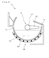
- Fig. 4 is a sectional view taken along line A -A' of Fig. 2;
- Fig. 5 is a view illustrating an induction heating principle
- Fig. 6 is a hysteresis loop according to an induction heating
- Figs. 7 and 8 are views illustrating a process for separating ice from an icemaker using a heater.
- Figs. 2 and 3 show an icemaker according to an embodiment of the present invention.
- an icemaker 10 comprises a cup 11 for storing water fed from a water supply hose (not shown), an ice mold 12 for receiving the water from the cup 11 and freezing the water using cool air in a freezing compartmen t, a heater 130 for heating the ice mold 12 to separate pieces of the ice, the heater 130 being mounted on the ice mold 12, an ejector 14 for ejecting the pieces of the ice out of the ice mold 12, the ejector 14 being pivotally mounted on the ice mold 14, a motor (not shown) for generating torque for driving the ejector 14, a slider 16 for directing the pieces of the ice ejected by the ejector 14 to the ice bank 20, a detecting lever 17 for detecting the ice bank 20 fully filled with the pieces of the ice, a controller 18 for, in accordance with whether the ice bank 20 is fully filled with the pieces of the ice, controlling a temperature of the ice mold 12, the operations of the heater 130, the motor
- the ice mold 12 is provided with a space in which the water is frozen and a plurality of partition 121 for dividing the space into a plurality of freezing sections to make the pieces of the ice.
- the ice mold 12 is further provided at a rear en d with connection parts 122 for fixing the icemaker 10 on a rear wall of the freezing compartment.
- the ejector 14 comprises a pivoting shaft 141 installed on the ice mold 12 and pivoted by the torque of the motor and a plurality of scoops 142 extending fro m the pivoting shaft 141.
- the number of the scoops 142 is identical to that of the freezing sections divided by the partitions 121.
- the scoops 142 are located in the respective freezing sections to scoop the corresponding pieces of the ice out of the freezing sections.
- the motor is installed in the controller 18 disposed on a side of the ice mold 12 and is connected to the pivoting shaft 141.
- the controller 18 may be provided with a temperature sensor for detecting a temperature of the ice mold 12 and an ice detecting sensor for detecting a rotating position of the detecting lever 17 to determine if the ice bank is fully filled with the pieces of the ice.
- the heater 130 may be formed of an induction heater that can uniformly heat the ice mold 12.
- the water is first fed to the ice mold 12 via the cup 11 and is then frozen, after which a surface of the frozen water is uniformly heated by the heater 130 such that the pieces of the ice can be separated at a surface where they contact the ice mold 12. Then, the pieces of the ice are ejected out of the ice mold. That is, as the pivoting shaft 141 pivots, the pieces of the ice are scooped by the scoops 142. The scooped pieces of the ice are stacked in the ice bank 20 along the slider 16.
- Fig. 4 is a sectional view taken along line A -A' of Fig. 2.
- the heater 130 is disposed on a circumferential outer bottom of the ice mold 12.
- the heater 130 is designed to be heated by an induction heating manner.
- the heater 130 comprises a heating coil generating eddy current by high frequency current applied from an external side to convert the electric energy into the thermal and a heater body 134 in which the heating coil is buried, the heater body 134 being formed in a circular arc shape to enclose the circumferential outer bottom of the ice mold 12.
- the heater body 134 separates the pieces of the ice 21 fr om the inner surface of the ice mold 12 using induction energy inducted from the heating coil 132.
- Fig. 5 is a view illustrating an induction heating principle
- Fig. 6 is a hysteresis loop according to an induction heating.
- an electric conductor in a coil along which alternating current (high frequency current) flows generates heat by an eddy current loss and a hysteresis loss (in case of a magnetic body). That is, the induction heating is realized by such heat generated by the eddy current loss and the hysteresis loss.
- a high frequency induction heating uses high frequency current.
- alternating magnetic flux (high frequency magnetic flux) is generated in a coil along which alternating current (high frequency current) i1 and induced current (induced electromotive force) is generated in the electric conductor in a magnetic field.
- the current generated by the electromotive force is called eddy current.
- the electric conductor When the eddy current flows along the electric conductor (to-be-heated-object) having a predetermined amount of resistance, the electric conductor generates the Jo ule heat. This is called the eddy current loss that will be a primary heat source in the induction heating.
- the eddy current loss can be illustrated as the following formula according to Joule's law.
- the eddy current loss is proportional to the square of the frequency. Therefore, when the frequency is higher than 100 kHz, the heating is realized by the eddy current loss. When the frequency is les s than 100 kHz, the heating is realized by the hysteresis loss.
- the to-be-heated-object When the to-be-heated-object is formed of magnetic material and alternating current is applied to a heating coil wound around the to-be-heated object, the to-be-heated-object is magnetized. At this point, when intensity of the magnetic field is gradually increased, a curve representing the variation of the magnetic flux density B is not identical to that representing the magnetic field intensity H. That is, as shown in Fig. 6, a loop shape is defined by the curves, providing a hysteresis phenomenon. This loop shape is called a hysteresis loop.
- Wh nh f Bm1.6 6 (wb/m 2 ) (nh: a constant of applied metal core, f: frequency, and Bm: magnetic flux den sity)
- the heating body 134 functions as the electric conductor along which induced current flows when alternating current is applied to the heating coil 132.
- Fig. 7 shows a heating process by the heater 130 before the ejector 14 is operated
- Fig. 8 shows an ejecting process by the ejector 14 after the ice is separated from the inner surface of the ice mold 12.
- the adhering portion of the ice to the inner surface of the ice mold 12 uniformly melts, making it easy to quickly separate the ice from the ice mold 12.
- the ice mold 12 is uniformly heated by the induction heating manner, the ice 21 can be more quickly separated from the ice mold 12.
- the shaft 141 of the ejector 14 is rotated by the motor such that the scoop 142 can scoop the ice 21 out of the ice mold 12, thereby directing the ice 21 to the ice bank 20.
- the heating coil 132 is buried in the heater body 134.
- the present invention is not limited to this case. That is, the heating coil 132 may be formed on a surface of the heater body 134 in a predetermined pattern.
- the heater body 134 is formed of metal havi ng a predetermined amount of resistance, and the heating coil 132 is formed in a predetermined pattern having a uniformly spaced line through the entire area of the heater body 134.
- the heater body 134 is designed corresponding to the circumf erential outer bottom of the ice mold 12 so that the heat conduction can be quickly realized.
- the heat generated by induction heating can be directly transmitted to the ice, making it pos sible to more quickly make the ice.
- the induced heating coil may be directly formed on an outer surface of the ice mold 12.
- the above-described icemaker can be applied to a side - by-side type refrigerator as well as freeze -top-type refrigerator.
- the pieces of the ice 21 can be more quickly separated from the ice mold 12, being formed in an identical shape.
- the elect ric power used for the ice separation as well as the ice making time can be saved.
Landscapes
- Engineering & Computer Science (AREA)
- Physics & Mathematics (AREA)
- Mechanical Engineering (AREA)
- Thermal Sciences (AREA)
- General Engineering & Computer Science (AREA)
- Production, Working, Storing, Or Distribution Of Ice (AREA)
- Secondary Cells (AREA)
- Moulds For Moulding Plastics Or The Like (AREA)
Applications Claiming Priority (2)
| Application Number | Priority Date | Filing Date | Title |
|---|---|---|---|
| KR2003085208 | 2003-11-27 | ||
| KR1020030085208A KR100693578B1 (ko) | 2003-11-27 | 2003-11-27 | 냉장고용 아이스 메이커 |
Publications (2)
| Publication Number | Publication Date |
|---|---|
| EP1536195A2 true EP1536195A2 (de) | 2005-06-01 |
| EP1536195A3 EP1536195A3 (de) | 2006-10-25 |
Family
ID=34464764
Family Applications (1)
| Application Number | Title | Priority Date | Filing Date |
|---|---|---|---|
| EP04105470A Withdrawn EP1536195A3 (de) | 2003-11-27 | 2004-11-03 | Eiserzeuger für einen Kühlschrank |
Country Status (5)
| Country | Link |
|---|---|
| US (1) | US7493776B2 (de) |
| EP (1) | EP1536195A3 (de) |
| JP (1) | JP2005156139A (de) |
| KR (1) | KR100693578B1 (de) |
| CN (1) | CN1325863C (de) |
Cited By (1)
| Publication number | Priority date | Publication date | Assignee | Title |
|---|---|---|---|---|
| DE102012218349A1 (de) * | 2012-10-09 | 2014-04-10 | Hochschule Karlsruhe-Technik Und Wirtschaft | Vorrichtung und Verfahren zur Erzeugung von Eisbrei |
Families Citing this family (28)
| Publication number | Priority date | Publication date | Assignee | Title |
|---|---|---|---|---|
| KR100671567B1 (ko) * | 2004-05-18 | 2007-01-18 | 엘지전자 주식회사 | 냉장고용 제빙기의 만빙 감지 장치 |
| KR100642362B1 (ko) * | 2004-11-02 | 2006-11-03 | 엘지전자 주식회사 | 제빙기의 급수량 제어장치 및 제어방법 |
| DE102005003236A1 (de) * | 2005-01-24 | 2006-07-27 | BSH Bosch und Siemens Hausgeräte GmbH | Eisbereiter, Tablett dafür und Verfahren zur Eisherstellung |
| KR100808171B1 (ko) * | 2005-12-16 | 2008-03-03 | 엘지전자 주식회사 | 제빙장치 및 그 제어방법 |
| KR100863389B1 (ko) * | 2006-08-24 | 2008-10-13 | 엘지전자 주식회사 | 냉장고 및 냉장고의 제빙 장치 |
| US9166989B2 (en) | 2006-12-28 | 2015-10-20 | Hewlett-Packard Development Company, L.P. | Storing log data efficiently while supporting querying |
| US20080155997A1 (en) * | 2006-12-29 | 2008-07-03 | Whirlpool Corporation | Refrigerated drawer having an icemaker |
| US7757511B2 (en) * | 2006-12-29 | 2010-07-20 | Whirlpool Corporation | Refrigerated drawer having an icemaker |
| KR20090019322A (ko) * | 2007-08-20 | 2009-02-25 | 엘지전자 주식회사 | 제빙 장치 및 이를 적용한 냉장고 |
| US7900470B2 (en) * | 2007-12-07 | 2011-03-08 | General Electric Company | Automatic icemaker |
| US20090211266A1 (en) * | 2008-02-27 | 2009-08-27 | Young Jin Kim | Method of controlling ice making assembly for refrigerator |
| US8434321B2 (en) * | 2008-02-27 | 2013-05-07 | Lg Electronics Inc. | Ice making assembly for refrigerator and method for controlling the same |
| KR20090092384A (ko) * | 2008-02-27 | 2009-09-01 | 엘지전자 주식회사 | 냉장고용 제빙 어셈블리 및 제빙 어셈블리의 수위 감지방법 |
| KR101480549B1 (ko) * | 2008-02-28 | 2015-01-08 | 엘지전자 주식회사 | 냉장고의 제빙장치 및 그 제어방법 |
| KR101457691B1 (ko) * | 2008-03-10 | 2014-11-03 | 엘지전자 주식회사 | 냉장고용 제빙 어셈블리의 제어 방법 |
| US9029743B2 (en) * | 2008-08-22 | 2015-05-12 | General Electric Company | Heating apparatus for an appliance |
| JP5014310B2 (ja) * | 2008-11-04 | 2012-08-29 | 三菱電機株式会社 | 自動製氷装置及びこれを備えた冷蔵庫 |
| DE102008054496A1 (de) * | 2008-12-10 | 2010-06-17 | BSH Bosch und Siemens Hausgeräte GmbH | Eiswürfelbehälter eines Eiswürfelbereiters für Haushaltszwecke und Kältegerät mit einem solchen Eiswürfelbehälter |
| US8539780B2 (en) | 2010-06-28 | 2013-09-24 | General Electric Company | Method and apparatus for harvesting ice in an ice maker system |
| CN102620495B (zh) * | 2012-04-06 | 2013-09-25 | 浙江大学 | 一种制冰控制方法及制冰系统 |
| WO2014092329A1 (ko) * | 2012-12-10 | 2014-06-19 | 주식회사 대창 | 제빙기 |
| US10267550B2 (en) * | 2014-07-23 | 2019-04-23 | Dae Chang Co., Ltd. | Tray for ice making machine, ice making machine comprising same, and refrigerator comprising ice making machine |
| WO2017132047A1 (en) * | 2016-01-29 | 2017-08-03 | Illinois Tool Works, Inc. | Smart ice system |
| CN110050165B (zh) * | 2016-12-16 | 2020-10-09 | 三菱电机株式会社 | 制冰装置及冰箱 |
| US10823475B2 (en) * | 2018-09-19 | 2020-11-03 | Haier Us Appliance Solutions, Inc. | Clear barrel ice maker |
| CN109213391B (zh) | 2018-09-25 | 2020-11-17 | 京东方科技集团股份有限公司 | 一种触控显示面板及其制作方法、显示装置 |
| KR102823935B1 (ko) * | 2018-11-16 | 2025-06-23 | 엘지전자 주식회사 | 아이스 메이커 및 이를 구비하는 냉장고 |
| CN116928105A (zh) * | 2023-08-29 | 2023-10-24 | 无锡威孚高科技集团股份有限公司 | 一种具有自加热化冰功能的氢泵 |
Family Cites Families (33)
| Publication number | Priority date | Publication date | Assignee | Title |
|---|---|---|---|---|
| US2522507A (en) * | 1946-08-30 | 1950-09-19 | Flakice Corp | Ice-making apparatus |
| US3020730A (en) * | 1959-08-03 | 1962-02-13 | Water Process Corp | Ice making apparatus |
| US3163017A (en) * | 1961-07-24 | 1964-12-29 | Borg Warner | Ice cube maker having bin control |
| US3318105A (en) * | 1965-09-30 | 1967-05-09 | Borg Warner | Method and apparatus for producing clear ice under quiescent conditions |
| US3775992A (en) * | 1972-07-17 | 1973-12-04 | Gen Motors Corp | Method and apparatus for making clear ice |
| US3875370A (en) * | 1974-03-07 | 1975-04-01 | Standex Int Corp | Heat-retaining food service unit |
| DE8018995U1 (de) | 1980-07-15 | 1980-10-23 | Bosch-Siemens Hausgeraete Gmbh, 7000 Stuttgart | Geschirrspuelmaschine |
| US4450347A (en) * | 1980-11-12 | 1984-05-22 | Battelle Memorial Institute | Heating body |
| US4388521A (en) * | 1981-07-02 | 1983-06-14 | Ryder International Corporation | Modular disinfector device |
| US5286952A (en) * | 1987-06-11 | 1994-02-15 | Raychem Corporation | Methods and devices which make use of conductive polymers to join articles |
| US4833894A (en) * | 1988-05-02 | 1989-05-30 | Whirlpool Corporation | Ice maker with overtemperature protection |
| US4923494A (en) * | 1988-10-17 | 1990-05-08 | Eaton Corporation | Making ice in a refrigerator |
| US5056322A (en) * | 1991-01-04 | 1991-10-15 | Mid-South Industries, Inc. | Half crescent shaped ice piece maker |
| JPH05203302A (ja) | 1992-01-30 | 1993-08-10 | Matsushita Refrig Co Ltd | 自動製氷装置 |
| US5160094A (en) * | 1992-02-24 | 1992-11-03 | Whirlpool Corporation | Recoverable domestic ice maker |
| US5582754A (en) * | 1993-12-08 | 1996-12-10 | Heaters Engineering, Inc. | Heated tray |
| KR970002653B1 (ko) * | 1993-12-16 | 1997-03-07 | 엘지전자 주식회사 | 냉장고 |
| US5408844A (en) * | 1994-06-17 | 1995-04-25 | General Electric Company | Ice maker subassembly for a refrigerator freezer |
| DE4430418C1 (de) | 1994-08-26 | 1995-10-26 | Henkel Ecolab Gmbh & Co Ohg | Verfahren und Gerät zum Dosieren eines pastenartigen Waschmittels sowie entsprechendes Verkaufsgebinde |
| ZA964400B (en) | 1995-06-12 | 1996-12-09 | Unilever Nv | Flexible walled container for tableted or pelleted ware washing detergents |
| DE19617471C2 (de) | 1996-05-02 | 1998-07-16 | Henkel Kgaa | Vorrichtung zum Dosieren flüssiger bis pastöser Waschmittel in eine Haushaltswaschmaschine |
| US6082130A (en) | 1998-12-28 | 2000-07-04 | Whirlpool Corporation | Ice delivery system for a refrigerator |
| JP2001041621A (ja) * | 1999-07-30 | 2001-02-16 | Sanyo Electric Co Ltd | 製氷装置及びそれを備えた冷凍冷蔵庫 |
| WO2002020893A1 (en) | 2000-09-04 | 2002-03-14 | Arçelik A.S. | A washing machine with a removable detergent cartridge |
| JP2002139268A (ja) * | 2000-10-31 | 2002-05-17 | Sanyo Electric Co Ltd | 製氷装置及びそれを備えた冷凍冷蔵庫 |
| JP2002162140A (ja) * | 2000-11-20 | 2002-06-07 | Fujitsu General Ltd | 電気冷蔵庫 |
| GB0101983D0 (en) | 2001-01-25 | 2001-03-14 | Unilever Plc | Detergent dispenser system |
| US6701944B2 (en) | 2001-01-25 | 2004-03-09 | Unilever Home & Personal Care Usa, Division Of Conopco, Inc. | Detergent dispenser system |
| KR100437388B1 (ko) | 2001-08-14 | 2004-06-25 | 주식회사 엘지이아이 | 냉장고용 제빙기 및 검사방법 |
| KR100412948B1 (ko) | 2001-11-20 | 2003-12-31 | 주식회사 엘지이아이 | 냉장고용 제빙기의 급수량 표시장치 및 방법 |
| JP2003172564A (ja) * | 2001-12-06 | 2003-06-20 | Sanyo Electric Co Ltd | 製氷装置及びこの装置を備えた冷凍冷蔵庫 |
| CN1206497C (zh) * | 2002-01-31 | 2005-06-15 | 乐金电子(天津)电器有限公司 | 冰箱专用制冰器的加热器控制装置及方法 |
| ITTO20021030A1 (it) | 2002-11-29 | 2004-05-30 | Elbi Int Spa | Dispositivo per l'erogazione di un agente di lavaggio |
-
2003
- 2003-11-27 KR KR1020030085208A patent/KR100693578B1/ko not_active Expired - Fee Related
-
2004
- 2004-08-11 JP JP2004234432A patent/JP2005156139A/ja not_active Withdrawn
- 2004-09-02 CN CNB2004100687104A patent/CN1325863C/zh not_active Expired - Fee Related
- 2004-10-05 US US10/957,962 patent/US7493776B2/en not_active Expired - Lifetime
- 2004-11-03 EP EP04105470A patent/EP1536195A3/de not_active Withdrawn
Cited By (2)
| Publication number | Priority date | Publication date | Assignee | Title |
|---|---|---|---|---|
| DE102012218349A1 (de) * | 2012-10-09 | 2014-04-10 | Hochschule Karlsruhe-Technik Und Wirtschaft | Vorrichtung und Verfahren zur Erzeugung von Eisbrei |
| DE102012218349B4 (de) * | 2012-10-09 | 2016-01-28 | Hochschule Karlsruhe-Technik Und Wirtschaft | Vorrichtung und Verfahren zur Erzeugung von Eisbrei |
Also Published As
| Publication number | Publication date |
|---|---|
| CN1621769A (zh) | 2005-06-01 |
| US7493776B2 (en) | 2009-02-24 |
| KR100693578B1 (ko) | 2007-03-14 |
| US20050115266A1 (en) | 2005-06-02 |
| EP1536195A3 (de) | 2006-10-25 |
| CN1325863C (zh) | 2007-07-11 |
| KR20050051423A (ko) | 2005-06-01 |
| JP2005156139A (ja) | 2005-06-16 |
Similar Documents
| Publication | Publication Date | Title |
|---|---|---|
| EP1536195A2 (de) | Eiserzeuger für einen Kühlschrank | |
| EP2589902B1 (de) | Vorrichtung zum lagern von eis und verfahren zu ihrer steuerung | |
| KR100786075B1 (ko) | 냉장고의 운전 제어 방법 | |
| JP4554992B2 (ja) | 冷蔵庫用製氷器の急速製氷制御方法 | |
| EP1517103B1 (de) | Kühlschrank mit einem Eiserzeuger | |
| KR100607640B1 (ko) | 급속 제빙장치 | |
| US7040111B2 (en) | Ice supplying device of refrigerator | |
| US5941085A (en) | Refrigerator having an apparatus for defrosting | |
| EP2225507B1 (de) | Kühlschrank und steuerungsverfahren dafür | |
| EP2414752B1 (de) | Kühlgerät | |
| US20050044874A1 (en) | Ice supply system of refrigerator | |
| US8453475B2 (en) | System and method for making ice | |
| CN101371088A (zh) | 制冰机和制冰方法 | |
| EP1798500A2 (de) | Eisbereiter und Steuerverfahren dafür | |
| KR100755840B1 (ko) | 제빙 장치와 이를 이용한 제빙 방법 | |
| US20100064704A1 (en) | Refrigerating appliance comprising an ice-making machine | |
| US3657899A (en) | Ice making machine | |
| KR20090077252A (ko) | 제빙장치 | |
| KR100781287B1 (ko) | 제빙 장치 및 이의 얼음량 감지 방법, 그리고 냉장고 | |
| KR100493692B1 (ko) | 냉장고용 제상히터 | |
| JP2607298B2 (ja) | 空気冷却装置 | |
| KR20060125457A (ko) | 제빙 장치와 이의 이빙 방법, 그리고 냉장고 및 이의 제빙방법 | |
| KR102841402B1 (ko) | 급속 제빙기 | |
| KR19990035629A (ko) | 압축기를 이용한 냉장고의 제상장치 | |
| KR100827785B1 (ko) | 냉장고 제빙기의 급수튜브 |
Legal Events
| Date | Code | Title | Description |
|---|---|---|---|
| PUAI | Public reference made under article 153(3) epc to a published international application that has entered the european phase |
Free format text: ORIGINAL CODE: 0009012 |
|
| AK | Designated contracting states |
Kind code of ref document: A2 Designated state(s): AT BE BG CH CY CZ DE DK EE ES FI FR GB GR HU IE IS IT LI LU MC NL PL PT RO SE SI SK TR |
|
| AX | Request for extension of the european patent |
Extension state: AL HR LT LV MK YU |
|
| PUAL | Search report despatched |
Free format text: ORIGINAL CODE: 0009013 |
|
| AK | Designated contracting states |
Kind code of ref document: A3 Designated state(s): AT BE BG CH CY CZ DE DK EE ES FI FR GB GR HU IE IS IT LI LU MC NL PL PT RO SE SI SK TR |
|
| AX | Request for extension of the european patent |
Extension state: AL HR LT LV MK YU |
|
| 17P | Request for examination filed |
Effective date: 20070425 |
|
| AKX | Designation fees paid |
Designated state(s): DE FR GB IT |
|
| 17Q | First examination report despatched |
Effective date: 20110202 |
|
| STAA | Information on the status of an ep patent application or granted ep patent |
Free format text: STATUS: THE APPLICATION IS DEEMED TO BE WITHDRAWN |
|
| 18D | Application deemed to be withdrawn |
Effective date: 20150602 |