EP1536072A2 - Shower hose connection for a hand-held shower in a kitchen sink - Google Patents
Shower hose connection for a hand-held shower in a kitchen sink Download PDFInfo
- Publication number
- EP1536072A2 EP1536072A2 EP04024341A EP04024341A EP1536072A2 EP 1536072 A2 EP1536072 A2 EP 1536072A2 EP 04024341 A EP04024341 A EP 04024341A EP 04024341 A EP04024341 A EP 04024341A EP 1536072 A2 EP1536072 A2 EP 1536072A2
- Authority
- EP
- European Patent Office
- Prior art keywords
- hose
- weight
- shower
- outer skin
- hand
- Prior art date
- Legal status (The legal status is an assumption and is not a legal conclusion. Google has not performed a legal analysis and makes no representation as to the accuracy of the status listed.)
- Withdrawn
Links
- XLYOFNOQVPJJNP-UHFFFAOYSA-N water Substances O XLYOFNOQVPJJNP-UHFFFAOYSA-N 0.000 claims abstract description 13
- 238000009434 installation Methods 0.000 description 3
- 238000004519 manufacturing process Methods 0.000 description 2
- 238000000465 moulding Methods 0.000 description 2
- 239000010813 municipal solid waste Substances 0.000 description 2
- 230000002238 attenuated effect Effects 0.000 description 1
- 238000013016 damping Methods 0.000 description 1
- 238000009795 derivation Methods 0.000 description 1
- 230000000694 effects Effects 0.000 description 1
- 239000013013 elastic material Substances 0.000 description 1
- 239000002699 waste material Substances 0.000 description 1
Images

Classifications
-
- E—FIXED CONSTRUCTIONS
- E03—WATER SUPPLY; SEWERAGE
- E03C—DOMESTIC PLUMBING INSTALLATIONS FOR FRESH WATER OR WASTE WATER; SINKS
- E03C1/00—Domestic plumbing installations for fresh water or waste water; Sinks
- E03C1/02—Plumbing installations for fresh water
- E03C1/04—Water-basin installations specially adapted to wash-basins or baths
- E03C2001/0415—Water-basin installations specially adapted to wash-basins or baths having an extendable water outlet
Definitions
- the invention relates to a hose for the extractable connection of a hand shower to a water inlet fitting for a sink or hand basin, with a withdrawal weight attached to the outside of the hose.
- Such hoses are well known: especially in household sinks
- a hand shower to a water inlet fitting to provide for the sink.
- the hand shower will be included also used as a normal water supply for the sink.
- she is in a holder on the main body of the water inlet fitting and the hose, with which the hand shower is connected to the water inlet fitting runs through this inside hollow bracket. From the hollow bracket runs out The tube then inside a pelvic cabinet in a loop back to a connection to the water inlet fitting.
- the loop When removing the hand shower from the holder, the loop is inside the pelvic cabinet accordingly shortened and reset the hand shower in the holder, the loop is extended again.
- a weight To go with it to achieve an automatic retraction of the hose into the holder is attached to the outside of the hose a weight. This weight is when pulling out pulled the hand shower up and pulled out of the holder when inserting the hand shower in the holder, the hose automatically again back.
- Object of the present invention is therefore a hose as described above for connecting a hand shower to a water inlet fitting such educate that its inclusion in a holder of the water inlet fitting for the hand shower even in a collision of attached to him Weight with a built-in element in the corresponding pelvic cabinet is not interrupted.
- the invention is based on the finding that for the interruption the retraction movement essentially a Aufsitzen the withdrawal weight on one edge of an installation in the pelvic cabinet is responsible. Become by the inventive design of the outer skin weight now avoiding corresponding edges and areas that reduce the weight hooked or with which it could sit up. "Step free" in the sense of this Invention thus means that no entangling or sitting up, aligned substantially normal to the axial direction of the hose Surfaces on the outer skin of the withdrawal weight can be found.
- the proposed outer skin is formed as a separate molded part, with which the actual weight body is enclosed.
- This embodiment has the advantage that the outer skin of the withdrawal weight made of a softer, more elastic material to manufacture. While the weight body is made in particular of lead, can thus for the Exterior skin also be a plastic related. This has the advantage that on the one hand, the abutment of the withdrawal weight against installation in a Cymbal cabinet can be attenuated acoustically. Such a thing However, abutment currently also leads in particular with metallic weight bodies often lead to undesirable sanding marks caused by a corresponding plastic outer skin to avoid.
- the skin forming the outer skin Form part projects beyond the weight body in the axial direction of the hose.
- FIG. 1 shows a perspective view of a section of a hose 1, to which a withdrawal weight 2 is attached.
- the tube 1 is in the Example shown here designed as Agraffschlauch. He can, too be designed as a plastic-coated hose o.ä.
- the hose is not dargesteller a hand shower with a Water supply fitting for a kitchen sink or hand basin connected.
- the hose runs from its connection point to the water inlet fitting in a loop to an inside hollow, tubular holder the hand shower at the water inlet fitting.
- About the withdrawal weight The hose is reached after removing the hand shower from the holder when replacing the hand shower in the holder automatically slides back into the holder.
- the usually made of lead weight body 3 has at its lying in the axial direction of the hose ends surfaces 4 which extend substantially normal to the axial direction of the hose 1 and with which this weight body 3 can sit on edges at which the hose 1 when sliding back into his loop position passes in a pelvic cabinet.
- the withdrawal weight 2 shown here has a skin formed as a separate molded part 5. This has parallel to Axial direction of the tube 1 a stepless progression, since individual present at their edges 13 have both obtuse angles and are also rounded.
- the molded part 5 projects beyond the weight body 3 at its ends lying in the axial direction of the hose 1, whereby the lying in the normal direction of this axial direction surfaces 4 in the desired way are covered.
- the molded part 5 consists of two half-shells 6 and 7.
- the half-shell 6 in the example shown here provided with two locking hooks 8.
- These latching hooks have run-on slopes 9, over which they are bent slightly inwards when the half-shell 6 is pressed against the opposite half-shell 7, so that then the Snap latch hooks 8 in corresponding receptacles 10 on the half-shell 7.
- About itself on the half-shells 6 and 7 corresponding opposite guide pins 11 and guide bushes 12 will be a perfect fit the two half shells 6, 7 guaranteed.
Landscapes
- Health & Medical Sciences (AREA)
- Life Sciences & Earth Sciences (AREA)
- Engineering & Computer Science (AREA)
- Hydrology & Water Resources (AREA)
- Public Health (AREA)
- Water Supply & Treatment (AREA)
- Sink And Installation For Waste Water (AREA)
- Domestic Plumbing Installations (AREA)
- Supports For Pipes And Cables (AREA)
Abstract
Die Erfindung betrifft einen Schlauch zum ausziehbaren Anschluss einer Handbrause
an eine Wasserzulaufarmatur für eine Spüle oder ein Handwaschbecken,
mit einem außen am Schlauch angesetzten Rückzugsgewicht. Da derartige
Rückzugsgewichte beim Einziehen des Schlauches unterhalb der Spüle
oder des Beckens sich an dort vorhandene Bauteilen verhaken können, so
dass der Schlauch dann nicht weiter eingezogen wird, wird vorgeschlagen, das
Gewicht mit einer Außenhaut zu versehen, die parallel zur Axialrichtung des
Schlauches einen im wesentlichen stufenfreien Verlauf aufweist. Diese Außenhaut
kann auch als separates Formteil ausgebildet werden.
Description
Die Erfindung betrifft einen Schlauch zum ausziehbaren Anschluss einer Handbrause an eine Wasserzulaufarmatur für eine Spüle oder ein Handwaschbecken, mit einem außen am Schlauch angesetzten Rückzugsgewicht.The invention relates to a hose for the extractable connection of a hand shower to a water inlet fitting for a sink or hand basin, with a withdrawal weight attached to the outside of the hose.
Derartige Schläuche sind allgemein bekannt: Insbesondere bei Haushaltsspülen ist es zwischenzeitlich üblich, eine Handbrause ausziehbar an einer Wasserzulaufarmatur für das Spülbecken vorzusehen. Die Handbrause wird dabei auch als normaler Wasserzulauf für das Spülbecken benutzt. Dann steckt sie in einer Halterung am Grundkörper der Wasserzulaufarmatur und der Schlauch, mit dem die Handbrause an die Wasserzulaufarmatur angeschlossen ist, verläuft durch diese innen hohle Halterung. Von der hohlen Halterung aus verläuft der Schlauch dann innerhalb eines Beckenunterschrankes in einer Schlaufe zurück zu einem Anschluss an der Wasserzulaufarmatur.Such hoses are well known: especially in household sinks In the meantime, it is common to extend a hand shower to a water inlet fitting to provide for the sink. The hand shower will be included also used as a normal water supply for the sink. Then she is in a holder on the main body of the water inlet fitting and the hose, with which the hand shower is connected to the water inlet fitting runs through this inside hollow bracket. From the hollow bracket runs out The tube then inside a pelvic cabinet in a loop back to a connection to the water inlet fitting.
Bei Herausnehmen der Handbrause aus der Halterung wird die Schlaufe innerhalb des Beckenunterschrankes entsprechend verkürzt und bei Zurücksetzen der Handbrause in die Halterung wird die Schlaufe wieder verlängert. Um dabei ein selbsttätiges Einziehen des Schlauches in die Halterung zu erreichen, wird an den Schlauch außen ein Gewicht angesetzt. Dieses Gewicht wird beim Herausziehen der Handbrause aus der Halterung nach oben gezogen und zieht bei Einsetzen der Handbrause in die Halterung den Schlauch wieder selbsttätig zurück.When removing the hand shower from the holder, the loop is inside the pelvic cabinet accordingly shortened and reset the hand shower in the holder, the loop is extended again. To go with it to achieve an automatic retraction of the hose into the holder is attached to the outside of the hose a weight. This weight is when pulling out pulled the hand shower up and pulled out of the holder when inserting the hand shower in the holder, the hose automatically again back.
Problematisch ist jetzt, dass der Beckenunterschrank z.B. in einer Haushaltsküche häufig auch für einen Abfalleimer etc. genutzt wird, so dass es innerhalb des Beckenunterschrankes zu einer Kollision zwischen dem Rückzugsgewicht und dem Abfalleimer oder ähnlichen Einbauten im Beckenunterschrank kommt: Das Rückzugsgewicht verhakt sich dabei dann z.B. mit einer Kante am Abfallbehälter und zieht den Schlauch nicht mehr wie gewünscht in die Halterung ein. Hierdurch wird also ein problemloses Einziehen des Schlauches in die Halterung verhindert.The problem now is that the pelvic cabinet, e.g. in a household kitchen is often used for a trash can, etc., so it is within of the pelvic cabinet to a collision between the withdrawal weight and the trash can or similar fittings in the pelvic cabinet comes: The withdrawal weight then becomes entangled, e.g. with an edge on the waste container and no longer pulls the hose into the holder as desired one. As a result, so a trouble pulling the hose into the holder prevented.
Aufgabe der vorliegenden Erfindung ist es daher, einen Schlauch wie oben beschrieben zum Anschluss einer Handbrause an eine Wasserzulaufarmatur derart weiterzubilden, dass dessen Einziehen in eine Halterung der Wasserzulaufarmatur für die Handbrause auch bei einer Kollision des an ihm angesetzten Gewichts mit einem Einbauelement im entsprechenden Beckenunterschrank nicht unterbrochen wird.Object of the present invention is therefore a hose as described above for connecting a hand shower to a water inlet fitting such educate that its inclusion in a holder of the water inlet fitting for the hand shower even in a collision of attached to him Weight with a built-in element in the corresponding pelvic cabinet is not interrupted.
Diese Aufgabe wird erfindungsgemäß dadurch gelöst, dass das Gewicht eine Außenhaut aufweist, die parallel zur Axialrichtung des Schlauches einen im wesentlichen stufenfreien Verlauf aufweist.This object is achieved in that the weight of a Has outer skin, parallel to the axial direction of the hose in the has significant step-free course.
Der Erfindung liegt dabei die Erkenntnis zugrunde, dass für die Unterbrechung der Einzugsbewegung im wesentlichen ein Aufsitzen des Rückzugsgewichtes auf einer Kante eines Einbaues im Beckenunterschrank verantwortlich ist. Durch die erfindungsgemäße Ausgestaltung der Gewichtsaußenhaut werden jetzt entsprechende Kanten und Flächen vermieden, mit denen sich das Gewicht verhaken oder mit denen es aufsitzen könnte. "Stufenfrei" im Sinne dieser Erfindung bedeutet somit, dass keine ein Verhaken oder Aufsitzen ermöglichenden, im wesentlichen normal zur Axialrichtung des Schlauches ausgerichteten Flächen an der Außenhaut des Rückzugsgewichtes zu finden sind.The invention is based on the finding that for the interruption the retraction movement essentially a Aufsitzen the withdrawal weight on one edge of an installation in the pelvic cabinet is responsible. Become by the inventive design of the outer skin weight now avoiding corresponding edges and areas that reduce the weight hooked or with which it could sit up. "Step free" in the sense of this Invention thus means that no entangling or sitting up, aligned substantially normal to the axial direction of the hose Surfaces on the outer skin of the withdrawal weight can be found.
Vorzugsweise ist die vorgeschlagene Außenhaut als separates Formteil ausgebildet, mit der der eigentliche Gewichtskörper umschlossen wird.Preferably, the proposed outer skin is formed as a separate molded part, with which the actual weight body is enclosed.
Diese Ausführungsform hat den Vorteil, dass die Außenhaut des Rückzugsgewichtes aus einem weicheren, elastischeren Material zu fertigen ist. Während der Gewichtskörper insbesondere aus Blei hergestellt wird, kann somit für die Außenhaut auch ein Kunststoff verwandt werden. Dies hat den Vorteil, dass zum einen das Anstoßen des Rückzugsgewichtes gegen einen Einbau in einem Beckenunterschrank schalltechnisch gedämpft werden kann. Ein derartiges Anstoßen führt aber insbesondere auch bei metallischen Gewichtskörpern derzeit oft zu unerwünschten Schleifspuren, die durch eine entsprechende Kunststoffaußenhaut zu vermeiden sind.This embodiment has the advantage that the outer skin of the withdrawal weight made of a softer, more elastic material to manufacture. While the weight body is made in particular of lead, can thus for the Exterior skin also be a plastic related. This has the advantage that on the one hand, the abutment of the withdrawal weight against installation in a Cymbal cabinet can be attenuated acoustically. Such a thing However, abutment currently also leads in particular with metallic weight bodies often lead to undesirable sanding marks caused by a corresponding plastic outer skin to avoid.
Es wird im übrigen insbesondere vorgeschlagen, dass das die Außenhaut bildende Formteil den Gewichtskörper in Axialrichtung des Schlauches überragt. Hierdurch wird bei der Bewegung des Rückzugsgewichtes bereits früh das Ableiten des Rückzugsgewichtes von einer Kante an einem Einbau im Beckenunterschrank eingeleitet. Die Rückzugsfunktion wird damit erheblich verbessert.It is, moreover, in particular suggested that the skin forming the outer skin Form part projects beyond the weight body in the axial direction of the hose. As a result, the movement of the withdrawal weight early in the derivation of the withdrawal weight from one edge to an installation in the pelvic cabinet initiated. The withdrawal function is thus significantly improved.
Zur einfacheren Montage der als Formteil ausgebildeten Außenhaut wird vorgeschlagen, sie aus wenigstens zwei zusammenclipsbaren Teilen zu fertigen. Dies ergibt auch die Möglichkeit, eine entsprechende Außenhaut bei bereits in Benutzung befindlichen Schläuchen mit Rückzugsgewichten nachzurüsten.For easier assembly of the formed as a molded part outer skin is proposed to make them from at least two parts that can be clipped together. This also gives the possibility of a corresponding outer skin already in Retrofit hoses with return weights.
Es kann dabei aber auch sinnvoll sein, die einzelnen Teile über Filmscharniere miteinander zu verbinden. Dies hat insbesondere fertigungstechnische Vorteil.But it can also make sense, the individual parts on film hinges to connect with each other. This has particular manufacturing advantage.
Weitere Vorteile und Merkmale der Erfindung ergeben sich aus der nachfolgenden Beschreibung eines Ausführungsbeispiels. Dabei zeigt:
- Figur 1
- die perspektivische Darstellung eines Schlauchabschnittes mit einem angesetzten Gewicht;
- Figur 2
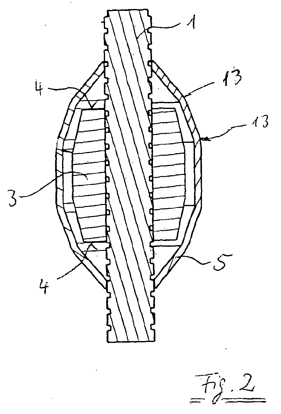
- Schnitt durch den Schlauch mit angesetztem Gewicht gemäß Figur 1;
- Figur 3
- Seitenansicht einer Außenhaut als separates Formteil;
Figur 4- perspektivische Explosionsansicht einer Außenhaut gemäß Figur 3.
- FIG. 1
- the perspective view of a hose section with an attached weight;
- FIG. 2
- Section through the hose with attached weight of Figure 1;
- FIG. 3
- Side view of an outer skin as a separate molding;
- FIG. 4
- perspective exploded view of an outer skin according to FIG. 3.
Figur 1 zeigt in perspektivischer Darstellung einen Abschnitt eines Schlauches 1, an dem ein Rückzugsgewicht 2 angesetzt ist. Der Schlauch 1 ist dabei im hier dargestellten Beispiel als Agraffschlauch ausgebildet. Er kann aber auch als kunststoffummantelter Schlauch ausgebildet sein o.ä.FIG. 1 shows a perspective view of a section of a hose 1, to which a withdrawal weight 2 is attached. The tube 1 is in the Example shown here designed as Agraffschlauch. He can, too be designed as a plastic-coated hose o.ä.
Mit dem Schlauch wird in nicht dargesteller Weise eine Handbrause mit einer Wasserzulaufarmatur für eine Küchenspüle oder ein Handwaschbecken verbunden. Der Schlauch verläuft dabei von seiner Anschlussstelle an der Wasserzulaufarmatur in einer Schlaufe zu einer innen hohlen, rohrförmigen Halterung der Handbrause an der Wasserzulaufarmatur. Über das Rückzugsgewicht wird erreicht, dass der Schlauch nach einem Herausnehmen der Handbrause aus der Halterung bei einem Wiedereinsetzen der Handbrause in die Halterung selbsttätig wieder in die Halterung zurückgleitet.The hose is not dargesteller a hand shower with a Water supply fitting for a kitchen sink or hand basin connected. The hose runs from its connection point to the water inlet fitting in a loop to an inside hollow, tubular holder the hand shower at the water inlet fitting. About the withdrawal weight The hose is reached after removing the hand shower from the holder when replacing the hand shower in the holder automatically slides back into the holder.
Der üblicherweise aus Blei gefertigte Gewichtskörper 3 weist an seinen in Axialrichtung
des Schlauches liegenden Enden Flächen 4 auf, die sich im wesentlichen
normal zur Axialrichtung des Schlauches 1 erstrecken und mit denen
dieser Gewichtskörper 3 auf Kanten aufsitzen kann, an denen der Schlauch 1
beim Zurückgleiten in seine Schlaufenposition in einem Beckenunterschrank
vorbeiläuft. Um dies zu vermeiden, weist das hier dargestellte Rückzugsgewicht
2 eine als separates Formteil 5 ausgebildete Außenhaut auf. Diese hat
parallel zur
Axialrichtung des Schlauches 1 einen stufenfreien Verlauf, da einzelne an ihr
vorhandene Kanten 13 sowohl stumpfe Winkel aufweisen als auch zusätzlich
abgerundet sind.The usually made of lead weight body 3 has at its lying in the axial direction of the
Axial direction of the tube 1 a stepless progression, since individual present at their
Wie dabei in der Figur 2 zu erkennen ist, überragt das Formteil 5 den Gewichtskörper
3 an seinen in Axialrichtung des Schlauches 1 liegenden Enden,
womit die in Normalrichtung dieser Axialrichtung liegenden Flächen 4 in der
gewünschten Weise abzudecken sind.As can be seen in FIG. 2, the molded part 5 projects beyond the weight body
3 at its ends lying in the axial direction of the hose 1,
whereby the lying in the normal direction of this
Des weiteren ist der Figur 2 zu entnehmen, dass zwischen dem Gewichtskörper 3 und der Innenseite des Formteiles 5 ein radialer Abstand vorhanden ist. Bei Anschlag des Rückzugsgewichtes 2 an ein Hindernis wird somit über den Schlauch 1 und dessen Eigenelastizität eine gewisse Dämpfung dieses Anschlages erreicht. Insbesondere kann so ein akustisch hartes Anschlagen vermieden werden. Furthermore, it can be seen from FIG. 2 that between the weight body 3 and the inside of the molding 5, a radial distance is present. When stop the return weight 2 to an obstacle is thus on the Hose 1 and its inherent elasticity a certain damping of this stop reached. In particular, such an acoustically hard striking avoided become.
Wie in der Figur 4 zu erkennen ist, besteht das Formteil 5 aus zwei Halbschalen
6 und 7. Dabei ist insbesondere die Halbschale 6 im hier dargestellten Beispiel
mit zwei Rasthaken 8 versehen. Diese Rasthaken weisen Anlaufschrägen
9 auf, über die sie etwas nach innen gebogen werden, wenn die Halbschale 6
gegen die gegenüberliegende Halbschale 7 gedrückt wird, so dass dann die
Rasthaken 8 in entsprechenden Aufnahmen 10 an der Halbschale 7 einrasten.
Über sich an den Halbschalen 6 und 7 entsprechend gegenüberliegende Führungsstifte
11 und Führungsbuchsen 12 wird dabei ein passgenaues Aufeinandersetzen
der beiden Halbschalen 6, 7 gewährleistet.As can be seen in FIG. 4, the molded part 5 consists of two half-
Diese beiden Halbschalen 6 und 7 können auch bei bereits in Benutzung befindlichen
Schläuchen über den dort vorhandenen Gewichtskörper geclipst werden,
um so den gewünschten Effekt zu erzielen, ein Aufsitzen des Gewichtskörpers
3 zu verhindern, wenn der von ihm umgriffene Schlauch in eine ursprüngliche
Position innerhalb eines Beckenunterschrankes zurückgezogen
wird.These two
Claims (6)
dadurch gekennzeichnet, dass das Gewicht (3) eine Außenhaut (5) aufweist, die parallel zur Axialrichtung des Schlauches (1) einen im wesentlichen stufenfreien Verlauf hat.Hose for connecting a hand shower to a water inlet fitting with a weight (3) attached to the outside of the hose (1),
characterized in that the weight (3) has an outer skin (5) which has a substantially step-free course parallel to the axial direction of the hose (1).
dadurch gekennzeichnet, dass die Außenhaut als separates Formteil (5) das Gewicht (3) umschließt.Hose according to claim 1,
characterized in that the outer skin as a separate molded part (5) surrounds the weight (3).
dadurch gekennzeichnet, dass das Formteil (5) das Gewicht (3) in Axialrichtung des Schlauches (1) überragt.Hose according to claim 1,
characterized in that the molded part (5) projects beyond the weight (3) in the axial direction of the hose (1).
dadurch gekennzeichnet, dass das Formteil aus Kunststoff gebildet ist.Hose according to claim 2,
characterized in that the molded part is formed from plastic.
dadurch gekennzeichnet, dass das Formteil (5) aus wenigstens zwei zusammenclipsbaren Teilen (6, 7) besteht. Hose according to claim 2,
characterized in that the molded part (5) consists of at least two parts which can be clipped together (6, 7).
dadurch gekennzeichnet, dass die Teile über wenigstens ein Filmscharnier verbunden sind.Hose according to claim 5,
characterized in that the parts are connected via at least one film hinge.
Applications Claiming Priority (2)
| Application Number | Priority Date | Filing Date | Title |
|---|---|---|---|
| DE20318373U DE20318373U1 (en) | 2003-11-25 | 2003-11-25 | Connection hose for the hand shower of a kitchen sink |
| DE20318373U | 2003-11-25 |
Publications (2)
| Publication Number | Publication Date |
|---|---|
| EP1536072A2 true EP1536072A2 (en) | 2005-06-01 |
| EP1536072A3 EP1536072A3 (en) | 2006-08-09 |
Family
ID=31970072
Family Applications (1)
| Application Number | Title | Priority Date | Filing Date |
|---|---|---|---|
| EP04024341A Withdrawn EP1536072A3 (en) | 2003-11-25 | 2004-10-13 | Shower hose connection for a hand-held shower in a kitchen sink |
Country Status (2)
| Country | Link |
|---|---|
| EP (1) | EP1536072A3 (en) |
| DE (1) | DE20318373U1 (en) |
Cited By (1)
| Publication number | Priority date | Publication date | Assignee | Title |
|---|---|---|---|---|
| CN104110054A (en) * | 2014-07-04 | 2014-10-22 | 徐军伙 | Conveniently adjusted and mounted balance weight hammer component |
Families Citing this family (1)
| Publication number | Priority date | Publication date | Assignee | Title |
|---|---|---|---|---|
| CN105782562B (en) * | 2016-05-13 | 2018-11-23 | 厦门构简单工贸有限公司 | A kind of draw type tap clump weight |
Family Cites Families (3)
| Publication number | Priority date | Publication date | Assignee | Title |
|---|---|---|---|---|
| US5771934A (en) * | 1994-05-24 | 1998-06-30 | Iw Industries, Inc. | Zinc-based spray faucet hose collar weight |
| US6250338B1 (en) * | 2000-02-29 | 2001-06-26 | Moen Incorporated | Composite faucet hose weight |
| US6460570B1 (en) * | 2001-05-10 | 2002-10-08 | Masco Corporation | Spray faucet hose weight |
-
2003
- 2003-11-25 DE DE20318373U patent/DE20318373U1/en not_active Expired - Lifetime
-
2004
- 2004-10-13 EP EP04024341A patent/EP1536072A3/en not_active Withdrawn
Cited By (2)
| Publication number | Priority date | Publication date | Assignee | Title |
|---|---|---|---|---|
| CN104110054A (en) * | 2014-07-04 | 2014-10-22 | 徐军伙 | Conveniently adjusted and mounted balance weight hammer component |
| CN104110054B (en) * | 2014-07-04 | 2015-07-15 | 徐军伙 | Conveniently adjusted and mounted balance weight hammer component |
Also Published As
| Publication number | Publication date |
|---|---|
| DE20318373U1 (en) | 2004-02-26 |
| EP1536072A3 (en) | 2006-08-09 |
Similar Documents
| Publication | Publication Date | Title |
|---|---|---|
| EP3031370B1 (en) | Insert for a rinsing basin | |
| EP1536072A2 (en) | Shower hose connection for a hand-held shower in a kitchen sink | |
| DE202019000946U1 (en) | Tap water outlet | |
| EP0182308B1 (en) | Safety rail system | |
| DE60306323T2 (en) | Shock safety gear | |
| EP3351698B1 (en) | Drain armature | |
| EP4221553B1 (en) | Device for supporting appliances of daily use | |
| EP3647503A1 (en) | Extraction hose device with a retraction unit | |
| DE3434735A1 (en) | Flexible tube for sanitary fittings having a removable gripping piece and sanitary fitting | |
| DE10358013A1 (en) | Washing machine door locking latch has housing including door state plunger exposing latch when depressed by closing door | |
| DE102017205726A1 (en) | Cutlery basket and household dishwasher | |
| DE102018200530B4 (en) | Fluid line insert | |
| DE202019005705U1 (en) | Shower tray | |
| DE10056858B4 (en) | Mobile emergency or replacement toilet | |
| EP2553306B1 (en) | Flexible water hose | |
| DE3109890C2 (en) | ||
| DE20312478U1 (en) | water fitting | |
| DE202008015549U1 (en) | Construction of a multiply foldable umbrella scaffolding | |
| DE8507614U1 (en) | Sanitary drainage device | |
| DE102024112974A1 (en) | Mobile urination aid and urination system | |
| DE102019115205A1 (en) | Shower tray | |
| DE202011050990U1 (en) | Bathroom furniture for a steam shower and set of a steam device and a bathing furniture | |
| DE102015104930A1 (en) | Toilet attachment for a seat toilet with an integrated urinal | |
| DE8427875U1 (en) | Hose with sanitary fitting | |
| DE102021118430A1 (en) | Retaining device especially for water drainage from flat roofs |
Legal Events
| Date | Code | Title | Description |
|---|---|---|---|
| PUAI | Public reference made under article 153(3) epc to a published international application that has entered the european phase |
Free format text: ORIGINAL CODE: 0009012 |
|
| AK | Designated contracting states |
Kind code of ref document: A2 Designated state(s): AT BE BG CH CY CZ DE DK EE ES FI FR GB GR HU IE IT LI LU MC NL PL PT RO SE SI SK TR |
|
| AX | Request for extension of the european patent |
Extension state: AL HR LT LV MK |
|
| PUAL | Search report despatched |
Free format text: ORIGINAL CODE: 0009013 |
|
| AK | Designated contracting states |
Kind code of ref document: A3 Designated state(s): AT BE BG CH CY CZ DE DK EE ES FI FR GB GR HU IE IT LI LU MC NL PL PT RO SE SI SK TR |
|
| AX | Request for extension of the european patent |
Extension state: AL HR LT LV MK |
|
| RAP1 | Party data changed (applicant data changed or rights of an application transferred) |
Owner name: NIRO-PLAN AG |
|
| 17P | Request for examination filed |
Effective date: 20060930 |
|
| AKX | Designation fees paid |
Designated state(s): AT BE BG CH CY CZ DE DK EE ES FI FR GB GR HU IE IT LI LU MC NL PL PT RO SE SI SK TR |
|
| 17Q | First examination report despatched |
Effective date: 20071122 |
|
| STAA | Information on the status of an ep patent application or granted ep patent |
Free format text: STATUS: THE APPLICATION IS DEEMED TO BE WITHDRAWN |
|
| 18D | Application deemed to be withdrawn |
Effective date: 20080403 |