EP1536070A1 - Vorrichtung zum Eintreiben von Pfählen und Pfahl zur Verwendung mit solch einer Vorrichtung - Google Patents
Vorrichtung zum Eintreiben von Pfählen und Pfahl zur Verwendung mit solch einer Vorrichtung Download PDFInfo
- Publication number
- EP1536070A1 EP1536070A1 EP04292041A EP04292041A EP1536070A1 EP 1536070 A1 EP1536070 A1 EP 1536070A1 EP 04292041 A EP04292041 A EP 04292041A EP 04292041 A EP04292041 A EP 04292041A EP 1536070 A1 EP1536070 A1 EP 1536070A1
- Authority
- EP
- European Patent Office
- Prior art keywords
- mast
- mandrel
- cone
- post
- jaws
- Prior art date
- Legal status (The legal status is an assumption and is not a legal conclusion. Google has not performed a legal analysis and makes no representation as to the accuracy of the status listed.)
- Withdrawn
Links
- 230000033001 locomotion Effects 0.000 claims description 20
- 230000008878 coupling Effects 0.000 claims description 5
- 238000010168 coupling process Methods 0.000 claims description 5
- 238000005859 coupling reaction Methods 0.000 claims description 5
- 239000002184 metal Substances 0.000 claims description 5
- XLYOFNOQVPJJNP-UHFFFAOYSA-N water Substances O XLYOFNOQVPJJNP-UHFFFAOYSA-N 0.000 claims description 3
- 230000003014 reinforcing effect Effects 0.000 claims description 2
- 230000011664 signaling Effects 0.000 claims description 2
- 238000006073 displacement reaction Methods 0.000 abstract 1
- KWGRBVOPPLSCSI-WPRPVWTQSA-N (-)-ephedrine Chemical compound CN[C@@H](C)[C@H](O)C1=CC=CC=C1 KWGRBVOPPLSCSI-WPRPVWTQSA-N 0.000 description 10
- 239000002689 soil Substances 0.000 description 8
- 208000031968 Cadaver Diseases 0.000 description 4
- 238000010276 construction Methods 0.000 description 3
- 238000005553 drilling Methods 0.000 description 3
- 241000196324 Embryophyta Species 0.000 description 2
- 230000000694 effects Effects 0.000 description 2
- 238000009434 installation Methods 0.000 description 2
- 210000002414 leg Anatomy 0.000 description 2
- 210000000056 organ Anatomy 0.000 description 2
- 240000008042 Zea mays Species 0.000 description 1
- 230000004308 accommodation Effects 0.000 description 1
- 230000006978 adaptation Effects 0.000 description 1
- 238000009412 basement excavation Methods 0.000 description 1
- 210000000078 claw Anatomy 0.000 description 1
- 230000000295 complement effect Effects 0.000 description 1
- 230000006835 compression Effects 0.000 description 1
- 238000007906 compression Methods 0.000 description 1
- 230000000994 depressogenic effect Effects 0.000 description 1
- 239000006185 dispersion Substances 0.000 description 1
- 210000003414 extremity Anatomy 0.000 description 1
- 230000001788 irregular Effects 0.000 description 1
- 229930014626 natural product Natural products 0.000 description 1
- 238000005192 partition Methods 0.000 description 1
- 210000004417 patella Anatomy 0.000 description 1
- 230000000630 rising effect Effects 0.000 description 1
- 239000011435 rock Substances 0.000 description 1
- 238000005096 rolling process Methods 0.000 description 1
- 238000000926 separation method Methods 0.000 description 1
- 238000004513 sizing Methods 0.000 description 1
- 238000003971 tillage Methods 0.000 description 1
- 239000002023 wood Substances 0.000 description 1
Images


Classifications
-
- E—FIXED CONSTRUCTIONS
- E04—BUILDING
- E04H—BUILDINGS OR LIKE STRUCTURES FOR PARTICULAR PURPOSES; SWIMMING OR SPLASH BATHS OR POOLS; MASTS; FENCING; TENTS OR CANOPIES, IN GENERAL
- E04H17/00—Fencing, e.g. fences, enclosures, corrals
- E04H17/14—Fences constructed of rigid elements, e.g. with additional wire fillings or with posts
- E04H17/1413—Post-and-rail fences, e.g. without vertical cross-members
- E04H17/1447—Details of connections between rails and posts
- E04H17/1452—Details of connections between rails and posts the ends of the rails are fixed on the lateral sides of the posts
-
- E—FIXED CONSTRUCTIONS
- E04—BUILDING
- E04H—BUILDINGS OR LIKE STRUCTURES FOR PARTICULAR PURPOSES; SWIMMING OR SPLASH BATHS OR POOLS; MASTS; FENCING; TENTS OR CANOPIES, IN GENERAL
- E04H17/00—Fencing, e.g. fences, enclosures, corrals
- E04H17/14—Fences constructed of rigid elements, e.g. with additional wire fillings or with posts
- E04H17/1413—Post-and-rail fences, e.g. without vertical cross-members
- E04H17/1447—Details of connections between rails and posts
- E04H17/1473—Details of connections between rails and posts using fixing devices encircling, partially or fully, the post
Definitions
- the present invention relates to planting equipment of posts, intended to be installed on a transport vehicle such than a tractor.
- the invention further relates to poles usable with such equipment as well as fences or feasible installations with such equipment and poles.
- the present invention aims to achieve equipment planting of poles of simple and effective design.
- the invention particular aim of developing a feasible fence system with this equipment.
- This equipment makes it possible to plant oriented poles of accurately regardless of the inclination of the ground. This orientation can be vertical as is often the case. But it is also possible to carry out work along a different axis. This line of work can be set automatically or by the operator.
- This equipment offers a great flexibility of use because of the simplicity and robustness of its structure.
- This structure simple allows the equipment to be used in difficult conditions, example in areas of difficult access. Because of this simplicity, the equipment is very easily controllable and the driver of the equipment can work precisely so as to position the location of the work, ie the tool at the precise location that to control the evolution of work. The positioning of the tool is done precise way even in irregular terrain since the driver can not only to orient the mast but also once the vehicle stopped near the work site, move the tool holder by the moving frame transversely.
- the equipment may be mounted on a vehicle such as a tractor, in particular an agricultural tractor, on its coupling in three points, either at the front or at the back. It is however preferable for make the work easier that the tool is perfectly visible from driving position and that the vehicle equipped with the equipment is a vehicle particular, either wheeled or chain.
- This equipment can also be installed on a platform rotation carried by the vehicle and in this case the flexibility of use is even greater because the driver will not only have the translation of the mobile frame relative to the mast to position the tool but it can also combine this possibility with a pivoting.
- the mast may consist of a single piece telescopic for some applications, it is interesting to have a greater working height than that offered by a single mast whose height is necessarily reduced to comply with the regulations or to facilitate the movement of the vehicle on not necessarily cleared at the top, so it is interesting that the mast is a telescopic mast.
- This realization of the frame is particularly simple and robust since it is limited to the functional elements. This robustness also makes it possible to effectively absorb the forces transmitted by the tool to the tool holder.
- the toolholder comprises an engine hydraulic axis rotation parallel to the axis of movement of the sled along the mast.
- This hydraulic motor is powered by the hydraulic system of the vehicle.
- This chuck can receive various accessories to make such as a drill bit for drilling rock or concrete but especially a pole.
- the chuck is advantageously equipped hydraulic cylinder integrated in the clamping cone and chuck body to tighten the chuck, its opening being provided by springs of recall.
- the interchangeability of the jaws is very simple since the jaws are controlled by translation of the clamping cone working by ramp effect cooperating with the back of the jaws.
- This back, frustoconical shape is adapted to the shape of the clamping cone.
- the restraint between the cone clamping and jaws is ensured easily by magnetic attraction. This magnetic attraction exercising mainly in the direction perpendicular to the contact surface between the clamping cone and the body chuck but not in a perpendicular direction, does not interfere with translation movement or sliding of the cone on the back jaws.
- the invention also relates to a fence post or signage that can be planted using equipment according to the invention.
- This post is characterized in that it comprises a tip formed of a cone with a screw thread to be screwed into the ground. It is particularly advantageous to terminate the cone with a perforation tip to increase its resistance when screwed into the ground.
- the pole according to the invention has the advantage, on the one hand, of planting easily in the soil, especially with equipment equipped with a mandrel like the one mentioned above. This implementation is done precisely. As the post is screwed, its sinking into the soil does not alter the surrounding soil structure as is the case for a beaten post, the soil being simply compacted by the repression the volume of land occupied by the tip of the pole. The post is also independent of the quality of the tip as is the case of wooden poles whose tip is cut.
- the rotational movement also has the advantage of spreading obstacles and not to blunt or warp the tip like this is the case of a wooden pole which, encountering a particular obstacle hard, sees its point crushed, broken or deviated, which complicates its precise sink.
- the cone is a metal piece provided with a screw thread made of sheet metal.
- This cone is reported at the end of a post, including a wooden post.
- the post may be slightly cut at its end to fit in the cone in which it is held by screws or other fastening means.
- the interior of the cone may also have claws to improve the snap between the cone and the post and transmit effectively the screwing forces exerted by the mandrel on the pole towards the cone.
- This post can also be disassembled, that is to say from the ground or from the ground using equipment equipped with a mandrel.
- the mandrel can turn the post in the direction unscrewing both to take it off the ground and to unscrew it. Then, the post may be torn off by the lift of the carriage or by unscrewing.
- the limited stroke of the chuck jaws is advantageously adapted to the diameter of the pole in a diameter range.
- the invention also relates to a feasible fence system with poles, crossbars and struts.
- This system includes assembly parts. Following a advantageous characteristic, preformed assembly parts composed each of at least two branches having at least partially the section of the fence elements to be assembled (post, crossbeam, strut) to receive an element in each branch.
- the posts thus positioned in a precise way will constitute the fence, which will no longer require adaptation of the sleepers since the interval between the poles will be precise.
- the assembly poles and crossbeams or struts will be easy and fast to realize thanks to these parts of assembly.
- the assembly part is composed of of a tubular element whose section substantially corresponds to that of post to receive this post, and at least one perpendicular side branch to the tubular element, this branch being in the form of a half-cylinder circular section substantially corresponding to the section of the crosses.
- the section of the lateral branch extends tangentially beyond the section in a semicircle to form a drop of water.
- the element tubular carries at least one inclined lateral endpiece with a covering open section, to receive a leg of strength.
- branches are equipped holes for screwing or nailing fence elements.
- the invention relates to a device tillage for excavation or planting work.
- This equipment is intended to be installed on a transport vehicle for example on the three-point hitch of a tractor or preferably on a vehicle designed for this purpose so that the driver can see the equipment for the execution of the works.
- This equipment is equipped with a tool holder for a tool drilling such as a drill or auger to make holes in the soil and extract the load.
- a tool drilling such as a drill or auger
- the axis of the drilling / hole is vertical but it can also be inclined; the rotary tool rotates about this axis along which he must also perform a translational motion for to sink and to extract the earth.
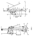
- the equipment consists of a mast 1 carried by a base 2 connected to the vehicle not shown.
- the mast 1 tilting door carries a carriage 3 provided with a rotary tool holder 4 whose axis of ZZ rotation is parallel to the axis of movement of the carriage 3 along the mast 1.
- the carriage 3 is formed of a sled 31 movable along the mast and of a frame 32 with a frame 33 movable transversely to the movement of the sled 31.
- the various angle settings of the mast 1 and translation of the frame 33 make it possible to place the axis of the tool (or the axis of the tool holder ZZ) according to the work to be performed, the carriage 3 moving on the mast according to the progress of the work.
- the telescopic mast 1, carried by the base 2 installed on the vehicle not shown, is formed of a fixed lower portion 11 and a top part 12 deployable.
- the lower part 11 is completed by a double clevis 11-1 which overlaps a cross member 21 of the base 2 while being connected thereto by an axis 22.
- the orientation movement of the mast 1 is preferably controlled by a single joystick, mobile around a kneecap and control the combined movement of the three cylinders for the orientation of the mast, another joystick controls the extension or retraction movement of the mast.
- the adjustment of the orientation of the mast can also be done automatically by servoing on a direction of instruction especially the vertical direction.
- the different means driving the cylinders mast adjustment can be controlled by a microprocessor.
- the mast 1 pivots around the axis XX relative at the base 2, and with the base 2, around the axis YY relative to the vehicle, the carriage 3 moving along the axis ZZ, along the mast 1.
- the carriage 3 is movable along the mast 1 in particular along of its extensible portion 12 via its slider 31 sliding / rolling on the mast by being restrained by cables passing over a pulley 14 at the top end of the mast 1.
- the other end of the cables is connected to an unrepresented jack housed inside the mast and whose the extension / retraction controls the lowering / raising of the sling 31 that is to say, the carriage 3.
- the sled 31 comprises guiding means 31-1 on the mast and it is provided with receiving members 31-2, 31-3 receiving the frame 32 by its fasteners 32-2; 32-3.
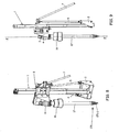
- Figure 3 shows a front view of the equipment of which the base 2 is horizontal and the mast 1 vertical.
- Figure 4 shows a situation analogous except that the vehicle is in a slope and so the base 2 is inclined. In this case we control the tilt cylinders to put the mast 1 in the vertical position or give it the desired inclination.
- the base 2 carrying the mast 1 is formed of a main cross member 21 on which is articulated the mast 1, two triangular flanges 23 at the end of cross-member 21 and a cross-member 24 bearing the bearings 25, 26 for the lateral cylinders 5, 6.
- the base 2 comprises two coupling members 27, 28 for the vehicle. These bodies are formed by the base of the flanges 23 and a respective tab 27-1, 28-1, connected to the cross member, carrying two aligned axes 27-2, 28-2 on the YY direction allowing the pivoting movement referred to above around the YY axis.
- the main cross member 21 is provided with a bearing orifice 22 for the passage of the axis provided at the lower end of the mast 1.
- the axis XX of this orifice 22 is situated in the longitudinal plane of the equipment and consequently that of the vehicle while the two axes of connection and articulation 27-2, 28-2 of the base 2 in the vehicle bearings are transversely oriented (YY) according to the orientation convention chosen here.
- the flanges 23 of the base connected at the top by the upper crossbar 24 are reinforced by two side gussets 29 connecting the main cross member 21 to the flanges 23 and the lower cross member 21 to form a rigid frame.
- the upper crossbar 24 comprises each end a bearing formed of two legs and a hinge axis to each receive the lower end of one of the lateral cylinders of tilt adjustment.
- the tab 13 of the mast to which is connected the upper end 5-2, 6-2 of the two lateral cylinders 5, 6 and the crossbar 24 of the base are offset relative to the mast 1 so that the side cylinders 5, 6 do not interfere with the movement of the carriage 3 and the passage from his rear roller 31-1.
- Cylinders 5, 6 and their joints end are preferably located in a plane parallel to the mast 1.
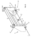
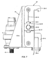
- Figures 6 and 7 show the structure of the carriage 3 without the 31.
- the trolley 3 consists of a trolley provided with receiving means for receiving the frame 32.
- the frame 32 has two upper hooks 32-2 and two hooks lower 32-3.
- the upper brackets 31-1 simply come engage over the upper edge 31-2 of the sling 31 and the two lower hooks 32-3, cover a bar or lower tab 31-1 of the 31.
- the locking of the chassis 32 to the sling 31 is done by a pin 32-4 blocked by a pin in each of the lower hooks 32-3.
- the frame 32 has two lateral supports 32-5, 32-6 carrying the fasteners 32-2, 32-3. These two lateral supports are connected by two 32-7 transverse guide rails and one 32-5 of them carries actuator 32-8 cylinder-shaped parallel to guide rails 32-7.
- the rails receive the movable frame 33.
- the movable frame 33 is connected to the actuator 32-8 to move along the rails, that is to say transversely to the mast 1.
- the vertical movement of the sled 31 combined with the movement transversal mobile frame 33 allows to position exactly the ZZ axis of the motorized tool holder 4.
- the mobile frame 33 comprises a high sleeve 33-3and a bottom sleeve 33-4 connected to the sides 33-1, 33-2 of the frame and sliding on the respective rail 32-7.
- the rails are tubes of round section of the same than the sleeves.
- the bottom 33-5 of the frame is extended forward beyond sleeves 33-3, 33-4 and is connected by gussets 33-6 to the sides 33-1, 33-2 of the frame. This creates a location for the tool holder 4.
- Actuator cylinder 32-8 is connected to one of the supports 32-5 of the chassis 32 by a hinge 32-9 offset to the outside, on the side of the chassis.
- the 32-8 cylinder also crosses the side opposite 33-1 of the frame 33.
- the motorized tool holder 4 equipping the mobile frame 33 is preferably constituted by a hydraulically powered motor controlled by the hydraulic circuit of the vehicle.
- the output shaft 41 of the tool holder 4 is a spline shaft straight on which a coupling sleeve is locked in rotation of complementary shape belonging to the tool.
- Figures 8 to 15 show another embodiment of equipment for planting posts, piles or stakes for panels signaling or the construction of enclosures, fencing and other constructions of this type.
- the equipment comprises, as a tool, a mandrel 16 receiving a post to be planted 17.
- the mandrel 16 is installed on the end of output 41 of the tool holder 4 shaped hydraulic motor.
- the mandrel 16 then receives the upper end of a planting pole 17.
- this tray has an end to plant, pointed and whose tip 171 has a thread 171-1 so as to be able to drive the post in the soil by screwing it.
- the mandrel 16 screws the post in the ground by rotating it while pressing on it with the weight of the assembly formed by the mandrel 16, the toolholder 4 and the carriage 3.
- This post can be wooden or tube metallic.
- the equipment can also be used for the reverse operation that is to say the dismantling of a post without having to dig to dismount it. Just engage the mandrel 16 on the end of the pole, tighten the chuck and rotate it to separate the pole from the ground then draw the post. If it is a screwed post like the one mentioned above, we can unscrew it to extract it.
- the mandrel 16 consists of a body 161 housing the jaws 162 whose inner face 162-1 constitutes clamping surfaces and the outer face 162-2 cooperates with a cone of 163.
- the clamping cone 163 slides relative to the body 161 of the mandrel between an open position and a clamping position.
- the clamping cone 163 cooperates with the jaws 162 by a ramp effect producing their radial movement in the direction of tightening or loosening.
- the jaws 162 are held against the cone of tightening 163 by magnetic studs 162-3 integrated in the outer face 162-2 of the jaws 163.
- the relative sliding of the clamping cone 163 is commanded to the active position by a cylinder integrated in the mandrel, the return to the open position by means of springs 164.
- the jaws 162 are interchangeable and for this the clamping cone 163 can be retracted to clear completely the jaws 162 and allow their exchange.
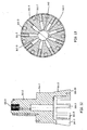
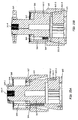
- FIG. 10 shows the detail of mandrel 16 comprising the body 161 formed of two stepped cylindrical parts 161-1, 161-2, the lower part 161-2 forming with the clamping cone 163, the cylinder of the chuck and a guide surface; this function is completed by the upper part 161-1 of the mandrel.
- the lower part 161-2 is continues with guide branches 161-3, radial whose ends 161-3 are connected to a ring 165 so as to form trapezoidal section cavities freely receiving the movable jaws radially.
- the 162 jaws are supported by their active surface 162-1 against the object placed in the mandrel and their bearing surface 162-2 on the outer side, frustoconical cooperates with the clamping cone 163.
- the clamping cone 63 caps the body 161 of the mandrel 16 and slide relative thereto in a clamping position, limited by coming in support either of the jaws against the branches 161-3 or the cone against the outer surface of branches 161-3 depending on the sizing realized in practice.
- the cone 163 With the outer surface of the part 161 of the mandrel, the cone 163 forms a chamber annular cylinder 166 ( Figure 15B) closed at the top by a crown 167.
- the cone 163 itself is provided with a cover 168 carrying guide and return rods 169. These rods 169 traverse the crown 167 and rely on the return springs 164 housed in the body 161.
- the top of the mandrel 16 carries a dispensing head 16A fixed to the body by a cap 16A-1 for the connection of the hydraulic circuit supplying the cylinder (annular chamber) with holes in the body of the mandrel.
- Figure 11 shows an exploded view of the body 161 of the mandrel leaving in the upper part the cylindrical housing than 161-4 with internal splines to get on the fluted exit 41 of the tool holder 4.
- the crown 165 attached to the branches 161-3 of the lower part of the body has radial grooves 165-1 in which the branches 161-3 are locked and the whole is screwed by screws introduced by the bottom of the crown 165.
- This figure also shows one of the jaws 162 with its two housings 162-4 each receiving one magnetic pad 162-3 to attach the jaw to the clamping cone 163 while allowing the clamping cone to slide on the jaw 162 and to push it towards the tightening position or pull it towards the opening.
- Figure 12 is an axial section of the body 161 of the mandrel 16 showing the upper part 161-2, the lower part 161-1 and branches 161-3.
- FIG. 13 is a section of the mandrel at the level of branches 161-3 and jaws 162 showing the arrangement of the jaws.
- These jaws 162 have an elongate trapezoidal section terminated by one end right 162-5 on the inside, extending each bit until clamping surface 162-2 to reach the clamping diameter Dm.
- the partitions formed by the 161-3 branches are radial and thick constant so that the branches and the trapezoidal shape as well as the outer surface of the limbs limit the clamping stroke of jaws 162 so as not to over-tighten or even crush the end of the post placed in the mandrel 16.
- Figure 14 shows four jaw shapes for diameters of pole, different. These jaws 162 have in section the same shape trapezoidal with the same outer surface 162-2 but the radial length LR of the jaws is different depending on the diameter of the pole to be tightened.
- FIGS. 15A, 15B are views in axial section of the mandrel 16, one (15A) showing the mandrel in the change position jaw 162, the taper 163 being completely raised beyond jaws.
- the other figure 15B shows the clamping position.
- the position opening is an intermediate position, the taper 163 styling then at least partially the outer side of the jaws to retain them.
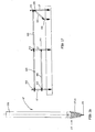
- FIG 16 shows an example of post 17 according to the invention which crashes with the equipment described with the aid of FIGS. at 15B.
- This post 17 or post consists of a body for example wood or a metal tube.
- the lower end ends with a tip conical 171 circular section provided with an outer thread 171-1 next the conical profile and terminated at the bottom, if necessary, by a mouthpiece reinforced 173 like that of a perforation tool.
- the conical tip 171 provided with the fillet 171-1 is preferably a metal piece attached to the end of the body of the pole 17.
- Such posts 17 or piles can be used for multiple applications and in particular to the realization of fences like those presented in Figure 17.
- This fence consists of 17 connected vertical piles by sleepers 100 and at the end or at the corners of the pile is held by a strut 101 itself attached to a short pile 102. These various piles are screwed into the ground.
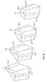
- connection between the posts 17 or the sleepers 100 or the struts 101 is made using assembly parts 211-219 such than those shown in Figures 18 to 26. These assembly parts are consist of one or more branches.
- the assembly part 211 of FIG. 18 is intended for the assembly of a pile 17 and a cross 100.
- the vertical branch is constituted by a tubular element and the other horizontal branch B2 is constituted by a covering element B21 with semicircular section, extended on both sides by a substantially tangent band forming a drop of water B22, B23.
- the section of the tubular element is adapted to that of the fence post so you can get on it.
- the section of the lateral branch is adapted to the cross section.
- the two branches B1, B2 are square.
- the branches are provided with B3 holes to be screwed or studded at the stake and at the cross.
- Figure 19 is a variant 212 of the part of Figure 18 which is distinguished by two lateral branches B2, perpendicular, intended to receive each the end of a cross.
- Figures 20, 21 show other pieces 213, 214 of this type each composed of a branch tubular B1 intended to be fitted on the tray or the pile and two or three branches B2 to the square to serve, in the case of the figure 20, for a corner post with two perpendicular crosspieces and
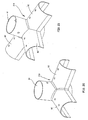
- Figures 22 to 25 show four element examples assembly 215-218 for connecting a post or pile 17 to one or more struts 101.
- the element assembly 215 consists of a tubular branch B 1 intended to receive the post 17 and an inclined branch B3, having a semicircular section B41 extended by gussets B42, B43 to receive the end superior of a strut. These elements are also equipped with B3 holes for screwing.
- Fig. 23 shows a connecting element 216 with two side branches B3 for two struts.
- Fig. 24 shows a link member 217 for a pole corner with two struts 101 placed in perpendicular planes and inclined elements.
- Figure 25 shows an element 218 with three branches B4 for an intermediate post with two branches placed in the same plane and a branch in a perpendicular plane.
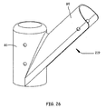
- FIG. 26 shows a link element 219 for connecting a strut 101 to a short pile 102 serving as support for the strut 101, and comprising a sleeve B1 and a rising branch B5 structure similar to that of the previous figures.
Landscapes
- Engineering & Computer Science (AREA)
- Architecture (AREA)
- Civil Engineering (AREA)
- Structural Engineering (AREA)
- Earth Drilling (AREA)
Applications Claiming Priority (2)
| Application Number | Priority Date | Filing Date | Title |
|---|---|---|---|
| FR0312523 | 2003-10-27 | ||
| FR0312523A FR2858988B1 (fr) | 2003-10-27 | 2003-10-27 | Equipement de plantation de poteaux et poteaux utilisables avec un tel equipement |
Publications (1)
| Publication Number | Publication Date |
|---|---|
| EP1536070A1 true EP1536070A1 (de) | 2005-06-01 |
Family
ID=34112878
Family Applications (1)
| Application Number | Title | Priority Date | Filing Date |
|---|---|---|---|
| EP04292041A Withdrawn EP1536070A1 (de) | 2003-10-27 | 2004-08-12 | Vorrichtung zum Eintreiben von Pfählen und Pfahl zur Verwendung mit solch einer Vorrichtung |
Country Status (2)
| Country | Link |
|---|---|
| EP (1) | EP1536070A1 (de) |
| FR (1) | FR2858988B1 (de) |
Cited By (1)
| Publication number | Priority date | Publication date | Assignee | Title |
|---|---|---|---|---|
| CN113090103A (zh) * | 2021-02-20 | 2021-07-09 | 山东齐泰实业集团股份有限公司 | 一种组合式建筑施工防护装置以及组装方法 |
Families Citing this family (1)
| Publication number | Priority date | Publication date | Assignee | Title |
|---|---|---|---|---|
| AU2020290631B2 (en) * | 2019-06-11 | 2026-04-02 | Trigger Engineering & Consulting Pty Ltd | Fence post stay for wire fences |
Citations (9)
| Publication number | Priority date | Publication date | Assignee | Title |
|---|---|---|---|---|
| US1563024A (en) * | 1924-02-01 | 1925-11-24 | Grimaud Gustave | Reenforced-concrete stake |
| US3300988A (en) * | 1960-12-23 | 1967-01-31 | Raymond Int Inc | Apparatus for forming piles |
| GB1125853A (en) * | 1967-01-16 | 1968-09-05 | Marutai Doboku Company Ltd | A pile driving apparatus including earth boring equipment |
| US4239419A (en) * | 1977-10-27 | 1980-12-16 | Gillen William F Jr | Precast concrete threaded pilings |
| JPS61106824A (ja) * | 1984-10-29 | 1986-05-24 | Chuo Jidosha Kogyo Kk | 杭打機の油圧オ−ガ−装置 |
| EP0228138A2 (de) * | 1985-12-31 | 1987-07-08 | Gaspar Jozef Coelus | Verfahren zum Einbringen eines Betonpfahls in den Boden und Hohlbohrschraubpfahl zur Durchführung des Verfahrens |
| CA1338064C (en) * | 1988-12-20 | 1996-02-20 | Alberta Anchors Inc. | Ground anchor installing apparatus |
| US6142453A (en) * | 1998-07-22 | 2000-11-07 | Martin; Matthew | Fence system |
| GB2357782A (en) * | 1999-12-30 | 2001-07-04 | Presco Pressings | Fence panel construction |
-
2003
- 2003-10-27 FR FR0312523A patent/FR2858988B1/fr not_active Expired - Fee Related
-
2004
- 2004-08-12 EP EP04292041A patent/EP1536070A1/de not_active Withdrawn
Patent Citations (9)
| Publication number | Priority date | Publication date | Assignee | Title |
|---|---|---|---|---|
| US1563024A (en) * | 1924-02-01 | 1925-11-24 | Grimaud Gustave | Reenforced-concrete stake |
| US3300988A (en) * | 1960-12-23 | 1967-01-31 | Raymond Int Inc | Apparatus for forming piles |
| GB1125853A (en) * | 1967-01-16 | 1968-09-05 | Marutai Doboku Company Ltd | A pile driving apparatus including earth boring equipment |
| US4239419A (en) * | 1977-10-27 | 1980-12-16 | Gillen William F Jr | Precast concrete threaded pilings |
| JPS61106824A (ja) * | 1984-10-29 | 1986-05-24 | Chuo Jidosha Kogyo Kk | 杭打機の油圧オ−ガ−装置 |
| EP0228138A2 (de) * | 1985-12-31 | 1987-07-08 | Gaspar Jozef Coelus | Verfahren zum Einbringen eines Betonpfahls in den Boden und Hohlbohrschraubpfahl zur Durchführung des Verfahrens |
| CA1338064C (en) * | 1988-12-20 | 1996-02-20 | Alberta Anchors Inc. | Ground anchor installing apparatus |
| US6142453A (en) * | 1998-07-22 | 2000-11-07 | Martin; Matthew | Fence system |
| GB2357782A (en) * | 1999-12-30 | 2001-07-04 | Presco Pressings | Fence panel construction |
Non-Patent Citations (1)
| Title |
|---|
| PATENT ABSTRACTS OF JAPAN vol. 010, no. 291 (M - 522) 3 October 1986 (1986-10-03) * |
Cited By (2)
| Publication number | Priority date | Publication date | Assignee | Title |
|---|---|---|---|---|
| CN113090103A (zh) * | 2021-02-20 | 2021-07-09 | 山东齐泰实业集团股份有限公司 | 一种组合式建筑施工防护装置以及组装方法 |
| CN113090103B (zh) * | 2021-02-20 | 2023-10-27 | 山东齐泰实业集团股份有限公司 | 一种组合式建筑施工防护装置以及组装方法 |
Also Published As
| Publication number | Publication date |
|---|---|
| FR2858988A1 (fr) | 2005-02-25 |
| FR2858988B1 (fr) | 2006-12-08 |
Similar Documents
| Publication | Publication Date | Title |
|---|---|---|
| US20130233625A1 (en) | Powered Auger Support Assembly for a Vehicle | |
| US5836402A (en) | Auger-holder | |
| EP0096622B1 (de) | Verfahren und Vorrichtung zum Erdbohren | |
| EP0505470B1 (de) | Anhänger mit kombinierten mitteln zum kuppeln und zentrieren | |
| FR2858997A1 (fr) | Equipement de travail des sols pour des travaux de forage et de plantation et poteaux utilisables avec un tel equipement | |
| WO2008064200A2 (en) | Tree spade for atv | |
| DE202012012566U1 (de) | Heckträger | |
| EP1536070A1 (de) | Vorrichtung zum Eintreiben von Pfählen und Pfahl zur Verwendung mit solch einer Vorrichtung | |
| EP1607363A2 (de) | Kran mit einem teleskopierbarem Ausleger | |
| FR2561853A1 (fr) | Appareil adaptable a l'arriere des tracteurs pour l'accouplement d'outils agraires ou autres dits " portes trois points ", notamment | |
| EP1827945B1 (de) | Vorrichtung zum anheben und transportieren von lasten | |
| KR101347330B1 (ko) | 트랙터용 써레 | |
| FR2680444A1 (fr) | Taille-haies sur rails. | |
| EP2959759A1 (de) | Landwirtschaftliche maschine, die mit einer zentriervorrichtung ausgestattet ist | |
| FR2612041A1 (fr) | Elevateur associe a une tariere pour tracteur agricole | |
| FR2545432A1 (fr) | Tracteur muni d'un dispositif de changement rapide des roues | |
| FR2612359A1 (fr) | Dispositif d'attelage d'un instrument de travail a un tracteur | |
| FR2683696A1 (fr) | Pulverisateur en v a commande de repliement hydraulique des trains de disques. | |
| CA2478127A1 (fr) | Machine agricole destinee a etre attelee a une barre d'attelage d'un vehicule tracteur | |
| FR2563684A1 (fr) | Machine agricole pour travailler le sol | |
| FR2763782A1 (fr) | Equipement ayant une forme prismatique allongee monte en travers sur une machine agricole et transformable pour son transport en long | |
| AT1031U1 (de) | Erdbohreinrichtung | |
| EP0847683A1 (de) | Grossflächen-Drillmaschine | |
| FR2567092A1 (fr) | Tracto-pelle articule a usage agricole et de travaux publics | |
| CA2564358A1 (fr) | Dispositif de montage d'une lame de bouteur a l'avant ou a l'arriere d'un tracteur |
Legal Events
| Date | Code | Title | Description |
|---|---|---|---|
| PUAI | Public reference made under article 153(3) epc to a published international application that has entered the european phase |
Free format text: ORIGINAL CODE: 0009012 |
|
| AK | Designated contracting states |
Kind code of ref document: A1 Designated state(s): AT BE BG CH CY CZ DE DK EE ES FI FR GB GR HU IE IT LI LU MC NL PL PT RO SE SI SK TR |
|
| AX | Request for extension of the european patent |
Extension state: AL HR LT LV MK |
|
| 17P | Request for examination filed |
Effective date: 20051201 |
|
| AKX | Designation fees paid |
Designated state(s): AT BE BG CH CY CZ DE DK EE ES FI FR GB GR HU IE IT LI LU MC NL PL PT RO SE SI SK TR |
|
| STAA | Information on the status of an ep patent application or granted ep patent |
Free format text: STATUS: THE APPLICATION IS DEEMED TO BE WITHDRAWN |
|
| 18D | Application deemed to be withdrawn |
Effective date: 20090303 |