EP1535712A1 - A method for producing a replication master, replication method and replication master - Google Patents
A method for producing a replication master, replication method and replication master Download PDFInfo
- Publication number
- EP1535712A1 EP1535712A1 EP03354086A EP03354086A EP1535712A1 EP 1535712 A1 EP1535712 A1 EP 1535712A1 EP 03354086 A EP03354086 A EP 03354086A EP 03354086 A EP03354086 A EP 03354086A EP 1535712 A1 EP1535712 A1 EP 1535712A1
- Authority
- EP
- European Patent Office
- Prior art keywords
- master
- layer
- replication
- smoothening
- coating
- Prior art date
- Legal status (The legal status is an assumption and is not a legal conclusion. Google has not performed a legal analysis and makes no representation as to the accuracy of the status listed.)
- Granted
Links
- 230000010076 replication Effects 0.000 title claims abstract description 58
- 238000000034 method Methods 0.000 title claims abstract description 49
- 238000004519 manufacturing process Methods 0.000 title claims abstract description 27
- 239000011248 coating agent Substances 0.000 claims abstract description 17
- 238000000576 coating method Methods 0.000 claims abstract description 17
- 230000003746 surface roughness Effects 0.000 claims abstract description 12
- 239000010410 layer Substances 0.000 claims description 155
- 230000003287 optical effect Effects 0.000 claims description 52
- 239000003292 glue Substances 0.000 claims description 30
- 239000000463 material Substances 0.000 claims description 22
- 239000000758 substrate Substances 0.000 claims description 19
- 239000002904 solvent Substances 0.000 claims description 16
- 229920002120 photoresistant polymer Polymers 0.000 claims description 8
- 229920003229 poly(methyl methacrylate) Polymers 0.000 claims description 8
- 239000004926 polymethyl methacrylate Substances 0.000 claims description 8
- 238000002310 reflectometry Methods 0.000 claims description 8
- 239000002356 single layer Substances 0.000 claims description 8
- 238000012512 characterization method Methods 0.000 claims description 5
- 239000003822 epoxy resin Substances 0.000 claims description 5
- 229920000647 polyepoxide Polymers 0.000 claims description 5
- 239000002861 polymer material Substances 0.000 claims description 5
- 238000001314 profilometry Methods 0.000 claims description 5
- 238000004026 adhesive bonding Methods 0.000 claims description 4
- 238000003618 dip coating Methods 0.000 claims description 4
- 239000007788 liquid Substances 0.000 claims description 4
- 239000002195 soluble material Substances 0.000 claims description 4
- 238000004528 spin coating Methods 0.000 claims description 3
- 230000005540 biological transmission Effects 0.000 claims description 2
- 238000005259 measurement Methods 0.000 claims description 2
- 230000001419 dependent effect Effects 0.000 claims 1
- 238000000151 deposition Methods 0.000 description 23
- 230000008021 deposition Effects 0.000 description 19
- 229920006335 epoxy glue Polymers 0.000 description 9
- 239000010931 gold Substances 0.000 description 8
- 238000007516 diamond turning Methods 0.000 description 7
- PCHJSUWPFVWCPO-UHFFFAOYSA-N gold Chemical compound [Au] PCHJSUWPFVWCPO-UHFFFAOYSA-N 0.000 description 7
- 229910052737 gold Inorganic materials 0.000 description 7
- CSCPPACGZOOCGX-UHFFFAOYSA-N Acetone Chemical compound CC(C)=O CSCPPACGZOOCGX-UHFFFAOYSA-N 0.000 description 6
- 238000005498 polishing Methods 0.000 description 6
- 238000012546 transfer Methods 0.000 description 4
- 239000007769 metal material Substances 0.000 description 3
- 230000004323 axial length Effects 0.000 description 2
- 238000001816 cooling Methods 0.000 description 2
- 238000011161 development Methods 0.000 description 2
- 230000018109 developmental process Effects 0.000 description 2
- 229910003460 diamond Inorganic materials 0.000 description 2
- 239000010432 diamond Substances 0.000 description 2
- 239000002184 metal Substances 0.000 description 2
- 229910052751 metal Inorganic materials 0.000 description 2
- 238000001451 molecular beam epitaxy Methods 0.000 description 2
- 230000005855 radiation Effects 0.000 description 2
- 238000011160 research Methods 0.000 description 2
- 238000007493 shaping process Methods 0.000 description 2
- 238000004381 surface treatment Methods 0.000 description 2
- 238000002424 x-ray crystallography Methods 0.000 description 2
- 239000004593 Epoxy Substances 0.000 description 1
- 238000002441 X-ray diffraction Methods 0.000 description 1
- 238000010521 absorption reaction Methods 0.000 description 1
- 238000004458 analytical method Methods 0.000 description 1
- 238000005229 chemical vapour deposition Methods 0.000 description 1
- 238000007598 dipping method Methods 0.000 description 1
- 230000000694 effects Effects 0.000 description 1
- 238000005516 engineering process Methods 0.000 description 1
- 230000009969 flowable effect Effects 0.000 description 1
- 239000011521 glass Substances 0.000 description 1
- 238000001659 ion-beam spectroscopy Methods 0.000 description 1
- 230000001788 irregular Effects 0.000 description 1
- 238000003754 machining Methods 0.000 description 1
- 238000001755 magnetron sputter deposition Methods 0.000 description 1
- 230000010070 molecular adhesion Effects 0.000 description 1
- 238000002139 neutron reflectometry Methods 0.000 description 1
- 238000001956 neutron scattering Methods 0.000 description 1
- 238000005240 physical vapour deposition Methods 0.000 description 1
- BASFCYQUMIYNBI-UHFFFAOYSA-N platinum Chemical compound [Pt] BASFCYQUMIYNBI-UHFFFAOYSA-N 0.000 description 1
- 229920000642 polymer Polymers 0.000 description 1
- 238000000926 separation method Methods 0.000 description 1
- 239000000126 substance Substances 0.000 description 1
- 230000005469 synchrotron radiation Effects 0.000 description 1
- 238000007669 thermal treatment Methods 0.000 description 1
Images


Classifications
-
- B—PERFORMING OPERATIONS; TRANSPORTING
- B29—WORKING OF PLASTICS; WORKING OF SUBSTANCES IN A PLASTIC STATE IN GENERAL
- B29C—SHAPING OR JOINING OF PLASTICS; SHAPING OF MATERIAL IN A PLASTIC STATE, NOT OTHERWISE PROVIDED FOR; AFTER-TREATMENT OF THE SHAPED PRODUCTS, e.g. REPAIRING
- B29C33/00—Moulds or cores; Details thereof or accessories therefor
- B29C33/56—Coatings, e.g. enameled or galvanised; Releasing, lubricating or separating agents
-
- B—PERFORMING OPERATIONS; TRANSPORTING
- B29—WORKING OF PLASTICS; WORKING OF SUBSTANCES IN A PLASTIC STATE IN GENERAL
- B29C—SHAPING OR JOINING OF PLASTICS; SHAPING OF MATERIAL IN A PLASTIC STATE, NOT OTHERWISE PROVIDED FOR; AFTER-TREATMENT OF THE SHAPED PRODUCTS, e.g. REPAIRING
- B29C33/00—Moulds or cores; Details thereof or accessories therefor
- B29C33/38—Moulds or cores; Details thereof or accessories therefor characterised by the material or the manufacturing process
- B29C33/3842—Manufacturing moulds, e.g. shaping the mould surface by machining
- B29C33/3857—Manufacturing moulds, e.g. shaping the mould surface by machining by making impressions of one or more parts of models, e.g. shaped articles and including possible subsequent assembly of the parts
- B29C33/3878—Manufacturing moulds, e.g. shaping the mould surface by machining by making impressions of one or more parts of models, e.g. shaped articles and including possible subsequent assembly of the parts used as masters for making successive impressions
-
- B—PERFORMING OPERATIONS; TRANSPORTING
- B29—WORKING OF PLASTICS; WORKING OF SUBSTANCES IN A PLASTIC STATE IN GENERAL
- B29C—SHAPING OR JOINING OF PLASTICS; SHAPING OF MATERIAL IN A PLASTIC STATE, NOT OTHERWISE PROVIDED FOR; AFTER-TREATMENT OF THE SHAPED PRODUCTS, e.g. REPAIRING
- B29C39/00—Shaping by casting, i.e. introducing the moulding material into a mould or between confining surfaces without significant moulding pressure; Apparatus therefor
- B29C39/02—Shaping by casting, i.e. introducing the moulding material into a mould or between confining surfaces without significant moulding pressure; Apparatus therefor for making articles of definite length, i.e. discrete articles
- B29C39/12—Making multilayered or multicoloured articles
- B29C39/123—Making multilayered articles
- B29C39/126—Making multilayered articles by casting between two preformed layers, e.g. deformable layers
-
- B—PERFORMING OPERATIONS; TRANSPORTING
- B29—WORKING OF PLASTICS; WORKING OF SUBSTANCES IN A PLASTIC STATE IN GENERAL
- B29C—SHAPING OR JOINING OF PLASTICS; SHAPING OF MATERIAL IN A PLASTIC STATE, NOT OTHERWISE PROVIDED FOR; AFTER-TREATMENT OF THE SHAPED PRODUCTS, e.g. REPAIRING
- B29C33/00—Moulds or cores; Details thereof or accessories therefor
- B29C33/56—Coatings, e.g. enameled or galvanised; Releasing, lubricating or separating agents
- B29C33/58—Applying the releasing agents
-
- B—PERFORMING OPERATIONS; TRANSPORTING
- B29—WORKING OF PLASTICS; WORKING OF SUBSTANCES IN A PLASTIC STATE IN GENERAL
- B29C—SHAPING OR JOINING OF PLASTICS; SHAPING OF MATERIAL IN A PLASTIC STATE, NOT OTHERWISE PROVIDED FOR; AFTER-TREATMENT OF THE SHAPED PRODUCTS, e.g. REPAIRING
- B29C33/00—Moulds or cores; Details thereof or accessories therefor
- B29C33/56—Coatings, e.g. enameled or galvanised; Releasing, lubricating or separating agents
- B29C33/60—Releasing, lubricating or separating agents
- B29C33/62—Releasing, lubricating or separating agents based on polymers or oligomers
-
- B—PERFORMING OPERATIONS; TRANSPORTING
- B29—WORKING OF PLASTICS; WORKING OF SUBSTANCES IN A PLASTIC STATE IN GENERAL
- B29K—INDEXING SCHEME ASSOCIATED WITH SUBCLASSES B29B, B29C OR B29D, RELATING TO MOULDING MATERIALS OR TO MATERIALS FOR MOULDS, REINFORCEMENTS, FILLERS OR PREFORMED PARTS, e.g. INSERTS
- B29K2995/00—Properties of moulding materials, reinforcements, fillers, preformed parts or moulds
- B29K2995/0037—Other properties
- B29K2995/0072—Roughness, e.g. anti-slip
- B29K2995/0073—Roughness, e.g. anti-slip smooth
Definitions
- the present invention relates to a method for producing a replication master having a surface with low roughness, comprising the steps of forming said master such as to have a desired external surface shape which at least partially corresponds to a counterform of a surface of an object to be produced by replication, and treating said external surface of said master to obtain a predetermined surface roughness value.
- Such a method is for example known from document US 4,525,853.
- This document describes the case of a replication master which is to be used for producing an X-ray focussing mirror comprising a plurality of layer pairs for reflecting and simultaneously focussing X-rays.
- the master is made from a metal material resembling a cone, the external surface shape of which corresponds to the curved counterform of the surface of the mirror to be produced by replication.
- This replication process which follows the preliminary production of the replication master essentially comprises coating the master with suitable mirror materials, for example by molecular beam epitaxy (MBE) deposition or other deposition methods well-known in the field of monolayer or multilayer production.
- MBE molecular beam epitaxy
- the master surface on which these layers are grown has to be as smooth as possible in order to grow smooth layers having a low surface and interface roughness which negatively effects the mirrors reflectivity.
- the prior art proposes to treat the master surface by diamond turning.
- diamond turning leads to surfaces which look smooth on a macroscopic scale, but today the optimum roughness obtainable by this method is in the order of 20 Angströms (root mean square, rms) and thus still much too high to deposit monolayers, bilayers or multilayers for optical purposes on such a master like for example for producing X-ray optics and other high performance optics.
- the prior art therefore proposes a second kind of surface treatment to be applied, namely mechanically polishing the diamond turned master surface.
- This mechanical polishing can reduce the roughness of the master surface to values of approximately 5 Angströms or less, so that the master can then successfully be used for the production of optical components by replication.
- this object can be achieved when said method comprises the step of coating at least a part of said master with a smoothening layer.
- This smoothening layer is a layer which due to a certain flowability of its material displays a smaller roughness at its top surface than the surface on which it has been grown, in contrast to for example ordinary metallic monolayers, the surface of which usually displays a larger roughness than the surface of the substrate on which they have been grown.
- a diamond turned master surface having a roughness of approximately 20 Angströms can be coated with such a smoothening layer displaying a roughness of only 5 Angströms or less after the end of the coating step.
- the surface of the smoothening layer then forms the new smooth master surface.
- said smoothening layer is applied by dip-coating or spin-coating a liquid smoothening material on said master and hardening said smoothening material.
- Dip-coating and spin-coating are well-known technologies and will therefore not be described in detail. It should, however, be pointed out that these coating techniques are much less time-consuming to realise than the polishing or superpolishing techniques proposed in the prior art.
- the object to be produced by replication is formed on the smooth master surface and has to be released at the end of the production operation.
- the method according to the invention can therefore comprise the step of coating at least a part of said master with a release layer.
- This release layer is then chemically or mechanically removed when production of the object is terminated, so that contact between the master and the object gets lost and the cone-shaped master can be pulled out of the surrounding object.
- the release layer is deposited on top of the smoothening layer, the master can therefore be recovered with the smoothening layer still being on top of the master surface, so that the smooth master can immediately be re-used for the production of another object in a next replication cycle.
- the release layer between the master core and the smoothening layer. In this case only the core of the master will be recovered, whereas the smoothening layer will stick to the object separated from the master. The smoothening layer may then have to be removed from the object.
- the smoothening layer takes over the role of the release layer thus preventing from the coating of a release layer.
- said smoothening layer and/or said release layer is made of a soluble material, in particular a soluble polymer material, for example a PMMA photoresist.
- a soluble material for example a PMMA photoresist.
- the object can then easily be separated from the master by immersing the master with the object on top in a suitable solvent.
- acetone can be chosen as such a suitable solvent.
- the method for producing a replication master according to the invention leads to a master having an extremely smooth surface, which is formed either by the smoothening layer or the release layer, so that one can then easily continue the method for producing the replication master to a complete replication method for producing a smooth object having a low surface roughness, comprising the steps of producing a replication master by a method according to any of the above-discussed embodiments, coating at least a part of said master with an object material such that the surface of said object corresponds to a counterform of said master, and releasing said object from said master.
- the releasing step can in principle be executed by cooling the master so that it shrinks more than the surrounding object.
- said releasing step comprises dissolving said smoothening layer and/or said release layer on top of said master by a solvent.
- acetone may be chosen as a suitable solvent for example in the case of a smoothening layer and/or a release layer made from a polymer material, for example a PMMA photoresist.
- the releasing step leads to the separation of the master from the object produced by replication.
- optical components to be produced for example reflective multilayer mirrors for X-rays, EUV or IR or synchrotron radiation, laser light or neutrons
- the object may be too thin and fragile to be used as a stand-alone device. It is therefore advisable to transfer the object produced on the master to a kind of substrate before separating it from the master.
- An advantageous improvement of the replication method for producing the smooth object according to the invention therefore comprises the step of providing glue to said object and/or to an object support and glueing them together before executing said releasing step. By doing so the object can be stabily transferred to the object support before executing the releasing step, i.e.
- the releasing step comprises dissolving the smoothening layer and/or the release layer by a solvent
- the amount of glue used in this embodiment can be chosen such as to fill gaps between said object and said object support. This leads to the following advantage provided by the method according to the invention:
- Replication methods used for producing optical devices are usually based on cone-shaped replication masters onto which the optical device, i.e. the object, is grown.
- the object i.e. the object
- the object support usually has to be rather precisely preshaped to have an external shape which more or less corresponds to the counterform of the object. This involves preliminary machining steps during the production of object supports, and in particular different kinds of object support have to be prepared for different kinds of objects to be transferred to these supports, e. g. objects having different sizes.
- said object is an optical device, e.g. a reflection or transmission monolayer, bilayer or multilayer.
- optical device e.g. a reflection or transmission monolayer, bilayer or multilayer.
- Au monolayers, W/Si multilayers, Pt/C multilayers, Mo/Si multilayers etc. as such optical devices, which are commonly used in X-ray, EUV or synchrotron scattering applications, for example macromolecular X-ray crystallography or X-ray diffraction analysis.
- the method according to the invention allows to obtain a smooth master, and the subsequent steps of the replication method for producing the object are in principle well known, exceptional disturbances may occur either during coating the master with the smoothening layer or during the subsequent deposition of the object on the smoothened master surface. Regardless of whether these disturbances are mechanical or chemical in nature, they will negatively affect the surface profile of the object and/or its optical behaviour. It would of course be extremely inefficient to discover e. g. a disturbance due to an irregular smoothening layer only after having released the entire finished object from the master.
- the replication method according to the invention furthermore comprises the step of characterising said optical device on top of said master before executing said releasing step, wherein said characterisation step may e. g.
- profilometry analyses the surface shape of the object
- reflectometry will directly yield information about its optical behaviour.
- Such a characterisation should be made when a multilayer object is finished and it can even be made after the first few layers of the multilayer object have been deposited on the master surface. If during this characterisation important disturbances are observed, one can immediately interrupt the further production of the object, separate the object as it is at that time from the master and start a new replication cycle. In other words, one can e. g. coat the master with a fresh smoothening layer and restart the deposition of the first layers of the multilayer object, thus avoiding unnecessary production steps in order to save time and cost.
- the object material and the material of said glue are identical. In this case it may be completely sufficient to coat the smoothened master with a thick layer of glue and to attach the thus prepared master with the glue layer on top to an object support. After hardening of the glue and removal of the smoothening layer and/or the release layer and subsequent removal of the master, the object support will have an extremely smooth substrate made from hardened glue on top, the external shape of which corresponds to the counterform of the smoothened master surface.
- said object material and said glue comprise epoxy resin.
- This material can be easily applied to the smoothened master surface and/or the support surface in its liquid state, and after hardening it will serve as a stable substrate on which an optical multilayer may be deposited.
- the method may furthermore comprise the step of coating at least a part of said master with a protection layer on top of said smoothening layer or release layer before applying said object material.
- a protection layer on top of said smoothening layer or release layer before applying said object material.
- the protection layer can therefore be used to protect the epoxy resin or other glue during the releasing step and subsequent deposition steps.
- This protection layer may e. g. be a thin metal layer. As it is directly deposited on the smoothening layer or on the extremely smooth release layer, it will also display an extremely low surface roughness on its top surface, so that it also represents a smooth substrate for the further deposition of an optical device after the releasing step.
- the invention furthermore relates to a replication master for producing a smooth object having a low surface roughness, said master having an external surface shape which at least partially corresponds to a counterform of a surface of said object, characterised in that at least a part of said master is coated with a smoothening layer.
- this replication master can be produced by the method according to the invention.
- Such a smoothened replication master can in general be used for any kind of replication production method without any limitation to the field of optical devices or other monolayers, bilayers or multilayers.
- such a replication master according to the invention can at least partially be coated with a release layer in order to facilitate release of a future object produced by replication from the master itself.
- said smoothening layer and/or said release layer is made of a soluble material, in particular a soluble polymer material, for example a PMMA photoresist.
- Figure 1 shows a perspective view of an ideal replication master 10 used for the production of aspherical optical devices, for example monolayers, bilayers or multilayers, which are used as mirrors in X-ray, EUV, synchrotron or neutron scattering research.
- the master 10 is typically made from metal material and is cone-shaped, so that an object, in particular an optical device deposited on the master surface will have the desired curvature for focussing and/or collimating purposes.
- This object support 12 can be a rectangular block of metal or other stable material having a length corresponding to the axial length of the master 10 and being provided with a recess 14 the shape of which corresponds to a counterform of a part of the external surface of the master 10.
- the recess 14 in the object support 12 is approximately shaped such that it can receive half of the master 10 when inserted into recess 14, the other half of the master 10 protruding from the object support 12.
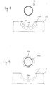
- the idealistic representation of the master 10 having smooth surfaces in figure 1 does not correspond to reality when produced by the shaping processes described above, e.g. diamond turning. Rather the master 10 has to be imagined as having rough surfaces, as is schematically shown in the perspective view of figure 3a and in the front view of the broad end of the cone-shaped master 10 in figure 3b. Even after diamond turning the surface roughness of the master 10 will still be in an order of magnitude of approximately 20 ⁇ . Directly depositing an optical monolayer, bilayer or multilayer on top of such a rough master 10 would yield surface and interface roughness values of the optical layer(s) in at least the same order of magnitude reducing their reflectivity to values which would prevent their use in modern optical devices for research or industrial purposes.
- the rough master 10 is therefore coated with a smoothening layer 16.
- the smoothening layer 16 can for example be applied by dip-coating, i.e. dipping the master 10 into a tank containing the smoothening layer material, removing the master 10 from the tank and, if necessary, curing the thin layer 16 which adheres to the master surface, for example by special thermal treatments well-known in the art. After this hardening process the surface of the smoothening layer 16 has a much smaller roughness as the master surface on which it has been grown. The hardened and smooth surface of the smoothening layer 16 therefore forms an ideal basis for the deposition of an optical monolayer, bilayer or multilayer.
- a liquid and curable polymer in particular a PMMA photoresist can be chosen.
- FIGs 5a and 5b schematically show the result of the next step of the replication method according to an embodiment of the invention.
- the master 10 shown in figure 4a and 4b has, for reasons of simplicity, been coated with only one additional layer 18, for example a gold layer to be used as a reflecting mirror.
- This deposition of the gold layer 18 can for example be realised by a physical vapour deposition method such as magnetron sputtering deposition or ion beam sputtering or by molecular beam epitaxy (MBE) deposition or by chemical vapour deposition.
- MBE molecular beam epitaxy
- the gold layer completely surrounds the entire circumferential surface of the master 10, i.e. the entire smoothening layer 16.
- the deposition of the gold layer 18 it is generally possible to limit the deposition of the gold layer 18 to only a part of the master's surface. In this case, it is also generally possible to limit the deposition of the smoothening layer 16 on top of the master core 10a to only those regions of the master 10 which will subsequently be used for the gold layer deposition. In both cases one can obtain a highly curved gold mirror having the desired curvature for focussing and/or collimating purposes by a gold deposition on a convex replication master surface avoiding possible shadowing problems when directly depositing on the final concave substrate.
- the optical layer 18 produced on top of the master 10 has to be transferred to the object support 12 shown in figure 2, more precisely into its correspondingly shaped recess 14.
- the external surface of the optical layer 18 shown in figures 5a and 5b and/or the surface of the recess 14 are provided with an epoxy glue
- the master 10 with the optical layer 18 on top is inserted into the recess 14 as schematically shown in the perspective view of figure 6a
- the glue layer forming in the recess 14 and fixing the master 10 with the optical layer 18 on top to the object support 12 is allowed to harden.
- Figure 6b shows a schematic front view of the master 10 and the object support 12 after executing this glueing step according to the invention.
- An epoxy glue layer 20 bonds the object support 12 to the optical layer 18 surrounding the smoothening layer 16 which in turn surrounds the master core 10a.
- the smoothening layer 16 will for example have a thickness of several micrometers.
- the thickness of the optical layer 18, however, may only amount to several nanometers in case of a monolayer or some hundred of nanometers or even some micrometers in case of a complicated optical multilayer 18, for example a W/Si multilayer for X-ray crystallography or a Co/Ti supermirror to be used as a polarising mirror for neutron reflection.
- the glue layer 20 bonding the optical layer 18 to the support 12, however, may have a thickness of several millimeters.
- the epoxy glue layer 20 may even have different thickness values at different axial positions of the master 10. This allows to avoid any time-consuming pre-shaping of the recess 14 provided in the object support 12:
- the object support 12 can be provided with a simple rectangular recess 14, the length of which approximately corresponds to the axial length of the master 10, and the width of which is slightly larger than the width of the broad end of the master 10 (the right end of the master 10 in figure 1).
- the master 10 After hardening of the glue layer 20 the master 10 has to be removed from the optical layer 18, in order to complete its transfer to the object support 12.
- This releasing step is realised by immersing the entire set-up shown in figures 6a and 6b into a tank 22 filled with a solvent, for example acetone.
- the solvent dissolves the smoothening layer 16, for example the PMMA photoresist.
- the entire set-up is then carefully taken out of the tank 22.
- the optical layer 18 is still firmly bonded to the object support 12 by the glue layer 20, whereas the replication master 10 is no longer connected to the optical layer 18 as the connecting smoothening layer 16 has been dissolved.
- the master 10 can therefore easily be removed.
- the upper half of the optical layer 18 shown in figure 6b is no longer shown in figure 8. It can be cut away during removal of the master 10.
- the smoothening layer 16 has been completely removed, it is not part of the final optical device and therefore not exposed to any radiation during subsequent use of the device, thus avoiding stability problems.
- the master 10 can subsequently be coated with a new smoothening layer 16 in order to begin a new replication process for producing another optical device.
- the upper surface 18a of the optical layer 18 shown in figure 8 can now be used as a focussing reflecting mirror for X-rays or other radiation. As becomes clear by comparing figure 8 with figure 6b, this reflecting surface 18a has always been in contact with the outer circumferential surface of the smoothening layer 16, and will therefore have a small roughness of only some ⁇ leading to a good mirror reflectivity.
- the layer 18 is a multilayer, it gets clear from Fig. 8 that its topmost layers have been directly grown on the smoothening layer 16, so that these topmost layers, the adjacent layers which have been deposited on them as well as their interfaces will have excellent roughness values. This is an advantage of using such a replication method for optical purposes as generally the top layers of a multilayer have the higher potential contribution to the reflected field because of less absorption.
- Figure 9 shows a front view similar to figure 8 at the end of an alternative embodiment of the method according to the invention.
- This alternative embodiment differs from the embodiment described in connection with figures 3 to 8 in two different aspects:
- the embodiment illustrated in figure 9 uses a smoothening layer 16 which is not attacked by the solvent in the tank 22. Instead, at the beginning of the master production process according to this embodiment of the invention, the master 10 has been coated with an additional release layer surrounding the smoothening layer 16. This release layer has later on been dissolved by the solvent in the tank 22 and is therefore not shown in figure 9.
- the object produced by replication in this alternative embodiment is not an optical layer itself, but rather the epoxy glue layer 20.
- the master 10 with the smoothening layer 16 surrounding the master core 10a and the release layer surrounding the smoothening layer 16 is directly coated with the epoxy or other glue in the way described above, for example by immersing the master 10 in highly flowable heated epoxy glue provided in the recess 14 of the object support 12. The epoxy glue is then again allowed to cure.
- the entire set-up comprising the master 10 and the object support 12 bonded to each other by means of the glue layer 20 is again immersed in the tank 22 containing a solvent which only dissolves the release layer.
- the master 10 still having the smoothening layer 16 on top is then removed from the object support 12 as shown in figure 9, leaving the glue layer 20 bonded to the object support 12.
- the upper glue layer surface 20a of the glue layer 20 which has constantly been in contact with the outer circumferential surface of the meanwhile dissolved release layer, so that the upper surface 20a is extremely smooth and has the desired surface shape, and can therefore successfully be used as a substrate for the deposition of an optical monolayer, bilayer or multilayer.
- This deposition is then executed on a substrate the shape of which is a counterform of the master surface, so that after the optical layer deposition one obtains a suitably curved focussing and/or collimating aspherical mirror.
- the replication master producing method according to the invention as well as the entire method for producing a smooth optical device or a smooth substrate according to the invention are not at all limited to the above embodiments.
- the master core 10a may have a different shape, for example any spherical or aspherical shape like an ellipsoid, a paraboloid or a cylinder, and may be made from a non-metallic material, for example glass.
- the object support 12 can be made by any sufficiently stable material, and the recess 14 may in general either be pre-shaped to an approximate counterform of the master 10, or may have a simpler and slightly larger shape, so that gaps between the object support 12 and the master received in the recess 14 are filled with glue during the production method according to the invention.
- the transfer of the object, surrounding the smooth master, to the object support 12 prior to the releasing step can be done by means of molecular adhesion.
- the release layer used in the second embodiment illustrated in figure 9 could also be provided between the layer core 10a and the smoothening layer 16.
- the smoothening layer 16 and/or the release layer may be soluble.
- the releasing step need not necessarily be realised chemically by means of a solvent.
- the method according to the invention may comprise profilometry and/or reflectometry characterisation of an optical layer 18 deposited on the master 10.
- the object support 12 should be chosen such as to be easily mountable in a profilometry or reflectometry apparatus, for example on a goniometer table of an X-ray reflectometer.
- the step of coating at least a part of the master with a smoothening layer is an additional step executed after the step of treating the master surface by diamond turning, this diamond turning step for treating the master surface could also be completely skipped. Furthermore one could also execute additional surface treatment steps between diamond turning and before applying the smoothening layer, e.g. short polishing.
Abstract
Description
- The present invention relates to a method for producing a replication master having a surface with low roughness, comprising the steps of forming said master such as to have a desired external surface shape which at least partially corresponds to a counterform of a surface of an object to be produced by replication, and treating said external surface of said master to obtain a predetermined surface roughness value.
- Such a method is for example known from document US 4,525,853. This document describes the case of a replication master which is to be used for producing an X-ray focussing mirror comprising a plurality of layer pairs for reflecting and simultaneously focussing X-rays.
- As described in this prior art document, the master is made from a metal material resembling a cone, the external surface shape of which corresponds to the curved counterform of the surface of the mirror to be produced by replication.
- This replication process which follows the preliminary production of the replication master essentially comprises coating the master with suitable mirror materials, for example by molecular beam epitaxy (MBE) deposition or other deposition methods well-known in the field of monolayer or multilayer production.
- As is also well-known, the master surface on which these layers are grown, has to be as smooth as possible in order to grow smooth layers having a low surface and interface roughness which negatively effects the mirrors reflectivity.
- In order to provide the master surface with the desired shape, namely the counterform of the object to be produced, and to simultaneously reduce the roughness of the master surface the prior art therefore proposes to treat the master surface by diamond turning. As is well-known, diamond turning leads to surfaces which look smooth on a macroscopic scale, but today the optimum roughness obtainable by this method is in the order of 20 Angströms (root mean square, rms) and thus still much too high to deposit monolayers, bilayers or multilayers for optical purposes on such a master like for example for producing X-ray optics and other high performance optics. In general, it is desired to deposit monolayers on a substrate having a roughness of not more than approximately 5 Angströms in order to limit the surface roughness of such monolayers. For the deposition of bi- or multilayers, one has to take into account that the interfacial roughness between consecutive layers may increase, so that the surface of the topmost layer will have a roughness which significantly exceeds the roughness of the substrate on which the entire assembly is deposited. It is therefore in general desired to use substrates having a surface roughness of less than approximately 5 Angströms (rms) for the deposition of bi- or multilayers.
- The prior art therefore proposes a second kind of surface treatment to be applied, namely mechanically polishing the diamond turned master surface. This mechanical polishing can reduce the roughness of the master surface to values of approximately 5 Angströms or less, so that the master can then successfully be used for the production of optical components by replication.
- However, the necessary polishing or superpolishing operation is extremely time-consuming, difficult and therefore expensive.
- It is therefore an object of the present invention to improve a method for producing a replication master as known from the prior art in such a way that a roughness of the master surface in the order of only some Angströms can be obtained without any mechanical polishing.
- According to the invention this object can be achieved when said method comprises the step of coating at least a part of said master with a smoothening layer.
- This smoothening layer is a layer which due to a certain flowability of its material displays a smaller roughness at its top surface than the surface on which it has been grown, in contrast to for example ordinary metallic monolayers, the surface of which usually displays a larger roughness than the surface of the substrate on which they have been grown.
- Thus, according to the invention a diamond turned master surface having a roughness of approximately 20 Angströms can be coated with such a smoothening layer displaying a roughness of only 5 Angströms or less after the end of the coating step. The surface of the smoothening layer then forms the new smooth master surface.
- Advantageously, said smoothening layer is applied by dip-coating or spin-coating a liquid smoothening material on said master and hardening said smoothening material. Dip-coating and spin-coating are well-known technologies and will therefore not be described in detail. It should, however, be pointed out that these coating techniques are much less time-consuming to realise than the polishing or superpolishing techniques proposed in the prior art.
- As is well-known in the field of replication, and for example also explained in the above-discussed prior art document US 4,525,853, the object to be produced by replication is formed on the smooth master surface and has to be released at the end of the production operation. In an embodiment, the method according to the invention can therefore comprise the step of coating at least a part of said master with a release layer. This release layer is then chemically or mechanically removed when production of the object is terminated, so that contact between the master and the object gets lost and the cone-shaped master can be pulled out of the surrounding object. In case the release layer is deposited on top of the smoothening layer, the master can therefore be recovered with the smoothening layer still being on top of the master surface, so that the smooth master can immediately be re-used for the production of another object in a next replication cycle.
- However, it is also possible to provide the release layer between the master core and the smoothening layer. In this case only the core of the master will be recovered, whereas the smoothening layer will stick to the object separated from the master. The smoothening layer may then have to be removed from the object.
- In an advantageous embodiment, the smoothening layer takes over the role of the release layer thus preventing from the coating of a release layer.
- In a particularly advantageous embodiment said smoothening layer and/or said release layer is made of a soluble material, in particular a soluble polymer material, for example a PMMA photoresist. At the end of the object production process, the object can then easily be separated from the master by immersing the master with the object on top in a suitable solvent. In case of a smoothening layer and/or release layer made of a PMMA photoresist, acetone can be chosen as such a suitable solvent.
- In all the above-described embodiments, the method for producing a replication master according to the invention leads to a master having an extremely smooth surface, which is formed either by the smoothening layer or the release layer, so that one can then easily continue the method for producing the replication master to a complete replication method for producing a smooth object having a low surface roughness, comprising the steps of producing a replication master by a method according to any of the above-discussed embodiments, coating at least a part of said master with an object material such that the surface of said object corresponds to a counterform of said master, and releasing said object from said master.
- The releasing step can in principle be executed by cooling the master so that it shrinks more than the surrounding object.
- Advantageously, however, said releasing step comprises dissolving said smoothening layer and/or said release layer on top of said master by a solvent. As already explained above, acetone may be chosen as a suitable solvent for example in the case of a smoothening layer and/or a release layer made from a polymer material, for example a PMMA photoresist.
- No matter how the releasing step is realised, it leads to the separation of the master from the object produced by replication. In case of optical components to be produced, for example reflective multilayer mirrors for X-rays, EUV or IR or synchrotron radiation, laser light or neutrons, the object may be too thin and fragile to be used as a stand-alone device. It is therefore advisable to transfer the object produced on the master to a kind of substrate before separating it from the master. An advantageous improvement of the replication method for producing the smooth object according to the invention therefore comprises the step of providing glue to said object and/or to an object support and glueing them together before executing said releasing step. By doing so the object can be stabily transferred to the object support before executing the releasing step, i.e. before separating the object from the master. In the above-discussed case in which the releasing step comprises dissolving the smoothening layer and/or the release layer by a solvent, this means that the entire set-up of the master with the newly produced object on top and the object support glued to them is immersed into the solvent. In this case it is of course important to make sure that the glue itself is not attacked by the solvent in order not to lose the stable contact between the object and the object support.
- The amount of glue used in this embodiment can be chosen such as to fill gaps between said object and said object support. This leads to the following advantage provided by the method according to the invention:
- Replication methods used for producing optical devices are usually based on cone-shaped replication masters onto which the optical device, i.e. the object, is grown. One can imagine the object as a kind of circumferential "skin" of the cone-shaped master, which then has to be transferred to the object support. Usually the object support therefore has to be rather precisely preshaped to have an external shape which more or less corresponds to the counterform of the object. This involves preliminary machining steps during the production of object supports, and in particular different kinds of object support have to be prepared for different kinds of objects to be transferred to these supports, e. g. objects having different sizes. With the above-proposed possibility of choosing the amount of glue such as to fill gaps between the object and the object support, it is sufficient to less precisely preshape each individual object support or even to only provide one type of object support corresponding to the largest type of object, and smaller objects can be carried by such an object support, e. g. in a recess of the support, by simply filling more glue into this recess.
- As already mentioned before, in one embodiment of the replication method according to the invention, said object is an optical device, e.g. a reflection or transmission monolayer, bilayer or multilayer. Without any limitation, one can e. g. mention Au monolayers, W/Si multilayers, Pt/C multilayers, Mo/Si multilayers etc. as such optical devices, which are commonly used in X-ray, EUV or synchrotron scattering applications, for example macromolecular X-ray crystallography or X-ray diffraction analysis.
- Even though the method according to the invention allows to obtain a smooth master, and the subsequent steps of the replication method for producing the object are in principle well known, exceptional disturbances may occur either during coating the master with the smoothening layer or during the subsequent deposition of the object on the smoothened master surface. Regardless of whether these disturbances are mechanical or chemical in nature, they will negatively affect the surface profile of the object and/or its optical behaviour. It would of course be extremely inefficient to discover e. g. a disturbance due to an irregular smoothening layer only after having released the entire finished object from the master. In a further development it is therefore proposed that the replication method according to the invention furthermore comprises the step of characterising said optical device on top of said master before executing said releasing step, wherein said characterisation step may e. g. comprise performing a profilometry and/or a reflectometry measurement of said optical device. Whereas profilometry analyses the surface shape of the object, reflectometry will directly yield information about its optical behaviour. Such a characterisation should be made when a multilayer object is finished and it can even be made after the first few layers of the multilayer object have been deposited on the master surface. If during this characterisation important disturbances are observed, one can immediately interrupt the further production of the object, separate the object as it is at that time from the master and start a new replication cycle. In other words, one can e. g. coat the master with a fresh smoothening layer and restart the deposition of the first layers of the multilayer object, thus avoiding unnecessary production steps in order to save time and cost. This is particularly advantageous when the releasing step is executed chemically by means of a solvent dissolving the release layer or the smoothening layer which in this case simultaneously takes over the role of a release layer, indeed one may increase the life time of the master compared to a mechanical releasing step.
- The latter embodiments were based on the assumption that the object deposited on the master is the optical device to be produced itself. In an alternative embodiment of the replication method according to the invention, however, the object can be a substrate for an optical device. In this case the replication method serves to produce an extremely smooth substrate. By means of the above-discussed transfer step of providing glue to the object and/or to an object support and glueing them together before releasing the object from the master, this extremely smooth substrate can be stably transferred to an object support which in this case takes the role of a substrate holder. This extremely smooth substrate produced by replication may then be used for the deposition of an optical device like e. g. an X-ray multilayer by well-known deposition methods. In order to avoid any complications due to incompatible materials or in order to reduce the number of steps it is then recommended that the object material and the material of said glue are identical. In this case it may be completely sufficient to coat the smoothened master with a thick layer of glue and to attach the thus prepared master with the glue layer on top to an object support. After hardening of the glue and removal of the smoothening layer and/or the release layer and subsequent removal of the master, the object support will have an extremely smooth substrate made from hardened glue on top, the external shape of which corresponds to the counterform of the smoothened master surface.
- Advantageously said object material and said glue comprise epoxy resin. This material can be easily applied to the smoothened master surface and/or the support surface in its liquid state, and after hardening it will serve as a stable substrate on which an optical multilayer may be deposited.
- In a further development of this latter embodiment, in which the replication method according to the invention is used to produce an extremely smooth substrate, the method may furthermore comprise the step of coating at least a part of said master with a protection layer on top of said smoothening layer or release layer before applying said object material. This option may in particular be taken advantage of if there is a risk that the smoothening layer will be negatively affected by direct contact with the epoxy resin or other glue or that the epoxy resin or other glue may be attacked by the solvent. The protection layer can therefore be used to protect the epoxy resin or other glue during the releasing step and subsequent deposition steps. This protection layer may e. g. be a thin metal layer. As it is directly deposited on the smoothening layer or on the extremely smooth release layer, it will also display an extremely low surface roughness on its top surface, so that it also represents a smooth substrate for the further deposition of an optical device after the releasing step.
- The invention furthermore relates to a replication master for producing a smooth object having a low surface roughness, said master having an external surface shape which at least partially corresponds to a counterform of a surface of said object, characterised in that at least a part of said master is coated with a smoothening layer.
- As explained above, this replication master can be produced by the method according to the invention. Such a smoothened replication master can in general be used for any kind of replication production method without any limitation to the field of optical devices or other monolayers, bilayers or multilayers.
- Furthermore, such a replication master according to the invention can at least partially be coated with a release layer in order to facilitate release of a future object produced by replication from the master itself.
- Finally, in an advantageous embodiment said smoothening layer and/or said release layer is made of a soluble material, in particular a soluble polymer material, for example a PMMA photoresist.
- In the following some advantageous embodiments of the method according to the invention will be illustrated with reference to the accompanying drawings in which:
- figure 1 shows a perspective view of an idea! cone-shaped replication master;
- figure 2 shows a perspective view of a corresponding object support;
- figure 3a shows a perspective view of a real replication master having a rough surface;
- figure 3b is a front view of the broad end of the master in figure 3a;
- figure 4a is a schematic perspective view of the master in figure 3a after coating with a smoothening layer;
- figure 4b is a front view of the broad end of the master in figure 4a;
- figure 5a is a schematic perspective view of the master in figure 4a after additional coating with an optical monolayer;
- figure 5b is a front view of the broad end of the master in figure 5a;
- figure 6a is a schematic perspective view of the master in figure 5a glued to the object support in figure 2;
- figure 6b is a front view of the broad end of the master and object support in figure 6a;
- figure 7 is a schematic perspective view illustrating the releasing step of the method according to the invention;
- figure 8 is a schematic front view illustrating removal of the replication master from the object and object support in figure 6b after the releasing step; and
- figure 9 is a schematic view similar to figure 8 in the case of an alternative embodiment of the method according to the invention.
-
- Figure 1 shows a perspective view of an
ideal replication master 10 used for the production of aspherical optical devices, for example monolayers, bilayers or multilayers, which are used as mirrors in X-ray, EUV, synchrotron or neutron scattering research. Themaster 10 is typically made from metal material and is cone-shaped, so that an object, in particular an optical device deposited on the master surface will have the desired curvature for focussing and/or collimating purposes. - The optical layer deposited on the surface of the
master 10 will finally be transferred to anobject support 12 shown in figure 2. Thisobject support 12 can be a rectangular block of metal or other stable material having a length corresponding to the axial length of themaster 10 and being provided with arecess 14 the shape of which corresponds to a counterform of a part of the external surface of themaster 10. For example, as shown in figures 1 and 2, therecess 14 in theobject support 12 is approximately shaped such that it can receive half of themaster 10 when inserted intorecess 14, the other half of themaster 10 protruding from theobject support 12. - In the field of optical device production it is well-known that the idealistic representation of the
master 10 having smooth surfaces in figure 1 does not correspond to reality when produced by the shaping processes described above, e.g. diamond turning. Rather themaster 10 has to be imagined as having rough surfaces, as is schematically shown in the perspective view of figure 3a and in the front view of the broad end of the cone-shapedmaster 10 in figure 3b. Even after diamond turning the surface roughness of themaster 10 will still be in an order of magnitude of approximately 20 Å. Directly depositing an optical monolayer, bilayer or multilayer on top of such arough master 10 would yield surface and interface roughness values of the optical layer(s) in at least the same order of magnitude reducing their reflectivity to values which would prevent their use in modern optical devices for research or industrial purposes. - According to the invention, the
rough master 10 is therefore coated with asmoothening layer 16. Thesmoothening layer 16 can for example be applied by dip-coating, i.e. dipping themaster 10 into a tank containing the smoothening layer material, removing themaster 10 from the tank and, if necessary, curing thethin layer 16 which adheres to the master surface, for example by special thermal treatments well-known in the art. After this hardening process the surface of thesmoothening layer 16 has a much smaller roughness as the master surface on which it has been grown. The hardened and smooth surface of thesmoothening layer 16 therefore forms an ideal basis for the deposition of an optical monolayer, bilayer or multilayer. - As suitable smoothening layer materials a liquid and curable polymer, in particular a PMMA photoresist can be chosen.
- It is to be noted that the schematic views in figure 4a (perspective view) and in figure 4b (front view) are not to scale. In the front view of figure 4b, for example, the
smoothening layer 16 surrounding themetallic master core 10a is expanded in size for illustrative purposes. In reality the thickness of thesmoothening layer 16 will e.g. amount to some micrometers, so that the width of theentire master 10 is still dominated by itsmaster core 10a on top of which thesmoothening layer 16 is deposited. - Figures 5a and 5b schematically show the result of the next step of the replication method according to an embodiment of the invention. In these figures, the
master 10 shown in figure 4a and 4b has, for reasons of simplicity, been coated with only oneadditional layer 18, for example a gold layer to be used as a reflecting mirror. This deposition of thegold layer 18 can for example be realised by a physical vapour deposition method such as magnetron sputtering deposition or ion beam sputtering or by molecular beam epitaxy (MBE) deposition or by chemical vapour deposition. In figure 5a and 5b the gold layer completely surrounds the entire circumferential surface of themaster 10, i.e. theentire smoothening layer 16. However, it is generally possible to limit the deposition of thegold layer 18 to only a part of the master's surface. In this case, it is also generally possible to limit the deposition of thesmoothening layer 16 on top of themaster core 10a to only those regions of themaster 10 which will subsequently be used for the gold layer deposition. In both cases one can obtain a highly curved gold mirror having the desired curvature for focussing and/or collimating purposes by a gold deposition on a convex replication master surface avoiding possible shadowing problems when directly depositing on the final concave substrate. - In the following steps of this embodiment of the method according to the invention, the
optical layer 18 produced on top of themaster 10 has to be transferred to theobject support 12 shown in figure 2, more precisely into its correspondingly shapedrecess 14. - For this purpose, the external surface of the
optical layer 18 shown in figures 5a and 5b and/or the surface of therecess 14 are provided with an epoxy glue, themaster 10 with theoptical layer 18 on top is inserted into therecess 14 as schematically shown in the perspective view of figure 6a, and the glue layer forming in therecess 14 and fixing themaster 10 with theoptical layer 18 on top to theobject support 12 is allowed to harden. - Figure 6b shows a schematic front view of the
master 10 and theobject support 12 after executing this glueing step according to the invention. Anepoxy glue layer 20 bonds theobject support 12 to theoptical layer 18 surrounding thesmoothening layer 16 which in turn surrounds themaster core 10a. Again it has to be pointed out that figure 6b is not to scale, and that all layer thicknesses are considerably exaggerated for clarity purposes. As mentioned above, thesmoothening layer 16 will for example have a thickness of several micrometers. The thickness of theoptical layer 18, however, may only amount to several nanometers in case of a monolayer or some hundred of nanometers or even some micrometers in case of a complicatedoptical multilayer 18, for example a W/Si multilayer for X-ray crystallography or a Co/Ti supermirror to be used as a polarising mirror for neutron reflection. Theglue layer 20 bonding theoptical layer 18 to thesupport 12, however, may have a thickness of several millimeters. In a particularly advantageous embodiment of the invention theepoxy glue layer 20 may even have different thickness values at different axial positions of themaster 10. This allows to avoid any time-consuming pre-shaping of therecess 14 provided in the object support 12: - In this case, the
object support 12 can be provided with a simplerectangular recess 14, the length of which approximately corresponds to the axial length of themaster 10, and the width of which is slightly larger than the width of the broad end of the master 10 (the right end of themaster 10 in figure 1). One can then simply fill therectangular recess 14 with epoxy glue up to a suitable level and immerse themaster 10 with theoptical layer 18 on top into the glue, leading to a small width of theepoxy glue layer 20 close to the broad end of themaster 10 and to a larger thickness of theepoxy glue layer 20 close to the small end of themaster 10. - After hardening of the
glue layer 20 themaster 10 has to be removed from theoptical layer 18, in order to complete its transfer to theobject support 12. - This releasing step is realised by immersing the entire set-up shown in figures 6a and 6b into a
tank 22 filled with a solvent, for example acetone. The solvent dissolves thesmoothening layer 16, for example the PMMA photoresist. The entire set-up is then carefully taken out of thetank 22. As shown in figure 8, theoptical layer 18 is still firmly bonded to theobject support 12 by theglue layer 20, whereas thereplication master 10 is no longer connected to theoptical layer 18 as the connectingsmoothening layer 16 has been dissolved. Themaster 10 can therefore easily be removed. It is to be noted, that the upper half of theoptical layer 18 shown in figure 6b is no longer shown in figure 8. It can be cut away during removal of themaster 10. As thesmoothening layer 16 has been completely removed, it is not part of the final optical device and therefore not exposed to any radiation during subsequent use of the device, thus avoiding stability problems. - The
master 10 can subsequently be coated with anew smoothening layer 16 in order to begin a new replication process for producing another optical device. The upper surface 18a of theoptical layer 18 shown in figure 8 can now be used as a focussing reflecting mirror for X-rays or other radiation. As becomes clear by comparing figure 8 with figure 6b, this reflecting surface 18a has always been in contact with the outer circumferential surface of thesmoothening layer 16, and will therefore have a small roughness of only some Å leading to a good mirror reflectivity. If thelayer 18 is a multilayer, it gets clear from Fig. 8 that its topmost layers have been directly grown on thesmoothening layer 16, so that these topmost layers, the adjacent layers which have been deposited on them as well as their interfaces will have excellent roughness values. This is an advantage of using such a replication method for optical purposes as generally the top layers of a multilayer have the higher potential contribution to the reflected field because of less absorption. - Figure 9 shows a front view similar to figure 8 at the end of an alternative embodiment of the method according to the invention. This alternative embodiment differs from the embodiment described in connection with figures 3 to 8 in two different aspects:
- In the first place, the embodiment illustrated in figure 9 uses a
smoothening layer 16 which is not attacked by the solvent in thetank 22. Instead, at the beginning of the master production process according to this embodiment of the invention, themaster 10 has been coated with an additional release layer surrounding thesmoothening layer 16. This release layer has later on been dissolved by the solvent in thetank 22 and is therefore not shown in figure 9. - As a further essential difference between the embodiment illustrated in figure 9 and the first embodiment described above, the object produced by replication in this alternative embodiment is not an optical layer itself, but rather the
epoxy glue layer 20. In this case, themaster 10 with thesmoothening layer 16 surrounding themaster core 10a and the release layer surrounding thesmoothening layer 16 is directly coated with the epoxy or other glue in the way described above, for example by immersing themaster 10 in highly flowable heated epoxy glue provided in therecess 14 of theobject support 12. The epoxy glue is then again allowed to cure. After this intermediate step, the entire set-up comprising themaster 10 and theobject support 12 bonded to each other by means of theglue layer 20 is again immersed in thetank 22 containing a solvent which only dissolves the release layer. Themaster 10 still having thesmoothening layer 16 on top is then removed from theobject support 12 as shown in figure 9, leaving theglue layer 20 bonded to theobject support 12. In this case it is the upperglue layer surface 20a of theglue layer 20 which has constantly been in contact with the outer circumferential surface of the meanwhile dissolved release layer, so that theupper surface 20a is extremely smooth and has the desired surface shape, and can therefore successfully be used as a substrate for the deposition of an optical monolayer, bilayer or multilayer. This deposition is then executed on a substrate the shape of which is a counterform of the master surface, so that after the optical layer deposition one obtains a suitably curved focussing and/or collimating aspherical mirror. - The replication master producing method according to the invention as well as the entire method for producing a smooth optical device or a smooth substrate according to the invention are not at all limited to the above embodiments. The
master core 10a may have a different shape, for example any spherical or aspherical shape like an ellipsoid, a paraboloid or a cylinder, and may be made from a non-metallic material, for example glass. Similarly theobject support 12 can be made by any sufficiently stable material, and therecess 14 may in general either be pre-shaped to an approximate counterform of themaster 10, or may have a simpler and slightly larger shape, so that gaps between theobject support 12 and the master received in therecess 14 are filled with glue during the production method according to the invention. In another embodiment, the transfer of the object, surrounding the smooth master, to theobject support 12 prior to the releasing step can be done by means of molecular adhesion. - As mentioned above, the release layer used in the second embodiment illustrated in figure 9 could also be provided between the
layer core 10a and thesmoothening layer 16. In this case as well as in the case shown in figure 9 thesmoothening layer 16 and/or the release layer may be soluble. - Furthermore it has to be pointed out that the releasing step need not necessarily be realised chemically by means of a solvent. One can conceive removing the
master 10 from theobject support 12 at the end of the replication method according to the invention by cooling and shrinking themaster 10. - Furthermore, as explained in the introduction, the method according to the invention may comprise profilometry and/or reflectometry characterisation of an
optical layer 18 deposited on themaster 10. In this case theobject support 12 should be chosen such as to be easily mountable in a profilometry or reflectometry apparatus, for example on a goniometer table of an X-ray reflectometer. - Finally it has to be pointed out that although in the above description of the method according to the invention, the step of coating at least a part of the master with a smoothening layer is an additional step executed after the step of treating the master surface by diamond turning, this diamond turning step for treating the master surface could also be completely skipped. Furthermore one could also execute additional surface treatment steps between diamond turning and before applying the smoothening layer, e.g. short polishing.
Claims (18)
- A method for producing a replication master (10) having a surface with low roughness, comprising the steps of:characterized in thatforming said master (10) such as to have a desired external surface shape which at least partially corresponds to a counterform of a surface of an object (18, 20) to be produced by replication; andtreating said external surface of said master (10) to obtain a predetermined surface roughness value,
said method comprises the step of coating at least a part of said master (10) with a smoothening layer (16). - The method according to claim 1, characterized in that said smoothening layer (16) is applied by dip-coating or spin-coating said master (10) with a liquid smoothening material and hardening said smoothening material.
- The method according to claim 1 or 2, characterized in that it furthermore comprises the step of coating at least a part of said master (10) with a release layer.
- The method according to any of claims 1 to 3, characterized in that said smoothening layer (16) and/or said release layer is made of a soluble material, in particular a soluble polymer material, for example a PMMA photoresist.
- A replication method for producing a smooth object (18, 20) having a low surface roughness, comprising the steps of:producing a replication master (10) by a method according to any of the preceding claims;coating at least a part of said master (10) with an object material such that the surface of said object (18, 20) corresponds to a counterform of said master (10); andreleasing said object (18, 20) from said master (10).
- The method according to claim 5, characterized in that said releasing step comprises dissolving said smoothening layer (16) and/or said release layer on top of said master (10) by a solvent.
- The method according to claim 5 or 6, characterized in that it furthermore comprises the step of providing glue (20) to said object (18, 20) and/or to an object support (12) and glueing them together before executing said releasing step.
- The method according to claim 7, characterized in that the amount of said glue (20) is chosen such as to fill gaps between said object (18, 20) and said object support (12).
- The method according to any of claims 5 to 8, characterized in that said object (18) is an optical device (18), e.g. a reflection or transmission monolayer, bilayer or multilayer.
- The method according to claim 9, characterized in that it furthermore comprises the step of characterizing said optical device (18) on top of said master (10) before executing said releasing step.
- The method according to claim 10, characterized in that said characterization step comprises performing a profilometry and/or a reflectometry measurement of said optical device (18).
- The method according to any of claims 5 to 8, characterized in that said object (20) is a substrate (20a) for an optical device (18).
- The method according to claim 12 when dependent on claim 7, characterized in that said object material and the material of said glue (20) are identical.
- The method according to claim 13, characterized in that said object material and said glue (20) comprise epoxy resin.
- The method according to any of claims 12 to 14, characterized in that it furthermore comprises the step of coating at least a part of said master (10) with a protection layer on top of said smoothening layer (16) or release layer before applying said object material.
- A replication master (10) for producing a smooth object (18, 20) having a low surface roughness, said master (10) having an external surface shape which at least partially corresponds to a counterform of a surface of said object (18, 20),
characterized in that at least a part of said master (10) is coated with a smoothening layer (16). - The replication master (10) according to claim 16, characterized in that it is furthermore at least partially coated with a release layer.
- The replication master (10) according to claim 16 or 17, characterized in that said smoothening layer (16) and/or said release layer is made of a soluble material, in particular a soluble polymer material, for example a PMMA photoresist.
Priority Applications (7)
| Application Number | Priority Date | Filing Date | Title |
|---|---|---|---|
| DE60325866T DE60325866D1 (en) | 2003-11-28 | 2003-11-28 | Method for producing an impression die and impression die |
| EP03354086A EP1535712B1 (en) | 2003-11-28 | 2003-11-28 | Method for producing a replication master, and replication master |
| AT03354086T ATE420755T1 (en) | 2003-11-28 | 2003-11-28 | METHOD FOR PRODUCING AN IMPRESSION DIE, AND IMPRESSION DIE |
| JP2006540468A JP2007512979A (en) | 2003-11-28 | 2004-11-29 | Method for producing replica prototype, replica method and replica prototype |
| CN200480035071A CN100595046C (en) | 2003-11-28 | 2004-11-29 | A method for producing a replication master, replication method and replication master |
| US10/577,522 US8496863B2 (en) | 2003-11-28 | 2004-11-29 | Method for producing a replication master, replication method and replication master |
| PCT/EP2004/053158 WO2005051626A1 (en) | 2003-11-28 | 2004-11-29 | A method for producing a replication master, replication method and replication master |
Applications Claiming Priority (1)
| Application Number | Priority Date | Filing Date | Title |
|---|---|---|---|
| EP03354086A EP1535712B1 (en) | 2003-11-28 | 2003-11-28 | Method for producing a replication master, and replication master |
Publications (2)
| Publication Number | Publication Date |
|---|---|
| EP1535712A1 true EP1535712A1 (en) | 2005-06-01 |
| EP1535712B1 EP1535712B1 (en) | 2009-01-14 |
Family
ID=34443129
Family Applications (1)
| Application Number | Title | Priority Date | Filing Date |
|---|---|---|---|
| EP03354086A Expired - Lifetime EP1535712B1 (en) | 2003-11-28 | 2003-11-28 | Method for producing a replication master, and replication master |
Country Status (7)
| Country | Link |
|---|---|
| US (1) | US8496863B2 (en) |
| EP (1) | EP1535712B1 (en) |
| JP (1) | JP2007512979A (en) |
| CN (1) | CN100595046C (en) |
| AT (1) | ATE420755T1 (en) |
| DE (1) | DE60325866D1 (en) |
| WO (1) | WO2005051626A1 (en) |
Families Citing this family (4)
| Publication number | Priority date | Publication date | Assignee | Title |
|---|---|---|---|---|
| EP2617548B1 (en) * | 2010-09-16 | 2016-08-31 | NGK Insulators, Ltd. | Use of a forming mold for yielding a molded product made from a slurry |
| CN102128782A (en) * | 2010-12-03 | 2011-07-20 | 南京航空航天大学 | Method and device for measuring corrosion damage based on solid model |
| US10562209B2 (en) | 2016-02-04 | 2020-02-18 | The Aerospace Corporation | Deposition assembly and methods for depositing mold release layers on substrates |
| US9956587B2 (en) * | 2016-08-29 | 2018-05-01 | The Aerospace Corporation | Fabrication assembly and methods for fabricating composite mirror objects |
Citations (12)
| Publication number | Priority date | Publication date | Assignee | Title |
|---|---|---|---|---|
| GB1045016A (en) * | 1964-01-24 | 1966-10-05 | Arthur Elliott | Improvements in or relating to mirrors |
| GB1167690A (en) * | 1968-09-30 | 1969-10-22 | Ford Motor Co | A Method of Making a Metal Coated Article |
| US4690370A (en) * | 1982-09-29 | 1987-09-01 | M. U. Engineering & Manufacturing, Inc. | Rhodium coated mold |
| JPH0516147A (en) * | 1991-07-16 | 1993-01-26 | Olympus Optical Co Ltd | Manufacture of metal mold for molding optical element |
| EP0670576A1 (en) * | 1994-03-04 | 1995-09-06 | Osservatorio Astronomico Di Brera | Grazing incidence co-axial and confocal mirrors |
| US5505808A (en) * | 1989-02-02 | 1996-04-09 | Armstrong World Industries, Inc. | Method to produce an inorganic wear layer |
| US5662999A (en) * | 1993-11-15 | 1997-09-02 | Canon Kabushiki Kaisha | Mold and method of manufacturing the same |
| US5723174A (en) * | 1996-05-14 | 1998-03-03 | Fuji Photo Optical Co., Ltd. | Method of forming mold release film |
| US5838506A (en) * | 1993-07-09 | 1998-11-17 | Canon Kabushiki Kaisha | Method for producing replica mirror for image recording apparatus |
| JPH10337734A (en) * | 1997-06-06 | 1998-12-22 | Hoya Corp | Mold and its manufacture |
| US5855966A (en) * | 1997-11-26 | 1999-01-05 | Eastman Kodak Company | Method for precision polishing non-planar, aspherical surfaces |
| EP1229356A2 (en) * | 2001-01-31 | 2002-08-07 | Planar Systems, Inc. | Methods and apparatus for the production of optical filters |
Family Cites Families (14)
| Publication number | Priority date | Publication date | Assignee | Title |
|---|---|---|---|---|
| US3985741A (en) * | 1972-09-15 | 1976-10-12 | Bristol-Myers Company | Production of p-hydroxycephalexin |
| JPS5336249A (en) * | 1976-09-16 | 1978-04-04 | Fuji Xerox Co Ltd | Metod of making mirror replica |
| US4243819A (en) * | 1978-02-16 | 1981-01-06 | Zoecon Corporation | Substituted amino acids |
| EP0052094A1 (en) * | 1979-04-25 | 1982-05-19 | BIOCHEMIE Gesellschaft m.b.H. | N-isopropoxycarbonylphenylglycines and their production |
| ES8102578A1 (en) * | 1980-02-20 | 1981-02-16 | Gema Sa | Process for the preparation of 7-(D(-)-alpha-amino-p-hydroxyphenylacetamido)desacetoxycephalosporanic acid |
| US4515828A (en) * | 1981-01-02 | 1985-05-07 | International Business Machines Corporation | Planarization method |
| US4464307A (en) * | 1982-11-08 | 1984-08-07 | Zoecon Corporation | Substituted acid chloride process |
| ZM884A1 (en) * | 1983-01-28 | 1984-10-22 | Bristol Myers Co | Substituted vinyl cephalosporins |
| JPS6073817A (en) | 1983-09-30 | 1985-04-26 | Canon Inc | Manufacture of optical parts |
| US4727070A (en) * | 1985-11-25 | 1988-02-23 | Bristol-Myers Company | 3-Propenzl cephalosporin isomer separation process and derivative |
| JP2674079B2 (en) | 1988-04-20 | 1997-11-05 | ソニー株式会社 | Original plate for mold making and optical characteristic measuring method using the original plate for mold making |
| JPH0516146A (en) | 1991-07-16 | 1993-01-26 | Olympus Optical Co Ltd | Manufacture of metal mold for molding plastic |
| US6156243A (en) * | 1997-04-25 | 2000-12-05 | Hoya Corporation | Mold and method of producing the same |
| US6897957B2 (en) * | 2001-03-26 | 2005-05-24 | Candela Instruments | Material independent optical profilometer |
-
2003
- 2003-11-28 EP EP03354086A patent/EP1535712B1/en not_active Expired - Lifetime
- 2003-11-28 AT AT03354086T patent/ATE420755T1/en not_active IP Right Cessation
- 2003-11-28 DE DE60325866T patent/DE60325866D1/en not_active Expired - Lifetime
-
2004
- 2004-11-29 US US10/577,522 patent/US8496863B2/en active Active
- 2004-11-29 JP JP2006540468A patent/JP2007512979A/en active Pending
- 2004-11-29 CN CN200480035071A patent/CN100595046C/en active Active
- 2004-11-29 WO PCT/EP2004/053158 patent/WO2005051626A1/en active Application Filing
Patent Citations (12)
| Publication number | Priority date | Publication date | Assignee | Title |
|---|---|---|---|---|
| GB1045016A (en) * | 1964-01-24 | 1966-10-05 | Arthur Elliott | Improvements in or relating to mirrors |
| GB1167690A (en) * | 1968-09-30 | 1969-10-22 | Ford Motor Co | A Method of Making a Metal Coated Article |
| US4690370A (en) * | 1982-09-29 | 1987-09-01 | M. U. Engineering & Manufacturing, Inc. | Rhodium coated mold |
| US5505808A (en) * | 1989-02-02 | 1996-04-09 | Armstrong World Industries, Inc. | Method to produce an inorganic wear layer |
| JPH0516147A (en) * | 1991-07-16 | 1993-01-26 | Olympus Optical Co Ltd | Manufacture of metal mold for molding optical element |
| US5838506A (en) * | 1993-07-09 | 1998-11-17 | Canon Kabushiki Kaisha | Method for producing replica mirror for image recording apparatus |
| US5662999A (en) * | 1993-11-15 | 1997-09-02 | Canon Kabushiki Kaisha | Mold and method of manufacturing the same |
| EP0670576A1 (en) * | 1994-03-04 | 1995-09-06 | Osservatorio Astronomico Di Brera | Grazing incidence co-axial and confocal mirrors |
| US5723174A (en) * | 1996-05-14 | 1998-03-03 | Fuji Photo Optical Co., Ltd. | Method of forming mold release film |
| JPH10337734A (en) * | 1997-06-06 | 1998-12-22 | Hoya Corp | Mold and its manufacture |
| US5855966A (en) * | 1997-11-26 | 1999-01-05 | Eastman Kodak Company | Method for precision polishing non-planar, aspherical surfaces |
| EP1229356A2 (en) * | 2001-01-31 | 2002-08-07 | Planar Systems, Inc. | Methods and apparatus for the production of optical filters |
Non-Patent Citations (2)
| Title |
|---|
| DATABASE WPI Section Ch Week 199309, 23 February 1993 Derwent World Patents Index; Class A32, AN 1993-070503, XP002282424 * |
| PATENT ABSTRACTS OF JAPAN vol. 1999, no. 03 31 March 1999 (1999-03-31) * |
Also Published As
| Publication number | Publication date |
|---|---|
| EP1535712B1 (en) | 2009-01-14 |
| WO2005051626A1 (en) | 2005-06-09 |
| US8496863B2 (en) | 2013-07-30 |
| DE60325866D1 (en) | 2009-03-05 |
| CN1886242A (en) | 2006-12-27 |
| US20070035068A1 (en) | 2007-02-15 |
| ATE420755T1 (en) | 2009-01-15 |
| CN100595046C (en) | 2010-03-24 |
| JP2007512979A (en) | 2007-05-24 |
Similar Documents
| Publication | Publication Date | Title |
|---|---|---|
| JP2920164B2 (en) | Reflective overcoat for replica gratings | |
| JP3959803B2 (en) | Method for producing multilayer coated substrate having a plurality of convex portions on outermost layer by sol-gel method | |
| JP2006337985A (en) | Method of manufacturing high sag lens and lens manufactured by using the same method | |
| JPH1172601A (en) | Manufacture of multilayered optical products and system having multilayered optical products | |
| JP2005157119A (en) | Reflection preventing optical element and optical system using the same | |
| US4484798A (en) | Method of manufacturing a multiple mirror reflector for a land based telescope | |
| JPS62193810A (en) | Manufacture of part, matrix used for method and manufacture of matrix | |
| EP1535712B1 (en) | Method for producing a replication master, and replication master | |
| US7108819B2 (en) | Process for fabricating high aspect ratio embossing tool and microstructures | |
| JP6189968B2 (en) | Fabrication of microstructured eyeglass lenses with a retaining layer | |
| US20030044576A1 (en) | Method and apparatus for an encased optical article | |
| EP3789825B1 (en) | Method for manufacturing a plurality of microparts | |
| JPH06254868A (en) | Manufacture of composite precisely molded product | |
| JP3928190B2 (en) | Pellicle optical element and manufacturing method thereof | |
| JP4345123B2 (en) | Resin bonded optical element and manufacturing method thereof | |
| JP3307031B2 (en) | Replica diffraction grating | |
| EP0675790B1 (en) | Replication of optically flat surfaces | |
| US20240085782A1 (en) | Residual layer thickness modulation in nanoimprint lithography | |
| JPH05107407A (en) | Optical mirror | |
| CN110446561A (en) | Coating method | |
| JP2633088B2 (en) | Manufacturing method of stamper | |
| JPS638605A (en) | Reflection mirror consisting of synthetic resin member | |
| JP2004205721A (en) | Optical component | |
| CN117795426A (en) | Method for manufacturing timepiece component | |
| JPH07227916A (en) | Manufacture of non-spherical optical element |
Legal Events
| Date | Code | Title | Description |
|---|---|---|---|
| PUAI | Public reference made under article 153(3) epc to a published international application that has entered the european phase |
Free format text: ORIGINAL CODE: 0009012 |
|
| AK | Designated contracting states |
Kind code of ref document: A1 Designated state(s): AT BE BG CH CY CZ DE DK EE ES FI FR GB GR HU IE IT LI LU MC NL PT RO SE SI SK TR |
|
| AX | Request for extension of the european patent |
Extension state: AL LT LV MK |
|
| 17P | Request for examination filed |
Effective date: 20050610 |
|
| AKX | Designation fees paid |
Designated state(s): AT BE BG CH CY CZ DE DK EE ES FI FR GB GR HU IE IT LI LU MC NL PT RO SE SI SK TR |
|
| RTI1 | Title (correction) |
Free format text: METHOD FOR PRODUCING A REPLICATION MASTER, AND REPLICATION MASTER |
|
| GRAP | Despatch of communication of intention to grant a patent |
Free format text: ORIGINAL CODE: EPIDOSNIGR1 |
|
| GRAS | Grant fee paid |
Free format text: ORIGINAL CODE: EPIDOSNIGR3 |
|
| GRAA | (expected) grant |
Free format text: ORIGINAL CODE: 0009210 |
|
| AK | Designated contracting states |
Kind code of ref document: B1 Designated state(s): AT BE BG CH CY CZ DE DK EE ES FI FR GB GR HU IE IT LI LU MC NL PT RO SE SI SK TR |
|
| REG | Reference to a national code |
Ref country code: GB Ref legal event code: FG4D |
|
| REG | Reference to a national code |
Ref country code: CH Ref legal event code: EP |
|
| REG | Reference to a national code |
Ref country code: IE Ref legal event code: FG4D |
|
| REF | Corresponds to: |
Ref document number: 60325866 Country of ref document: DE Date of ref document: 20090305 Kind code of ref document: P |
|
| PG25 | Lapsed in a contracting state [announced via postgrant information from national office to epo] |
Ref country code: FI Free format text: LAPSE BECAUSE OF FAILURE TO SUBMIT A TRANSLATION OF THE DESCRIPTION OR TO PAY THE FEE WITHIN THE PRESCRIBED TIME-LIMIT Effective date: 20090114 Ref country code: ES Free format text: LAPSE BECAUSE OF FAILURE TO SUBMIT A TRANSLATION OF THE DESCRIPTION OR TO PAY THE FEE WITHIN THE PRESCRIBED TIME-LIMIT Effective date: 20090425 Ref country code: SI Free format text: LAPSE BECAUSE OF FAILURE TO SUBMIT A TRANSLATION OF THE DESCRIPTION OR TO PAY THE FEE WITHIN THE PRESCRIBED TIME-LIMIT Effective date: 20090114 |
|
| PG25 | Lapsed in a contracting state [announced via postgrant information from national office to epo] |
Ref country code: AT Free format text: LAPSE BECAUSE OF FAILURE TO SUBMIT A TRANSLATION OF THE DESCRIPTION OR TO PAY THE FEE WITHIN THE PRESCRIBED TIME-LIMIT Effective date: 20090114 Ref country code: SE Free format text: LAPSE BECAUSE OF FAILURE TO SUBMIT A TRANSLATION OF THE DESCRIPTION OR TO PAY THE FEE WITHIN THE PRESCRIBED TIME-LIMIT Effective date: 20090414 Ref country code: PT Free format text: LAPSE BECAUSE OF FAILURE TO SUBMIT A TRANSLATION OF THE DESCRIPTION OR TO PAY THE FEE WITHIN THE PRESCRIBED TIME-LIMIT Effective date: 20090615 |
|
| PG25 | Lapsed in a contracting state [announced via postgrant information from national office to epo] |
Ref country code: BE Free format text: LAPSE BECAUSE OF FAILURE TO SUBMIT A TRANSLATION OF THE DESCRIPTION OR TO PAY THE FEE WITHIN THE PRESCRIBED TIME-LIMIT Effective date: 20090114 |
|
| PLBI | Opposition filed |
Free format text: ORIGINAL CODE: 0009260 |
|
| PG25 | Lapsed in a contracting state [announced via postgrant information from national office to epo] |
Ref country code: EE Free format text: LAPSE BECAUSE OF FAILURE TO SUBMIT A TRANSLATION OF THE DESCRIPTION OR TO PAY THE FEE WITHIN THE PRESCRIBED TIME-LIMIT Effective date: 20090114 Ref country code: DK Free format text: LAPSE BECAUSE OF FAILURE TO SUBMIT A TRANSLATION OF THE DESCRIPTION OR TO PAY THE FEE WITHIN THE PRESCRIBED TIME-LIMIT Effective date: 20090114 |
|
| 26 | Opposition filed |
Opponent name: RIGAKU INNOVATIVE TECHNOLOGIES INC. Effective date: 20091013 |
|
| PG25 | Lapsed in a contracting state [announced via postgrant information from national office to epo] |
Ref country code: RO Free format text: LAPSE BECAUSE OF FAILURE TO SUBMIT A TRANSLATION OF THE DESCRIPTION OR TO PAY THE FEE WITHIN THE PRESCRIBED TIME-LIMIT Effective date: 20090114 Ref country code: SK Free format text: LAPSE BECAUSE OF FAILURE TO SUBMIT A TRANSLATION OF THE DESCRIPTION OR TO PAY THE FEE WITHIN THE PRESCRIBED TIME-LIMIT Effective date: 20090114 |
|
| PLAX | Notice of opposition and request to file observation + time limit sent |
Free format text: ORIGINAL CODE: EPIDOSNOBS2 |
|
| PG25 | Lapsed in a contracting state [announced via postgrant information from national office to epo] |
Ref country code: BG Free format text: LAPSE BECAUSE OF FAILURE TO SUBMIT A TRANSLATION OF THE DESCRIPTION OR TO PAY THE FEE WITHIN THE PRESCRIBED TIME-LIMIT Effective date: 20090414 |
|
| NLR1 | Nl: opposition has been filed with the epo |
Opponent name: RIGAKU INNOVATIVE TECHNOLOGIES INC. |
|
| PLBB | Reply of patent proprietor to notice(s) of opposition received |
Free format text: ORIGINAL CODE: EPIDOSNOBS3 |
|
| PG25 | Lapsed in a contracting state [announced via postgrant information from national office to epo] |
Ref country code: MC Free format text: LAPSE BECAUSE OF NON-PAYMENT OF DUE FEES Effective date: 20091130 |
|
| REG | Reference to a national code |
Ref country code: CH Ref legal event code: PL |
|
| REG | Reference to a national code |
Ref country code: IE Ref legal event code: MM4A |
|
| PG25 | Lapsed in a contracting state [announced via postgrant information from national office to epo] |
Ref country code: CH Free format text: LAPSE BECAUSE OF NON-PAYMENT OF DUE FEES Effective date: 20091130 Ref country code: LI Free format text: LAPSE BECAUSE OF NON-PAYMENT OF DUE FEES Effective date: 20091130 Ref country code: IE Free format text: LAPSE BECAUSE OF NON-PAYMENT OF DUE FEES Effective date: 20091128 Ref country code: GR Free format text: LAPSE BECAUSE OF FAILURE TO SUBMIT A TRANSLATION OF THE DESCRIPTION OR TO PAY THE FEE WITHIN THE PRESCRIBED TIME-LIMIT Effective date: 20090415 |
|
| PG25 | Lapsed in a contracting state [announced via postgrant information from national office to epo] |
Ref country code: LU Free format text: LAPSE BECAUSE OF NON-PAYMENT OF DUE FEES Effective date: 20091128 |
|
| PG25 | Lapsed in a contracting state [announced via postgrant information from national office to epo] |
Ref country code: HU Free format text: LAPSE BECAUSE OF FAILURE TO SUBMIT A TRANSLATION OF THE DESCRIPTION OR TO PAY THE FEE WITHIN THE PRESCRIBED TIME-LIMIT Effective date: 20090715 |
|
| PG25 | Lapsed in a contracting state [announced via postgrant information from national office to epo] |
Ref country code: TR Free format text: LAPSE BECAUSE OF FAILURE TO SUBMIT A TRANSLATION OF THE DESCRIPTION OR TO PAY THE FEE WITHIN THE PRESCRIBED TIME-LIMIT Effective date: 20090114 |
|
| PG25 | Lapsed in a contracting state [announced via postgrant information from national office to epo] |
Ref country code: CY Free format text: LAPSE BECAUSE OF FAILURE TO SUBMIT A TRANSLATION OF THE DESCRIPTION OR TO PAY THE FEE WITHIN THE PRESCRIBED TIME-LIMIT Effective date: 20090114 |
|
| PLCK | Communication despatched that opposition was rejected |
Free format text: ORIGINAL CODE: EPIDOSNREJ1 |
|
| PLBN | Opposition rejected |
Free format text: ORIGINAL CODE: 0009273 |
|
| STAA | Information on the status of an ep patent application or granted ep patent |
Free format text: STATUS: OPPOSITION REJECTED |
|
| 27O | Opposition rejected |
Effective date: 20111015 |
|
| REG | Reference to a national code |
Ref country code: DE Ref legal event code: R100 Ref document number: 60325866 Country of ref document: DE Effective date: 20111015 |
|
| REG | Reference to a national code |
Ref country code: FR Ref legal event code: PLFP Year of fee payment: 13 |
|
| REG | Reference to a national code |
Ref country code: FR Ref legal event code: PLFP Year of fee payment: 14 |
|
| REG | Reference to a national code |
Ref country code: FR Ref legal event code: PLFP Year of fee payment: 15 |
|
| PGFP | Annual fee paid to national office [announced via postgrant information from national office to epo] |
Ref country code: NL Payment date: 20221118 Year of fee payment: 20 Ref country code: IT Payment date: 20221130 Year of fee payment: 20 Ref country code: GB Payment date: 20221123 Year of fee payment: 20 Ref country code: FR Payment date: 20221118 Year of fee payment: 20 Ref country code: DE Payment date: 20221130 Year of fee payment: 20 Ref country code: CZ Payment date: 20221118 Year of fee payment: 20 |
|
| REG | Reference to a national code |
Ref country code: DE Ref legal event code: R071 Ref document number: 60325866 Country of ref document: DE |
|
| REG | Reference to a national code |
Ref country code: NL Ref legal event code: MK Effective date: 20231127 |
|
| REG | Reference to a national code |
Ref country code: GB Ref legal event code: PE20 Expiry date: 20231127 |
|
| PG25 | Lapsed in a contracting state [announced via postgrant information from national office to epo] |
Ref country code: GB Free format text: LAPSE BECAUSE OF EXPIRATION OF PROTECTION Effective date: 20231127 |
|
| PG25 | Lapsed in a contracting state [announced via postgrant information from national office to epo] |
Ref country code: GB Free format text: LAPSE BECAUSE OF EXPIRATION OF PROTECTION Effective date: 20231127 Ref country code: CZ Free format text: LAPSE BECAUSE OF EXPIRATION OF PROTECTION Effective date: 20231128 |