EP1534530B2 - Fournitures pour imprimantes et analogues et procede de chargement desdites fournitures - Google Patents
Fournitures pour imprimantes et analogues et procede de chargement desdites fournitures Download PDFInfo
- Publication number
- EP1534530B2 EP1534530B2 EP03772110.7A EP03772110A EP1534530B2 EP 1534530 B2 EP1534530 B2 EP 1534530B2 EP 03772110 A EP03772110 A EP 03772110A EP 1534530 B2 EP1534530 B2 EP 1534530B2
- Authority
- EP
- European Patent Office
- Prior art keywords
- supply
- take
- cylinder
- spindle
- carrier
- Prior art date
- Legal status (The legal status is an assumption and is not a legal conclusion. Google has not performed a legal analysis and makes no representation as to the accuracy of the status listed.)
- Expired - Lifetime
Links
- 238000000034 method Methods 0.000 title claims description 8
- 238000004519 manufacturing process Methods 0.000 claims abstract description 26
- 239000000463 material Substances 0.000 claims abstract description 14
- 238000004140 cleaning Methods 0.000 claims abstract description 5
- 230000020347 spindle assembly Effects 0.000 claims description 30
- 239000002648 laminated material Substances 0.000 claims 1
- 230000006872 improvement Effects 0.000 abstract description 3
- 238000010276 construction Methods 0.000 description 4
- 238000003780 insertion Methods 0.000 description 4
- 230000037431 insertion Effects 0.000 description 4
- 230000007246 mechanism Effects 0.000 description 3
- 238000012546 transfer Methods 0.000 description 3
- 239000000975 dye Substances 0.000 description 2
- 230000004048 modification Effects 0.000 description 2
- 238000012986 modification Methods 0.000 description 2
- 230000003993 interaction Effects 0.000 description 1
- 238000010030 laminating Methods 0.000 description 1
- 230000008569 process Effects 0.000 description 1
- 238000012545 processing Methods 0.000 description 1
- 239000000985 reactive dye Substances 0.000 description 1
Images


Classifications
-
- B—PERFORMING OPERATIONS; TRANSPORTING
- B41—PRINTING; LINING MACHINES; TYPEWRITERS; STAMPS
- B41J—TYPEWRITERS; SELECTIVE PRINTING MECHANISMS, i.e. MECHANISMS PRINTING OTHERWISE THAN FROM A FORME; CORRECTION OF TYPOGRAPHICAL ERRORS
- B41J35/00—Other apparatus or arrangements associated with, or incorporated in, ink-ribbon mechanisms
- B41J35/28—Detachable carriers or holders for ink-ribbon mechanisms
Definitions
- the invention relates to printers, laminators and other equipment used to produce data bearing identification or financial documents, including plastic cards such as financial (e.g. credit and debit) cards, drivers' licenses, national identification cards, and other similar cards, as well other identification and financial documents, such as passports.
- the invention relates to supply items used in such equipment, and to a method of facilitating the loading of the supply items into the equipment.
- Identification and financial documents such as financial (e.g. credit and debit) cards, drivers' licenses, national identification cards, and other cards, as well as passports and the like, are well known. These types of documents are often provided with data, graphics or a combination thereof composed of printed characters and/or images printed onto the documents using a printer.
- An example of a suitable printer for printing a card is disclosed in U.S. Patent 5,762,431 .
- US patent 4,468,139 has been interpreted by the European Patent Office as disclosing a similar device.
- US-A-5 695 292 discloses a thermal transfer ribbon cassette system for use with a thermal transfer printer.
- the invention relates to improvements that facilitate loading of supply items into data bearing identification or financial document production equipment.
- Supply items include web materials that are used in data bearing identification or financial document production equipment, and which are supplied from a supply cylinder and wound onto a take-up cylinder after use. Examples of supply items include monochromatic and multi-color print ribbons, webs that carry laminate patches, cleaning tape or ribbon, holographic overlays, and other web materials that are used up during use of the equipment.
- Data bearing identification or financial document production equipment include thermal printers, laminators and combinations thereof, and other equipment that utilize supply items.
- a supply item for data bearing identification or financial document production equipment according to claim 1 is provided.
- a carrier for a supply item used in data bearing identification or financial document production equipment according to claim 11 is provided.
- data bearing identification or financial document production equipment according to claim 19 is provided.
- the invention relates to enhancements that facilitate loading of supply items into data bearing identification or financial document production equipment.
- the enhancements can be provided on the supply item itself, on a carrier that supports the supply item, on the production equipment, or on a combination thereof.
- Examples of supply items include monochromatic and multi-color print ribbons, webs that carry laminate patches, cleaning tape or ribbon, holographic overlays, and other web materials that are used up during use of the equipment.
- Data bearing identification or financial document production equipment include thermal printers, laminators and combinations thereof, and other equipment that utilize supply items.
- the supply item and the carrier are modified to facilitate loading of the supply item onto the carrier in the proper orientation, and the carrier can be more easily loaded into the production equipment in the correct orientation.
- a variety of modifications can be utilized to achieve these goals. The preferred modification will be discussed in detail below.
- the supply item in the preferred embodiment will be described in relation to a multi-color print ribbon, and the production equipment will be described as a thermal printer that utilizes the supply item.
- the concepts described herein are applicable to other supply items and other production equipment.
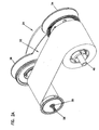
- a print ribbon supply item 10 is best seen in Figures 1-4 .
- the supply item 10 includes a print ribbon 12, preferably a multi-color print ribbon, that supplies the dye or ink used in the printing process.
- the ribbon 12 is wound onto a supply cylinder 14 that is cylindrical in shape.
- the ribbon 12 includes a take-up end 16 that is attached to a take-up cylinder 18 that is cylindrical in shape and upon which used ribbon is wound.
- the ribbon 12 is illustrated as being unused, with substantially the entire extent thereof wound onto the supply cylinder 14, and the end 16 of the ribbon 12 attached to the take-up cylinder 18 ready to take-up used ribbon.
- the supply cylinder 14 includes first and second ends 20a, 20b and is generally hollow from the first end to the second end.
- the take-up cylinder 18 includes first and second ends 22a, 22b and is generally hollow from the first end to the second end.
- the ends 20a, 20b, 22a, 22b of the cylinders 14, 18 are designed to facilitate loading of the cylinders 14, 18 onto a carrier 24 (to be later described in detail) in the proper orientation, thereby simplifying ribbon replacement. More preferably, a difference in the geometry of the ends of the cylinders 14, 18 is used to achieve the simplified replacement.
- the ends 20a, 20b of the cylinder 14 each define an opening having an area, with the area of the opening at the end 20a being substantially equal to the area of the opening at the end 20b.
- the ends 22a, 22b of the cylinder 18 each define an opening having an area.
- the end 22a of the cylinder 18 is closed by a wall 26 that forms part of a cap 28 that is connected to the end 22 of the cylinder 18.
- An opening 30 is provided in the wall 26.
- the area of the opening 30 at the end 22a is different than the area of the opening at the end 22b
- the area of the opening 30 is different than the area of the opening at the end 20a of the cylinder 14.
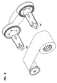
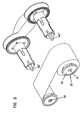
- each cylinder could be provided with a reduced area opening, as illustrated in Figure 9 , so that the supply and take-up cylinders can only be disposed on the carrier in one orientation.
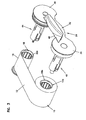
- the carrier 24 forms a structure upon which the cylinders 14, 18 and ribbon 12 can be mounted, and which can then be inserted into the printer.
- the carrier 24 includes a handle portion 32 disposed between opposite end regions 34, 36.
- the handle portion 32 and end regions 34, 36 are preferably formed of plastic to reduce the weight of the carrier 24.
- the end regions 34, 36 are generally circular in shape, and have diameters that are greater than the diameters of the cylinders 14, 18.
- the handle portion 32 comprises a connecting plate 38 that connects the end regions 34, 36.
- a plate 40 projects substantially perpendicularly from the plate 38 and from the end regions 34, 36.
- the plate 40 includes an upper surface that is curved upward, with the plate 40 forming a handle by which the carrier 24 can be carried in a persons hand.
- the carrier 24 includes a supply spindle assembly 42 that projects perpendicularly from the end region 34 and a take-up spindle assembly 44 that projects perpendicularly from the end region 36, as best seen in Figures 1 and 3 .
- the spindle assemblies 42 and 44 form means to support the cylinders 14, 18, respectively, and form means to determine which cylinder 14, 18 can be disposed on which spindle assembly.
- the spindle assembly 42 comprises a pin 46 and a supply spindle 48 surrounding the pin 46.
- the length of the spindle 48 and the length of the pin 46 are chosen such that the free end of the pin 46 projects past the end of the spindle 48, as shown in Figures 1 and 3 .
- the spindle 48 is rotatably mounted on the pin 46 so that the spindle 48 can rotate relative to the pin 46.
- the spindle 48 and pin 46 can be designed to rotate together if desired. Either configuration is possible, as long as the pin 46 projects past the end of the spindle 48.
- the spindle 48 is designed to receive the cylinder 14 thereon in such a manner that the cylinder 14 and spindle 48 rotate together with little or no relative rotation therebetween. Rotation between the cylinder 14 and the spindle 48 is prevented by ribs 50 provided on the interior surface of the cylinder and ribs 52 on the outer surface of the spindle 48. Resilient fingers 54 at the end of the spindle 48 snap over the ends of the ribs 50 on the cylinder 14, which are recessed from the end 20a of the cylinder 14, to fasten the cylinder 14 to the spindle 48. This type of connection mechanism between the cylinder 14 and spindle 48 is known in the art.
- an apertured disk 56 is connected to the spindle for rotation therewith.
- the disk 50 forms part of a mechanism, well know in the art, to monitor movements of the spindle 48 and thus movements of the supply cylinder 14 to be mounted thereon.
- the disk 56 is preferably spaced from the end region 34 to provide a space therebetween.
- the spindle assembly 44 like the spindle assembly 42, includes a pin 58 and a take-up spindle 60 surrounding the pin 58.
- the length of the spindle 60 and the length of the pin 58 are chosen such that the free end of the pin 58 projects past the end of the spindle 60, as shown in Figures 1 and 3 .
- the spindle 60 is rotatably mounted on the pin 58 so that the spindle 60 can rotate relative to the pin 58.
- the spindle 60 and pin 58 can be designed to rotate together if desired. Either configuration is possible, as long as the pin 58 projects past the end of the spindle 60.
- the spindle 60 is designed to receive the take-up cylinder 18 thereon in such a manner that the cylinder 18 and spindle 60 rotate together with little or no relative rotation therebetween.
- the connection between the cylinder 18 and spindle 60 is similar to the connection between the cylinder 14 and spindle 48.
- a gear 62 is connected to the spindle 60 for rotation therewith.
- the gear 62 is designed to be driven via a suitable driving mechanism to rotate the spindle 60 and thus the cylinder 18 to take-up used ribbon during use of the printer.
- the end of the pin 46 that projects past the end of the spindle 48 and the end of the pin 58 that projects past the end of the spindle 60 have different geometries from each other.
- different geometries includes differences in sizes, differences in shapes, and combinations of different sizes and shapes.
- the free end of the pin 46 is generally cylindrical so that, when viewed in an end plan view ( Figure 2B ), the pin 46 is generally circular.
- the maximum dimension D 1 e.g. the diameter for a cylindrical pin or other appropriate effective maximum dimension
- the free end of the pin 58 is generally fluted so that, when viewed in an end plan view ( Figure 2B ), the pin 58 is generally in the shape of a plus (+) sign, and the maximum dimension D 2 (i.e.
- the length of one of the legs defining the plus sign or other effective diameter for other shapes) of the pin 58 is such that the free end thereof is able to fit through the hole 30.
- the free end of the pin 58 could instead be cylindrical, but of a diameter that is different from the pin 46.
- each pin 46', 58' is circular in an end plan view, with the pin 58' having a smaller diameter than the pin 46'.
- the supply cylinder 14 could be provided with the hole so that the cylinder 14 is only insertable onto the spindle 48 in the orientation shown, while preventing insertion of the cylinder 14 onto the spindle 60.
- each cylinder 14, 18 could be provided with features to limit insertion thereof onto the respective appropriate spindle.
- the supply cylinder is formed with a rectangular shaped hole 31 in a wall 33 of an end cap 35.
- the hole 31 is sized to receive a free end of the pin 46" that is rectangular in shape, while the take-up cylinder is formed with the circular shaped hole 30 for interaction with a free end of the pin 58' that is circular.
- pins 46", 58' also alerts a user that there is a difference in the supply and take-up to make the user more wary when loading the supply item.
- Other shapes for the ends of the pins and the holes could also be used, for example triangular.
- the openings at the ends 20b, 22b in Figure 3 are illustrated as being of substantially the same size. However, it is also contemplated that the openings 20b, 22b at the ends could have different sizes. Further, it is contemplated that each end 20a, 20b, 22a, 22b could have different sized openings and/or different geometries to limit how the cylinders 14, 18 can be inserted onto the spindles.
- the take-up cylinder 18 could also be provided with memory means to store information pertaining to the supply item as well as other information.
- the memory means is preferably read/write memory to permit the reading of data from and the writing of data to, the memory means.
- the memory means can store information pertaining to the remaining amount of ribbon left on the supply cylinder, with the ribbon remaining information being decremented in the memory means based on print jobs using information provided by the printer controller.
- the memory means is preferably a radio frequency identification tag 64 mounted on the wall 26 of the cap 28.
- a suitable RF receiver/transmitter would be positioned in the printer adjacent to the end of the take-up cylinder 18 for reading data and writing data to the tag 64.
- the use and operation of RF identification tags is known from U.S. Patent 6,099,178 .
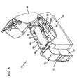
- FIGS 5-7 illustrate the print ribbon supply item 10 and carrier 24 in relation to a thermal printer 70.
- the printer 70 is related to the printer disclosed in U.S. Patent 5,762,431 , the entire disclosure of which is incorporated by reference.
- the printer 70 is used to print data and/or graphics onto plastic cards, for example financial (e.g. credit and debit) cards, drivers' licenses, national identification cards, and other cards.
- the printer 70 can also be provided with features to perform additional processing operations on the cards, including laminating the cards, printing bar codes, reading from and/or writing to magnetic stripes on the cards, and reading from and/or writing to an integrated circuit chip on the card.
- the printer 70 comprises a housing 72 having an input/output end 74 including an input station 76 that holds a plurality of cards and that feeds cards into the printer and an output station 78 for receiving printed cards from the printer.
- the housing 72 includes a pivotable cover 80 that pivots between an open position, shown in Figure 5 , allowing access to the interior of the printer, including a supply item receiving area 82, and a closed position (not shown) during use of the printer 70.
- a printer chassis 84 is disposed within the interior of the housing 72 for supporting components of the printer. Further information on this type of printer is disclosed in U.S. Patent 5,762,431 .
- the print ribbon 12 of the supply item 10 is supported by the carrier 24 within the area 82 of the printer 70.
- the print ribbon 12 is positioned to be heated by resistive dot elements on a thermal print head (not shown) which transfers thermally reactive dye or ink from the ribbon 12 to a card positioned adjacent the print head.
- a thermal print head (not shown) which transfers thermally reactive dye or ink from the ribbon 12 to a card positioned adjacent the print head.
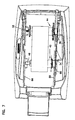
- the chassis 84 includes first and second side walls 86, 88 which define the receiving area 82 therebetween.
- the side wall 86 includes first and second support structures that project inward from the wall 86 for supporting the free ends of the pins 46, 58.
- Each support structure comprises a base section 90a, 90b that is closed at the bottom thereof to support the ends of the pins, for example pins 46, 58, thereon, and a guide section 92 composed of converging wall portions that converge toward the base section 90a, 90b.
- the converging construction of the guide sections 92 help to guide the respective free ends of the pins 46, 58 into the respective base sections 90a, 90b, thereby making it easier for an operator of the printer to insert the carrier 24 into the printer 70.
- the base sections 90a, 90b generally match the size of the ends of the pins 46, 58, in which case the size of the base section 90a for the end of the pin 46 is larger than the size of the base section 90b for the end of the pin 58.
- the side wall 88 of the chassis 84 includes cutouts 94a, 94b that support the spindle assemblies 42, 44 of the carrier 24.
- a gap 96 exists between the outside face of the chassis side wall 88 and the housing 72 structure.
- the housing 72 is provided with a cut-out 98.
- the handle portion 32 is disposed within the cut-out 98, with a gap 100 between the bottom of the handle portion 32 and the cut-out 98.
- the gap 100 allows room for a persons hand and/or fingers while installing or removing the carrier 24 and supply item 10.
- the construction of the handle portion 32 is such that it fits into the cut-out 98, thereby providing an indication to the user that the carrier and supply item are properly installed.
Landscapes
- Impression-Transfer Materials And Handling Thereof (AREA)
- Thermal Transfer Or Thermal Recording In General (AREA)
- Auxiliary Devices For And Details Of Packaging Control (AREA)
- Supplying Of Containers To The Packaging Station (AREA)
- Replacement Of Web Rolls (AREA)
- Accessory Devices And Overall Control Thereof (AREA)
- Manufacturing Of Electric Cables (AREA)
- Photoreceptors In Electrophotography (AREA)
- Crystals, And After-Treatments Of Crystals (AREA)
Claims (23)
- Dispositif d'alimentation pour des équipements de production de documents d'identification portant des données ou de documents financiers et chargeable sur une broche d'alimentation et une broche de réception d'un support, comprenant :un tambour d'alimentation ayant une première et une deuxième extrémité et ayant des nervures disposées sur une surface intérieure pour empêcher la rotation par rapport à la broche d'alimentation, la première extrémité définissant une première ouverture ayant une première géométrie et la deuxième extrémité définissant une deuxième ouverture ;un tambour de réception ayant une première et une deuxième extrémité et ayant des nervures disposées sur une surface intérieure pour empêcher la rotation par rapport à la broche de réception, la première extrémité du tambour de réception définissant une première ouverture ayant une deuxième géométrie, la deuxième géométrie étant différente de la première géométrie, et la deuxième extrémité définissant une deuxième ouverture ;un matériau en bande enroulé sur le tambour d'alimentation, le matériau en bande comprenant une extrémité de réception qui peut être fixée sur le tambour de réception ;dans lequel la première extrémité d'un au moins parmi le tambour d'alimentation ou le tambour de réception définissant un périmètre intérieur où la première extrémité est partiellement fermée lorsqu'elle est observée dans une vue en plan d'extrémité, la première ouverture à la première extrémité du tambour d'alimentation ou du tambour de réception étant disposée à l'intérieur du périmètre intérieur, la première ouverture ayant une surface inférieure à la surface de la deuxième ouverture à la deuxième extrémité du tambour d'alimentation ou du tambour de réception pour limiter la mesure dans laquelle les cylindres peuvent être connectés au support.
- Dispositif d'alimentation selon la revendication 1, dans lequel la première ouverture à la première extrémité du tambour d'alimentation définit une première surface, et la première ouverture à la première extrémité du tambour de réception définit une deuxième surface, et dans lequel la deuxième surface est inférieure à la première surface.
- Dispositif d'alimentation selon la revendication 1, dans lequel le matériau en bande comprend un ruban d'impression.
- Dispositif d'alimentation selon la revendication 3, dans lequel le ruban d'impression est un ruban d'impression polychrome.
- Dispositif d'alimentation selon la revendication 1, dans lequel le matériau en bande comprend un matériau parmi la liste suivante : un ruban effaceur, une surimpression holographique, et un matériau stratifié.
- Dispositif d'alimentation selon la revendication 2, dans lequel la deuxième ouverture de la deuxième extrémité du tambour d'alimentation définit une troisième surface, et la deuxième ouverture de la deuxième extrémité du tambour de réception définit une quatrième surface, et dans lequel la troisième surface est substantiellement égale à la quatrième surface.
- Dispositif d'alimentation selon la revendication 2, dans lequel la première extrémité du tambour de réception est fermée par une cloison, et dans lequel la deuxième géométrie est définie dans la cloison.
- Dispositif d'alimentation selon la revendication 7, dans lequel la cloison comporte un couvercle qui est fixé au tambour de réception en sa première extrémité.
- Dispositif d'alimentation selon la revendication 2, dans lequel la première extrémité du tambour d'alimentation est fermée par une cloison, et dans lequel la première géométrie est définie dans la cloison.
- Dispositif d'alimentation selon la revendication 9, dans lequel la cloison comporte un couvercle qui est fixé au tambour d'alimentation en sa première extrémité.
- Support pour un dispositif d'alimentation utilisé dans des équipements de production de documents d'identification portant des données ou de documents financiers, comprenant :une partie formant poignée ayant une première et une deuxième régions d'extrémité opposées ;une broche d'alimentation montée de manière à pouvoir entrer en rotation sur la partie formant poignée dans la première région d'extrémité pour tourner autour d'un premier axe de rotation, la broche d'alimentation ayant une première extrémité proche de la partie formant poignée et une deuxième extrémité distante de la première extrémité ;une première pointe dépassant de la deuxième extrémité de la broche d'alimentation généralement parallèlement au premier axe de rotation ;une broche de réception montée de manière à pouvoir entrer en rotation sur la partie formant poignée dans la deuxième région d'extrémité pour tourner autour d'un deuxième axe de rotation, la broche de réception ayant une première extrémité proche de la partie formant poignée et une deuxième extrémité distante de sa première extrémité ; etune deuxième pointe dépassant de la deuxième extrémité de la broche de réception généralement parallèlement au deuxième axe de rotation, et, lorsqu'elle est vue dans une vue en plan d'extrémité, la deuxième pointe a une géométrie qui est différente de la géométrie de la première pointe et comprenant en outre un dispositif d'alimentation tel que revendiqué dans l'une quelconque des revendications 1 à 10 qui lui est connecté ; le cylindre d'alimentation et le cylindre de réception chargés respectivement sur lesdites broche d'alimentation et broche de chargement.
- Support selon la revendication 11, dans lequel, lorsqu'elle est vue dans une vue en plan par d'extrémité, la deuxième pointe a une dimension maximale qui est inférieure à la dimension maximale de la première pointe.
- Support selon la revendication 12, dans lequel, lorsqu'elle est vue dans une vue en plan d'extrémité, la surface de la deuxième pointe est plus faible que la surface de la première pointe.
- Support selon la revendication 11, comprenant en outre une poignée raccordée à la partie formant poignée entre les régions d'extrémité, la poignée ayant une surface supérieure incurvée vers le haut.
- Support selon la revendication 11, dans lequel la première et la deuxième extrémité de la broche d'alimentation sont disposées d'un côté de la partie formant poignée, la première et la deuxième extrémité de la broche d'alimentation étant disposées du même côté de la partie formant poignée, et dans lequel la première et la deuxième extrémité de la broche de réception sont disposées du côté de la partie formant poignée, la première et la deuxième extrémité de la broche de réception étant disposées du même côté de la partie formant poignée,
- Procédé pour faciliter le chargement d'un dispositif d'alimentation pour des équipements de production de documents d'identification portant des données ou de documents financiers, le procédé comprenant :la mise en place d'un support selon la revendication 11, comprenant un sous-ensemble de broche d'alimentation et un sous-ensemble de broche de réception ;la mise en place d'un dispositif d'alimentation selon la revendication 1, comprenant un tambour d'alimentation, un tambour de réception et un matériau en bande enroulé autour du tambour d'alimentation et ayant une extrémité fixée au tambour de réception, ledit tambour d'alimentation étant prévu pour être disposé sur le sous-ensemble de broche d'alimentation et ledit tambour de réception étant prévu pour être disposé sur le sous-ensemble de broche de réception ;dans lequel au moins l'un parmi ledit tambour d'alimentation et ledit tambour de réception, et au moins un parmi ledit sous-ensemble de broche d'alimentation et ledit sous-ensemble de broche de réception sont conçus de telle manière que ledit tambour d'alimentation ou ledit tambour de réception peut seulement être disposé sur ledit sous-ensemble de broche d'alimentation ou sur ledit sous-ensemble de broche de réception, respectivement ; etl'insertion dudit support avec ledit tambour d'alimentation et ledit tambour de réception dans l'équipement de production de documents.
- Procédé selon la revendication 16, dans lequel ledit tambour de réception est conçu de manière à ne pouvoir être disposé que sur ledit sous-ensemble de broche de réception.
- Procédé selon la revendication 17, comprenant la fourniture dudit tambour de réception, dudit sous-ensemble de broche de réception, et dudit sous-ensemble de broche d'alimentation avec des géométries qui permettent audit tambour de réception d'être disposé sur ledit sous-ensemble de broche de réception et qui évitent que ledit tambour de réception ne soit disposé sur ledit sous-ensemble de broche d'alimentation.
- Équipement de production de documents d'identification portant des données ou de documents financiers comprenant :un bâti ;un support selon la revendication 11un dispositif d'alimentation selon la revendication 1 ;un châssis disposé dans le bâti, ledit châssis ayant une première et une deuxième parois latérales définissant entre elles une surface de réception d'un dispositif d'alimentation, ladite surface de réception d'un dispositif d'alimentation recevant au moins partiellement ledit support avec ledit dispositif d'alimentation, ledit support ayant un sous-ensemble de broche d'alimentation avec le tambour d'alimentation reçu sur le sous-ensemble de broche d'alimentation, et un sous-ensemble de broche de réception avec le tambour de réception reçu sur le sous-ensemble de broche de réception, avec un matériau en bande enroulé autour du tambour d'alimentation et ayant une extrémité de réception fixée audit tambour de réception ; etladite première paroi latérale comportant une première et une deuxième structures de support pour supporter les extrémités du sous-ensemble de broche d'alimentation et du sous-ensemble de broche de réception, respectivement, ladite première structure de support et ladite deuxième structure de support ayant des géométries différentes qui correspondent à des géométries différentes du sous-ensemble de broche d'alimentation et du sous-ensemble de broche de réception.
- Équipement de production selon la revendication 19, dans lequel ladite première structure de support et ladite deuxième structure de support comprennent chacune une section de base et une section de guidage qui converge vers ladite section de base.
- Équipement de production selon la revendication 19, comportant en outre un intervalle défini entre ladite deuxième paroi latérale dudit châssis et ledit bâti, et ledit intervalle étant dimensionné de manière à recevoir desdites régions d'extrémité dusupport lorsque ledit support est correctement monté sur ledit châssis.
- Équipement de production selon la revendication 19, dans lequel ledit bâtit comporte une section découpée, et dans lequel ledit support comporte une partie formant poignée qui est disposée dans ladite découpe lorsque ledit support est correctement monté sur ledit bâti, et dans lequel un intervalle est défini entre ladite partie formant poignée et une surface inférieure de ladite découpe.
- Équipement de production selon la revendication 22, dans lequel ladite partie formant poignée comporte une poignée avec une surface supérieure qui est configurée de manière à former un prolongement d'une structure adjacente du bâti.
Applications Claiming Priority (5)
| Application Number | Priority Date | Filing Date | Title |
|---|---|---|---|
| US613186 | 1990-11-14 | ||
| US40037002P | 2002-07-31 | 2002-07-31 | |
| US400370P | 2002-07-31 | ||
| US10/613,186 US6997629B2 (en) | 2002-07-31 | 2003-07-03 | Supply items for printers and the like, and method of loading supply items |
| PCT/US2003/023846 WO2004011268A1 (fr) | 2002-07-31 | 2003-07-30 | Fournitures pour imprimantes et analogues et procede de chargement desdites fournitures |
Publications (3)
| Publication Number | Publication Date |
|---|---|
| EP1534530A1 EP1534530A1 (fr) | 2005-06-01 |
| EP1534530B1 EP1534530B1 (fr) | 2009-12-09 |
| EP1534530B2 true EP1534530B2 (fr) | 2013-08-21 |
Family
ID=31191372
Family Applications (1)
| Application Number | Title | Priority Date | Filing Date |
|---|---|---|---|
| EP03772110.7A Expired - Lifetime EP1534530B2 (fr) | 2002-07-31 | 2003-07-30 | Fournitures pour imprimantes et analogues et procede de chargement desdites fournitures |
Country Status (8)
| Country | Link |
|---|---|
| US (1) | US6997629B2 (fr) |
| EP (1) | EP1534530B2 (fr) |
| JP (1) | JP4448091B2 (fr) |
| CN (1) | CN100396503C (fr) |
| AT (1) | ATE451244T1 (fr) |
| AU (1) | AU2003254267A1 (fr) |
| DE (1) | DE60330467D1 (fr) |
| WO (1) | WO2004011268A1 (fr) |
Families Citing this family (40)
| Publication number | Priority date | Publication date | Assignee | Title |
|---|---|---|---|---|
| US7018117B2 (en) * | 1999-01-25 | 2006-03-28 | Fargo Electronics, Inc. | Identification card printer ribbon cartridge |
| US7344325B2 (en) * | 1999-01-25 | 2008-03-18 | Fargo Electronics, Inc. | Identification card printer having ribbon cartridge with cleaner roller |
| US6832866B2 (en) * | 1999-01-25 | 2004-12-21 | Fargo Electronics, Inc. | Printer or laminator supply |
| US7154519B2 (en) * | 1999-01-25 | 2006-12-26 | Fargo Electronics, Inc. | Printer and ribbon cartridge |
| US7399131B2 (en) | 2001-03-05 | 2008-07-15 | Fargo Electronics, Inc. | Method and Device for forming an ink-receptive card substrate |
| US7430762B2 (en) * | 2002-03-01 | 2008-09-30 | Fargo Electronics, Inc. | Identification card manufacturing security |
| US6997629B2 (en) † | 2002-07-31 | 2006-02-14 | Datacard Corporation | Supply items for printers and the like, and method of loading supply items |
| US7620815B2 (en) * | 2003-02-21 | 2009-11-17 | Fargo Electronics, Inc. | Credential production using a secured consumable supply |
| US7878505B2 (en) * | 2003-08-19 | 2011-02-01 | Hid Global Corporation | Credential substrate rotator and processing module |
| WO2005026908A2 (fr) * | 2003-09-11 | 2005-03-24 | Fargo Electronics, Inc. | Systeme de fabrication de cartes d'identification, commande de provisions et rapport de diagnostic |
| US7934881B2 (en) | 2003-10-20 | 2011-05-03 | Zih Corp. | Replaceable ribbon supply and substrate cleaning apparatus |
| US20050084315A1 (en) | 2003-10-20 | 2005-04-21 | Zebra Technologies Corporation | Substrate cleaning apparatus and method |
| EP1743443B1 (fr) * | 2004-05-03 | 2013-09-25 | HID Global Corporation | Attribution geree et assuree des documents de reference |
| US7931678B2 (en) | 2004-12-08 | 2011-04-26 | Depuy Spine, Inc. | Hybrid spinal plates |
| JP2006168277A (ja) * | 2004-12-17 | 2006-06-29 | Brother Ind Ltd | インクシート巻回用円筒体及び中間連結体 |
| US7261254B2 (en) * | 2004-12-22 | 2007-08-28 | Eastman Kodak Company | Self-regulating media holder |
| US20060266873A1 (en) * | 2005-03-31 | 2006-11-30 | Global Plastics, A British Columbia General Partnership | Core Replacement System |
| US20070003351A1 (en) * | 2005-06-17 | 2007-01-04 | White Dennis R | Ribbon hub and spool assembly |
| US20070043684A1 (en) * | 2005-08-18 | 2007-02-22 | Fargo Electronics, Inc. | Central Management of a Credential Production System |
| US8099187B2 (en) | 2005-08-18 | 2012-01-17 | Hid Global Corporation | Securely processing and tracking consumable supplies and consumable material |
| US8834046B2 (en) * | 2007-03-08 | 2014-09-16 | Assa Abloy Ab | Inverted reverse-image transfer printing |
| US8646770B2 (en) | 2009-09-18 | 2014-02-11 | Hid Global Corporation | Card substrate rotator with lift mechanism |
| ES2371819B1 (es) * | 2010-02-10 | 2012-11-22 | Tkt Brainpower, S.L. | Sistema de sujeción de material laminar para máquinas trazadoras. |
| US8702328B2 (en) * | 2010-03-05 | 2014-04-22 | Datacard Corporation | Desktop card printer |
| TWI381950B (zh) * | 2010-05-21 | 2013-01-11 | Primax Electronics Ltd | 捲筒固定軸結構 |
| US10353645B2 (en) * | 2011-07-01 | 2019-07-16 | Entrust Datacard Corporation | User interface for a customized personalization document printer of an instant issuance system |
| WO2014007690A1 (fr) * | 2012-07-02 | 2014-01-09 | Sca Hygiene Products Ab | Élément central pour un rouleau de feuilles absorbantes |
| CN104786679B (zh) * | 2015-04-15 | 2017-10-13 | 重庆品胜科技有限公司 | 一种热转印碳带盒结构 |
| CN107787479A (zh) | 2015-06-25 | 2018-03-09 | 恩图鲁斯特咨询卡有限公司 | 即时发行系统的远程监控和管理 |
| JP6398932B2 (ja) * | 2015-09-28 | 2018-10-03 | ブラザー工業株式会社 | リボンカセット |
| CN108349279B (zh) * | 2015-11-13 | 2020-06-02 | 恩图鲁斯特咨询卡有限公司 | 带供应装置安装 |
| JP6108024B2 (ja) * | 2016-10-26 | 2017-04-05 | 株式会社湯山製作所 | 薬剤包装装置における巻回ロール及びその支持軸、並びにその支持軸への巻回ロールの取付構造 |
| CN112714698B (zh) * | 2018-09-20 | 2023-01-24 | 恩图鲁斯特有限公司 | 可折叠的色带补充盒 |
| WO2020189257A1 (fr) * | 2019-03-15 | 2020-09-24 | 株式会社タカゾノ | Corps d'enroulement |
| JP6613004B1 (ja) * | 2019-03-19 | 2019-11-27 | 株式会社タカゾノ | 巻回体と薬剤包装装置との組み合わせ、巻回体、芯体 |
| JP6644218B1 (ja) * | 2019-03-19 | 2020-02-12 | 株式会社タカゾノ | 巻回体と薬剤包装装置との組み合わせ、巻回体、芯体 |
| JP6644217B1 (ja) * | 2019-03-19 | 2020-02-12 | 株式会社タカゾノ | 巻回体と薬剤包装装置との組み合わせ、巻回体、芯体 |
| JP7340158B2 (ja) * | 2019-09-25 | 2023-09-07 | 大日本印刷株式会社 | リボンカセットの組合体及び転写システム |
| CA3153840A1 (fr) * | 2019-10-31 | 2021-05-06 | Takazono Corporation | Corps enroule, corps de noyau pour un corps enroule et combinaison du corps enroule et d'un arbre de support |
| US20250206565A1 (en) * | 2023-12-20 | 2025-06-26 | Zebra Technologies Corporation | Media Supply with Self-Locking Media Core for Media Processing Devices |
Citations (6)
| Publication number | Priority date | Publication date | Assignee | Title |
|---|---|---|---|---|
| US4131373A (en) † | 1977-06-10 | 1978-12-26 | Liquid Paper Corporation | Typewriter ribbon cartridge |
| EP0435108A2 (fr) † | 1989-12-25 | 1991-07-03 | Hitachi, Ltd. | Cassette pour ruban d'écriture thermique |
| JPH10329378A (ja) † | 1997-05-29 | 1998-12-15 | Sharp Corp | 感熱記録用インクリボンの取付構造 |
| US6152625A (en) † | 1999-07-27 | 2000-11-28 | Fargo Electronics, Inc. | Sensor hub for a print ribbon supply roll and method |
| US6257780B1 (en) † | 1998-01-06 | 2001-07-10 | Brother Kogyo Kabushiki Kaisha | Ink ribbon cartridge having one undetachable spool and idle rotation preventing structure |
| WO2004011268A1 (fr) † | 2002-07-31 | 2004-02-05 | Datacard Corporation | Fournitures pour imprimantes et analogues et procede de chargement desdites fournitures |
Family Cites Families (12)
| Publication number | Priority date | Publication date | Assignee | Title |
|---|---|---|---|---|
| US3604549A (en) * | 1968-07-16 | 1971-09-14 | Ibm | Dual feed rate ribbon mechanism and supply cartridge therefor |
| JPS58155246U (ja) * | 1982-04-12 | 1983-10-17 | ブラザー工業株式会社 | 熱転写プリンタ |
| GB9401544D0 (en) * | 1994-01-27 | 1994-03-23 | Ici Plc | Thermal transfer ribbon cassette system |
| JP3330476B2 (ja) | 1995-10-18 | 2002-09-30 | 株式会社 沖情報システムズ | アダプタケースとそのアダプタケースをインクリボン装着に用いる券処理装置 |
| US5755519A (en) * | 1996-12-04 | 1998-05-26 | Fargo Electronics, Inc. | Printer ribbon identification sensor |
| JP3613917B2 (ja) * | 1997-01-06 | 2005-01-26 | ブラザー工業株式会社 | インクリボンカートリッジ |
| US5762431A (en) * | 1997-02-10 | 1998-06-09 | Datacard Corporation | Thermal printer and method for using |
| US6099178A (en) * | 1998-08-12 | 2000-08-08 | Eastman Kodak Company | Printer with media supply spool adapted to sense type of media, and method of assembling same |
| US6109801A (en) * | 1999-03-18 | 2000-08-29 | Eltron International, Inc. | Ribbon core and spindle |
| US6082914A (en) * | 1999-05-27 | 2000-07-04 | Printronix, Inc. | Thermal printer and drive system for controlling print ribbon velocity and tension |
| ATE362429T1 (de) * | 2000-03-31 | 2007-06-15 | Brother Ind Ltd | Bildformungsgerät und in das bildformungsgerät montierte farbbandkassette |
| US6422770B1 (en) * | 2000-07-18 | 2002-07-23 | Nashua Corporation | Universal inked ribbon assembly for printing apparatus |
-
2003
- 2003-07-03 US US10/613,186 patent/US6997629B2/en not_active Expired - Lifetime
- 2003-07-30 JP JP2005505642A patent/JP4448091B2/ja not_active Expired - Fee Related
- 2003-07-30 EP EP03772110.7A patent/EP1534530B2/fr not_active Expired - Lifetime
- 2003-07-30 DE DE60330467T patent/DE60330467D1/de not_active Expired - Lifetime
- 2003-07-30 CN CNB038183080A patent/CN100396503C/zh not_active Expired - Fee Related
- 2003-07-30 AT AT03772110T patent/ATE451244T1/de not_active IP Right Cessation
- 2003-07-30 WO PCT/US2003/023846 patent/WO2004011268A1/fr not_active Ceased
- 2003-07-30 AU AU2003254267A patent/AU2003254267A1/en not_active Abandoned
Patent Citations (6)
| Publication number | Priority date | Publication date | Assignee | Title |
|---|---|---|---|---|
| US4131373A (en) † | 1977-06-10 | 1978-12-26 | Liquid Paper Corporation | Typewriter ribbon cartridge |
| EP0435108A2 (fr) † | 1989-12-25 | 1991-07-03 | Hitachi, Ltd. | Cassette pour ruban d'écriture thermique |
| JPH10329378A (ja) † | 1997-05-29 | 1998-12-15 | Sharp Corp | 感熱記録用インクリボンの取付構造 |
| US6257780B1 (en) † | 1998-01-06 | 2001-07-10 | Brother Kogyo Kabushiki Kaisha | Ink ribbon cartridge having one undetachable spool and idle rotation preventing structure |
| US6152625A (en) † | 1999-07-27 | 2000-11-28 | Fargo Electronics, Inc. | Sensor hub for a print ribbon supply roll and method |
| WO2004011268A1 (fr) † | 2002-07-31 | 2004-02-05 | Datacard Corporation | Fournitures pour imprimantes et analogues et procede de chargement desdites fournitures |
Also Published As
| Publication number | Publication date |
|---|---|
| EP1534530A1 (fr) | 2005-06-01 |
| EP1534530B1 (fr) | 2009-12-09 |
| US6997629B2 (en) | 2006-02-14 |
| JP2005534547A (ja) | 2005-11-17 |
| WO2004011268A1 (fr) | 2004-02-05 |
| ATE451244T1 (de) | 2009-12-15 |
| CN1671558A (zh) | 2005-09-21 |
| DE60330467D1 (de) | 2010-01-21 |
| AU2003254267A1 (en) | 2004-02-16 |
| HK1076271A1 (en) | 2006-01-13 |
| CN100396503C (zh) | 2008-06-25 |
| US20040022572A1 (en) | 2004-02-05 |
| JP4448091B2 (ja) | 2010-04-07 |
Similar Documents
| Publication | Publication Date | Title |
|---|---|---|
| EP1534530B2 (fr) | Fournitures pour imprimantes et analogues et procede de chargement desdites fournitures | |
| US7342597B2 (en) | Radio frequency identification tags on consumable items used in printers and related equipment | |
| EP1792740B1 (fr) | Dispositif d'impression de ruban et cassette a ruban | |
| EP1813431B1 (fr) | Cassette a ruban et imprimante sur ruban | |
| CN100522751C (zh) | 打印机带盒 | |
| EP4382302B1 (fr) | Appareil d'impression | |
| CN101025793B (zh) | 标签带和带印迹标签标记带 | |
| EP0929403B1 (fr) | Ensemble pour la configuration automatique d'une imprimante et supports correspondants | |
| US6364552B1 (en) | Method and apparatus for recording used labels | |
| HK1076271B (en) | Supply items for printers and the like, and method of loading supply items | |
| HK1076271C (en) | Supply items for printers and the like, and method of loading supply items | |
| EP1041024A2 (fr) | Dispositif d'impression de ruban, cassette pour ruban et dispositif d'impression de ruban avec cette cassette pour ruban, et dispositif de coupe de ruban | |
| WO1999044834A1 (fr) | Cartouche de ruban a transfert thermique | |
| JP2000185435A (ja) | テ―プ印字装置 | |
| HK1074425B (en) | Consumable items and radio frequency identification tags used thereon |
Legal Events
| Date | Code | Title | Description |
|---|---|---|---|
| PUAI | Public reference made under article 153(3) epc to a published international application that has entered the european phase |
Free format text: ORIGINAL CODE: 0009012 |
|
| 17P | Request for examination filed |
Effective date: 20050223 |
|
| AK | Designated contracting states |
Kind code of ref document: A1 Designated state(s): AT BE BG CH CY CZ DE DK EE ES FI FR GB GR HU IE IT LI LU MC NL PT RO SE SI SK TR |
|
| AX | Request for extension of the european patent |
Extension state: AL LT LV MK |
|
| DAX | Request for extension of the european patent (deleted) | ||
| REG | Reference to a national code |
Ref country code: HK Ref legal event code: DE Ref document number: 1076271 Country of ref document: HK |
|
| 17Q | First examination report despatched |
Effective date: 20060921 |
|
| RIN1 | Information on inventor provided before grant (corrected) |
Inventor name: JOHNSON, BRETT, RYAN Inventor name: CLEMENS, BRIAN Inventor name: ASTWOOD, JENNIFER Inventor name: ANGELL, CHARLES, AUSTEN Inventor name: BUNGERT, LYLE, C. |
|
| GRAP | Despatch of communication of intention to grant a patent |
Free format text: ORIGINAL CODE: EPIDOSNIGR1 |
|
| GRAS | Grant fee paid |
Free format text: ORIGINAL CODE: EPIDOSNIGR3 |
|
| GRAA | (expected) grant |
Free format text: ORIGINAL CODE: 0009210 |
|
| AK | Designated contracting states |
Kind code of ref document: B1 Designated state(s): AT BE BG CH CY CZ DE DK EE ES FI FR GB GR HU IE IT LI LU MC NL PT RO SE SI SK TR |
|
| REG | Reference to a national code |
Ref country code: GB Ref legal event code: FG4D |
|
| REG | Reference to a national code |
Ref country code: CH Ref legal event code: EP |
|
| REG | Reference to a national code |
Ref country code: IE Ref legal event code: FG4D |
|
| REF | Corresponds to: |
Ref document number: 60330467 Country of ref document: DE Date of ref document: 20100121 Kind code of ref document: P |
|
| PLBI | Opposition filed |
Free format text: ORIGINAL CODE: 0009260 |
|
| REG | Reference to a national code |
Ref country code: NL Ref legal event code: VDEP Effective date: 20091209 |
|
| PG25 | Lapsed in a contracting state [announced via postgrant information from national office to epo] |
Ref country code: SE Free format text: LAPSE BECAUSE OF FAILURE TO SUBMIT A TRANSLATION OF THE DESCRIPTION OR TO PAY THE FEE WITHIN THE PRESCRIBED TIME-LIMIT Effective date: 20091209 Ref country code: FI Free format text: LAPSE BECAUSE OF FAILURE TO SUBMIT A TRANSLATION OF THE DESCRIPTION OR TO PAY THE FEE WITHIN THE PRESCRIBED TIME-LIMIT Effective date: 20091209 |
|
| 26 | Opposition filed |
Opponent name: EAGLE TECHNOLOGIES LIMITED Effective date: 20100325 |
|
| PG25 | Lapsed in a contracting state [announced via postgrant information from national office to epo] |
Ref country code: SI Free format text: LAPSE BECAUSE OF FAILURE TO SUBMIT A TRANSLATION OF THE DESCRIPTION OR TO PAY THE FEE WITHIN THE PRESCRIBED TIME-LIMIT Effective date: 20091209 |
|
| PG25 | Lapsed in a contracting state [announced via postgrant information from national office to epo] |
Ref country code: AT Free format text: LAPSE BECAUSE OF FAILURE TO SUBMIT A TRANSLATION OF THE DESCRIPTION OR TO PAY THE FEE WITHIN THE PRESCRIBED TIME-LIMIT Effective date: 20091209 |
|
| REG | Reference to a national code |
Ref country code: HK Ref legal event code: GR Ref document number: 1076271 Country of ref document: HK |
|
| PG25 | Lapsed in a contracting state [announced via postgrant information from national office to epo] |
Ref country code: EE Free format text: LAPSE BECAUSE OF FAILURE TO SUBMIT A TRANSLATION OF THE DESCRIPTION OR TO PAY THE FEE WITHIN THE PRESCRIBED TIME-LIMIT Effective date: 20091209 Ref country code: PT Free format text: LAPSE BECAUSE OF FAILURE TO SUBMIT A TRANSLATION OF THE DESCRIPTION OR TO PAY THE FEE WITHIN THE PRESCRIBED TIME-LIMIT Effective date: 20100409 Ref country code: BG Free format text: LAPSE BECAUSE OF FAILURE TO SUBMIT A TRANSLATION OF THE DESCRIPTION OR TO PAY THE FEE WITHIN THE PRESCRIBED TIME-LIMIT Effective date: 20100309 Ref country code: RO Free format text: LAPSE BECAUSE OF FAILURE TO SUBMIT A TRANSLATION OF THE DESCRIPTION OR TO PAY THE FEE WITHIN THE PRESCRIBED TIME-LIMIT Effective date: 20091209 Ref country code: ES Free format text: LAPSE BECAUSE OF FAILURE TO SUBMIT A TRANSLATION OF THE DESCRIPTION OR TO PAY THE FEE WITHIN THE PRESCRIBED TIME-LIMIT Effective date: 20100320 Ref country code: NL Free format text: LAPSE BECAUSE OF FAILURE TO SUBMIT A TRANSLATION OF THE DESCRIPTION OR TO PAY THE FEE WITHIN THE PRESCRIBED TIME-LIMIT Effective date: 20091209 |
|
| REG | Reference to a national code |
Ref country code: GB Ref legal event code: S75Z Free format text: APPLICATION OPEN FOR OPPOSITION |
|
| PG25 | Lapsed in a contracting state [announced via postgrant information from national office to epo] |
Ref country code: BE Free format text: LAPSE BECAUSE OF FAILURE TO SUBMIT A TRANSLATION OF THE DESCRIPTION OR TO PAY THE FEE WITHIN THE PRESCRIBED TIME-LIMIT Effective date: 20091209 Ref country code: SK Free format text: LAPSE BECAUSE OF FAILURE TO SUBMIT A TRANSLATION OF THE DESCRIPTION OR TO PAY THE FEE WITHIN THE PRESCRIBED TIME-LIMIT Effective date: 20091209 Ref country code: CZ Free format text: LAPSE BECAUSE OF FAILURE TO SUBMIT A TRANSLATION OF THE DESCRIPTION OR TO PAY THE FEE WITHIN THE PRESCRIBED TIME-LIMIT Effective date: 20091209 |
|
| PLAX | Notice of opposition and request to file observation + time limit sent |
Free format text: ORIGINAL CODE: EPIDOSNOBS2 |
|
| PG25 | Lapsed in a contracting state [announced via postgrant information from national office to epo] |
Ref country code: GR Free format text: LAPSE BECAUSE OF FAILURE TO SUBMIT A TRANSLATION OF THE DESCRIPTION OR TO PAY THE FEE WITHIN THE PRESCRIBED TIME-LIMIT Effective date: 20100310 Ref country code: CY Free format text: LAPSE BECAUSE OF FAILURE TO SUBMIT A TRANSLATION OF THE DESCRIPTION OR TO PAY THE FEE WITHIN THE PRESCRIBED TIME-LIMIT Effective date: 20091209 |
|
| PGFP | Annual fee paid to national office [announced via postgrant information from national office to epo] |
Ref country code: GB Payment date: 20100616 Year of fee payment: 8 |
|
| PG25 | Lapsed in a contracting state [announced via postgrant information from national office to epo] |
Ref country code: DK Free format text: LAPSE BECAUSE OF FAILURE TO SUBMIT A TRANSLATION OF THE DESCRIPTION OR TO PAY THE FEE WITHIN THE PRESCRIBED TIME-LIMIT Effective date: 20091209 |
|
| PLAF | Information modified related to communication of a notice of opposition and request to file observations + time limit |
Free format text: ORIGINAL CODE: EPIDOSCOBS2 |
|
| PG25 | Lapsed in a contracting state [announced via postgrant information from national office to epo] |
Ref country code: MC Free format text: LAPSE BECAUSE OF NON-PAYMENT OF DUE FEES Effective date: 20100731 |
|
| REG | Reference to a national code |
Ref country code: CH Ref legal event code: PL |
|
| PG25 | Lapsed in a contracting state [announced via postgrant information from national office to epo] |
Ref country code: IT Free format text: LAPSE BECAUSE OF FAILURE TO SUBMIT A TRANSLATION OF THE DESCRIPTION OR TO PAY THE FEE WITHIN THE PRESCRIBED TIME-LIMIT Effective date: 20091209 |
|
| PG25 | Lapsed in a contracting state [announced via postgrant information from national office to epo] |
Ref country code: CH Free format text: LAPSE BECAUSE OF NON-PAYMENT OF DUE FEES Effective date: 20100731 Ref country code: LI Free format text: LAPSE BECAUSE OF NON-PAYMENT OF DUE FEES Effective date: 20100731 |
|
| PLBB | Reply of patent proprietor to notice(s) of opposition received |
Free format text: ORIGINAL CODE: EPIDOSNOBS3 |
|
| PG25 | Lapsed in a contracting state [announced via postgrant information from national office to epo] |
Ref country code: IE Free format text: LAPSE BECAUSE OF NON-PAYMENT OF DUE FEES Effective date: 20100730 |
|
| PLAB | Opposition data, opponent's data or that of the opponent's representative modified |
Free format text: ORIGINAL CODE: 0009299OPPO |
|
| R26 | Opposition filed (corrected) |
Opponent name: EAGLE TECHNOLOGIES LIMITED Effective date: 20100325 |
|
| GBPC | Gb: european patent ceased through non-payment of renewal fee |
Effective date: 20110730 |
|
| REG | Reference to a national code |
Ref country code: GB Ref legal event code: S72Z Free format text: PATENT REVOKED; PATENT REVOKED AS INSTRUCTED BY COURT ORDER OF 30 MARCH 2011 (HC10C0081) Ref country code: GB Ref legal event code: S75Z Free format text: APPLICATION WITHDRAWN; APPLICATION FOR AMENDMENT UNDER SECTION 75 BEFORE THE COURT FILED ON 15 JULY 2010(HC10C00081) WITHDRAWN |
|
| PG25 | Lapsed in a contracting state [announced via postgrant information from national office to epo] |
Ref country code: GB Free format text: THE PATENT HAS BEEN ANNULLED BY A DECISION OF A NATIONAL AUTHORITY Effective date: 20110330 |
|
| PLAB | Opposition data, opponent's data or that of the opponent's representative modified |
Free format text: ORIGINAL CODE: 0009299OPPO |
|
| R26 | Opposition filed (corrected) |
Opponent name: EAGLE TECHNOLOGIES LIMITED Effective date: 20100325 |
|
| PG25 | Lapsed in a contracting state [announced via postgrant information from national office to epo] |
Ref country code: HU Free format text: LAPSE BECAUSE OF FAILURE TO SUBMIT A TRANSLATION OF THE DESCRIPTION OR TO PAY THE FEE WITHIN THE PRESCRIBED TIME-LIMIT Effective date: 20100610 Ref country code: LU Free format text: LAPSE BECAUSE OF NON-PAYMENT OF DUE FEES Effective date: 20100730 |
|
| PG25 | Lapsed in a contracting state [announced via postgrant information from national office to epo] |
Ref country code: TR Free format text: LAPSE BECAUSE OF FAILURE TO SUBMIT A TRANSLATION OF THE DESCRIPTION OR TO PAY THE FEE WITHIN THE PRESCRIBED TIME-LIMIT Effective date: 20091209 |
|
| PUAH | Patent maintained in amended form |
Free format text: ORIGINAL CODE: 0009272 |
|
| STAA | Information on the status of an ep patent application or granted ep patent |
Free format text: STATUS: PATENT MAINTAINED AS AMENDED |
|
| 27A | Patent maintained in amended form |
Effective date: 20130821 |
|
| AK | Designated contracting states |
Kind code of ref document: B2 Designated state(s): AT BE BG CH CY CZ DE DK EE ES FI FR GB GR HU IE IT LI LU MC NL PT RO SE SI SK TR |
|
| REG | Reference to a national code |
Ref country code: DE Ref legal event code: R102 Ref document number: 60330467 Country of ref document: DE Effective date: 20130821 |
|
| REG | Reference to a national code |
Ref country code: HK Ref legal event code: AM43 Ref document number: 1076271 Country of ref document: HK |
|
| REG | Reference to a national code |
Ref country code: FR Ref legal event code: PLFP Year of fee payment: 13 |
|
| REG | Reference to a national code |
Ref country code: FR Ref legal event code: PLFP Year of fee payment: 14 |
|
| REG | Reference to a national code |
Ref country code: FR Ref legal event code: PLFP Year of fee payment: 15 |
|
| REG | Reference to a national code |
Ref country code: FR Ref legal event code: PLFP Year of fee payment: 16 |
|
| PGFP | Annual fee paid to national office [announced via postgrant information from national office to epo] |
Ref country code: DE Payment date: 20190729 Year of fee payment: 17 |
|
| PGFP | Annual fee paid to national office [announced via postgrant information from national office to epo] |
Ref country code: FR Payment date: 20200727 Year of fee payment: 18 |
|
| REG | Reference to a national code |
Ref country code: DE Ref legal event code: R119 Ref document number: 60330467 Country of ref document: DE |
|
| PG25 | Lapsed in a contracting state [announced via postgrant information from national office to epo] |
Ref country code: DE Free format text: LAPSE BECAUSE OF NON-PAYMENT OF DUE FEES Effective date: 20210202 |
|
| PG25 | Lapsed in a contracting state [announced via postgrant information from national office to epo] |
Ref country code: FR Free format text: LAPSE BECAUSE OF NON-PAYMENT OF DUE FEES Effective date: 20210731 |