EP1534379B1 - Kappe für einen schlauch zur abgabe von flüssigkeit - Google Patents
Kappe für einen schlauch zur abgabe von flüssigkeit Download PDFInfo
- Publication number
- EP1534379B1 EP1534379B1 EP03784671A EP03784671A EP1534379B1 EP 1534379 B1 EP1534379 B1 EP 1534379B1 EP 03784671 A EP03784671 A EP 03784671A EP 03784671 A EP03784671 A EP 03784671A EP 1534379 B1 EP1534379 B1 EP 1534379B1
- Authority
- EP
- European Patent Office
- Prior art keywords
- tube
- cap
- liquid
- liquid medicine
- absorption member
- Prior art date
- Legal status (The legal status is an assumption and is not a legal conclusion. Google has not performed a legal analysis and makes no representation as to the accuracy of the status listed.)
- Expired - Lifetime
Links
- 239000007788 liquid Substances 0.000 title claims description 101
- 239000003814 drug Substances 0.000 claims description 62
- 238000010521 absorption reaction Methods 0.000 claims description 34
- 239000000463 material Substances 0.000 claims description 13
- 238000003825 pressing Methods 0.000 claims description 9
- 239000002657 fibrous material Substances 0.000 claims description 3
- 239000000088 plastic resin Substances 0.000 claims description 3
- 230000000903 blocking effect Effects 0.000 claims description 2
- 238000002347 injection Methods 0.000 description 19
- 239000007924 injection Substances 0.000 description 19
- 238000003780 insertion Methods 0.000 description 6
- 230000037431 insertion Effects 0.000 description 6
- 238000004891 communication Methods 0.000 description 3
- 230000002209 hydrophobic effect Effects 0.000 description 3
- 230000007423 decrease Effects 0.000 description 2
- 230000000694 effects Effects 0.000 description 2
- 239000012466 permeate Substances 0.000 description 2
- 239000000047 product Substances 0.000 description 2
- 238000009423 ventilation Methods 0.000 description 2
- 229920000877 Melamine resin Polymers 0.000 description 1
- 230000002745 absorbent Effects 0.000 description 1
- 239000002250 absorbent Substances 0.000 description 1
- 238000007792 addition Methods 0.000 description 1
- 239000000853 adhesive Substances 0.000 description 1
- 230000001070 adhesive effect Effects 0.000 description 1
- 239000008280 blood Substances 0.000 description 1
- 210000004369 blood Anatomy 0.000 description 1
- 230000003247 decreasing effect Effects 0.000 description 1
- 239000004744 fabric Substances 0.000 description 1
- 239000006261 foam material Substances 0.000 description 1
- IVJISJACKSSFGE-UHFFFAOYSA-N formaldehyde;1,3,5-triazine-2,4,6-triamine Chemical compound O=C.NC1=NC(N)=NC(N)=N1 IVJISJACKSSFGE-UHFFFAOYSA-N 0.000 description 1
- 238000000034 method Methods 0.000 description 1
- 238000012986 modification Methods 0.000 description 1
- 230000004048 modification Effects 0.000 description 1
- 230000000149 penetrating effect Effects 0.000 description 1
- 239000004033 plastic Substances 0.000 description 1
- 229920003023 plastic Polymers 0.000 description 1
- -1 polytetrafluoroethylene Polymers 0.000 description 1
- 229920001343 polytetrafluoroethylene Polymers 0.000 description 1
- 239000004810 polytetrafluoroethylene Substances 0.000 description 1
- 238000012545 processing Methods 0.000 description 1
- 230000001954 sterilising effect Effects 0.000 description 1
- 238000004659 sterilization and disinfection Methods 0.000 description 1
- 239000004575 stone Substances 0.000 description 1
Images
Classifications
-
- A—HUMAN NECESSITIES
- A61—MEDICAL OR VETERINARY SCIENCE; HYGIENE
- A61M—DEVICES FOR INTRODUCING MEDIA INTO, OR ONTO, THE BODY; DEVICES FOR TRANSDUCING BODY MEDIA OR FOR TAKING MEDIA FROM THE BODY; DEVICES FOR PRODUCING OR ENDING SLEEP OR STUPOR
- A61M5/00—Devices for bringing media into the body in a subcutaneous, intra-vascular or intramuscular way; Accessories therefor, e.g. filling or cleaning devices, arm-rests
- A61M5/36—Devices for bringing media into the body in a subcutaneous, intra-vascular or intramuscular way; Accessories therefor, e.g. filling or cleaning devices, arm-rests with means for eliminating or preventing injection or infusion of air into body
-
- A—HUMAN NECESSITIES
- A61—MEDICAL OR VETERINARY SCIENCE; HYGIENE
- A61M—DEVICES FOR INTRODUCING MEDIA INTO, OR ONTO, THE BODY; DEVICES FOR TRANSDUCING BODY MEDIA OR FOR TAKING MEDIA FROM THE BODY; DEVICES FOR PRODUCING OR ENDING SLEEP OR STUPOR
- A61M39/00—Tubes, tube connectors, tube couplings, valves, access sites or the like, specially adapted for medical use
- A61M39/20—Closure caps or plugs for connectors or open ends of tubes
-
- A—HUMAN NECESSITIES
- A61—MEDICAL OR VETERINARY SCIENCE; HYGIENE
- A61M—DEVICES FOR INTRODUCING MEDIA INTO, OR ONTO, THE BODY; DEVICES FOR TRANSDUCING BODY MEDIA OR FOR TAKING MEDIA FROM THE BODY; DEVICES FOR PRODUCING OR ENDING SLEEP OR STUPOR
- A61M5/00—Devices for bringing media into the body in a subcutaneous, intra-vascular or intramuscular way; Accessories therefor, e.g. filling or cleaning devices, arm-rests
- A61M5/14—Infusion devices, e.g. infusing by gravity; Blood infusion; Accessories therefor
- A61M2005/1401—Functional features
- A61M2005/1403—Flushing or purging
-
- A—HUMAN NECESSITIES
- A61—MEDICAL OR VETERINARY SCIENCE; HYGIENE
- A61M—DEVICES FOR INTRODUCING MEDIA INTO, OR ONTO, THE BODY; DEVICES FOR TRANSDUCING BODY MEDIA OR FOR TAKING MEDIA FROM THE BODY; DEVICES FOR PRODUCING OR ENDING SLEEP OR STUPOR
- A61M39/00—Tubes, tube connectors, tube couplings, valves, access sites or the like, specially adapted for medical use
- A61M39/10—Tube connectors; Tube couplings
-
- A—HUMAN NECESSITIES
- A61—MEDICAL OR VETERINARY SCIENCE; HYGIENE
- A61M—DEVICES FOR INTRODUCING MEDIA INTO, OR ONTO, THE BODY; DEVICES FOR TRANSDUCING BODY MEDIA OR FOR TAKING MEDIA FROM THE BODY; DEVICES FOR PRODUCING OR ENDING SLEEP OR STUPOR
- A61M5/00—Devices for bringing media into the body in a subcutaneous, intra-vascular or intramuscular way; Accessories therefor, e.g. filling or cleaning devices, arm-rests
- A61M5/36—Devices for bringing media into the body in a subcutaneous, intra-vascular or intramuscular way; Accessories therefor, e.g. filling or cleaning devices, arm-rests with means for eliminating or preventing injection or infusion of air into body
- A61M5/38—Devices for bringing media into the body in a subcutaneous, intra-vascular or intramuscular way; Accessories therefor, e.g. filling or cleaning devices, arm-rests with means for eliminating or preventing injection or infusion of air into body using hydrophilic or hydrophobic filters
- A61M5/385—Devices for bringing media into the body in a subcutaneous, intra-vascular or intramuscular way; Accessories therefor, e.g. filling or cleaning devices, arm-rests with means for eliminating or preventing injection or infusion of air into body using hydrophilic or hydrophobic filters using hydrophobic filters
Definitions
- the present invention relates to a cap for a liquid supplying tube, and more particularly, to a cap enabling the exhaust of air existing in a tube before supplying a liquid in a state where the cap is installed in the tube.
- a tube is connected to a liquid supplying apparatus that functions to supply a liquid medicine (or blood) into a human body.
- a distal end of the tube is plugged by a cap before injection of the medicine.
- the tube is then used by removing the cap therefrom and connecting the distal end of the tube to an inlet of a member (e.g., catheter), which has been directly connected to the human body, when the medicine is injected.
- a member e.g., catheter
- an injection liquid medicine
- an injection liquid medicine
- a ventilation device for a medical liquid-system is disclosed.
- the ventilation device can be applied to the end of a tube and comprises a hydrophilic layer and a hydrophobic layer which are arranged attached to each other perpendicular to the axis of the tube. If dry, both layers are permeable for air such that air may escape from the tube end when a liquid is inserted.
- the two layers are arranged such that potential liquid in the tube first reaches the hydrophilic layer which becomes air-tight when wetted. Then, liquid is prevented from exiting the tube by the hydrophobic layer attached to the hydrophilic layer.
- a structure proposed by the present inventor in order to solve the problem is disclosed in Korean Utility Model Registration No. 20-0226977 .
- a distal end cap is provided with an air pass filter and an air vent to conveniently exhaust air existing in a tube. That is, as a liquid medicine is supplied to the tube from a liquid supplying apparatus, air existing in the tube is pushed by the supplied liquid medicine and then moves toward the cap. Consequently, the air escapes from the tube through the air pass filter and the air vent. Since only the air escapes therefrom, it is possible to easily exhaust the air without a resulting loss in the liquid medicine.
- Such a structure has remarkable effects superior to those obtained by conventional caps. However, there are sometimes cases where air remains between portions of liquid medicine within the tube.
- An object of the present invention is to provide a distal end cap having excellent effects, which further improves the structure of the existing distal end cap proposed by the present inventor, and more specifically, to provide a cap for a distal end of a tube, which can easily exhaust air that may exist between portions of liquid in the tube.
- the present invention provides a distal end cap that can effectively exhaust the air even in such a case.
- the present inventor considered that in such a case where air exists behind a portion of liquid that has first reached the distal end of the tube, the amount of the portion of liquid is small, and based on this consideration, designed a distal end cap equipped with a liquid absorption material (absorbent) that can absorb the portion of liquid.
- a cap for a tube which is connected to a distal end of the tube, and comprises a passage for communicating with the tube and the outside, a liquid absorption member disposed in the passage, and a gas permeable and liquid impermeable filter for blocking the passage at a (downstream) position farther than the liquid absorption member from the tube.
- the liquid absorption is configured to surround the passage.
- the liquid absorption member may be made of a sponge material or fiber material.
- the filter may be made of a porous plastic resin material.
- the cap may further comprise a main body which includes an outer wall and a connection projection provided radially inward of the outer wall, and in which the other end opposite to an end of the main body with the connection projection provided thereon is open, and the passage is formed and the liquid absorption member is received; and a closure which is connected to close the other open end of the main body and includes an exhaust hole that communicates with the passage and is blocked by the filter.
- connection projection may comprise a tube extending inward and outward of the end of the outer wall, and the absorption member is fixedly fitted between the outer wall of the main body and an inward extension of the connection projection.
- the closure may further comprise an extension for isolating the absorption member and the filter from each other.
- the distal end cap may be connected to an injection quantity adjustor with a detachable clip installed thereon, and also connected to the clip so that they can be removed together.
- a liquid medicine supplying apparatus for supplying a liquid medicine, comprising a liquid medicine reservoir; a pressure device for applying pressure to the liquid medicine stored in the liquid medicine reservoir; a tube connected to the liquid medicine reservoir; and a cap according to any one of claims 1 to 7 connected to the distal end of the tube.
- the liquid medicine supplying apparatus may further comprise a flow control device including a member that is connected to the cap and is to be removed upon supplying the liquid medicine.
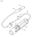
- a tube 90 is coupled to a liquid medicine injection apparatus 60.
- the liquid medicine injection apparatus 60 generally comprises a supply cylinder 64 and a piston 66.
- the piston is moved and pushes out the medicine within the cylinder while being subjected to a force by means of the elasticity of a rubber bladder, gas pressure, a push rod driven by a motor, or the like.
- the tube 90 is connected to an end of the cylinder 64 of the injection apparatus 60.
- a passage for liquid medicine defined by the tube 90 is equipped with, for example, a supply valve 70 for supplying the medicine into the cylinder 64 before using the apparatus.
- a clamp 72 is also provided to cut off a stream of medicine flowing along the tube 90 if necessary.
- the structure of the tube connected to the injection apparatus may be that disclosed in PCT Publication No. WO 02/11791 A1 .
- a distal end connection member 80 and a cap 10 for plugging an opening of the connection member 80 are connected to a distal end of the tube 90.
- a cylindrical projection 84 is provided at an end of the connection member 80.
- the projection 84 is provided with a communication hole 86.
- the medicine is supplied through the hole 86.
- the connection member 80 is provided with a cylindrical wall 82 surrounding the projection 84.
- Female threads are formed on an inner surface of the cylindrical wall 82 and are to be engaged with male threads on an outward extension 261 of the cap 10 to be described later. After the cap 10 is removed, the female threads are threadably engaged with a connector of a catheter or the like.
- the threadably engaged portions are configured to be hermetically sealed.
- the cap 10 substantially takes the shape of a cylinder and has one end connected to the connection member 80 at the distal end of the tube 90.
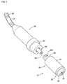
- the cap 10 comprises a main body 20 and a closure 30.
- the main body 20 takes the shape of a stepped hollow cylinder and has a cylindrical outer sidewall 22 extending to an end wall 24. An end of the main body opposite to the end wall is open and is closed with the closure 30 to be described later.
- connection tube 26 formed to axially extend in opposite directions with respect to the end wall 24 is provided at the center on the side of the end wall 24.
- the male threads are formed at a tip portion of the outward extension 261 of the connection tube 26 and are to be engaged with the female threads formed on the inner surface of the cylindrical wall 82 of the connection member 80.
- the connection tube 26 is hollowed to form a passage 263 with a circular cross section.
- the corresponding projection 84 of the connection member 80 is inserted into the passage 263 so that the hole 86 of the projection 84 can be in communication with the passage 263 of the connection tube 26.
- the passage 263 of the connection tube 26 is slightly tapered such that the diameter thereof decreases inward.
- connection tube 26 that is formed to extend inward is spaced apart by a predetermined distance from the sidewall 22.
- a liquid absorption member 40 to be described later is tightly fitted into a space between the inward extension 262 and the sidewall 22.
- the absorption member 40 is a cylindrical member provided with a passage penetrating therethrough at the center thereof, i.e. an annular cylindrical member.
- the absorption member 40 is preferably made of a material that can absorb and hold a liquid well.
- Sponge that is a foam material, and fiber materials such as cloth may be used.
- a sponge made of melamine formaldehyde polycondensate may be used.
- the material of the absorption member in the present invention is not limited thereto. Any material that can absorb liquid well may be used.
- the absorption member 40 has inner and outer diameters such that it can be tightly fitted between an inner surface of the sidewall 22 and an outer surface of the inward extension 262 of the connection tube 26.
- An outer surface of the absorption member 40 is in contact with the sidewall 22 of the main body 20.
- One end of the absorption member is fixedly fitted into an annular space between the inward extension 262 of the connection tube 26 and the sidewall 22 of the main body 20.
- the other end of the absorption member is supported by the closure 30 to be described later.
- the closure 30 comprises a circular lid 32 for covering the opening of the main body 20, and an insertion boss 34 that extends from the lid 32 and is fitted into and contained in the main body 20.
- the lid 32 and the insertion boss 34 are provided with an axial passage 341.
- An end of the axial passage 341 on the side of the lid is provided with a catching step 3431.
- the passage 341 is formed with a tapered portion 342 which is tapered such that the diameter thereof gradually decreases from an end of the insertion boss 34 approximately to the middle of the passage toward the lid 32, and a filter-receiving portion 343 having a substantially constant diameter slightly larger than that of the tapered portion 342 and extending from the tapered portion 342 to an air exhaust hole 321.
- the insertion boss 34 comprises first to third extensions 35, 36 and 37 that are circular in cross section and have outer diameters sequentially decreased toward the end of the insertion boss.
- the outer diameter of the first extension 35 is determined to be in close contact with the inner surface of the sidewall 22 of the main body 20. This is to cause the insertion boss to be tightly fitted and prevent it from escaping when the closure 30 is fitted through the opening of the main body 20.
- the closure 30 may be coupled to the main body 20 by means of an adhesive so that they cannot be separated from each other.
- the second extension 36 has a diameter smaller than that of the first extension 35. There is a step between the first and second extensions 35 and 36.
- the outer diameter of the third extension 37 which is smaller than that of the second extension 36, is determined such that the third extension can be tightly fitted into the liquid absorption member 40.
- the third extension 37 is inserted lengthwise into the liquid absorption member 40.
- An outer surface of the third extension 37 is in close contact with an inner surface of the absorption member 40, and the end of the absorption member 40 abuts on the step between the second and third extensions 36 and 37.
- a distal end of the third extension 37 is tapered so that it can be smoothly inserted into the absorption member 40.
- the third extension 37 functions to prevent the liquid absorption member 40 from abutting on the air pass filter 50 or to prevent liquid absorbed by the liquid absorption member 40 from abutting on the air pass filter 50 due to outflow of the absorbed liquid. If the liquid abuts on the air pass filter 50 or air exhaust hole 321, air cannot be properly exhausted or it takes a great deal of time to exhaust the air.
- the air pass filter 50 is made of a liquid impermeable and gas permeable material and completely closes up the passage 321. That is, the air pass filter is made of a material through which liquid cannot permeate but gas can permeate.
- the air pass filter 50 can be made and used by processing a porous plastic resin material having such a property into a shape suitable for the passage.
- a material for the air pass filter is available from Porex Corporation (website: www.porex.com) located at Fairburn, GA 30213, U.S.A.
- the product under the trademark "Porex Hydrophobic Vents" available from Porex Corporation may be used. This product is made of polyethyl polytetrafluoroethylene.
- the material for the air pass filter is also available from Micropore Plastics, Inc. located at Stone Mountain, Georgia, U.S.A.
- the air pass filter 50 has such elasticity that it can be slightly shrunken while being fitted into the passage 321 of the closure 30 and then can be restored to its original state in place.
- air 91 exists just behind a portion of liquid medicine, which has first reached the end of the tube, within the tube 90.
- the portion of liquid medicine is introduced into the cap 10 through the communication hole 86 of the connection member 80.
- the first introduced portion of liquid medicine is completely absorbed by the liquid absorption member 40 having liquid absorbency before it abuts on the air pass filter 50.
- the portion of liquid medicine that has already been absorbed by the absorption member 40 is prevented from again flowing into the air pass filter 50 by means of the third extension 37 of the closure 30.
- the subsequently introduced air 91 reaches the air pass filter 50 and then naturally and completely escapes to the outside through the liquid impermeable and gas permeable air pass filter 50 and the air exhaust hole 321. Consequently, only liquid medicine remains within the cap 10. Then, the cap 10 is rotated to be separated from the distal end of the connection member 80 and connected to a catheter or the like, so that only the liquid medicine with air completely removed therefrom can be supplied.
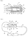
- FIG 4 shows a cap with a string 150 added thereto.
- the string 150 connects the cap 10 to an elemental member of an injection quantity adjustor.
- a case 110 of the injection quantity adjustor 100 is partially cut away to show the interior of the injection quantity adjustor 100.
- the distal end cap 10 is installed at the distal end of the tube 90 connected to the injection quantity adjustor 100.
- the liquid medicine is supplied through the injection quantity adjustor 100 and the tube 90.
- the injection quantity adjustor 100 performs the function of constantly maintaining the amount of supplied liquid medicine and also performs the function of temporarily increasing the amount of supplied liquid medicine.
- the injection quantity adjustor 100 comprises a temporary storage bladder 130 for storing the liquid medicine, a button member 120 for pressing the storage bladder 130, and a clip 140 fitted to maintain a state where the button member 120 presses the storage bladder 130.
- the storage bladder 130 is connected to tubes 131 and 132 through which the liquid medicine flows in and out of the storage bladder.
- the tube 132 through which the liquid medicine flows out can be blocked by means of a shutter 123 of the button member 120 to be described later.
- the temporary storage bladder 130 is to temporarily increase the amount of supplied liquid medicine.
- the liquid medicine is normally supplied through another passage (not shown).
- the button member 120 includes a rotational shaft 121 around which a torsion spring 122 is fitted. Therefore, the button member 120 can be rotated about the rotational shaft 121 and is subjected to the force of the torsion spring 122 exerted in a direction for maintaining the state where the shutter 123 blocks the tube 132.
- a pressing portion 124 and the shutter 123 are provided at opposite sides of the button member 120 with respect to the rotational shaft 121, there are provided a pressing portion 124 and the shutter 123, respectively.
- the pressing portion 124 presses down and squeezes the storage bladder 130, and the shutter 123 that has blocked the tube 132 is raised to open the tube 132, as shown in the figure.
- the liquid medicine stored in the storage bladder 130 is additionally supplied to temporarily increase the amount of supplied liquid medicine.
- a preparatory operation for sending the liquid medicine to the distal end of the tube 90 before the use thereof is made in a state where the storage bladder 130 has been pressed down.
- the clip 140 is fitted above the portion of the button member 120 on the side of the pressing portion 124 in order to maintain the state where the pressing portion 124 presses down the storage bladder 130 as shown in the figure.
- the storage bladder 130 is pressed by the pressing portion 124, and the tube 132, which is connected to the storage bladder 130 and through which the liquid medicine flows out, is in an opened state.
- the liquid medicine flows into the connection member 80 through the injection quantity adjustor 100 and the tube 90.
Landscapes
- Health & Medical Sciences (AREA)
- Heart & Thoracic Surgery (AREA)
- Hematology (AREA)
- Engineering & Computer Science (AREA)
- Anesthesiology (AREA)
- Biomedical Technology (AREA)
- Life Sciences & Earth Sciences (AREA)
- Animal Behavior & Ethology (AREA)
- General Health & Medical Sciences (AREA)
- Public Health (AREA)
- Veterinary Medicine (AREA)
- Pulmonology (AREA)
- Emergency Medicine (AREA)
- Vascular Medicine (AREA)
- Infusion, Injection, And Reservoir Apparatuses (AREA)
Claims (9)
- Kappe (10) für einen Schlauch (90), wobei die Kappe (10) an ein distales Ende des Schlauches (90) angeschlossen ist, welche aufweist:einen Durchlass (263), um mit dem Schlauch (90) und der Außenseite in Verbindung zu sein;ein Absorptionsglied (40) für Flüssigkeit, welches in dem Durchlass (263) angeordnet ist; undein Filter (50), welches für Gas durchlässig und für Flüssigkeit undurchlässig ist, um den Durchlass (263) bei einer Position zu blockieren, welche weiter weg als das Absorptionsglied (40) für Flüssigkeit von dem Schlauch (90) liegt;dadurch gekennzeichnet, dass das Absorptionsglied für Flüssigkeit den Durchlass umgibt.
- Kappe (10) nach Anspruch 1, wobei das Absorptionsglied (40) für Flüssigkeit aus einem Schwammmaterial hergestellt ist.
- Kappe (10) nach Anspruch 1, wobei das Absorptionsglied (40) für Flüssigkeit aus einem Fasermaterial hergestellt ist.
- Kappe (10) nach Anspruch 1, wobei das Filter (50) aus einem porösen Kunststoffharzmaterial hergestellt ist.
- Kappe (10) nach einem der Ansprüche 1 bis 4, welche ferner aufweist:ein Hauptteil (20), welches eine äußere Wand (22) und eine Verbindungsausladung aufweist, welche radial innerhalb der äußeren Wand (22) vorgesehen ist, und in welcher das andere Ende, welches einem Ende des Hauptteils (20) gegenüberliegt, bei welchem die Verbindungsausladung, welche auf ihm vorgesehen ist, offen ist, und der Durchlass (263) gebildet ist und das Absorptionsglied (40) für Flüssigkeit aufgenommen ist; undeinen Abschluss (30), welcher angeschlossen ist, um das andere offene Ende des Hauptteils (20) abzuschließen und welcher ein Entlüftungsloch (321) beinhaltet, das mit dem Durchlass (263) in Verbindung ist und durch das Filter (50) blockiert ist.
- Kappe (10) nach Anspruch 5, wobei die Verbindungsausladung einen Schlauch (26) aufweist, welcher sich nach innen und nach außen vom Ende der äußeren Wand (22) erstreckt und das Absorptionsglied (40) zwischen der äußeren Wand (22) des Hauptteils (20) und einem nach innen gerichteten Ansatzstück (262) der Verbindungsausladung fest angebracht ist.
- Kappe (10) nach Anspruch 5, wobei der Abschluss (30) ferner ein Ansatzstück (37) aufweist, um das Absorptionsglied (40) und das Filter (50) voneinander zu isolieren.
- Zuführgerät (60) für eine flüssige Medizin, um eine flüssige Medizin zu liefern, welches aufweist:ein Reservoir bzw. einen Vorratsbehälter (64) für eine flüssige Medizin;eine Druckvorrichtung (66), um Druck auf die flüssige Medizin auszuüben, welche in dem Reservoir (64) für flüssige Medizin gespeichert ist,einen Schlauch (90), welcher mit dem Reservoir (64) für flüssige Medizin verbunden ist; undeine Kappe (10) entsprechend einem der Ansprüche 1 bis 7, welche mit dem distalen Ende des Schlauches (90) verbunden ist.
- Gerät (60), wie in Anspruch 8 beansprucht, welches eine Strömungssteuereinrichtung (100) aufweist, welche ein Glied bzw. Teil (140) aufweist, welches an die Kappe (10) angeschlossen ist und welches beim Zuführen der flüssigen Medizin zu entfernen ist.
Applications Claiming Priority (5)
| Application Number | Priority Date | Filing Date | Title |
|---|---|---|---|
| KR20020047128 | 2002-08-09 | ||
| KR2002047128 | 2002-08-09 | ||
| KR2002073983 | 2002-11-26 | ||
| KR10-2002-0073983A KR100463636B1 (ko) | 2002-08-09 | 2002-11-26 | 액체 주입용 튜브의 캡 |
| PCT/KR2003/001580 WO2004014477A1 (en) | 2002-08-09 | 2003-08-06 | Cap of tube for supplying liquid |
Publications (3)
| Publication Number | Publication Date |
|---|---|
| EP1534379A1 EP1534379A1 (de) | 2005-06-01 |
| EP1534379A4 EP1534379A4 (de) | 2007-09-19 |
| EP1534379B1 true EP1534379B1 (de) | 2008-12-03 |
Family
ID=31719944
Family Applications (1)
| Application Number | Title | Priority Date | Filing Date |
|---|---|---|---|
| EP03784671A Expired - Lifetime EP1534379B1 (de) | 2002-08-09 | 2003-08-06 | Kappe für einen schlauch zur abgabe von flüssigkeit |
Country Status (5)
| Country | Link |
|---|---|
| US (1) | US7431712B2 (de) |
| EP (1) | EP1534379B1 (de) |
| JP (1) | JP4295217B2 (de) |
| AU (1) | AU2003252546B2 (de) |
| WO (1) | WO2004014477A1 (de) |
Cited By (1)
| Publication number | Priority date | Publication date | Assignee | Title |
|---|---|---|---|---|
| DE102007060131A1 (de) * | 2007-12-13 | 2009-06-25 | Technische Universität Dresden | Verfahren und Vorrichtung zum luftfreien Befüllen von Gefäßanschlüssen im Medizinbereich |
Families Citing this family (60)
| Publication number | Priority date | Publication date | Assignee | Title |
|---|---|---|---|---|
| US7766897B2 (en) * | 2006-01-02 | 2010-08-03 | Carefusion 303, Inc. | Protective priming cap for self-sealing male Luer valve |
| JP5161457B2 (ja) * | 2006-04-03 | 2013-03-13 | 日本コヴィディエン株式会社 | 雄ルアーコネクター |
| US9700710B2 (en) | 2006-06-22 | 2017-07-11 | Excelsior Medical Corporation | Antiseptic cap equipped syringe |
| US11229746B2 (en) | 2006-06-22 | 2022-01-25 | Excelsior Medical Corporation | Antiseptic cap |
| US9259535B2 (en) | 2006-06-22 | 2016-02-16 | Excelsior Medical Corporation | Antiseptic cap equipped syringe |
| US8167847B2 (en) * | 2006-06-22 | 2012-05-01 | Excelsior Medical Corporation | Antiseptic cap and antiseptic cap equipped plunger and syringe barrel assembly |
| US8343112B2 (en) * | 2009-10-30 | 2013-01-01 | Catheter Connections, Inc. | Disinfecting caps having an extendable feature and related systems and methods |
| US8172825B2 (en) * | 2007-01-16 | 2012-05-08 | The University Of Utah Research Foundation | Methods for disinfecting medical connectors |
| US8647326B2 (en) * | 2007-01-16 | 2014-02-11 | Catheter Connections, Inc. | System for cleaning luer connectors |
| US8419713B1 (en) | 2012-08-01 | 2013-04-16 | The University Of Utah Research Foundation | Carrier assembly with caps for medical connectors |
| US8177761B2 (en) * | 2007-01-16 | 2012-05-15 | The University Of Utah Research Foundation | Assembly for cleaning luer connectors |
| US8197749B2 (en) | 2007-01-16 | 2012-06-12 | The University Of Utah Research Foundation | Methods for cleaning luer connectors |
| US8328767B2 (en) | 2007-01-16 | 2012-12-11 | Catheter Connections, Inc. | Disinfecting caps for medical male luer connectors |
| US8523830B2 (en) * | 2007-01-16 | 2013-09-03 | Catheter Connections | Disinfecting caps for medical female luer connectors |
| US8523831B2 (en) * | 2009-10-30 | 2013-09-03 | Catheter Connections, Inc. | Disinfecting caps having sealing features and related systems and methods |
| JP4886535B2 (ja) * | 2007-01-30 | 2012-02-29 | 日本コヴィディエン株式会社 | コネクター用キャップ |
| US9192449B2 (en) | 2007-04-02 | 2015-11-24 | C. R. Bard, Inc. | Medical component scrubbing device with detachable cap |
| US8336152B2 (en) | 2007-04-02 | 2012-12-25 | C. R. Bard, Inc. | Insert for a microbial scrubbing device |
| JP5154326B2 (ja) * | 2008-07-28 | 2013-02-27 | 日本コヴィディエン株式会社 | キャップ付き医療用活栓 |
| US9078992B2 (en) | 2008-10-27 | 2015-07-14 | Pursuit Vascular, Inc. | Medical device for applying antimicrobial to proximal end of catheter |
| USD695398S1 (en) | 2009-10-30 | 2013-12-10 | Catheter Connections, Inc. | Cap for use with one or more medical connectors |
| CA2995411C (en) * | 2009-10-30 | 2021-09-28 | Merit Medical Systems, Inc. | Disinfecting caps and systems and associated methods |
| US20110238018A1 (en) * | 2010-03-24 | 2011-09-29 | Mckenzie-Butler Karen | Intravenous Line Preparation Device |
| JP5804675B2 (ja) * | 2010-05-27 | 2015-11-04 | 日本コヴィディエン株式会社 | コネクター用キャップ及びこれを備えた輸液ラインの接続装置 |
| WO2012162259A2 (en) | 2011-05-20 | 2012-11-29 | Excelsior Medical Corporation | Caps for cannula access devices |
| US9867975B2 (en) * | 2011-05-23 | 2018-01-16 | Excelsior Medical Corporation | Antiseptic line cap |
| US10166381B2 (en) | 2011-05-23 | 2019-01-01 | Excelsior Medical Corporation | Antiseptic cap |
| EP3714932A1 (de) | 2011-07-12 | 2020-09-30 | ICU Medical, Inc. | Vorrichtung zur verabreichung eines antimikrobiellen mittels in einen transdermalen katheter |
| DE102012022261A1 (de) | 2012-11-13 | 2014-05-15 | Robert Simmoteit | Kappe und Vorrichtung |
| US9314607B2 (en) * | 2013-03-20 | 2016-04-19 | Swi Barak | Vented Luer tip connector |
| USD780913S1 (en) * | 2013-07-25 | 2017-03-07 | Nipro Corporation | Syringe barrel |
| USD755957S1 (en) * | 2013-12-13 | 2016-05-10 | Bryan Larson | Dental carpule |
| BR112016016759B1 (pt) | 2014-01-31 | 2021-02-02 | Industrie Borla S.P.A | conector luer macho valvulado |
| WO2015168677A1 (en) | 2014-05-02 | 2015-11-05 | Excelsior Medical Corporation | Strip package for antiseptic cap |
| US11628288B1 (en) | 2014-07-14 | 2023-04-18 | Merit Medical Systems, Inc. | Disinfecting cap for needleless injection sites |
| EP3194012A4 (de) | 2014-09-19 | 2018-09-12 | Children's Medical Center Corporation | Vorrichtungen zum reinigen von katheteranschlüssen |
| WO2016085815A1 (en) | 2014-11-24 | 2016-06-02 | Catheter Connections, Inc. | Disinfecting cap for medical connectors |
| EP3258987B1 (de) * | 2015-02-19 | 2018-09-26 | UMC Utrecht Holding B.V. | Vorrichtung zur verabreichung von flüssigen medikamenten |
| CA2982456A1 (en) | 2015-05-08 | 2016-11-17 | Icu Medical, Inc. | Medical connectors configured to receive emitters of therapeutic agents |
| EP3377420A4 (de) | 2015-11-16 | 2019-07-10 | Merit Medical Systems, Inc. | Desinfektionskappe für luer-anschlüsse |
| AU2017341782B2 (en) | 2016-10-14 | 2023-03-16 | Icu Medical, Inc. | Sanitizing caps for medical connectors |
| EP3570810B1 (de) * | 2017-01-17 | 2025-09-24 | Becton Dickinson and Company Limited | Spritzenadapter mit kappe |
| EP3573699B1 (de) | 2017-01-27 | 2022-08-10 | Merit Medical Systems, Inc. | Desinfizierende luer-kappe und verfahren zur verwendung |
| WO2018204206A2 (en) | 2017-05-01 | 2018-11-08 | Icu Medical, Inc. | Medical fluid connectors and methods for providing additives in medical fluid lines |
| WO2019070878A1 (en) | 2017-10-04 | 2019-04-11 | Merit Medical Systems, Inc. | DISINFECTANT CAP FOR VALVE CONNECTORS AND METHOD OF USE |
| USD877897S1 (en) * | 2017-12-29 | 2020-03-10 | Ge Healthcare Bio-Sciences Corp. | Probe sheath |
| USD845472S1 (en) * | 2018-03-26 | 2019-04-09 | Richard O. Evans | Medicine vial protector |
| KR102137838B1 (ko) * | 2018-04-27 | 2020-07-24 | 주식회사 이화메디텍 | 약액주입용 튜브의 엔드캡 |
| KR102192985B1 (ko) * | 2018-08-01 | 2020-12-18 | 김용현 | 약액 주입 장치용 엔드 캡 및 약액 주입 장치 세트 |
| US11541221B2 (en) | 2018-11-07 | 2023-01-03 | Icu Medical, Inc. | Tubing set with antimicrobial properties |
| US11400195B2 (en) | 2018-11-07 | 2022-08-02 | Icu Medical, Inc. | Peritoneal dialysis transfer set with antimicrobial properties |
| US11541220B2 (en) | 2018-11-07 | 2023-01-03 | Icu Medical, Inc. | Needleless connector with antimicrobial properties |
| US11534595B2 (en) | 2018-11-07 | 2022-12-27 | Icu Medical, Inc. | Device for delivering an antimicrobial composition into an infusion device |
| US11517732B2 (en) | 2018-11-07 | 2022-12-06 | Icu Medical, Inc. | Syringe with antimicrobial properties |
| US11433215B2 (en) | 2018-11-21 | 2022-09-06 | Icu Medical, Inc. | Antimicrobial device comprising a cap with ring and insert |
| DE102019204211A1 (de) * | 2019-03-27 | 2020-10-01 | B. Braun Melsungen Aktiengesellschaft | Medizinischer Fluidkonnektor |
| US20210186394A1 (en) * | 2019-12-20 | 2021-06-24 | Becton, Dickinson And Company | Catheter extension set and related methods |
| US12544551B2 (en) * | 2020-04-23 | 2026-02-10 | Otsuka Techno Corporation | Urinary catheter cap |
| EP4255552A1 (de) | 2020-12-07 | 2023-10-11 | ICU Medical, Inc. | Peritonealdialysekappen, systeme und verfahren |
| US20220203046A1 (en) * | 2020-12-31 | 2022-06-30 | Carefusion 303, Inc. | Auto priming vent plug |
Family Cites Families (22)
| Publication number | Priority date | Publication date | Assignee | Title |
|---|---|---|---|---|
| US3631654A (en) * | 1968-10-03 | 1972-01-04 | Pall Corp | Gas purge device |
| US3830241A (en) * | 1972-08-07 | 1974-08-20 | Kendall & Co | Vented adapter |
| US3906958A (en) * | 1974-06-21 | 1975-09-23 | Abbott Lab | Catheter adapter having filtered air vent |
| DE3147499A1 (de) | 1981-12-01 | 1983-06-09 | B. Braun Melsungen Ag, 3508 Melsungen | "entlueftungseinrichtung fuer ein medizinisches fluessigkeitssystem" |
| US4445896A (en) | 1982-03-18 | 1984-05-01 | Cook, Inc. | Catheter plug |
| US4597758A (en) * | 1982-09-21 | 1986-07-01 | Baxter Travenol Laboratories, Inc. | Sealing closure for a Luer fitting in open communication with a pressurized liquid supply |
| US4571244A (en) * | 1984-05-07 | 1986-02-18 | Biogenesis, Inc. | System for removing gas bubbles from liquids |
| US4596557A (en) | 1984-06-26 | 1986-06-24 | Pexa Charles E | Air eliminator for intravenous tube |
| US4624664A (en) | 1985-07-22 | 1986-11-25 | Travenol European Research And Development Centre (Teradec) | Antibacterial closure system |
| DE3832028A1 (de) * | 1988-09-21 | 1990-03-22 | Minh Bach Dr Ing Dr Med Quang | Vorrichtung zum entlueften von in medizinischen fluessigkeitssystemen stroemenden fluessigkeiten |
| JPH07106220B2 (ja) * | 1989-06-09 | 1995-11-15 | テルモ株式会社 | 医療用具コネクター用キャップ |
| US5131387A (en) * | 1990-05-09 | 1992-07-21 | Marquette Gas Analysis Corp. | Moisture trap |
| US5125415A (en) * | 1990-06-19 | 1992-06-30 | Smiths Industries Medical Systems, Inc. | Syringe tip cap with self-sealing filter |
| US5348570A (en) * | 1993-04-05 | 1994-09-20 | Rockwell International Corporation | Axle housing breather |
| US6196998B1 (en) * | 1994-12-12 | 2001-03-06 | Becton Dickinson And Company | Syringe and tip cap assembly |
| US5674200A (en) * | 1996-02-05 | 1997-10-07 | Filtertek Inc. | Air eliminator |
| US5779674A (en) * | 1996-05-06 | 1998-07-14 | Mallinckrodt Medical, Inc. | Fluid gas removal drip chamber |
| US6013061A (en) * | 1997-10-15 | 2000-01-11 | Microwave Medical Systems, Inc. | Automatic air eliminator |
| EP1042029B1 (de) * | 1997-12-22 | 2015-09-16 | Celgard, LLC | Vorrichtung zum Entfernen von Gasblasen und gelösten Gasen aus Flüssigkeiten |
| AU2001222342A1 (en) * | 2000-07-22 | 2002-02-18 | Yong-Nyun Kim | Liquid supply apparatus |
| KR200226997Y1 (ko) * | 2000-10-27 | 2001-06-15 | 유재구 | 낚시줄 엉킴 및 풀림 방지용 스풀 |
| US20050124935A1 (en) * | 2003-12-05 | 2005-06-09 | Kimberly-Clark Worldwide, Inc. | Venting adapter for feeding device |
-
2003
- 2003-08-06 EP EP03784671A patent/EP1534379B1/de not_active Expired - Lifetime
- 2003-08-06 WO PCT/KR2003/001580 patent/WO2004014477A1/en not_active Ceased
- 2003-08-06 US US10/523,993 patent/US7431712B2/en not_active Expired - Lifetime
- 2003-08-06 AU AU2003252546A patent/AU2003252546B2/en not_active Ceased
- 2003-08-06 JP JP2004527428A patent/JP4295217B2/ja not_active Expired - Lifetime
Cited By (1)
| Publication number | Priority date | Publication date | Assignee | Title |
|---|---|---|---|---|
| DE102007060131A1 (de) * | 2007-12-13 | 2009-06-25 | Technische Universität Dresden | Verfahren und Vorrichtung zum luftfreien Befüllen von Gefäßanschlüssen im Medizinbereich |
Also Published As
| Publication number | Publication date |
|---|---|
| JP4295217B2 (ja) | 2009-07-15 |
| EP1534379A4 (de) | 2007-09-19 |
| EP1534379A1 (de) | 2005-06-01 |
| JP2005535379A (ja) | 2005-11-24 |
| US20050203460A1 (en) | 2005-09-15 |
| AU2003252546A1 (en) | 2004-02-25 |
| US7431712B2 (en) | 2008-10-07 |
| AU2003252546B2 (en) | 2007-01-25 |
| WO2004014477A1 (en) | 2004-02-19 |
Similar Documents
| Publication | Publication Date | Title |
|---|---|---|
| EP1534379B1 (de) | Kappe für einen schlauch zur abgabe von flüssigkeit | |
| CN115916313B (zh) | 用于导管的润湿机构 | |
| AU641838B2 (en) | Piercing needle | |
| EP4295887A2 (de) | Benetzungsmechanismus für einen katheter | |
| EP0827414B1 (de) | Behandlungsmittelbehälter für ein saugdrainagesystem | |
| US6780309B2 (en) | Tapered hydrophobic filter for suction canisters | |
| JP3673297B2 (ja) | 採血装置 | |
| JP2023522428A (ja) | カテーテルの湿潤機構 | |
| JP2005349195A (ja) | 通気機構付き採血セット | |
| US7267653B2 (en) | Blood collection needle | |
| CN100536956C (zh) | 用于供应液体的管的帽 | |
| JP3674946B2 (ja) | 採血針 | |
| JP3610568B2 (ja) | 採血針 | |
| JP3723972B2 (ja) | 採血針 | |
| RU2248816C2 (ru) | Кожный аппликатор жидкости | |
| HK1084613B (en) | Cap of tube for supplying liquid | |
| JP2771291B2 (ja) | 可撓性チューブのキャップ | |
| GB2077611A (en) | Partially flexible fluid filter assembly | |
| JP3027007U (ja) | 空気抜きの容易な浮き袋類 | |
| JP2002253640A (ja) | 空気供給部を備えた医療用具 |
Legal Events
| Date | Code | Title | Description |
|---|---|---|---|
| PUAI | Public reference made under article 153(3) epc to a published international application that has entered the european phase |
Free format text: ORIGINAL CODE: 0009012 |
|
| 17P | Request for examination filed |
Effective date: 20050309 |
|
| AK | Designated contracting states |
Kind code of ref document: A1 Designated state(s): AT BE BG CH CY CZ DE DK EE ES FI FR GB GR HU IE IT LI LU MC NL PT RO SE SI SK TR |
|
| AX | Request for extension of the european patent |
Extension state: AL LT LV MK |
|
| DAX | Request for extension of the european patent (deleted) | ||
| RAP1 | Party data changed (applicant data changed or rights of an application transferred) |
Owner name: E-WHA FRESENIUS KABI INC. |
|
| RIN1 | Information on inventor provided before grant (corrected) |
Inventor name: KIM, YONG-NYUN |
|
| RIN1 | Information on inventor provided before grant (corrected) |
Inventor name: KIM, YONG-NYUN |
|
| A4 | Supplementary search report drawn up and despatched |
Effective date: 20070817 |
|
| RIC1 | Information provided on ipc code assigned before grant |
Ipc: A61M 39/20 20060101AFI20040302BHEP Ipc: B65D 51/16 20060101ALI20070810BHEP |
|
| 17Q | First examination report despatched |
Effective date: 20071106 |
|
| GRAP | Despatch of communication of intention to grant a patent |
Free format text: ORIGINAL CODE: EPIDOSNIGR1 |
|
| GRAS | Grant fee paid |
Free format text: ORIGINAL CODE: EPIDOSNIGR3 |
|
| GRAA | (expected) grant |
Free format text: ORIGINAL CODE: 0009210 |
|
| AK | Designated contracting states |
Kind code of ref document: B1 Designated state(s): AT BE BG CH CY CZ DE DK EE ES FI FR GB GR HU IE IT LI LU MC NL PT RO SE SI SK TR |
|
| REG | Reference to a national code |
Ref country code: GB Ref legal event code: FG4D |
|
| REG | Reference to a national code |
Ref country code: CH Ref legal event code: EP |
|
| REG | Reference to a national code |
Ref country code: IE Ref legal event code: FG4D |
|
| REF | Corresponds to: |
Ref document number: 60325069 Country of ref document: DE Date of ref document: 20090115 Kind code of ref document: P |
|
| REG | Reference to a national code |
Ref country code: CH Ref legal event code: NV Representative=s name: HEPP WENGER RYFFEL AG |
|
| PG25 | Lapsed in a contracting state [announced via postgrant information from national office to epo] |
Ref country code: ES Free format text: LAPSE BECAUSE OF FAILURE TO SUBMIT A TRANSLATION OF THE DESCRIPTION OR TO PAY THE FEE WITHIN THE PRESCRIBED TIME-LIMIT Effective date: 20090314 |
|
| NLV1 | Nl: lapsed or annulled due to failure to fulfill the requirements of art. 29p and 29m of the patents act | ||
| PG25 | Lapsed in a contracting state [announced via postgrant information from national office to epo] |
Ref country code: SI Free format text: LAPSE BECAUSE OF FAILURE TO SUBMIT A TRANSLATION OF THE DESCRIPTION OR TO PAY THE FEE WITHIN THE PRESCRIBED TIME-LIMIT Effective date: 20081203 Ref country code: FI Free format text: LAPSE BECAUSE OF FAILURE TO SUBMIT A TRANSLATION OF THE DESCRIPTION OR TO PAY THE FEE WITHIN THE PRESCRIBED TIME-LIMIT Effective date: 20081203 Ref country code: NL Free format text: LAPSE BECAUSE OF FAILURE TO SUBMIT A TRANSLATION OF THE DESCRIPTION OR TO PAY THE FEE WITHIN THE PRESCRIBED TIME-LIMIT Effective date: 20081203 |
|
| PG25 | Lapsed in a contracting state [announced via postgrant information from national office to epo] |
Ref country code: EE Free format text: LAPSE BECAUSE OF FAILURE TO SUBMIT A TRANSLATION OF THE DESCRIPTION OR TO PAY THE FEE WITHIN THE PRESCRIBED TIME-LIMIT Effective date: 20081203 Ref country code: BG Free format text: LAPSE BECAUSE OF FAILURE TO SUBMIT A TRANSLATION OF THE DESCRIPTION OR TO PAY THE FEE WITHIN THE PRESCRIBED TIME-LIMIT Effective date: 20090303 Ref country code: RO Free format text: LAPSE BECAUSE OF FAILURE TO SUBMIT A TRANSLATION OF THE DESCRIPTION OR TO PAY THE FEE WITHIN THE PRESCRIBED TIME-LIMIT Effective date: 20081203 Ref country code: BE Free format text: LAPSE BECAUSE OF FAILURE TO SUBMIT A TRANSLATION OF THE DESCRIPTION OR TO PAY THE FEE WITHIN THE PRESCRIBED TIME-LIMIT Effective date: 20081203 |
|
| PG25 | Lapsed in a contracting state [announced via postgrant information from national office to epo] |
Ref country code: PT Free format text: LAPSE BECAUSE OF FAILURE TO SUBMIT A TRANSLATION OF THE DESCRIPTION OR TO PAY THE FEE WITHIN THE PRESCRIBED TIME-LIMIT Effective date: 20090504 Ref country code: SE Free format text: LAPSE BECAUSE OF FAILURE TO SUBMIT A TRANSLATION OF THE DESCRIPTION OR TO PAY THE FEE WITHIN THE PRESCRIBED TIME-LIMIT Effective date: 20090303 Ref country code: CZ Free format text: LAPSE BECAUSE OF FAILURE TO SUBMIT A TRANSLATION OF THE DESCRIPTION OR TO PAY THE FEE WITHIN THE PRESCRIBED TIME-LIMIT Effective date: 20081203 Ref country code: AT Free format text: LAPSE BECAUSE OF FAILURE TO SUBMIT A TRANSLATION OF THE DESCRIPTION OR TO PAY THE FEE WITHIN THE PRESCRIBED TIME-LIMIT Effective date: 20081203 |
|
| PG25 | Lapsed in a contracting state [announced via postgrant information from national office to epo] |
Ref country code: SK Free format text: LAPSE BECAUSE OF FAILURE TO SUBMIT A TRANSLATION OF THE DESCRIPTION OR TO PAY THE FEE WITHIN THE PRESCRIBED TIME-LIMIT Effective date: 20081203 |
|
| PLBE | No opposition filed within time limit |
Free format text: ORIGINAL CODE: 0009261 |
|
| STAA | Information on the status of an ep patent application or granted ep patent |
Free format text: STATUS: NO OPPOSITION FILED WITHIN TIME LIMIT |
|
| PG25 | Lapsed in a contracting state [announced via postgrant information from national office to epo] |
Ref country code: DK Free format text: LAPSE BECAUSE OF FAILURE TO SUBMIT A TRANSLATION OF THE DESCRIPTION OR TO PAY THE FEE WITHIN THE PRESCRIBED TIME-LIMIT Effective date: 20081203 |
|
| 26N | No opposition filed |
Effective date: 20090904 |
|
| PG25 | Lapsed in a contracting state [announced via postgrant information from national office to epo] |
Ref country code: MC Free format text: LAPSE BECAUSE OF NON-PAYMENT OF DUE FEES Effective date: 20090831 |
|
| REG | Reference to a national code |
Ref country code: IE Ref legal event code: MM4A |
|
| PG25 | Lapsed in a contracting state [announced via postgrant information from national office to epo] |
Ref country code: IE Free format text: LAPSE BECAUSE OF NON-PAYMENT OF DUE FEES Effective date: 20090806 |
|
| PG25 | Lapsed in a contracting state [announced via postgrant information from national office to epo] |
Ref country code: GR Free format text: LAPSE BECAUSE OF FAILURE TO SUBMIT A TRANSLATION OF THE DESCRIPTION OR TO PAY THE FEE WITHIN THE PRESCRIBED TIME-LIMIT Effective date: 20090304 |
|
| PG25 | Lapsed in a contracting state [announced via postgrant information from national office to epo] |
Ref country code: IT Free format text: LAPSE BECAUSE OF FAILURE TO SUBMIT A TRANSLATION OF THE DESCRIPTION OR TO PAY THE FEE WITHIN THE PRESCRIBED TIME-LIMIT Effective date: 20081203 |
|
| PG25 | Lapsed in a contracting state [announced via postgrant information from national office to epo] |
Ref country code: LU Free format text: LAPSE BECAUSE OF NON-PAYMENT OF DUE FEES Effective date: 20090806 |
|
| PG25 | Lapsed in a contracting state [announced via postgrant information from national office to epo] |
Ref country code: HU Free format text: LAPSE BECAUSE OF FAILURE TO SUBMIT A TRANSLATION OF THE DESCRIPTION OR TO PAY THE FEE WITHIN THE PRESCRIBED TIME-LIMIT Effective date: 20090604 |
|
| PG25 | Lapsed in a contracting state [announced via postgrant information from national office to epo] |
Ref country code: TR Free format text: LAPSE BECAUSE OF FAILURE TO SUBMIT A TRANSLATION OF THE DESCRIPTION OR TO PAY THE FEE WITHIN THE PRESCRIBED TIME-LIMIT Effective date: 20081203 |
|
| PG25 | Lapsed in a contracting state [announced via postgrant information from national office to epo] |
Ref country code: CY Free format text: LAPSE BECAUSE OF FAILURE TO SUBMIT A TRANSLATION OF THE DESCRIPTION OR TO PAY THE FEE WITHIN THE PRESCRIBED TIME-LIMIT Effective date: 20081203 |
|
| REG | Reference to a national code |
Ref country code: FR Ref legal event code: PLFP Year of fee payment: 14 |
|
| REG | Reference to a national code |
Ref country code: FR Ref legal event code: PLFP Year of fee payment: 15 |
|
| REG | Reference to a national code |
Ref country code: FR Ref legal event code: PLFP Year of fee payment: 16 |
|
| PGFP | Annual fee paid to national office [announced via postgrant information from national office to epo] |
Ref country code: FR Payment date: 20210819 Year of fee payment: 19 |
|
| PGFP | Annual fee paid to national office [announced via postgrant information from national office to epo] |
Ref country code: GB Payment date: 20210820 Year of fee payment: 19 Ref country code: CH Payment date: 20210819 Year of fee payment: 19 Ref country code: DE Payment date: 20210831 Year of fee payment: 19 |
|
| REG | Reference to a national code |
Ref country code: DE Ref legal event code: R119 Ref document number: 60325069 Country of ref document: DE |
|
| REG | Reference to a national code |
Ref country code: CH Ref legal event code: PL |
|
| GBPC | Gb: european patent ceased through non-payment of renewal fee |
Effective date: 20220806 |
|
| PG25 | Lapsed in a contracting state [announced via postgrant information from national office to epo] |
Ref country code: LI Free format text: LAPSE BECAUSE OF NON-PAYMENT OF DUE FEES Effective date: 20220831 Ref country code: CH Free format text: LAPSE BECAUSE OF NON-PAYMENT OF DUE FEES Effective date: 20220831 |
|
| PG25 | Lapsed in a contracting state [announced via postgrant information from national office to epo] |
Ref country code: FR Free format text: LAPSE BECAUSE OF NON-PAYMENT OF DUE FEES Effective date: 20220831 Ref country code: DE Free format text: LAPSE BECAUSE OF NON-PAYMENT OF DUE FEES Effective date: 20230301 |
|
| PG25 | Lapsed in a contracting state [announced via postgrant information from national office to epo] |
Ref country code: GB Free format text: LAPSE BECAUSE OF NON-PAYMENT OF DUE FEES Effective date: 20220806 |