EP1534096B1 - Planar adhesive closure piece - Google Patents
Planar adhesive closure piece Download PDFInfo
- Publication number
- EP1534096B1 EP1534096B1 EP03793616A EP03793616A EP1534096B1 EP 1534096 B1 EP1534096 B1 EP 1534096B1 EP 03793616 A EP03793616 A EP 03793616A EP 03793616 A EP03793616 A EP 03793616A EP 1534096 B1 EP1534096 B1 EP 1534096B1
- Authority
- EP
- European Patent Office
- Prior art keywords
- thread
- threads
- weave
- weft
- adhesive closure
- Prior art date
- Legal status (The legal status is an assumption and is not a legal conclusion. Google has not performed a legal analysis and makes no representation as to the accuracy of the status listed.)
- Expired - Lifetime
Links
- 239000000853 adhesive Substances 0.000 title claims abstract description 36
- 230000001070 adhesive effect Effects 0.000 title claims abstract description 36
- 239000000463 material Substances 0.000 claims description 9
- 239000004033 plastic Substances 0.000 claims description 5
- 239000004677 Nylon Substances 0.000 claims description 2
- 239000004743 Polypropylene Substances 0.000 claims description 2
- 229920001778 nylon Polymers 0.000 claims description 2
- -1 polypropylene Polymers 0.000 claims description 2
- 229920001155 polypropylene Polymers 0.000 claims description 2
- 239000004744 fabric Substances 0.000 abstract description 22
- 238000004519 manufacturing process Methods 0.000 description 7
- 239000000835 fiber Substances 0.000 description 3
- 235000014676 Phragmites communis Nutrition 0.000 description 2
- 230000001419 dependent effect Effects 0.000 description 2
- 230000000694 effects Effects 0.000 description 2
- 238000000926 separation method Methods 0.000 description 2
- 239000004753 textile Substances 0.000 description 2
- 238000009941 weaving Methods 0.000 description 2
- 235000001674 Agaricus brunnescens Nutrition 0.000 description 1
- 229920000914 Metallic fiber Polymers 0.000 description 1
- 239000002390 adhesive tape Substances 0.000 description 1
- 230000000739 chaotic effect Effects 0.000 description 1
- 230000001609 comparable effect Effects 0.000 description 1
- 238000005520 cutting process Methods 0.000 description 1
- 238000010348 incorporation Methods 0.000 description 1
- 239000011159 matrix material Substances 0.000 description 1
- 239000000155 melt Substances 0.000 description 1
- 239000002184 metal Substances 0.000 description 1
Images
Classifications
-
- A—HUMAN NECESSITIES
- A44—HABERDASHERY; JEWELLERY
- A44B—BUTTONS, PINS, BUCKLES, SLIDE FASTENERS, OR THE LIKE
- A44B18/00—Fasteners of the touch-and-close type; Making such fasteners
- A44B18/0069—Details
- A44B18/0092—Details flame retardant
-
- A—HUMAN NECESSITIES
- A44—HABERDASHERY; JEWELLERY
- A44B—BUTTONS, PINS, BUCKLES, SLIDE FASTENERS, OR THE LIKE
- A44B18/00—Fasteners of the touch-and-close type; Making such fasteners
- A44B18/0023—Woven or knitted fasteners
-
- A—HUMAN NECESSITIES
- A44—HABERDASHERY; JEWELLERY
- A44B—BUTTONS, PINS, BUCKLES, SLIDE FASTENERS, OR THE LIKE
- A44B18/00—Fasteners of the touch-and-close type; Making such fasteners
- A44B18/0023—Woven or knitted fasteners
- A44B18/0038—Male or hook elements
- A44B18/0042—Male or hook elements of a mushroom type
-
- Y—GENERAL TAGGING OF NEW TECHNOLOGICAL DEVELOPMENTS; GENERAL TAGGING OF CROSS-SECTIONAL TECHNOLOGIES SPANNING OVER SEVERAL SECTIONS OF THE IPC; TECHNICAL SUBJECTS COVERED BY FORMER USPC CROSS-REFERENCE ART COLLECTIONS [XRACs] AND DIGESTS
- Y10—TECHNICAL SUBJECTS COVERED BY FORMER USPC
- Y10T—TECHNICAL SUBJECTS COVERED BY FORMER US CLASSIFICATION
- Y10T24/00—Buckles, buttons, clasps, etc.
- Y10T24/27—Buckles, buttons, clasps, etc. including readily dissociable fastener having numerous, protruding, unitary filaments randomly interlocking with, and simultaneously moving towards, mating structure [e.g., hook-loop type fastener]
- Y10T24/2733—Buckles, buttons, clasps, etc. including readily dissociable fastener having numerous, protruding, unitary filaments randomly interlocking with, and simultaneously moving towards, mating structure [e.g., hook-loop type fastener] having filaments formed from continuous element interwoven or knitted into distinct, mounting surface fabric
-
- Y—GENERAL TAGGING OF NEW TECHNOLOGICAL DEVELOPMENTS; GENERAL TAGGING OF CROSS-SECTIONAL TECHNOLOGIES SPANNING OVER SEVERAL SECTIONS OF THE IPC; TECHNICAL SUBJECTS COVERED BY FORMER USPC CROSS-REFERENCE ART COLLECTIONS [XRACs] AND DIGESTS
- Y10—TECHNICAL SUBJECTS COVERED BY FORMER USPC
- Y10T—TECHNICAL SUBJECTS COVERED BY FORMER US CLASSIFICATION
- Y10T428/00—Stock material or miscellaneous articles
- Y10T428/23907—Pile or nap type surface or component
- Y10T428/23957—Particular shape or structure of pile
- Y10T428/23964—U-, V-, or W-shaped or continuous strand, filamentary material
-
- Y—GENERAL TAGGING OF NEW TECHNOLOGICAL DEVELOPMENTS; GENERAL TAGGING OF CROSS-SECTIONAL TECHNOLOGIES SPANNING OVER SEVERAL SECTIONS OF THE IPC; TECHNICAL SUBJECTS COVERED BY FORMER USPC CROSS-REFERENCE ART COLLECTIONS [XRACs] AND DIGESTS
- Y10—TECHNICAL SUBJECTS COVERED BY FORMER USPC
- Y10T—TECHNICAL SUBJECTS COVERED BY FORMER US CLASSIFICATION
- Y10T428/00—Stock material or miscellaneous articles
- Y10T428/24—Structurally defined web or sheet [e.g., overall dimension, etc.]
- Y10T428/24008—Structurally defined web or sheet [e.g., overall dimension, etc.] including fastener for attaching to external surface
- Y10T428/24017—Hook or barb
Definitions
- the invention relates to a sheet-like adhesive closure part according to the feature configuration of the preamble of claim 1.
- Woven fastener closure parts whose warp, weft and functional threads can consist of textile fibers, but also of plastic or metal fibers, are available in a large number of embodiments (US Pat. EP-A-0 604 869 . EP-A-0 682 888 . EP-A-1 129 639 ) freely available on the market.
- the functional threads form in the base fabric of warp and weft threads loop-shaped interlocking elements, if they are formed from multifilament yarns. If the functional threads are formed from monofilament threads and provided that the loops closed to that effect are cut open or thermally separated from one another, closure hooks which can be brought into engagement with a correspondingly formed fleece loop material of the other closure part are produced.
- the free loop ends for example, melts, caused by the intrinsic behavior of the plastic material mushroom-shaped closure heads as closure elements.
- pertinent hook or mushroom-shaped Closure elements with felt-like adhesive closure parts releasably engageable to form the adhesive closure.
- each closure element consists of a U-shaped hook pair, which is provided at its free ends with a mushroom head. Further, a distance is maintained transversely to the sinusoidal path between the pairwise transverse thereto U-shaped closure elements, so that in the thus free distance the closure heads can dodge so as possible without resistance to form the adhesive closure a correspondingly formed closure element between them and get caught can, for example, also in the form of a mushroom-like hook design.
- the present invention seeks to realize a sheet-like adhesive closure part as a woven closure in cost-effective manufacturing, the closure yet higher Arrestungsire for the closure elements than the closures previously produced in weaving technology with their closure elements.
- This object is achieved by a sheet-like adhesive closure part with the features of claim 1 in its entirety.
- the respective part of the arc or the shaft formed in the manner of a sine or cosine wave is the previously in one direction extending linear orientation of closure elements of the adhesive closure ( EP-A-0 604 869 ) and the arcuate arrangement provides a defined resistance to the disengagement of the corresponding one Closing elements against, so that the adhesion forces are substantially constant and thus also predictable and the peel strength values are compared to known solutions, which are composed of tissues with warp and weft threads, significantly increased.
- the respective part of the arc or the shaft is formed in the manner of a sine or cosine wave.
- the weft yarns are arranged arcuately extending in the base fabric, wherein the respective weft thread engages in a sequential order a warp thread and engages below in the row immediately below.
- the respective weft thread engages in a sequential order a warp thread and engages below in the row immediately below.
- the respective functional thread runs at least partially between two adjacent warp threads in the base fabric, with each fourth weft thread under attack and the other weft threads are overlapped.
- each fourth weft thread under attack and the other weft threads are overlapped.
- at the location of the lower handle of the base fabric of the functional thread forms an overlying loop and that immediately following another loop is formed.
- the pertinent loops can serve as Velcro material the engagement of other Verhakungs institute; but they can also cut open or thermally separated directly form the locking hook.
- the functional thread is formed from a monofilament thread which is correspondingly resistant to dissolving forces and supplies the required adhesion and release values for the desired adhesive tape closure to be created.
- the pertinent adhesive fastener part can be arbitrarily extended within the image plane both in the one and in the other image direction and the geometric dimensions of the sheet are dependent on the specifications of the weaving device on which the adhesive closure part is made.
- the fastener part consists of warp threads 10 and weft threads 12, which weave in cross-arrangement with each other form the base fabric 14 for the fastener part.
- the base fabric 14 is formed with functional threads 16 in the form of pile threads. The respective functional thread 16 then forms the individual closure elements 18 for the sheet-like adhesive closure part.
- the production direction for the adhesive closure part is reproduced on its upper side with an arrow 20.
- the respective Weft threads 12 arc-shaped in the manner of a sine or cosine wave and at the intersections between warp threads 10 and weft threads 12 extend the warp threads 10 parallel to the production direction 20 and parallel to each other in a straight line arrangement.
- the weft threads 12 In order for the weft threads 12 to obtain an arcuate course as shown in FIG.
- the production loom (not shown) provided for this purpose has a corresponding corrugated reed insert in the manner of the required sine or cosine wave. Consequently, the adhesive closure according to the invention can be made available in high quantities at high production speeds, and the sinusoidal or cosinusoidal reed (not shown) engages in the respective base fabric 14 transversely to the production direction 20 for producing the curved weft yarn course.
- the weft yarns 12 are arcuately arranged in the base fabric 14, wherein the respective weft thread 12 engages in a sequential order a warp thread 10 and engages below the row immediately below.
- the respective functional thread 16 extends at least partially between two adjacent warp threads 10 in the base fabric 14, wherein in the arrangement shown in FIG. 1 in the row each fourth weft thread 12 is under attack and the other weft threads 12 are overlapped.
- the functional thread 16 forms an overlying loop 22, wherein subsequently immediately a further loop 24 is formed so that a type of V-bond is realized is.
- there are also other types of weave conceivable here, for example, the incorporation of the functional thread 16 in a W-shaped type od.
- the respective weft thread 12 engages in a sequential order a warp thread 10 and engages below the row immediately below.
- the respective functional thread 16 extends at least partially between two adjacent warp threads 10 in the base fabric 14, wherein in the arrangement shown in FIG. 1 in the row
- the said loops 22,24 form the closure elements 18 and remain the loops 22,24, as shown, closed, formed in such a way Velcro-fastener part, with hook or mushroom-like closure elements can engage in the pertinent loops 22,24 to one such to get releasable adhesive closure. But it is also possible to cut open the loops 22,24, so that then a locking hook is formed, which is verhakbar with corresponding nonwoven or Velcro material of another, not shown closure member. Provided you thermally performs the separation or cutting process, and then in particular further heated the free loop ends, the ends shrink together and thereby form mushroom-type closure heads, so that the locking hooks can also be mushroom-shaped (not shown). It is also possible to produce combined closures, ie those with hook and loop-shaped elements on a common base fabric 14.
- a single weft thread 12 can also consist of a pair of weft threads or be multifilament.
- the respective functional or pile thread 16 engages with the omission of a pair of weft yarns 12, the two subsequent weft yarn pairs 12 in the row shown.
- the thread systems can consist of textile fibers, but preferably they are formed from a plastic material, in particular nylon or polypropylene material. Furthermore, it is also possible to use metallic thread systems for the indicated closure according to the invention at least partially.
Landscapes
- Slide Fasteners, Snap Fasteners, And Hook Fasteners (AREA)
- Woven Fabrics (AREA)
- Piezo-Electric Or Mechanical Vibrators, Or Delay Or Filter Circuits (AREA)
- Details Of Indoor Wiring (AREA)
- Details Of Connecting Devices For Male And Female Coupling (AREA)
Abstract
Description
Die Erfindung betrifft ein flächenförmiges Haftverschlußteil gemäß der Merkmalsausgestaltung des Oberbegriffes des Patentanspruches 1.The invention relates to a sheet-like adhesive closure part according to the feature configuration of the preamble of claim 1.
Gewebte Haftverschlußteile, deren Kett-, Schuß- und Funktionsfäden aus textilen Fasern, aber auch aus Kunststoff- oder Metallfasern bestehen können, sind in einer Vielzahl von Ausführungsformen (
Mit den dahingehend bekannten Haftverschlußsystemen lassen sich sehr gute Schälfestigkeitswerte erreichen, d.h. es sind relativ hohe Kräfte notwendig, um die flächenförmigen korrespondierenden Haftverschlußteile, die den Haftverschluß bilden, zum Lösen der Verbindung auseinander zu ziehen. Da die Verschlußelemente der korrespondierenden Verschlußteile aber eine bestimmte Orientierung zueinander einnehmen, die statistisch gesehen regelmäßig ist, hat es sich in der Praxis gezeigt, daß nach Überwinden einer Anfangshaftschwelle der Verschluß sich doch leicht lösen läßt, weil in der jeweiligen gemeinsamen Orientierung die miteinander verhakten Verschlußelemente leicht voneinander abgleiten und den Verschluß freigeben.Very good peel strength values can be achieved with the adhesive fastener systems known in the art, i. relatively high forces are required to pull the sheet-like corresponding fastener fastener parts forming the fastener closure apart to release the connection. Since the closure elements of the corresponding closure parts but occupy a certain orientation to each other, which is statistically regular, it has been found in practice that after overcoming an initial threshold of the closure can be solved easily, because in the respective common orientation, the interlocked closure elements Slightly slide off each other and release the lock.
Um dem zu begegnen, ist in dem
Ausgehend von diesem Stand der Technik liegt der Erfindung die Aufgabe zugrunde, ein flächenförmiges Haftverschlußteil als gewebten Verschluß in kostengünstiger Herstellweise zu realisieren, wobei der Verschluß dennoch höhere Verhaftungswerte für die Verschlußelemente aufweist als die bisher in Webtechnik hergestellten Verschlüsse mit ihren Verschlußelementen. Eine dahingehende Aufgabe löst ein flächenförmiges Haftverschlußteil mit den Merkmalen des Patentanspruches 1 in seiner Gesamtheit.Based on this prior art, the present invention seeks to realize a sheet-like adhesive closure part as a woven closure in cost-effective manufacturing, the closure yet higher Arrestungswerte for the closure elements than the closures previously produced in weaving technology with their closure elements. This object is achieved by a sheet-like adhesive closure part with the features of claim 1 in its entirety.
Dadurch, daß gemäß dem kennzeichnenden Teil des Patentanspruches 1 entweder die Schußfäden und/oder die Kettfäden in der Ebene des Grundgewebes wellen- oder bogenförmig verlaufend ausgebildet sind, und daß der jeweilige Teil des Bogens oder der Welle in der Art einer Sinus- oder Kosinuswelle ausgebildet ist, ist die bisher in einer Richtung verlaufende lineare Orientierung an Verschlußelementen des Haftverschlusses (
Bei einer besonders bevorzugten Ausführungsform des erfindungsgemäßen Haftverschlußteils sind ausschließlich die Schußfäden bogenförmig im Grundgewebe verlaufend angeordnet, wobei der jeweilige Schußfaden in alternierender Reihenfolge einen Kettfaden übergreift und den in der Reihe unmittelbar nachfolgenden untergreift. Auf diese Art und Weise ist eine sichere Befestigung der Schußfäden innerhalb der Grundgewebestruktur erreicht und die in einer Richtung linear verlaufenden Kettfäden stützen die Schußfäden im Grundgewebe entsprechend ab.In a particularly preferred embodiment of the adhesive closure part according to the invention only the weft yarns are arranged arcuately extending in the base fabric, wherein the respective weft thread engages in a sequential order a warp thread and engages below in the row immediately below. In this way, a secure attachment of the weft threads is achieved within the base fabric structure and the linearly extending in one direction warp threads support the weft threads in the base fabric accordingly.
Bei einer weiteren besonders bevorzugten Ausführungsform des erfindungsgemäßen Haftverschlußteils verläuft der jeweilige Funktionsfaden zumindest teilweise zwischen zwei benachbarten Kettfäden im Grundgewebe, wobei jeder vierte Schußfaden untergriffen und die anderen Schußfäden übergriffen sind. Vorzugsweise ist dabei des weiteren vorgesehen, daß an der Stelle des Untergriffes des Grundgewebes der Funktionsfaden eine darüberliegende Schlaufe ausbildet und daß nachfolgend unmittelbar eine weitere Schlaufe ausgebildet ist.In a further particularly preferred embodiment of the adhesive closure part according to the invention, the respective functional thread runs at least partially between two adjacent warp threads in the base fabric, with each fourth weft thread under attack and the other weft threads are overlapped. Preferably, it is further provided that at the location of the lower handle of the base fabric of the functional thread forms an overlying loop and that immediately following another loop is formed.
Die dahingehenden Schlaufen können als Flauschmaterial dem Eingriff anderer Verhakungselemente dienen; sie können aber auch aufgeschnitten oder thermisch getrennt unmittelbar den Verschlußhaken bilden. Vorzugsweise ist dabei der Funktionsfaden aus einem Monofilamentfaden gebildet, der gegenüber Lösekräften entsprechend resistent ist und die benötigten Haft- und Lösewerte liefert für den zu erstellenden gewünschten Haftbandverschluß.The pertinent loops can serve as Velcro material the engagement of other Verhakungselemente; but they can also cut open or thermally separated directly form the locking hook. Preferably, the functional thread is formed from a monofilament thread which is correspondingly resistant to dissolving forces and supplies the required adhesion and release values for the desired adhesive tape closure to be created.
Weitere vorteilhafte Ausführungsformen sind Gegenstand der sonstigen Unteransprüche.Further advantageous embodiments are the subject of the other dependent claims.
Im folgenden wird das erfindungsgemäße Haftverschlußteil anhand eines Ausführungsbeispiels nach der Zeichnung näher erläutert.
Dabei zeigen in prinzipieller und nicht maßstäblicher Darstellung die
- Fig.1
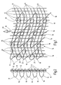
- das Gewebebild des erfindungsgemäßen Haftverschlußteils in Draufsicht;
- Fig.2
- eine Seitendarstellung auf das flächige Haftverschlußteil nach der Fig. 1.
This show in principle and not to scale representation of the
- Fig.1
- the fabric image of the adhesive closure part according to the invention in plan view;
- Fig.2
- a side view of the flat adhesive closure part according to FIG. 1.
Die Fig.1 zeigt ausschnittsweise eine Draufsicht auf das erfindungsgemäße flächenförmige Haftverschlußteil. Das dahingehende Haftverschlußteil läßt sich innerhalb der Bildebene sowohl in der einen wie auch in der anderen Bildrichtung beliebig verlängern und die geometrischen Abmessungen des Flächengebildes sind abhängig von den Vorgaben der Webeinrichtung, auf der das Haftverschlußteil gefertigt wird. Das Haftverschlußteil besteht aus Kettfäden 10 und Schußfäden 12, die in Queranordnung miteinander verwebt das Grundgewebe 14 für das Haftverschlußteil bilden. Des weiteren ist das Grundgewebe 14 mit Funktionsfäden 16 in der Art von Polfäden ausgebildet. Der jeweilige Funktionsfaden 16 bildet dann für das flächenförmige Haftverschlußteil die einzelnen Verschlußelemente 18 aus.1 shows a detail of a plan view of the inventive sheet-like adhesive closure part. The pertinent adhesive fastener part can be arbitrarily extended within the image plane both in the one and in the other image direction and the geometric dimensions of the sheet are dependent on the specifications of the weaving device on which the adhesive closure part is made. The fastener part consists of
Des weiteren ist in Blickrichtung auf die Fig.1 gesehen auf ihrer Oberseite mit einem Pfeil 20 die Produktionsrichtung für das Haftverschlußteil wiedergegeben. Bei der gezeigten Anordnung nach der Fig.1 sind die jeweiligen Schußfäden 12 in der Art einer Sinus- oder Kosinuswelle bogenförmig ausgebildet und an den Kreuzungsstellen zwischen Kettfäden 10 und Schußfäden 12 verlaufen die Kettfäden 10 parallel zur Produktionsrichtung 20 sowie parallel zueinander in geradliniger Anordnung. Bei nicht näher dargestellten Ausführungsformen des erfindungsgemäßen Haftverschlußteils wäre es darüber hinaus möglich, auch die Kettfäden 10 in der Art einer Sinus- oder Kosinuswelle bogenförmig zusätzlich oder alternativ derart auszubilden. Damit die Schußfäden 12 gemäß der Darstellung nach der Fig.1 einen bogenförmigen Verlauf erhalten, weist der hierfür vorgesehene Herstellwebstuhl (nicht dargestellt) einen entsprechend wellenförmig ausgebildeten Webblatteinsatz auf in der Art der benötigten Sinus- oder Kosinuswelle. Mithin läßt sich der erfindungsgemäße Haftverschluß mit hoher Produktionsgeschwindigkeit in großen Mengen zur Verfügung stellen und das sinusförmige oder kosinusförmige Webblatt (nicht dargestellt) greift quer zur Produktionsrichtung 20 zur Herstellung des bogenförmigen Schußfadenverlaufs dergestalt in das jeweilige Grundgewebe 14 ein.Furthermore, viewed in the direction of view of FIG. 1, the production direction for the adhesive closure part is reproduced on its upper side with an
Bei der Ausführungsform nach der Fig.1 sind aber nur die Schußfäden 12 bogenförmig im Grundgewebe 14 verlaufend angeordnet, wobei der jeweilige Schußfaden 12 in alternierender Reihenfolge einen Kettfaden 10 übergreift und den in Reihe unmittelbar nachfolgenden untergreift. Der jeweilige Funktionsfaden 16 verläuft zumindest teilweise zwischen zwei benachbarten Kettfäden 10 im Grundgewebe 14, wobei bei der in der Fig. 1 gezeigten Anordnung in der Reihe dabei jeder vierte Schußfaden 12 untergriffen und die anderen Schußfäden 12 übergriffen sind. An der Stelle des jeweiligen Untergriffs des Grundgewebes 14 bildet der Funktionsfaden 16 eine darüberliegende Schlaufe 22 aus, wobei nachfolgend unmittelbar eine weitere Schlaufe 24 ausgebildet ist, so daß eine Art V-Bindung verwirklicht ist. Es sind hier aber auch andere Bindungsarten denkbar, beispielsweise das Einbinden des Funktionsfadens 16 in W-förmiger Art od. dgl..In the embodiment of Figure 1 but only the
Die genannten Schlaufen 22,24 bilden die Verschlußelemente 18 und bleiben die Schlaufen 22,24, wie dargestellt, geschlossen, entsteht dergestalt eine Art Flausch-Haftverschlußteil, wobei haken- oder pilzartige Verschlußelemente in die dahingehenden Schlaufen 22,24 eingreifen können, um dergestalt einen lösbaren Haftverschluß zu erhalten. Es besteht aber auch die Möglichkeit, die Schlaufen 22,24 aufzuschneiden, so daß dergestalt dann ein Verschlußhaken entsteht, der mit korrespondierendem Vlies- oder Flauschmaterial eines anderen, nicht näher dargestellten Verschlußteils verhakbar ist. Sofern man den Trenn- oder Schneidvorgang thermisch durchführt, und insbesondere die freien Schlaufenenden dann noch weiter erhitzt, schrumpfen die Enden zusammen und bilden dabei pilzartige Verschlußköpfe aus, so daß die Verschlußhaken auch pilzförmig (nicht dargestellt) sein können. Auch ist es dergestalt möglich, kombinierte Verschlüsse, also solche mit haken- und schlaufenförmigen Elementen auf einem gemeinsamen Grundgewebe 14 zu erzeugen.The said
Wie insbesondere die Darstellung nach der Fig.2 zeigt, kann ein einzelner Schußfaden 12 auch aus einem Schußfadenpaar bestehen oder mehrfädig sein. Dies gilt auch für die Kettfäden 10, die gemäß der Querschnitts- oder Ansichtsdarstellung nach der Fig.2 in alternierende Reihenfolge jeweils ein Paar an Schußfäden 12 übergreifen, um nachfolgend einen Untergriff dieses Schußfadenpaares 12 vorzunehmen. Der jeweilige Funktions- oder Polfaden 16 übergreift dabei unter Auslassung jeweils eines Schußfadenpaares 12 die beiden darauffolgenden Schußfadenpaare 12 in der gezeigten Reihe.As shown in particular in the illustration according to FIG. 2, a
Wie sich des weiteren aus den beiden Abbildungen ergibt, untergreift die jeweils weitere Schlaufe 24 für einen Untergriff des Grundgewebes 14 einen Schußfaden 12, der in Blickrichtung auf die Fig. 1 gesehen um zwei Kettfäden 10 und zwei Schußfäden 12 seitlich versetzt von der Stelle angeordnet ist, wo die vorangehende Schlaufe 22 ihre Lage auf dem Grundgewebe 14 hat. Auf dem Grundgewebe 14 sind also die Schlaufen der ersten Art 22 und der weiteren Art 24 versetzt zueinander angeordnet, wobei die Schlaufen der ersten Art 22 im wesentlichen geschlossene O-förmige Schlaufen ausbilden und die Schlaufen der weiteren Art 24 sind V- oder U-förmig ausgebildet. Ein sog. Rapport für einen Funktionsfaden 16 wiederholt sich in Richtung der Schußfäden 12 nach fünf Kettfäden 10. Ferner können die Fadensysteme aus textilen Fasern bestehen, bevorzugt aber sind sie aus einem Kunststoffmaterial, insbesondere Nylon oder Polypropylen - Material gebildet. Ferner besteht auch die Möglichkeit, metallische Fadensysteme für den aufgezeigten erfindungsgemäßen Verschluß zumindest teilweise zu verwenden.As is further apparent from the two figures, engages the respective
Durch die wellenförmige Anordnung der Schußfäden 12 ist erreicht, daß beim Abschälen und mithin beim Lösen des Verschlusses über die korrespondierend versetzte Anordnung der Schlaufen 22,24 - auch als Hakenmaterial ausgebildet - in Abschälrichtung ein erhöhter Widerstand entgegensteht, was das Verschlußkraftverhalten begünstigt und somit hohe Haftsowie Schälfestigkeitswerte für den Verschluß ergibt.
In Abhängigkeit der Ausgestaltung des gewählten Verschlusses ist es darüber hinaus möglich, die Haftwerte für den Verschluß weitestgehend konstant einzustellen, so daß immer mit ein und derselben Lösekraft der Haftverschluß gelöst werden kann.Due to the undulating arrangement of the
Depending on the configuration of the selected closure, it is also possible to set the adhesive values for the closure largely constant, so that always with one and the same release force of the adhesive closure can be solved.
Claims (10)
- Two-dimensional adhesive closure part for an adhesive closure, whereby disconnectable closure elements (18) corresponding with each other can be engaged, with a base weave (14) made from weave threads (10) and weft threads (12) and with at least one function thread (16), the same partially engaging the base weave (14) and forming the closure elements (18), characterised in that either the weft threads (12) and/or the weave threads (10) extend along the level of the base weave (14) in a wave- or arc-shaped way, and in that the relevant part of the arc or the wave is formed in the way of a sinus or cosinus wave.
- Adhesive closure part according to Claim 1, characterised in that only the weft threads (12) extend in a wave- or arc-shaped way within the base weave (14), and in that the relevant weft thread (12) straddles a weave thread (10) in alternating sequence and underlies the immediately adjacent one in the same row.
- Adhesive closure part according to Claim 1 or 2, characterised in that the relevant function thread (16) extends at least in part between two adjacent weave threads (10) in the base weave (14), and in that every fourth weft thread (12) is underlayed and the other weft threads (12) are straddled.
- Adhesive closure part according to Claim 3, characterised in that the function thread (16) forms an overlaying loop (22) instead of underlaying the base weave (14), and in that a further loop (24) is formed immediately following the same.
- Adhesive closure part according to Claim 4, characterised in that each further loop (24) underlays a weft thread (12) for underlaying the base weave (14), the same being offset from the point where the previous loop (22) lies on the base wave (14) in a sideways direction by two weave threads (10) and two weft threads (12).
- Adhesive closure part according to Claim 5, characterised in that the rapport for a function thread (16) is repeated in the direction of the weft threads (12) after five weave threads (10).
- Adhesive closure part according to one of the Claims 1 to 6, characterised in that the relevant function thread (16) is cut open at the point where the same forms a loop (22, 24) and thus results in a closure hook, or in that the cut ends of the closure elements (18) form mushroom-shaped closure heads following an application of thermal energy - assuming that the function thread (16) consists of a plastic material.
- Adhesive closure part according to Claim 7, characterised in that the loops of the first type (22) and the further type (24) are arranged offset from each other on the base weave (14), and in that the loops of the first type (22) are substantially formed as closed circular loops, and the loops of the further type (24) are V- or U-shaped.
- Adhesive closure part according to one of the Claims 1 to 8, characterised in that a weft thread (12) or a weave thread (10 or a function thread (16) consists of a thread system with several threads.
- Adhesive closure part according to one of the Claims 1 to 9, characterised in that the weft threads (12), the weave threads (10) and the function threads (16) consist of a nylon or polypropylene material.
Applications Claiming Priority (3)
| Application Number | Priority Date | Filing Date | Title |
|---|---|---|---|
| DE10240986 | 2002-09-05 | ||
| DE10240986A DE10240986B3 (en) | 2002-09-05 | 2002-09-05 | Flat adhesive closure part comprises detachable closure elements, a backing fabric made from warp thread and weft thread, and a functional thread partially interacting with the backing fabric |
| PCT/EP2003/007372 WO2004021823A1 (en) | 2002-09-05 | 2003-07-09 | Planar adhesive closure piece |
Publications (2)
| Publication Number | Publication Date |
|---|---|
| EP1534096A1 EP1534096A1 (en) | 2005-06-01 |
| EP1534096B1 true EP1534096B1 (en) | 2007-06-27 |
Family
ID=30128855
Family Applications (1)
| Application Number | Title | Priority Date | Filing Date |
|---|---|---|---|
| EP03793616A Expired - Lifetime EP1534096B1 (en) | 2002-09-05 | 2003-07-09 | Planar adhesive closure piece |
Country Status (7)
| Country | Link |
|---|---|
| US (1) | US7351464B2 (en) |
| EP (1) | EP1534096B1 (en) |
| JP (1) | JP4542428B2 (en) |
| AT (1) | ATE365477T1 (en) |
| DE (2) | DE10240986B3 (en) |
| ES (1) | ES2287560T3 (en) |
| WO (1) | WO2004021823A1 (en) |
Cited By (1)
| Publication number | Priority date | Publication date | Assignee | Title |
|---|---|---|---|---|
| DE102008048205A1 (en) | 2008-09-20 | 2010-04-01 | Gottlieb Binder Gmbh & Co. Kg | Process for the surface functionalization of an adhesive closure part and adhesive closure part produced by the process |
Families Citing this family (14)
| Publication number | Priority date | Publication date | Assignee | Title |
|---|---|---|---|---|
| DE102006002339A1 (en) * | 2006-01-18 | 2007-07-19 | Gottlieb Binder Gmbh & Co. Kg | Flame retardant fastener for e.g. fastening wall panel to support structure, has fastener part with base fabric including carrier layer partially on rear side, where layer is formed with flame resistant medium or active extinguishing medium |
| DE202006002409U1 (en) | 2006-01-18 | 2006-04-20 | Gottlieb Binder Gmbh & Co. Kg | Flame retardant closure |
| DE102009021094A1 (en) | 2009-05-13 | 2010-11-18 | Gottlieb Binder Gmbh & Co. Kg | Mechanical adhesive closure part |
| DE102009032301A1 (en) | 2009-07-09 | 2011-01-13 | Gottlieb Binder Gmbh & Co. Kg | Fastener part |
| DE102013010085A1 (en) | 2013-06-10 | 2014-12-11 | Gottlieb Binder Gmbh & Co. Kg | Flat adhesive closure part and cleaning system with such a sheet-like adhesive closure part |
| DE102013022112A1 (en) | 2013-12-27 | 2015-07-02 | Gottlieb Binder Gmbh & Co. Kg | Flame retardant closure and flame-retardant finish or coating |
| DE102014003211A1 (en) | 2014-03-07 | 2015-09-10 | Gottlieb Binder Gmbh & Co. Kg | Joining method together with functional part usable therefor and flame retardant overall system produced thereafter |
| DE102017011244A1 (en) | 2017-12-06 | 2019-06-06 | Gottlieb Binder Gmbh & Co. Kg | Fastener system |
| FR3116419A1 (en) | 2020-11-23 | 2022-05-27 | Aplix | Improved retainer for protecting retainers |
| DE102021000393A1 (en) | 2021-01-27 | 2022-07-28 | Gottlieb Binder Gmbh & Co. Kg | Fastening device together with a method for producing such a fastening device and a fastening system manufactured with such a fastening device |
| DE102021003311A1 (en) | 2021-06-26 | 2022-12-29 | Gottlieb Binder Gmbh & Co. Kg | Process for manufacturing a touch-and-close fastener part |
| DE102021005460A1 (en) | 2021-11-04 | 2023-05-04 | Gottlieb Binder Gmbh & Co. Kg | connection system |
| DE102021006483A1 (en) | 2021-12-30 | 2023-07-06 | Gottlieb Binder Gmbh & Co. Kg | locking system |
| DE102022127854A1 (en) | 2022-10-24 | 2024-04-25 | Gottlieb Binder Gmbh & Co. Kg | Closure part |
Family Cites Families (6)
| Publication number | Priority date | Publication date | Assignee | Title |
|---|---|---|---|---|
| US5040275A (en) * | 1990-06-01 | 1991-08-20 | Minnesota Mining And Manufacturing Company | Strip material used for forming fasteners |
| JPH0652521U (en) * | 1992-12-28 | 1994-07-19 | 吉田工業株式会社 | Male fastening material for hook-and-loop fasteners with high-density hook pieces |
| JP2828593B2 (en) | 1994-04-22 | 1998-11-25 | ワイケイケイ株式会社 | A hook-and-loop fastener having a thick base cloth |
| US6076238A (en) * | 1999-04-13 | 2000-06-20 | 3M Innovative Properties Company | Mechanical fastener |
| JP3626389B2 (en) | 2000-02-29 | 2005-03-09 | Ykk株式会社 | Hook-and-loop fastener |
| JP3647357B2 (en) * | 2000-04-28 | 2005-05-11 | Ykk株式会社 | Hook-and-loop fastener |
-
2002
- 2002-09-05 DE DE10240986A patent/DE10240986B3/en not_active Withdrawn - After Issue
-
2003
- 2003-07-09 EP EP03793616A patent/EP1534096B1/en not_active Expired - Lifetime
- 2003-07-09 ES ES03793616T patent/ES2287560T3/en not_active Expired - Lifetime
- 2003-07-09 AT AT03793616T patent/ATE365477T1/en active
- 2003-07-09 US US10/526,463 patent/US7351464B2/en not_active Expired - Lifetime
- 2003-07-09 DE DE50307576T patent/DE50307576D1/en not_active Expired - Lifetime
- 2003-07-09 JP JP2004533248A patent/JP4542428B2/en not_active Expired - Lifetime
- 2003-07-09 WO PCT/EP2003/007372 patent/WO2004021823A1/en active IP Right Grant
Non-Patent Citations (1)
| Title |
|---|
| None * |
Cited By (1)
| Publication number | Priority date | Publication date | Assignee | Title |
|---|---|---|---|---|
| DE102008048205A1 (en) | 2008-09-20 | 2010-04-01 | Gottlieb Binder Gmbh & Co. Kg | Process for the surface functionalization of an adhesive closure part and adhesive closure part produced by the process |
Also Published As
| Publication number | Publication date |
|---|---|
| JP4542428B2 (en) | 2010-09-15 |
| ATE365477T1 (en) | 2007-07-15 |
| WO2004021823A1 (en) | 2004-03-18 |
| US7351464B2 (en) | 2008-04-01 |
| ES2287560T3 (en) | 2007-12-16 |
| DE50307576D1 (en) | 2007-08-09 |
| EP1534096A1 (en) | 2005-06-01 |
| JP2005537833A (en) | 2005-12-15 |
| DE10240986B3 (en) | 2004-02-12 |
| US20050268439A1 (en) | 2005-12-08 |
Similar Documents
| Publication | Publication Date | Title |
|---|---|---|
| EP1534096B1 (en) | Planar adhesive closure piece | |
| DE69104417T2 (en) | Velcro-like element for a one-piece cast surface fastener. | |
| DE19801278C2 (en) | Cast engagement part for a surface fastener | |
| DE2112238A1 (en) | Surface fastener | |
| DE2120200A1 (en) | Closing part of a surface zipper | |
| DE19908874B4 (en) | Surface fastener made of fibers and process for its manufacture | |
| DE3012432C2 (en) | Velvet-like tape for a surface zipper | |
| DE3012431C2 (en) | Surface zipper | |
| DE69909984T2 (en) | Surface fastener BAND | |
| DE69621524T2 (en) | Fastening device for sheet-like object | |
| DE2950808C2 (en) | Zipper tape | |
| EP0806158B1 (en) | Fastening device comprising a net and a touch fastener | |
| EP0389831B1 (en) | Device for binding elongated objects | |
| EP1949810B1 (en) | Hook and loop fastener part made from threads as finished flat good | |
| EP3694368B1 (en) | Adhesive closure system | |
| DE69608977T2 (en) | Hook for a cast surface fastener | |
| EP1030569A1 (en) | Fastener for elastic materials | |
| CH649453A5 (en) | ZIPPER STRIPS WITH VENTILATION OPENINGS. | |
| EP2451305B1 (en) | Adhesive fastening part | |
| DE2929329A1 (en) | Surface fastener having inclined spines with downturned tips - to increase hold retention with varying tensional load | |
| DE2906655C2 (en) | Textile adhesive fastener half | |
| DE3011277C2 (en) | Zipper tape | |
| DE2841630C2 (en) | Zipper tape | |
| DE10003658B4 (en) | Device for depositing a group of threads | |
| DE2805954C2 (en) |
Legal Events
| Date | Code | Title | Description |
|---|---|---|---|
| PUAI | Public reference made under article 153(3) epc to a published international application that has entered the european phase |
Free format text: ORIGINAL CODE: 0009012 |
|
| 17P | Request for examination filed |
Effective date: 20050128 |
|
| AK | Designated contracting states |
Kind code of ref document: A1 Designated state(s): AT BE BG CH CY CZ DE DK EE ES FI FR GB GR HU IE IT LI LU MC NL PT RO SE SI SK TR |
|
| GRAP | Despatch of communication of intention to grant a patent |
Free format text: ORIGINAL CODE: EPIDOSNIGR1 |
|
| GRAS | Grant fee paid |
Free format text: ORIGINAL CODE: EPIDOSNIGR3 |
|
| GRAA | (expected) grant |
Free format text: ORIGINAL CODE: 0009210 |
|
| AK | Designated contracting states |
Kind code of ref document: B1 Designated state(s): AT BE BG CH CY CZ DE DK EE ES FI FR GB GR HU IE IT LI LU MC NL PT RO SE SI SK TR |
|
| REG | Reference to a national code |
Ref country code: GB Ref legal event code: FG4D Free format text: NOT ENGLISH |
|
| GBT | Gb: translation of ep patent filed (gb section 77(6)(a)/1977) |
Effective date: 20070627 |
|
| REG | Reference to a national code |
Ref country code: CH Ref legal event code: NV Representative=s name: ISLER & PEDRAZZINI AG Ref country code: CH Ref legal event code: EP |
|
| REG | Reference to a national code |
Ref country code: IE Ref legal event code: FG4D Free format text: LANGUAGE OF EP DOCUMENT: GERMAN |
|
| REF | Corresponds to: |
Ref document number: 50307576 Country of ref document: DE Date of ref document: 20070809 Kind code of ref document: P |
|
| REG | Reference to a national code |
Ref country code: CH Ref legal event code: PCAR Free format text: ISLER & PEDRAZZINI AG;POSTFACH 1772;8027 ZUERICH (CH) |
|
| REG | Reference to a national code |
Ref country code: SE Ref legal event code: TRGR |
|
| ET | Fr: translation filed | ||
| REG | Reference to a national code |
Ref country code: ES Ref legal event code: FG2A Ref document number: 2287560 Country of ref document: ES Kind code of ref document: T3 |
|
| REG | Reference to a national code |
Ref country code: IE Ref legal event code: FD4D |
|
| PG25 | Lapsed in a contracting state [announced via postgrant information from national office to epo] |
Ref country code: PT Free format text: LAPSE BECAUSE OF FAILURE TO SUBMIT A TRANSLATION OF THE DESCRIPTION OR TO PAY THE FEE WITHIN THE PRESCRIBED TIME-LIMIT Effective date: 20071127 Ref country code: IE Free format text: LAPSE BECAUSE OF FAILURE TO SUBMIT A TRANSLATION OF THE DESCRIPTION OR TO PAY THE FEE WITHIN THE PRESCRIBED TIME-LIMIT Effective date: 20070627 Ref country code: BG Free format text: LAPSE BECAUSE OF FAILURE TO SUBMIT A TRANSLATION OF THE DESCRIPTION OR TO PAY THE FEE WITHIN THE PRESCRIBED TIME-LIMIT Effective date: 20070927 Ref country code: SI Free format text: LAPSE BECAUSE OF FAILURE TO SUBMIT A TRANSLATION OF THE DESCRIPTION OR TO PAY THE FEE WITHIN THE PRESCRIBED TIME-LIMIT Effective date: 20070627 |
|
| PG25 | Lapsed in a contracting state [announced via postgrant information from national office to epo] |
Ref country code: MC Free format text: LAPSE BECAUSE OF NON-PAYMENT OF DUE FEES Effective date: 20070731 Ref country code: GR Free format text: LAPSE BECAUSE OF FAILURE TO SUBMIT A TRANSLATION OF THE DESCRIPTION OR TO PAY THE FEE WITHIN THE PRESCRIBED TIME-LIMIT Effective date: 20070928 Ref country code: DK Free format text: LAPSE BECAUSE OF FAILURE TO SUBMIT A TRANSLATION OF THE DESCRIPTION OR TO PAY THE FEE WITHIN THE PRESCRIBED TIME-LIMIT Effective date: 20070627 |
|
| PLBE | No opposition filed within time limit |
Free format text: ORIGINAL CODE: 0009261 |
|
| STAA | Information on the status of an ep patent application or granted ep patent |
Free format text: STATUS: NO OPPOSITION FILED WITHIN TIME LIMIT |
|
| PG25 | Lapsed in a contracting state [announced via postgrant information from national office to epo] |
Ref country code: RO Free format text: LAPSE BECAUSE OF FAILURE TO SUBMIT A TRANSLATION OF THE DESCRIPTION OR TO PAY THE FEE WITHIN THE PRESCRIBED TIME-LIMIT Effective date: 20070627 |
|
| 26N | No opposition filed |
Effective date: 20080328 |
|
| PG25 | Lapsed in a contracting state [announced via postgrant information from national office to epo] |
Ref country code: EE Free format text: LAPSE BECAUSE OF FAILURE TO SUBMIT A TRANSLATION OF THE DESCRIPTION OR TO PAY THE FEE WITHIN THE PRESCRIBED TIME-LIMIT Effective date: 20070627 |
|
| PG25 | Lapsed in a contracting state [announced via postgrant information from national office to epo] |
Ref country code: FI Free format text: LAPSE BECAUSE OF FAILURE TO SUBMIT A TRANSLATION OF THE DESCRIPTION OR TO PAY THE FEE WITHIN THE PRESCRIBED TIME-LIMIT Effective date: 20070627 |
|
| PG25 | Lapsed in a contracting state [announced via postgrant information from national office to epo] |
Ref country code: CY Free format text: LAPSE BECAUSE OF FAILURE TO SUBMIT A TRANSLATION OF THE DESCRIPTION OR TO PAY THE FEE WITHIN THE PRESCRIBED TIME-LIMIT Effective date: 20070627 |
|
| PG25 | Lapsed in a contracting state [announced via postgrant information from national office to epo] |
Ref country code: LU Free format text: LAPSE BECAUSE OF NON-PAYMENT OF DUE FEES Effective date: 20070709 |
|
| PG25 | Lapsed in a contracting state [announced via postgrant information from national office to epo] |
Ref country code: HU Free format text: LAPSE BECAUSE OF FAILURE TO SUBMIT A TRANSLATION OF THE DESCRIPTION OR TO PAY THE FEE WITHIN THE PRESCRIBED TIME-LIMIT Effective date: 20071228 |
|
| REG | Reference to a national code |
Ref country code: FR Ref legal event code: PLFP Year of fee payment: 14 |
|
| REG | Reference to a national code |
Ref country code: FR Ref legal event code: PLFP Year of fee payment: 15 |
|
| REG | Reference to a national code |
Ref country code: FR Ref legal event code: PLFP Year of fee payment: 16 |
|
| PGFP | Annual fee paid to national office [announced via postgrant information from national office to epo] |
Ref country code: SK Payment date: 20220517 Year of fee payment: 20 Ref country code: IT Payment date: 20220616 Year of fee payment: 20 Ref country code: GB Payment date: 20220519 Year of fee payment: 20 Ref country code: FR Payment date: 20220524 Year of fee payment: 20 Ref country code: CZ Payment date: 20220517 Year of fee payment: 20 |
|
| PGFP | Annual fee paid to national office [announced via postgrant information from national office to epo] |
Ref country code: TR Payment date: 20220525 Year of fee payment: 20 Ref country code: BE Payment date: 20220615 Year of fee payment: 20 |
|
| PGFP | Annual fee paid to national office [announced via postgrant information from national office to epo] |
Ref country code: NL Payment date: 20220725 Year of fee payment: 20 |
|
| PGFP | Annual fee paid to national office [announced via postgrant information from national office to epo] |
Ref country code: SE Payment date: 20220715 Year of fee payment: 20 Ref country code: ES Payment date: 20220801 Year of fee payment: 20 Ref country code: DE Payment date: 20220731 Year of fee payment: 20 Ref country code: AT Payment date: 20220714 Year of fee payment: 20 |
|
| PGFP | Annual fee paid to national office [announced via postgrant information from national office to epo] |
Ref country code: CH Payment date: 20220713 Year of fee payment: 20 |
|
| REG | Reference to a national code |
Ref country code: DE Ref legal event code: R082 Ref document number: 50307576 Country of ref document: DE Representative=s name: KOHLER SCHMID MOEBUS PATENTANWAELTE PARTNERSCH, DE Ref country code: DE Ref legal event code: R082 Ref document number: 50307576 Country of ref document: DE |
|
| REG | Reference to a national code |
Ref country code: DE Ref legal event code: R082 Ref document number: 50307576 Country of ref document: DE Representative=s name: KOHLER SCHMID MOEBUS PATENTANWAELTE PARTNERSCH, DE |
|
| REG | Reference to a national code |
Ref country code: DE Ref legal event code: R071 Ref document number: 50307576 Country of ref document: DE |
|
| REG | Reference to a national code |
Ref country code: NL Ref legal event code: MK Effective date: 20230708 |
|
| REG | Reference to a national code |
Ref country code: CH Ref legal event code: PL |
|
| REG | Reference to a national code |
Ref country code: SK Ref legal event code: MK4A Ref document number: E 2323 Country of ref document: SK Expiry date: 20230709 Ref country code: ES Ref legal event code: FD2A Effective date: 20230726 |
|
| REG | Reference to a national code |
Ref country code: BE Ref legal event code: MK Effective date: 20230709 |
|
| PG25 | Lapsed in a contracting state [announced via postgrant information from national office to epo] |
Ref country code: CZ Free format text: LAPSE BECAUSE OF EXPIRATION OF PROTECTION Effective date: 20230709 |
|
| REG | Reference to a national code |
Ref country code: GB Ref legal event code: PE20 Expiry date: 20230708 |
|
| REG | Reference to a national code |
Ref country code: AT Ref legal event code: MK07 Ref document number: 365477 Country of ref document: AT Kind code of ref document: T Effective date: 20230709 |
|
| REG | Reference to a national code |
Ref country code: SE Ref legal event code: EUG |
|
| PG25 | Lapsed in a contracting state [announced via postgrant information from national office to epo] |
Ref country code: GB Free format text: LAPSE BECAUSE OF EXPIRATION OF PROTECTION Effective date: 20230708 Ref country code: ES Free format text: LAPSE BECAUSE OF EXPIRATION OF PROTECTION Effective date: 20230710 |
|
| PG25 | Lapsed in a contracting state [announced via postgrant information from national office to epo] |
Ref country code: SK Free format text: LAPSE BECAUSE OF EXPIRATION OF PROTECTION Effective date: 20230709 |