JP4542428B2 - Face adhesive closure piece - Google Patents
Face adhesive closure piece Download PDFInfo
- Publication number
- JP4542428B2 JP4542428B2 JP2004533248A JP2004533248A JP4542428B2 JP 4542428 B2 JP4542428 B2 JP 4542428B2 JP 2004533248 A JP2004533248 A JP 2004533248A JP 2004533248 A JP2004533248 A JP 2004533248A JP 4542428 B2 JP4542428 B2 JP 4542428B2
- Authority
- JP
- Japan
- Prior art keywords
- filament
- weft
- loop
- filaments
- adhesive fastener
- Prior art date
- Legal status (The legal status is an assumption and is not a legal conclusion. Google has not performed a legal analysis and makes no representation as to the accuracy of the status listed.)
- Expired - Lifetime
Links
Images

Classifications
-
- A—HUMAN NECESSITIES
- A44—HABERDASHERY; JEWELLERY
- A44B—BUTTONS, PINS, BUCKLES, SLIDE FASTENERS, OR THE LIKE
- A44B18/00—Fasteners of the touch-and-close type; Making such fasteners
- A44B18/0069—Details
- A44B18/0092—Details flame retardant
-
- A—HUMAN NECESSITIES
- A44—HABERDASHERY; JEWELLERY
- A44B—BUTTONS, PINS, BUCKLES, SLIDE FASTENERS, OR THE LIKE
- A44B18/00—Fasteners of the touch-and-close type; Making such fasteners
- A44B18/0023—Woven or knitted fasteners
-
- A—HUMAN NECESSITIES
- A44—HABERDASHERY; JEWELLERY
- A44B—BUTTONS, PINS, BUCKLES, SLIDE FASTENERS, OR THE LIKE
- A44B18/00—Fasteners of the touch-and-close type; Making such fasteners
- A44B18/0023—Woven or knitted fasteners
- A44B18/0038—Male or hook elements
- A44B18/0042—Male or hook elements of a mushroom type
-
- Y—GENERAL TAGGING OF NEW TECHNOLOGICAL DEVELOPMENTS; GENERAL TAGGING OF CROSS-SECTIONAL TECHNOLOGIES SPANNING OVER SEVERAL SECTIONS OF THE IPC; TECHNICAL SUBJECTS COVERED BY FORMER USPC CROSS-REFERENCE ART COLLECTIONS [XRACs] AND DIGESTS
- Y10—TECHNICAL SUBJECTS COVERED BY FORMER USPC
- Y10T—TECHNICAL SUBJECTS COVERED BY FORMER US CLASSIFICATION
- Y10T24/00—Buckles, buttons, clasps, etc.
- Y10T24/27—Buckles, buttons, clasps, etc. including readily dissociable fastener having numerous, protruding, unitary filaments randomly interlocking with, and simultaneously moving towards, mating structure [e.g., hook-loop type fastener]
- Y10T24/2733—Buckles, buttons, clasps, etc. including readily dissociable fastener having numerous, protruding, unitary filaments randomly interlocking with, and simultaneously moving towards, mating structure [e.g., hook-loop type fastener] having filaments formed from continuous element interwoven or knitted into distinct, mounting surface fabric
-
- Y—GENERAL TAGGING OF NEW TECHNOLOGICAL DEVELOPMENTS; GENERAL TAGGING OF CROSS-SECTIONAL TECHNOLOGIES SPANNING OVER SEVERAL SECTIONS OF THE IPC; TECHNICAL SUBJECTS COVERED BY FORMER USPC CROSS-REFERENCE ART COLLECTIONS [XRACs] AND DIGESTS
- Y10—TECHNICAL SUBJECTS COVERED BY FORMER USPC
- Y10T—TECHNICAL SUBJECTS COVERED BY FORMER US CLASSIFICATION
- Y10T428/00—Stock material or miscellaneous articles
- Y10T428/23907—Pile or nap type surface or component
- Y10T428/23957—Particular shape or structure of pile
- Y10T428/23964—U-, V-, or W-shaped or continuous strand, filamentary material
-
- Y—GENERAL TAGGING OF NEW TECHNOLOGICAL DEVELOPMENTS; GENERAL TAGGING OF CROSS-SECTIONAL TECHNOLOGIES SPANNING OVER SEVERAL SECTIONS OF THE IPC; TECHNICAL SUBJECTS COVERED BY FORMER USPC CROSS-REFERENCE ART COLLECTIONS [XRACs] AND DIGESTS
- Y10—TECHNICAL SUBJECTS COVERED BY FORMER USPC
- Y10T—TECHNICAL SUBJECTS COVERED BY FORMER US CLASSIFICATION
- Y10T428/00—Stock material or miscellaneous articles
- Y10T428/24—Structurally defined web or sheet [e.g., overall dimension, etc.]
- Y10T428/24008—Structurally defined web or sheet [e.g., overall dimension, etc.] including fastener for attaching to external surface
- Y10T428/24017—Hook or barb
Abstract
Description
本願発明は、互いに対応する固定エレメントが分離可能に係合する接着ファスナーに関し、ねじれフィラメントと横糸フィラメントから構成されるベースファブリックと少なくとも部分的にベースファブリックへ伸びて固定エレメントを形成する少なくとも1つの機能フィラメントから構成される面接着クロージャー片に関するものである。 The present invention relates to an adhesive fastener in which fixing elements corresponding to each other are separably engaged, and at least one function of forming a fixing element by extending to the base fabric at least partially to a base fabric composed of twisted filaments and weft filaments The present invention relates to a surface-bonded closure piece composed of a filament.
すでに実用化された、ゆがみフィラメント、横糸フィラメント及び機能フィラメント(これらは織物繊維のみならず、プラスチックや金属繊維で構成される場合もある。)によって織られる接着ファスナー部分は市場で入手することができる。機能フィラメントがマルチフィラメント糸により作られる場合は、ベースファブリック(ゆがみフィラメント及び横糸フィラメントから作られる)上にループ状のホックエレメントを形成する。一方、機能フィラメントがモノフィラメントから作られ、熱的方法によりそれぞれのループが切り開かれ又は分離されることにより、対応するフリースループ材と係合する固定ホックを得ることができる。フリーループ端の分離過程が、例えば溶けてオープンになるような熱処理を経れば、プラスチック固有の現象の結果として固定エレメントとなるマッシュルーム形状の固定ヘッドを作ることができる。 Adhesive fastener parts woven with warped filaments, weft filaments and functional filaments already in practical use (these may be made of plastic or metal fibers as well as textile fibers) are commercially available . When the functional filament is made of multifilament yarn, a loop-like hook element is formed on the base fabric (made of warp filament and weft filament). On the other hand, the functional filaments are made from monofilaments, and the respective loops are cut or separated by a thermal method to obtain a fixed hook that engages the corresponding fleece loop material. If the separation process of the free loop end undergoes a heat treatment that melts and opens, for example, a mushroom-shaped fixed head that becomes a fixed element as a result of a phenomenon unique to plastic can be made.
接着ファスナー部分を開いてみることで剥離抵抗がわかるが、接着ファスナーを形成している一対の面ファスナーを引き離すためには、比較的強い力が必要とされなければならない。ところが、固定部分に相当する固定エレメントは相手側との関係において特定の方向性(統計学見地による規則的な方向性)を帯びてしまう。その方向においては、互いに接着していた固定エレメントが簡単に滑り離れて、外れてしまうことがある。この点については、実際の使用によって、接着し始めるとすぐにファスナーが外れることから明らかになった。 Although peeling resistance can be understood by opening the adhesive fastener portion, a relatively strong force must be required to separate the pair of surface fasteners forming the adhesive fastener. However, the fixed element corresponding to the fixed portion has a specific direction (regular direction from a statistical viewpoint) in relation to the other side. In that direction, the fixing elements that are bonded together can easily slip away and come off. In this regard, it became clear from actual use that the fasteners were removed as soon as they started to bond.
この問題を解決するために、合衆国特許5040275は、固定エレメントがサインカーブの通路に沿って配置され、マッシュルームヘッドの自由端とU型のホックから構成されるキャスト接着ファスナー部分が開示されている。これに加え、接着ファスナー(例えばマッシュルームホック)の形成において、ファスナーヘッドが各クリアスペースに入り込み、固定エレメントが適切に受け入れられて可能な限り抵抗なく係合できるように、U型固定エレメント間のサイン通路の横方向にスペースが確保されている。キャストファスナー(U型ホックエレメントは、ベースマトリクス材のキャストである。)の配置をサインカーブ通路とした結果、それぞれのサインカーブが相互に引き合わされてファスナーホックが力(障害及びそれに応じて剥離抵抗の増加という結果になるもの)を発生させるので、ファスナーを開ける際のはがし方向に生じる急速な滑りを防止できる。さらに、上記発明を改良したものとして、合衆国特許6076238では、固定エレメントを備えるホッキングパターンを前もって定めた無秩序なパターンとするものが開示されている。すなわち、サインカーブ形状よりも効果を大きくするために、固定エレメントはベースファブリックに可能な限り無造作に並べられる。しかしながら、これらのキャストプラスチックファスナーは、ひずみ/横糸フィラメントをそなえる織物として作ることができない。さらに、このファスナーの生産は、複雑でコストがかかってしまう。 In order to solve this problem, US Pat. No. 5,040,275 discloses a cast adhesive fastener portion in which a fixing element is disposed along a path of a sine curve and is composed of a free end of a mushroom head and a U-shaped hook. In addition, in the formation of adhesive fasteners (eg, mushroom hooks), the sign between the U-shaped fastening elements so that the fastener heads can enter each clear space and the fastening elements are properly received and engage with as little resistance as possible. Space is secured in the lateral direction of the passage. As a result of the arrangement of cast fasteners (U-shaped hook element is cast of base matrix material) as a sine curve path, each sine curve is attracted to each other, and the fastener hook is force (failure and corresponding peeling resistance) (Which results in an increase in the number of times) is generated, and rapid slipping in the peeling direction when the fastener is opened can be prevented. Further, as an improvement on the above invention, US Pat. No. 6,076,238 discloses a predetermined disordered pattern for a hooking pattern with a fixed element. That is, the fixing elements are arranged as randomly as possible on the base fabric in order to increase the effect over the sine curve shape. However, these cast plastic fasteners cannot be made as fabrics with strain / weft filaments. Furthermore, the production of this fastener is complicated and expensive.
この従来技術を踏まえて、本願発明は費用価値の高い方法で、織物技術により従来のファスナーよりも高い接着力を有するウエーブファスナーとしての面ファスナー部分を提供することを目的とする。この課題は、請求項1の全体により特定される特徴を有する面接着ファスナー部分により達成される。 In light of this prior art, the present invention aims to provide a hook-and-loop fastener portion as a wave fastener having a higher adhesive force than conventional fasteners by a textile technique in a cost-effective manner. This object is achieved by a surface-bonded fastener part having the characteristics specified in the entirety of claim 1.
接着ファスナーにおいて、ねじれフィラメントおよび/または横糸フィラメントをウエーブ形状又はカーブに形成する(請求項1)。これにより、接着ファスナーの固定エレメントにおける1方向に伸ばされた直線方向性は回避され、形状が曲げられることにより、明らかに固定エレメントの解放の抵抗が大きくなる(保持力が本質的に一定なので、計算できるはずである。)。従来技術と比べると剥離抵抗値ははっきりと増加する。これは、面接着ファスナー片はねじり及び横糸フィラメントによる織物により作られるからである。カーブまたはウエーブは、サインカーブまたはコサインカーブとしてもよい。 In the adhesive fastener, the twisted filament and / or the weft filament are formed into a wave shape or a curve (claim 1). As a result, the linear directionality extended in one direction in the fixing element of the adhesive fastener is avoided, and the bending of the shape obviously increases the resistance of releasing the fixing element (since the holding force is essentially constant, It should be possible to calculate.) Compared with the prior art, the peel resistance value is clearly increased. This is because the face-bonded fastener piece is made of a fabric made of twisted and weft filaments. The curve or wave may be a sine curve or a cosine curve.
本願発明に係る接着ファスナー部分の具体化において、横糸フィラメントは屈曲形状に伸びてベースファブリックを形成する。そして横糸フィラメントはねじれフィラメントの上へ、そしてすぐ後のねじれフィラメントの下へと交互に続いていく。これによって、ベースファブリック構造において、横糸フィラメントは強く固定される。一方でベースファブリック構造において、直線的に伸びるねじりフィラメントは、適切に横糸フィラメントを支える。 In the embodiment of the adhesive fastener portion according to the present invention, the weft filaments extend in a bent shape to form a base fabric. The weft filament then continues alternately on top of the twisted filament and then immediately below the twisted filament. Thereby, the weft filament is firmly fixed in the base fabric structure. On the other hand, in the base fabric structure, the linearly extending torsional filament properly supports the weft filament.
他のクレームにかかる接着ファスナー部分の具体化においては、機能フィラメントが少なくともベースファブリック内の隣接している2つのねじれフィラメントの間に部分的に伸び、機能フィラメントが4つ毎の横糸フィラメントの下へ伸び、そして他の横糸フィラメントの上に伸びる。機能フィラメントがベースファブリックの下に広がる前に、ループをベースファブリックの上に形成し、他のループがすぐにその後形成されるようにしてもよい。 In an embodiment of an adhesive fastener portion according to another claim, the functional filament extends at least partially between two adjacent twisted filaments in the base fabric, with the functional filament below every fourth weft filament. Elongate and stretch over other weft filaments. Before the functional filaments spread under the base fabric, a loop may be formed on the base fabric and other loops may be formed immediately thereafter.
ループはホックエレメントを係合するためのフリース材とされる。しかし、ループは後で切り開かれ、熱的に離されることによりファスナーホックを形成することができる。機能フィラメントはモノフィラメントにより形成されてもよい。接着分離ファスナーにおいてモノフィラメントは引き離す力の抵抗が適切であり、係合と解放の力を供給するものであって、製造が期待されている。その他の有効な具体化については、従属クレームに指定されている。 The loop is a fleece material for engaging the hook element. However, the loop can later be cut open and thermally released to form a fastener hook. The functional filament may be formed of a monofilament. In the adhesive separation fastener, the monofilament has an appropriate resistance to the pulling force and supplies the engaging and releasing force, and is expected to be manufactured. Other valid embodiments are specified in the dependent claims.
以下に本願発明の接着ファスナー部分について、図を参照しつつ、詳細に説明する。 Hereinafter, the adhesive fastener portion of the present invention will be described in detail with reference to the drawings.
図1は、本願発明に係るファスナー構造の上面図を表す。問題の接着ファスナー部分は、イラストの1方向または他の方向において任意の図の平面に伸ばされる。一方、平面に形成された幾何学的な大きさは、接着ファスナー部分が作り出されるウェービング機構に帰する値による。接着ファスナーはゆがみフィラメント10、横糸フィラメント12から成る。横糸フィラメント12はベースファブリック14を形成するために横に編まれていく。また、ベースファブリック14は毛糸としての機能フィラメント16より形成される。機能フィラメント16は個々の固定エレメント18を形成する。
FIG. 1 shows a top view of a fastener structure according to the present invention. The adhesive fastener part in question is stretched in the plane of any figure in one direction or the other in the illustration. On the other hand, the geometric size formed in the plane depends on the value attributed to the waving mechanism in which the adhesive fastener portion is created. The adhesive fastener includes a
図1の矢印20が指す方向に向かって接着ファスナーは作られる。横糸フィラメント12は、コサインまたはサインカーブを描き、ゆがみフィラメント10と交差する。ゆがみフィラメント10は矢印20が指す方向に直線的に平行に伸びる。図示しないが、接着ファスナー部分の具体例において、これに加えまたは代わりにゆがみフィラメント10をカーブする構成で配置することも可能である。横糸12を図1のようにカーブさせるために、はたおりにサイン又はコサインに形成したリードを入れ、それに合わせる。その結果、本願発明に係る接着ファスナーは、高速・大量生産に利用できる。そして、サインまたはコサインカーブリード(図示せず)がそれぞれのベースファブリック14の横糸をカーブさせながら製造方向20に製造できる。
The adhesive fastener is made in the direction indicated by the
図1に表されている横糸フィラメント12はベースファブリック14内でカーブパターンに沿って伸びるように配列されているが、それぞれの横糸フィラメント12は交互にねじれフィラメント10の上にそして次に続くものの下に伸びていく。それぞれの機能フィラメント16は、少なくとも部分的にベースファブリック14内の2つの隣り合うねじれフィラメント10の間に伸びる。図1では、4つおきに横糸フィラメント12の上、そして他の横糸フィラメント12の下に順番に伸びている。ベースファブリック14へそれぞれの伸びる前に、機能フィラメント16は重ループ22とその後すぐに作られる他のループ24を形成する。このように一種のV形状ウエーブがつくられる。しかし、機能エレメント16をW形状にしてみるなど、他のウェーブフォームも考えられる。
The
上記のループ22、24は固定エレメント18を形成し、もしループ22、24が図のように閉じたままであれば、一種のフリース接着ファスナーが得られる。これは、フック形状又はマッシュルーム形状の固定エレメントをそれぞれのループ22、24に係合させ、分離可能な接着ファスナーにできる。図示しない他の固定エレメントのウエーブされないもの又はフリース材と組み合わせる固定ホックを製造するために、ループ22、24をオープンするカット手段は様々考えられる。分離や切断過程が熱的手段により実施されるなら、そして、特にフリーループの端がさらに熱せられるなら、端はマッシュルーム形状固定ホックを形成するよう縮められる。このように固定ホックはマッシュルーム形状となる(図示せず)。したがって、混合性のファスナーを生産することができる。すなわち、ホック形状とループ形状のエレメントを共通のベースファブリック14に有するものである。
The
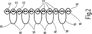
図2に示すように、横糸フィラメント12は一対の横糸フィラメントから構成されるか、もしくは複数のフィラメントから形成される。これは、ねじれフィラメント10にも当てはまる。さらにこれは、横断面図である図2に一対の横糸フィラメント12の上に、そして横糸フェラメント対12の下に交互に伸びていくことにより表されている。図にあるように、それぞれの機能糸又は毛糸16は、1つの横糸フィラメント対12をとばし、2つ後の横糸フィラメント対12に伸びていく。
As shown in FIG. 2, the
2つの図から見られるように、ベースファブリック14の下に伸びるために他のループ24は横糸フィラメント12に伸びる。そしてそれは、図1の基準点として見られ、前のループ22がベースファブリック14に位置する点から外側にねじれフィラメント10を2つ分と横糸フィラメント12を2つ分ずれた位置である。その結果、最初のタイプ22ともう一方のタイプ24のループはベースファブリック14に互いにずらして配置される。最初のタイプ22のループは本質的には閉じられたO型のループを形成する。そして他のタイプ24はV形状、U形状に構成される。ねじれフィラメント10の5つ毎に横糸フィラメント12の方向において、機能フィラメント16が繰り返される。さらに、フィラメントの組織は織物繊維としてもよいが、プラスチック材、ナイロン又はポリプロピレンとしてもよい。説明した本願発明に、少なくともファスナーの一部に金属ファイバー組織を使用する可能性はある。
As can be seen from the two figures, the
横糸フィラメント12のウエーブ形状は、剥離時の剥離方向の抵抗増加を可能とする。したがってファスナー解放において、同様に対応するフック材として作られる22、24のループオフセット形状も同様の効果を有する。これにより、ファスナーの留める力が増大し、その結果としての高い固定、剥離力を発揮する。
The wave shape of the
さらに、ファスナー形状を選択することによって、接着ファスナーを同じ力によりはがすことができるよう、接着力を調整することができる。 Furthermore, the adhesive force can be adjusted by selecting the fastener shape so that the adhesive fastener can be peeled off with the same force.
Claims (11)
Applications Claiming Priority (2)
| Application Number | Priority Date | Filing Date | Title |
|---|---|---|---|
| DE10240986A DE10240986B3 (en) | 2002-09-05 | 2002-09-05 | Flat adhesive closure part comprises detachable closure elements, a backing fabric made from warp thread and weft thread, and a functional thread partially interacting with the backing fabric |
| PCT/EP2003/007372 WO2004021823A1 (en) | 2002-09-05 | 2003-07-09 | Planar adhesive closure piece |
Publications (2)
| Publication Number | Publication Date |
|---|---|
| JP2005537833A JP2005537833A (en) | 2005-12-15 |
| JP4542428B2 true JP4542428B2 (en) | 2010-09-15 |
Family
ID=30128855
Family Applications (1)
| Application Number | Title | Priority Date | Filing Date |
|---|---|---|---|
| JP2004533248A Expired - Lifetime JP4542428B2 (en) | 2002-09-05 | 2003-07-09 | Face adhesive closure piece |
Country Status (7)
| Country | Link |
|---|---|
| US (1) | US7351464B2 (en) |
| EP (1) | EP1534096B1 (en) |
| JP (1) | JP4542428B2 (en) |
| AT (1) | ATE365477T1 (en) |
| DE (2) | DE10240986B3 (en) |
| ES (1) | ES2287560T3 (en) |
| WO (1) | WO2004021823A1 (en) |
Families Citing this family (15)
| Publication number | Priority date | Publication date | Assignee | Title |
|---|---|---|---|---|
| DE202006002409U1 (en) | 2006-01-18 | 2006-04-20 | Gottlieb Binder Gmbh & Co. Kg | Flame retardant closure |
| DE102006002339A1 (en) * | 2006-01-18 | 2007-07-19 | Gottlieb Binder Gmbh & Co. Kg | Flame retardant fastener for e.g. fastening wall panel to support structure, has fastener part with base fabric including carrier layer partially on rear side, where layer is formed with flame resistant medium or active extinguishing medium |
| DE102008048205A1 (en) | 2008-09-20 | 2010-04-01 | Gottlieb Binder Gmbh & Co. Kg | Process for the surface functionalization of an adhesive closure part and adhesive closure part produced by the process |
| DE102009021094A1 (en) | 2009-05-13 | 2010-11-18 | Gottlieb Binder Gmbh & Co. Kg | Mechanical adhesive closure part |
| DE102009032301A1 (en) | 2009-07-09 | 2011-01-13 | Gottlieb Binder Gmbh & Co. Kg | Fastener part |
| DE102013010085A1 (en) | 2013-06-10 | 2014-12-11 | Gottlieb Binder Gmbh & Co. Kg | Flat adhesive closure part and cleaning system with such a sheet-like adhesive closure part |
| DE102013022112A1 (en) | 2013-12-27 | 2015-07-02 | Gottlieb Binder Gmbh & Co. Kg | Flame retardant closure and flame-retardant finish or coating |
| DE102014003211A1 (en) | 2014-03-07 | 2015-09-10 | Gottlieb Binder Gmbh & Co. Kg | Joining method together with functional part usable therefor and flame retardant overall system produced thereafter |
| DE102017011244A1 (en) | 2017-12-06 | 2019-06-06 | Gottlieb Binder Gmbh & Co. Kg | Fastener system |
| FR3116419A1 (en) | 2020-11-23 | 2022-05-27 | Aplix | Improved retainer for protecting retainers |
| DE102021000393A1 (en) | 2021-01-27 | 2022-07-28 | Gottlieb Binder Gmbh & Co. Kg | Fastening device together with a method for producing such a fastening device and a fastening system manufactured with such a fastening device |
| DE102021003311A1 (en) | 2021-06-26 | 2022-12-29 | Gottlieb Binder Gmbh & Co. Kg | Process for manufacturing a touch-and-close fastener part |
| DE102021005460A1 (en) | 2021-11-04 | 2023-05-04 | Gottlieb Binder Gmbh & Co. Kg | connection system |
| DE102021006483A1 (en) | 2021-12-30 | 2023-07-06 | Gottlieb Binder Gmbh & Co. Kg | locking system |
| DE102022127854A1 (en) | 2022-10-24 | 2024-04-25 | Gottlieb Binder Gmbh & Co. Kg | Closure part |
Family Cites Families (6)
| Publication number | Priority date | Publication date | Assignee | Title |
|---|---|---|---|---|
| US5040275A (en) * | 1990-06-01 | 1991-08-20 | Minnesota Mining And Manufacturing Company | Strip material used for forming fasteners |
| JPH0652521U (en) * | 1992-12-28 | 1994-07-19 | 吉田工業株式会社 | Male fastening material for hook-and-loop fasteners with high-density hook pieces |
| JP2828593B2 (en) * | 1994-04-22 | 1998-11-25 | ワイケイケイ株式会社 | A hook-and-loop fastener having a thick base cloth |
| US6076238A (en) * | 1999-04-13 | 2000-06-20 | 3M Innovative Properties Company | Mechanical fastener |
| JP3626389B2 (en) * | 2000-02-29 | 2005-03-09 | Ykk株式会社 | Hook-and-loop fastener |
| JP3647357B2 (en) * | 2000-04-28 | 2005-05-11 | Ykk株式会社 | Hook-and-loop fastener |
-
2002
- 2002-09-05 DE DE10240986A patent/DE10240986B3/en not_active Withdrawn - After Issue
-
2003
- 2003-07-09 US US10/526,463 patent/US7351464B2/en not_active Expired - Lifetime
- 2003-07-09 DE DE50307576T patent/DE50307576D1/en not_active Expired - Lifetime
- 2003-07-09 EP EP03793616A patent/EP1534096B1/en not_active Expired - Lifetime
- 2003-07-09 ES ES03793616T patent/ES2287560T3/en not_active Expired - Lifetime
- 2003-07-09 JP JP2004533248A patent/JP4542428B2/en not_active Expired - Lifetime
- 2003-07-09 AT AT03793616T patent/ATE365477T1/en active
- 2003-07-09 WO PCT/EP2003/007372 patent/WO2004021823A1/en active IP Right Grant
Also Published As
| Publication number | Publication date |
|---|---|
| DE50307576D1 (en) | 2007-08-09 |
| ES2287560T3 (en) | 2007-12-16 |
| US20050268439A1 (en) | 2005-12-08 |
| WO2004021823A1 (en) | 2004-03-18 |
| JP2005537833A (en) | 2005-12-15 |
| EP1534096B1 (en) | 2007-06-27 |
| EP1534096A1 (en) | 2005-06-01 |
| ATE365477T1 (en) | 2007-07-15 |
| DE10240986B3 (en) | 2004-02-12 |
| US7351464B2 (en) | 2008-04-01 |
Similar Documents
| Publication | Publication Date | Title |
|---|---|---|
| JP4542428B2 (en) | Face adhesive closure piece | |
| CA1280581C (en) | Sheet material used to form portions of fasteners | |
| US4454183A (en) | Strip material with heat-formed hooked heads | |
| JP3505089B2 (en) | Fiber surface fastener | |
| US3748701A (en) | Adhesive element in cloth form | |
| US6546603B1 (en) | Woven hook and loop fastening | |
| US3833972A (en) | Self-adhering fastening filament | |
| EP3481246B1 (en) | Fastener tape | |
| EP1237434A2 (en) | Woven hook and loop fastening | |
| EP2792266B1 (en) | Loop surface fastener having excellent positioning function | |
| JP2006265782A (en) | Engaging filament nonwoven fabric | |
| MXPA02009704A (en) | Pre crimped tie components. | |
| JP3132775B2 (en) | Hook-loop mixed surface fastener and method of manufacturing the same | |
| JP2002360315A (en) | Knitted slide fastener | |
| GB2115481A (en) | Strip fastening material with heat-formed hooked heads | |
| JP6717448B2 (en) | Method for manufacturing surface fastener | |
| JP4108312B2 (en) | Hook and loop fastener with excellent engagement | |
| EP0226124B1 (en) | Mandrel for use with loom for forming loops of surface-type fasteners | |
| EP0058087B1 (en) | Weft insertion knitted secondary carpet backing and carpet structure | |
| US20240115013A1 (en) | Method for producing a touch-and-close fastener part | |
| JP2003221772A (en) | Nonwoven fabric for fastening use | |
| JP2019063198A (en) | Cloth-made hook-and-loop fastener | |
| JP2003038213A (en) | Filament non-woven fabric for detaining material of fastener | |
| EP0053348B1 (en) | Hooked fabric fastener tape | |
| JP3777551B2 (en) | Pin tenter slip-proof fabric |
Legal Events
| Date | Code | Title | Description |
|---|---|---|---|
| A621 | Written request for application examination |
Free format text: JAPANESE INTERMEDIATE CODE: A621 Effective date: 20060407 |
|
| A131 | Notification of reasons for refusal |
Free format text: JAPANESE INTERMEDIATE CODE: A131 Effective date: 20090929 |
|
| A601 | Written request for extension of time |
Free format text: JAPANESE INTERMEDIATE CODE: A601 Effective date: 20091224 |
|
| A602 | Written permission of extension of time |
Free format text: JAPANESE INTERMEDIATE CODE: A602 Effective date: 20100106 |
|
| A521 | Request for written amendment filed |
Free format text: JAPANESE INTERMEDIATE CODE: A523 Effective date: 20100319 |
|
| TRDD | Decision of grant or rejection written | ||
| A01 | Written decision to grant a patent or to grant a registration (utility model) |
Free format text: JAPANESE INTERMEDIATE CODE: A01 Effective date: 20100615 |
|
| A01 | Written decision to grant a patent or to grant a registration (utility model) |
Free format text: JAPANESE INTERMEDIATE CODE: A01 |
|
| A61 | First payment of annual fees (during grant procedure) |
Free format text: JAPANESE INTERMEDIATE CODE: A61 Effective date: 20100625 |
|
| R150 | Certificate of patent or registration of utility model |
Free format text: JAPANESE INTERMEDIATE CODE: R150 Ref document number: 4542428 Country of ref document: JP Free format text: JAPANESE INTERMEDIATE CODE: R150 |
|
| FPAY | Renewal fee payment (event date is renewal date of database) |
Free format text: PAYMENT UNTIL: 20130702 Year of fee payment: 3 |
|
| R250 | Receipt of annual fees |
Free format text: JAPANESE INTERMEDIATE CODE: R250 |
|
| R250 | Receipt of annual fees |
Free format text: JAPANESE INTERMEDIATE CODE: R250 |
|
| R250 | Receipt of annual fees |
Free format text: JAPANESE INTERMEDIATE CODE: R250 |
|
| R250 | Receipt of annual fees |
Free format text: JAPANESE INTERMEDIATE CODE: R250 |
|
| R250 | Receipt of annual fees |
Free format text: JAPANESE INTERMEDIATE CODE: R250 |
|
| R250 | Receipt of annual fees |
Free format text: JAPANESE INTERMEDIATE CODE: R250 |
|
| R250 | Receipt of annual fees |
Free format text: JAPANESE INTERMEDIATE CODE: R250 |
|
| R250 | Receipt of annual fees |
Free format text: JAPANESE INTERMEDIATE CODE: R250 |
|
| R250 | Receipt of annual fees |
Free format text: JAPANESE INTERMEDIATE CODE: R250 |
|
| R250 | Receipt of annual fees |
Free format text: JAPANESE INTERMEDIATE CODE: R250 |
|
| R250 | Receipt of annual fees |
Free format text: JAPANESE INTERMEDIATE CODE: R250 |
|
| EXPY | Cancellation because of completion of term |