EP1533954B1 - Procédé et système pour la détection d'un état de panne d'une unité de transmission - Google Patents
Procédé et système pour la détection d'un état de panne d'une unité de transmission Download PDFInfo
- Publication number
- EP1533954B1 EP1533954B1 EP04300801.0A EP04300801A EP1533954B1 EP 1533954 B1 EP1533954 B1 EP 1533954B1 EP 04300801 A EP04300801 A EP 04300801A EP 1533954 B1 EP1533954 B1 EP 1533954B1
- Authority
- EP
- European Patent Office
- Prior art keywords
- transmission unit
- counter
- datapath
- counter set
- specified
- Prior art date
- Legal status (The legal status is an assumption and is not a legal conclusion. Google has not performed a legal analysis and makes no representation as to the accuracy of the status listed.)
- Expired - Lifetime
Links
- 230000005540 biological transmission Effects 0.000 title claims description 550
- 238000000034 method Methods 0.000 title claims description 64
- 238000001514 detection method Methods 0.000 title description 21
- 238000011144 upstream manufacturing Methods 0.000 claims description 35
- 230000004044 response Effects 0.000 claims description 13
- 230000003213 activating effect Effects 0.000 claims description 11
- 230000008569 process Effects 0.000 claims description 11
- 230000001419 dependent effect Effects 0.000 claims description 5
- 230000000977 initiatory effect Effects 0.000 claims description 5
- 230000004913 activation Effects 0.000 description 26
- 238000010586 diagram Methods 0.000 description 8
- 238000003780 insertion Methods 0.000 description 7
- 230000037431 insertion Effects 0.000 description 7
- 238000012360 testing method Methods 0.000 description 7
- 230000001934 delay Effects 0.000 description 5
- 239000000872 buffer Substances 0.000 description 4
- 230000006870 function Effects 0.000 description 4
- 238000002955 isolation Methods 0.000 description 4
- 230000001360 synchronised effect Effects 0.000 description 4
- 230000008901 benefit Effects 0.000 description 2
- 230000006727 cell loss Effects 0.000 description 2
- 238000004891 communication Methods 0.000 description 2
- 239000004744 fabric Substances 0.000 description 2
- 238000012545 processing Methods 0.000 description 2
- 238000006467 substitution reaction Methods 0.000 description 2
- 230000002123 temporal effect Effects 0.000 description 2
- 230000002411 adverse Effects 0.000 description 1
- 230000008859 change Effects 0.000 description 1
- 238000013500 data storage Methods 0.000 description 1
- 238000013154 diagnostic monitoring Methods 0.000 description 1
- 238000007689 inspection Methods 0.000 description 1
- 230000000873 masking effect Effects 0.000 description 1
- 238000005259 measurement Methods 0.000 description 1
- 230000007246 mechanism Effects 0.000 description 1
- 230000002093 peripheral effect Effects 0.000 description 1
- 239000000126 substance Substances 0.000 description 1
- 238000012546 transfer Methods 0.000 description 1
- 230000007704 transition Effects 0.000 description 1
Images


Classifications
-
- H—ELECTRICITY
- H04—ELECTRIC COMMUNICATION TECHNIQUE
- H04L—TRANSMISSION OF DIGITAL INFORMATION, e.g. TELEGRAPHIC COMMUNICATION
- H04L12/00—Data switching networks
- H04L12/54—Store-and-forward switching systems
- H04L12/56—Packet switching systems
- H04L12/5601—Transfer mode dependent, e.g. ATM
-
- H—ELECTRICITY
- H04—ELECTRIC COMMUNICATION TECHNIQUE
- H04L—TRANSMISSION OF DIGITAL INFORMATION, e.g. TELEGRAPHIC COMMUNICATION
- H04L43/00—Arrangements for monitoring or testing data switching networks
- H04L43/08—Monitoring or testing based on specific metrics, e.g. QoS, energy consumption or environmental parameters
- H04L43/0823—Errors, e.g. transmission errors
- H04L43/0829—Packet loss
- H04L43/0835—One way packet loss
-
- H—ELECTRICITY
- H04—ELECTRIC COMMUNICATION TECHNIQUE
- H04L—TRANSMISSION OF DIGITAL INFORMATION, e.g. TELEGRAPHIC COMMUNICATION
- H04L12/00—Data switching networks
- H04L12/54—Store-and-forward switching systems
- H04L12/56—Packet switching systems
- H04L12/5601—Transfer mode dependent, e.g. ATM
- H04L2012/5625—Operations, administration and maintenance [OAM]
-
- H—ELECTRICITY
- H04—ELECTRIC COMMUNICATION TECHNIQUE
- H04L—TRANSMISSION OF DIGITAL INFORMATION, e.g. TELEGRAPHIC COMMUNICATION
- H04L12/00—Data switching networks
- H04L12/54—Store-and-forward switching systems
- H04L12/56—Packet switching systems
- H04L12/5601—Transfer mode dependent, e.g. ATM
- H04L2012/5638—Services, e.g. multimedia, GOS, QOS
- H04L2012/5646—Cell characteristics, e.g. loss, delay, jitter, sequence integrity
- H04L2012/5647—Cell loss
Definitions
- the present invention relates generally to communication networks, and more particularly to facilitating loss and fault detection of transmission units in communication networks.
- FRU field replaceable unit
- buffers and switch fabrics are part of the datapath through the switch.
- a first-in-first-out (FIFO) buffer to fail in a manner that causes the FIFO buffer to repeatedly transmit a particular ATM cell.
- FIFO first-in-first-out
- a fault condition in the buffers and switch fabrics to cause ATM cells to be lost as they traverse the datapath.
- a mechanism for detecting cell loss is not provided in the ATM protocol, it is difficult to determine that a fault exists that is causing the ATM cells to be lost.
- transmission unit loss/addition is much more difficult to identify than is detection of transmission unit corruption. This is because a corrupted transmission unit is typically available for inspection and analysis for showing such corruption. Detection of transmission unit loss/addition requires analysis of the transmission unit stream, rather than an individual transmission unit.
- a conventional solution for evaluating fault detection in an ATM datapath includes installing a test apparatus in the ATM datapath.
- the test apparatus includes counters that are inserted at ingress and egress ends of the ATM datapath for counting a number of ATM cells traversing these ends. After a predetermined interval of test ATM cell traffic, the test ATM cell traffic in the datapath is stopped, thus allowing the counters to settle. Once the counters have settled, the values of the counters are compared to determine if cell loss or cell addition has occurred.
- Document US 6 188 674 discloses a method for packet loss measurement in high-speed switches which is achieved by identifying traffic flows in the ingress side of switches, and measuring packets losses for the identifies flows on the egress side of the switches.
- Document US 6 141326 discloses an exchange that has units traversed by cells, such as a line interface unit, a cell multiplexer/demultiplexer unit and a cell switch unit, as well as a processor. Each cell traversing unit detects and counts passing cell and cell error on a per-connection basis, adds the counts, along with unit identification data, onto an intra-office cell and then transmits the cell.
- cells such as a line interface unit, a cell multiplexer/demultiplexer unit and a cell switch unit, as well as a processor.
- Each cell traversing unit detects and counts passing cell and cell error on a per-connection basis, adds the counts, along with unit identification data, onto an intra-office cell and then transmits the cell.
- a method for detecting a transmission unit fault condition is provided as defined in claim 1. Particular features of this method are provided as defined in claims 2 to 27.
- a network system for detecting a transmission unit fault condition is provided as defined in claim 28. Particular features of this network system are provided as defined in claims 29 to 32.
- FIG. 1 is a block diagram view depicting a first embodiment of a network system in accordance with the disclosures made herein.
- FIG. 2 is a timeline view depicting various intervals of time in accordance with embodiments of the disclosures made herein.
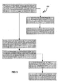
- FIG. 3 is a flow chart view depicting a method of facilitating fault detection in accordance with embodiments of the disclosures made herein.
- FIG. 4 is a block diagram view depicting an embodiment of a line card capable of tagging transmission units.
- FIG. 5 is a block diagram view depicting an embodiment of a line card capable of inserting a trigger transmission unit in a stream of transmission units.
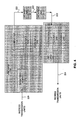
- FIG. 6 is a flow diagram view depicting a method 300 for facilitating fault detection via a line card capable of inserting a trigger transmission unit in a stream of transmission units.
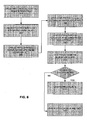
- FIG. 7 is a block diagram view depicting an embodiment of a network system having distributed transmission unit counter sets and datapath units.
- FIG. 8 is a block diagram depicting an embodiment of a network system having multiplexed ingress streams of transmission units.
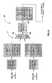
- FIG. 9 is a block diagram illustrating a network system 900 in accordance with at least one embodiment of the present invention.
- fault detection for transmission units (e.g., ATM cells, IP packets and the like) in data networks, telecommunication networks or other type of network system.
- Fault detection is defined herein to include loss of transmission units, unintentional insertion of transmission units and the like.
- transmission unit counter sets are positioned at various locations of a datapath for assessing the flow of transmission units through the datapath.
- An Asynchronous Transfer Mode (ATM) datapath is one example of a datapath in accordance with the disclosures made herein.
- Each counter set includes a plurality of counters capable of facilitating a respective transmission unit count.
- Each counter of a transmission unit counter set facilitates counting transmission units for a particular time interval.
- a fault condition is identified when a discrepancy is determined between the transmission unit counts at two or more of such various locations during an associated particular time interval.
- fault detection of transmission units may be facilitated without interrupting subscriber services on a datapath.
- the actual transmission units carrying subscriber content are used for facilitating fault detection rather than specially designated test transmission units.
- fault detection is facilitated in a real-time manner without interrupting subscriber services rather than in an off-line manner where subscriber services are suspended or otherwise altered. Accordingly, fault detection is facilitated such that a loss, insertion or other fault condition is capable of being identified and addressed proactively rather than reactively.
- FIG. 1 depicts a network system 10 including a plurality of datapath units 12 coupled in series in a datapath 14.
- the datapath 14 and the term 'datapath' referred to elsewhere herein refer to a transmission path over which transmission units travel between two or more adjacent transmission unit counter sets.
- a field replaceable unit (FRU) is an example of the datapath unit 12.
- An FRU may include any unit of a system that is readily replaceable, for example, replaceable without having to replace a larger portion of the system or return a larger portion of the system to a vendor or manufacturer for service or replacement.
- the network system 10 is depicted in FIG. 1 to include two datapath units 12, it is contemplated herein that the network system 10 may include more then 2 datapath units 12 or only one datapath unit 12.
- a counter activation module 16 and a first transmission unit counter set 18 are coupled in the datapath 14 at a first counting location L1 of the datapath 14.
- the first transmission counter set 18 is coupled between the plurality of datapath units 12 and the counter activation module 16.
- the first transmission unit counter set 18 includes a first counter 20 and a second counter 22.
- a second transmission unit counter set 24 is coupled at a second counting location L2 of the datapath.
- the second transmission unit counter set 24 includes a first counter 26 and a second counter 28. Relative to a flow direction F of a stream of transmission units being assessed, the first counting location L1 is upstream of the plurality of datapath units 12 and the second counting location L2 is downstream of the plurality of datapath units 12.
- transmission units are transmitted over the datapath 14 toward the datapath units 12 (i.e., ingress datapath transmission units) via the counter activation module 16.
- the counter activation module 16 dictates which counter of each one of the first and the second transmission unit counter sets (18, 24) is actively counting the transmission units which are emitted by the counter activation module (16) during a given period of time.
- the intent is to determine a count difference between the number of ingress transmission units and the number of transmission units exiting the datapath 14 (i.e., egress datapath transmission units) at the second counting location L2 that are counted during given counting and settling intervals.
- ingress datapath transmission units and egress datapath transmission units refer to transmission units transmitted over a datapath between two or more adjacent transmission unit counter sets rather than transmission units entering and exiting a datapath at a particular counting location. Accordingly, a transmission unit count made at an upstream transmission unit counter set is sometimes referred to herein as an ingress datapath transmission unit count and a transmission unit count made at a downstream transmission unit counter set is sometimes referred to herein as an egress datapath transmission unit count.
- the counter activation module 16 may function to designate (e.g., tag) transmission units in a particular manner such that a corresponding one of the counters of each transmission unit counter set (18, 24) counts only the designated transmission units or to issue an activation (e.g., trigger) transmission unit that activates a corresponding one of the counters of each transmission unit counter set.
- the first counters (20, 26) of each of the first and the second transmission unit counter sets (18, 24, respectively) both actively count transmission units emitted by the counter activation module (16) during a first specified counting interval 30 ( FIG. 2 ).
- the second counter (22, 28) of each the first and the second transmission unit counter sets (18, 24, respectively) both actively count transmission units emitted by the counter activation module (16) during a second specified counting interval 32 ( FIG. 2 ). As shown in FIG. 2 , the second specified counting interval 32 follows the first specified counting interval 30.
- the first counter (20, 26) of the first and the second transmission unit counter sets (18, 24, respectively) may continue counting even after the respective specified counting interval elapses.
- intervals of time are illustrated with respect to time axis 44.
- the first counters of each of the plurality of transmission unit counter sets (18, 24) are actively counting transmission units emitted by the counter activation module (16) during the first specified counting interval 30.
- the first specified counting interval 30 elapses and the second specified counting interval 32 begins.
- a plurality of propagation delays (36, 38, 40) exists in association with transmission of transmission units from the first transmission unit counting set 18 through the plurality of datapath units 12 to the second transmission unit counting set 24. Accordingly, a first specified settling interval 42 may be initiated jointly with the second specified counting interval 32. The duration of the first specified settling interval 42 is equal to or greater than the sum of the plurality of propagation delays (36, 38, 40). Effectively, time must be provided for the last transmission unit of the first specified counting interval 30 to be received and counted at the second transmission unit counter set (24).
- the magnitude of a total propagation delay may be dependent upon a duration of time during which transmission units are transmitted via the datapath and/or a temporal alignment of said transmission units being transmitted via the datapath.
- the latency of one or more datapath units may change as a function of a temporal alignment of the transmission units passing through it, thereby affecting the total propagation delay.
- first specified settling interval 42 with second specified counting interval 32 is a function of the durations of propagation delays 36, 38, and 40, as well as the scheduling of the beginning of the second specified counting interval 32 relative to the end of first specified counting interval 30. For example, if the second specified counting interval 32 begins at the beginning of first specified settling interval 42, then the first specified settling interval 42 will overlap entirely with a beginning portion of the second specified counting interval 32. As another example, if the second specified counting interval 32 begins after the beginning of the first specified settling interval 42, the amount of overlap may be reduced.
- a second specified settling interval (not shown) is associated with the second specified counting interval 32 in a similar manner as the first specified settling interval 42 is associated with the first specified counting interval 30.
- An advantage of the use of a plurality of counters in each one of the transmission unit counter sets (18, 24) is that fault detection may be facilitated in a substantially continuous manner. For example, a first transmission unit settling process being facilitated during a first specified settling interval by the first counter of each of the first and the second transmission unit counter sets (18, 24) is able to proceed to a point of completion, in view of finite propagation delays, while a second transmission unit counting process is being facilitated by the second counter of each of the first and the second transmission unit counter sets (18, 24). Such is the case when the first specified settling interval 42 overlaps with the second specified counting interval.
- transmission units associated with the second specified counting interval 32 may continue to be counted by the second counter (22, 28) of the first and second transmission unit counter sets (18, 24) even though a first transmission unit settling process facilitated by the first counter (20, 26) of each of the first and the second transmission unit counter sets (18, 24) has been initiated.
- FIG. 3 depicts a method 100 of facilitating fault detection in accordance with embodiments of the disclosures made herein.
- the method 100 is capable of being carried out via systems in accordance with embodiments of the disclosures made herein.
- the method 100 includes a first counting process 105 for facilitating a counting operation of first transmission units (i.e., transmission units which are emitted by the counter activation module (16) during the first specified counting interval (30)) at a first counter of each one of a plurality of transmission unit counter sets.
- the plurality of transmission unit counter sets is distributed between two adjacent counting locations of the datapath. Each of these counting operations returns a respective first datapath transmission unit count associated with a corresponding one of the counting locations.
- the first specified counting interval is defined herein as a duration of time in which the counter activation module (16) emits transmission units which are then counted by the first counter of each one of the plurality of transmission unit counter sets (i.e., counting for determining the respective first datapath transmission unit count).
- An operation 110 is performed for determining a difference between the first transmission unit counts of the adjacent counting locations.
- an operation 115 is performed for indicating an operating condition corresponding to the first transmission unit counting process. Examples of the operating condition include a fault condition when transmission unit counts are not equal and a proper operating condition when transmission unit counts are equal.
- an operation 120 is performed for activating a next counter in each of the transmission unit counter sets (e.g., the second counter).
- a second counting process 125 is performed for facilitating a counting operation of second transmission units (e.g., transmission units which are emitted by the counter activation module (16) during the second specified counting interval (34)) at a second counter of each one of a plurality of transmission unit counter sets during a second specified counting interval.
- Each second transmission unit counting operation returns a respective second transmission unit count.
- An operation 130 is performed for determining a difference between the second transmission unit counts of the adjacent counting locations.
- an operation 135 is performed for indicating an operating condition corresponding to the second transmission unit counting process.
- transmission units may be entering and leaving the data stream within a datapath. Accordingly, the difference between transmission unit counts on either side of the datapath may be the difference between the number of transmission units entering the datapath and exiting the datapath. To prevent this condition from masking true fault conditions, those transmission units which intentionally enter or exit the data stream within a datapath may be counted and taken into consideration when indicating the operating condition in operation 135.
- a counter activation module (e.g., the counter activation module 16) may function to designate (e.g., tag) transmission units in a particular manner such that a corresponding counter of a transmission unit counter set counts only the designated transmission units, or to issue an activation (e.g., trigger) transmission unit that activates a corresponding counter of a transmission unit counter set.
- a line card 200 capable of tagging transmission units.
- a line card 250 capable of inserting a trigger transmission unit in a stream of transmission units. Note that the depiction of certain elements of FIG. 4 as being within line card 200 or line card 226 or of certain elements of FIG.
- line card 250 or line card 294 is intended to be exemplary. Such elements need not be within such line cards and/or other elements may be included within such line cards. In fact, line cards are not a required element, and some embodiments of the invention may be practiced without line cards. Other configurations are also possible, for example, in some embodiments, some or all of the elements depicted as being in line cards 200 and 226 may be included within the same line card or some or all of the elements depicted as being in line cards 250 and 294 may be included within the same line card.
- the line card 200 depicted in FIG. 4 includes a transmission unit tagging module 202 and a transmission unit (TU) counter set 204 coupled to the transmission unit tagging module 202.
- the transmission unit counter set 204 includes a first counter 206 and a second counter 208.
- a line card 200 is coupled in a datapath 222 at an upstream counting location and a line card 226 is coupled in the datapath 222 at a downstream counting location.
- the line card 200 at the upstream counting location receives ingress transmission units at input 220.
- the line card 226 at the downstream counting location provides egress transmission units at output 224.
- Datapath units 210 and 212 are coupled in datapath 222 between line card 200 and line card 226.
- Line card 226 comprises TU counter set 214, which comprises counter A 216 and counter B 218. Being downstream, line card 226 need not include a TU tagging module although it may include one that merely allows transmission units tagged by TU tagging module 202 to pass.
- the transmission unit tagging module 202 of the line card 200 at the upstream counting location facilitates tagging transmission units received at input 220 as Type A transmission units (i.e., first designated transmission units) during a first specified counting interval.
- An embodiment of tagging includes setting at least one bit of each transmission unit to a first prescribed setting. The at least one bit is preferably located similarly within each one of the transmission units.
- the transmission unit tagging module discontinues tagging transmission units as Type A transmission units and begins tagging the transmission units as Type B transmission units.
- the second counter 208 of the line card 200 at the upstream counting location and the second counter 218 of the line card 226 at the downstream counting position count Type B transmission units when processing transmission units tagged by the upstream tagging module 202 during the second specified counting interval.
- counting of Type A transmission units is allowed to settle in view of propagation delay during a first specified settling interval, followed by a comparison of a transmission unit count of Type A transmission units made by the first counter 206 of the line card 200 at the upstream position and a transmission unit count of Type A transmission units made by the first counter 216 of the line card 226 at the downstream counting location.
- the line card 250 depicted in FIG. 5 comprises a trigger transmission unit insertion module 255, an active counter indication module 260 and a transmission unit counter set 265.
- the transmission unit counter set 265 is coupled to the trigger transmission unit insertion module 255 and to the active counter indication module 260.
- the transmission unit counter set comprises a first counter 270 and a second counter 275.
- the counter indicator 260 facilitates indicating which one of the counters (270, 275) of the transmission unit counter set 265 is actively counting the designated transmission units during a particular specified counting interval.
- the line card 294 depicted in FIG. 5 comprises a transmission unit counter set 284 and a counter indicator 290.
- Transmission unit counter set 284 comprises a counter A 286 and a counter B 288.
- line card 294 may but need not, comprise a trigger TU insertion module.
- a line card 250 is coupled in a datapath 292 at an upstream counting location and a line card 294 is coupled in the data path 292 at a downstream counting location.
- Line card 250 receives ingress transmission units at input 291 and outputs transmission units to datapath 292.
- Line card 294 receives transmission units from datapath 292 and provides egress transmission units at output 293.
- Datapath units 280 and 282 are in datapath 292 between line card 250 and line card 294.
- a method 300 for facilitating fault detection comprises an operation 302 for inserting a first trigger transmission unit in a stream of transmission units for initiating a first specified counting interval, performed by the trigger transmission unit insertion module 255 of the line card 250 at the upstream counting location.
- an operation 306 is performed for adjusting the counter indicator 260 to a state indicating that the first counter 270 of the line card 250 at the upstream counting position is actively counting received transmission units and the second counter 275 of the line card 250 at the upstream counting position is not counting received transmission units.
- an operation 310 is performed for adjusting the counter indicator 290 at the downstream counting location to a state indicating that the first counter 286 of the line card 294 at the downstream counting position is actively counting received transmission units, and the second counter 288 of the line card 294 at the downstream counting position is not counting received transmission units.
- the trigger transmission unit insertion module 255 performs an operation (not shown) for inserting a second trigger transmission unit in a stream of transmission units for initiating a second specified counting interval after the first specified counting interval elapses.
- an operation (not shown) is performed for adjusting the active counter indication module 260 to a second state indicating that the second counter 275 is actively counting received transmission units and the first counter 270 is not counting received transmission units.
- an operation is performed for adjusting the active counter indication module 290 to a second state indicating that the second counter 288 is actively counting received transmission units and the first counter 286 is not counting received transmission units.
- the second counter 275 of the line card 250 at the upstream counting location and the second counter 288 of the line card 294 at the downstream counting location actively count transmission units and the first counter 270 of the line card 250 at the upstream counting location and the first counter 286 of the line card 294 at the downstream counting location stop counting transmission units.
- an operation 312 Prior to comparing the transmission unit count made by the first counter 270 at the upstream counting location with the transmission unit count made by the first counter 286 at the downstream counting location, an operation 312 is performed for verifying that the counter indicator 260 at the upstream counting location is synchronized with the counter indicator 290 at the downstream counting location.
- an operation 314 is performed for comparing the transmission unit count made by the first counter 270 at the upstream counting location with the transmission unit count made by the first counter 286 at the downstream counting location, thus enabling a present operating condition to be indicated.
- the preceding steps may be repeated so as to repeat the method, or the method may be discontinued.
- an operation 316 is performed for repeating or discontinuing the method.
- the first counter 286 of the line card 294 at the downstream counting location continues to count first designated transmission units in view of propagation delay.
- a series of operations similar to the operations 304 through 316 is performed in association with the transmission unit counts for indicating any fault condition associated therewith.
- a network system 400 comprises a first datapath unit 405 coupled in a datapath 430 between a first transmission unit counter set 410 and a second transmission unit counter set 415.
- the network system 400 further comprises a second datapath unit 420 coupled in the datapath 430 between the second transmission unit counter set 415 and a third transmission unit counter set 425.
- the position of the first transmission unit counter set 410 defines a first counting location
- the position of the second transmission unit counter set 415 defines a second counting location
- the position of the third transmission unit counter set 425 defines a third counting location.
- An arrangement as depicted in FIG. 7 is intended to increase the resolution of fault isolation to a single datapath unit.
- the operation of the network system 400 is similar to that of the network system 10 depicted in FIG. 1 , with the exception that transmission unit counts made at each end of one of the datapath units (405, 420) are compared to each other. In response to difference being identified, the difference indicates that a fault condition exists in a particular datapath unit. Accordingly, when the first and the second datapath units (405, 420) are field replaceable units (FRU), a fault condition may be remedied by replacing the appropriate FRU. In the network system 10 depicted in FIG. 1 , a fault condition is not capable of being isolated to a particular one of the plurality of datapath units 12.
- FRU field replaceable units
- At least one method may be performed to provide identification of faulty datapath units more particularly.
- a method may comprise a step of performing a first datapath intermediary transmission unit counting operation during a duration consisting of a first specified counting interval 30 and a first specified settling interval 42. That operation may be performed at a first counter of a third transmission unit counter set 415 in a datapath 430 and may serve to determine a first datapath intermediary transmission unit count.
- the third transmission unit counter set 415 is situated between a first transmission unit counter set 410 and a second transmission unit counter set 425 along the datapath 430.
- Localized identification of a fault in the datapath 430 may be achieved by comparing the first datapath intermediary transmission unit count to the first datapath ingress transmission unit count obtained from the first transmission unit counter set 410 to identify a first fault status pertaining to a first portion of the datapath 430 between the first transmission unit counter set 410 and the third transmission unit counter set 415.
- such localized identification of a fault may be achieved by comparing the first datapath egress transmission unit count obtained from the second transmission unit counter set 425 to the first datapath intermediary transmission unit count to identify a second fault status pertaining to a second portion of the datapath 430 between the third transmission unit counter set 415 and the second transmission unit counter set 425.
- Such a method may be used to divide a datapath into as many segments as desired to obtain any level of granularity of localized identification of faults as may be desired.
- the network system 400 of FIG. 7 may be practiced with as many instances of transmission unit counter set 415 inserted in datapath 430 as may be desired and may include any number of datapath units, such as datapath units 405 and 420.
- a network system 500 includes a first transmission unit counter set 502 and a second transmission unit counter set 504 coupled in parallel in a datapath 506 via a multiplexing module 508.
- a datapath unit 510 is coupled between the multiplexing module 508 and a third transmission unit counter set 512.
- the first transmission unit counter set 502 facilitates a transmission unit count for a first stream of ingress transmission units (i.e., flow 1) and the second transmission unit counter set 504 facilitates a transmission unit count for a second stream of ingress transmission units (i.e., flow 2).
- the multiplexing module 508 multiplexes the flow (i.e., flow 1) associated with the first transmission unit counter set 502 and the flow (i.e., flow 2) associated with the second transmission unit counter set.
- the third transmission unit counter set 512 facilitates a transmission unit count for the combined flow (i.e., flow 1 + flow 2) of the first and the second transmission unit counter sets (502, 504, respectively). It is contemplated herein that additional transmission unit counter sets and datapath units may be utilized in the network system 500 in a similar manner as depicted in FIG. 7 for improving fault isolation capabilities.
- a first counter activation module 514 (e.g., a first cell tagging device) is coupled to the first transmission unit counting set 502 and a second counter activation module 516 (e.g., a second cell tagging device) is coupled to the second transmission unit counting set 504.
- the first and the second counter activation modules (514, 516) operate in unison to determine which one of a plurality of counters at each of the transmission unit counter sets (502, 504, 512) are actively counting designated transmission units. It should be understood that the first and the second counter activation modules (514, 516) need not be synchronized precisely with each other.
- At least one method may be performed in a network system comprising multiple ingress paths.
- a method may be practiced wherein determining the first datapath ingress transmission unit count is further performed at a third counting location, such as a counting location along a path carrying a flow of data to be merged into the datapath, and is further facilitated by a first counter of a transmission unit counter set at the third counting location.
- the first datapath ingress transmission unit count may be obtained based on counts performed by multiple counters at different locations counting ingress transmission units.
- FIG. 9 is a block diagram illustrating a network system 900 in accordance with at least one embodiment of the present invention.
- Network system 900 comprises a counter activation module 901, a transmission unit counter set 902, a splitter 903, datapath units 904 and 905, and transmission unit counter sets 906 and 907.
- Inbound transmission unit flow 908, which comprises a first flow and a second flow, is provided to counter activation module 901 and passes to transmission unit counter set 902.
- Transmission unit counter set 902 comprises a counter A 914 and a counter B 915.
- the transmission unit flow 909 continues to splitter 903, which splits the transmission unit flow 909 into the first flow 910 and the second flow 911.
- the first flow 910 is provided to datapath unit 904 and continues to transmission unit counter set 906.
- the second flow 911 is provided to datapath unit 905 and continues to transmission unit counter set 907.
- Transmission unit counter set 906 comprises a counter A 916 and a counter B 917.
- Transmission unit counter set 907 comprises a counter A 918 and a counter B 919.
- Transmission unit counter set 906 provides a first outbound flow 912.
- Transmission unit counter set 907 provides a second outbound flow 913.
- Counter activation module 901 which may be co-located with transmission unit counter set 902 or may be present anywhere upstream of transmission unit counter set 902, provides an indication of transmission units being designated to be counted by a correspondingly designated counter of transmission unit counter sets, such as transmission unit counter sets 902, 906, and 907.
- counter activation module may provide an indication of transmission units being designated to be counted by the counters A or counters B of transmission unit counter sets 902, 906, and 907.
- counter activation module 901 may tag transmission units with such an indication, which may, for example, take the form of marking at least one bit within or in proximity to a transmission unit with a value and, as a more particular example, with such at least one bit having a similar position relative to the transmission unit for each such indication provided.
- counter activation module 901 may provide at least one trigger indication among the transmission units to indicate a transition from designation of transmission units to be counted by one counter to designation of transmission units to be counted by another counter of transmission unit counter sets.
- Splitter 903 may route transmission units among first flow 910 and second flow 911 according to some criteria such that a transmission unit may be routed to first flow 910 but not second flow 911 or to second flow 911 but not first flow 910, or splitter 903 may provide all transmission units of transmission unit flow 909 to both of first flow 910 and second flow 911.
- splitter 903 may receive more than one inbound flow. In such a case, each inbound flow is preferably provided with its own transmission unit counter set.
- splitter 903 may provide more than two outbound flows. In such a case, each outbound flow is preferably provided with its own transmission unit counter set.
- datapath units 904 and 905 are illustrated as being located between splitter 903 and transmission unit counter sets 906 and 907, it should be understood that one or more datapath units may be located between transmission unit counter set 902 and splitter 903.
- one or more datapath units may be located between transmission unit counter set 902 and splitter 903 in addition to datapath units 904 and 905 or in substitution of either or both of datapath units 904 and 905.
- additional datapath units may be provided between splitter 903 and either or both of transmission unit counter sets 906 and 907.
- one or more transmission unit counter sets and/or one or more datapath units may be integrated into splitter 903 in addition to or in substitution of any other transmission unit counter sets and/or datapath units in the system.
- At least one method may be practiced in a network system in which a datapath is split into multiple flows of data.
- a method may be practiced by performing a first datapath second egress (i.e., first transmission units at a second egress path) transmission unit counting operation during the first specified counting interval 30 and during the first specified settling interval 42 at a first counter 918 of a third transmission unit counter set 907 in the datapath, wherein a first datapath second egress transmission unit count is determined, the third transmission unit counter set 907 being situated along a path 911 branching from the datapath 909 between the first transmission unit counter set 902 and the second transmission unit counter set 906.
- Such a method may be practiced wherein identical transmission units are provided to the second transmission unit counter set 906 and the third transmission unit counter set 907 and wherein indicating a fault condition associated with the first specified counting interval 30 alternatively occurs when a difference is determined between the first datapath ingress transmission unit count and the first datapath second egress transmission unit count after the first specified settling interval 42 elapses, as well as when a difference is determined between the first datapath ingress transmission unit count and the first datapath egress transmission unit count after the first specified settling interval 42 elapses.
- Another example of a method may be performed when a datapath is split into two mutually exclusive flows of data. Such a method may be practiced wherein performing a first datapath egress transmission unit counting operation is further performed at a first counter of a third transmission unit counter set, the third transmission unit counter set being situated along a path branching from the datapath between the first transmission unit counter set and the second transmission unit counter set, wherein the first datapath egress transmission unit count is further determined according to a sum of a first portion of transmission units counted at the first transmission unit counter set and a second portion of transmission units counted at the third transmission unit counter set.
- a method may be practiced wherein determining the first datapath egress transmission unit count is further performed at a third counting location, such as a counting location along a path branching from a datapath and is further facilitated by a first counter of a transmission unit counter set at the third counting location.
- the first datapath egress transmission unit count may be obtained based on counts performed by multiple counters at different locations counting egress transmission units.
- a data processor program controls at least a portion of the methods, processes, and/or operations associated with facilitating fault detection in a datapath of a network system. Accordingly, the data processor program controls at least a portion of the operations necessary to facilitate fault detection in a manner consistent with the disclosures made herein.
- the term data processor program is defined herein to refer to computer software, data processor algorithms, or any other type of instruction code capable of controlling operations associated with a data processor.
- a microprocessor, microcontroller, microcomputer, digital signal processor, state machine, logic circuitry, and/or any device that manipulates digital information based on operational instruction or in a predefined manner are examples of a data processor.
- a data processor program in accordance with an embodiment of the disclosures made herein is processable by a data processor of an active and/or inactive routing module of a network element.
- a copy of the data processor program may be resident on each of the routing elements in a network element.
- each copy of the data processor program may be accessible by a data processor of the respective routing module from a memory apparatus of the respective routing module (e.g., RAM, ROM, virtual memory, hard drive memory, etc.) or from a peripheral apparatus such as a diskette, a compact disk, an external data storage device, or the like.
- a data processor program accessible from an apparatus by a data processor is defined herein as a data processor program product. It is contemplated herein that the data processor program product may comprise more than one data processor program each accessible from respective apparatuses. It is further contemplated herein that each one of a plurality of data processor programs may be accessed by a different respective one of a plurality of data processors. For example, a first data processor and a second data processor (e.g., of a leaf node and a root note), respectively, may access a first data processor program and a second data processor program, respectively, from a first apparatus and a second apparatus (e.g., a first memory device and a second memory device), respectively.
- a first data processor and a second data processor e.g., of a leaf node and a root note
- the system may be configured to designate a first number of transmission units or transmission units emitted during a first period of time to be counted by the first counter and a second number of transmission units or transmission units emitted during a second period of time to be counted by the second counter.
- Such a process may be terminated after some amount of time or continued indefinitely, for example, by continuing to alternate between counting using the first counter and counting using the second counter.
- the system may be configured to designate a first number of transmission units or transmission units emitted into the system during a first period of time to be counted by the first counter and subsequent numbers of transmission units or transmission units emitted into the system during subsequent periods of time to be counted by counters other than the first counter in any pattern or sequence.
- Such a process may be terminated after some amount of time or continued indefinitely, for example, by changing counters after all transmission units emitted into the system during each period of time have passed such counters.
- the numbers of transmission units designated to be counted by each counter may be similar or different and/or the durations of periods of time during which transmission units are designated to be counted by respective counters may be similar or different.
- Modules are defined herein to include hardware, software and/or firmware components. Hardware, software and/or firmware for one module may jointly and/or individually comprise respective and appropriate portions all or part of hardware, software, and/or firmware of one or more other modules.
Landscapes
- Engineering & Computer Science (AREA)
- Computer Networks & Wireless Communication (AREA)
- Signal Processing (AREA)
- Environmental & Geological Engineering (AREA)
- Data Exchanges In Wide-Area Networks (AREA)
- Maintenance And Management Of Digital Transmission (AREA)
Claims (32)
- Procédé de détection d'une condition de défaut d'unité de transmission, comprenant les étapes suivantes :exécuter une première opération de comptage d'unités de transmission d'entrée de chemin de données pendant une première durée constituée par un premier intervalle de comptage spécifié (30) et un premier intervalle de stabilisation spécifié (42) après que le premier intervalle de comptage spécifié (30) s'est écoulé, sur un premier compteur (20) d'un premier ensemble de compteurs d'unités de transmission (18) dans un chemin de données (14) en un emplacement de comptage en amont (L1) où les unités de transmission d'entrée sont reçues, dans lequel un premier comptage d'unités de transmission d'entrée de chemin de données est déterminé ;exécuter une première opération de comptage d'unités de transmission de sortie de chemin de données pendant la première durée sur un premier compteur (26) d'un deuxième ensemble de compteurs d'unités de transmission (24) dans le chemin de données (14) en un emplacement de comptage en aval (L2) où les unités de transmission de sortie sont produites, dans lequel un premier comptage d'unités de transmission de sortie de chemin de données est déterminé ;dans lequel le premier intervalle de stabilisation spécifié (42) dépend d'un retard de propagation dans le chemin de données (14) entre le premier compteur (20) du premier ensemble de compteurs d'unités de transmission (18) et le premier compteur (26) du deuxième ensemble de compteurs d'unités de transmission (24),indiquer une condition de défaut associée au premier intervalle de comptage spécifié (30) lorsqu'une différence est déterminée entre le premier comptage d'unités de transmission d'entrée de chemin de données et le premier comptage d'unités de transmission de sortie de chemin de données après que le premier intervalle de stabilisation spécifié (42) s'est écoulé,initier un second intervalle de comptage spécifié (32) après que le premier intervalle de comptage spécifié (30) s'est écoulé ;exécuter une seconde opération de comptage d'unités de transmission d'entrée de chemin de données, d'unités de transmission désignées pendant le second intervalle de comptage spécifié (32), sur un second compteur (22) du premier ensemble de compteurs d'unités de transmission (18) dans le chemin de données (14), dans lequel un second comptage d'unités de transmission d'entrée de chemin de données est déterminé ;exécuter une seconde opération de comptage d'unités de transmission de sortie de chemin de données, pendant une seconde durée constituée par le second intervalle de comptage spécifié (32) et un second intervalle de stabilisation spécifié après que le second intervalle de comptage (32) s'est écoulé, sur un second compteur (28) du deuxième ensemble de compteurs d'unités de transmission (24) dans le chemin de données (14),dans lequel le second intervalle de stabilisation spécifié dépend d'un retard de propagation dans le chemin de données (14) entre le second compteur (22) du premier ensemble de compteurs d'unités de transmission (18) et le second compteur (28) du deuxième ensemble de compteurs d'unités de transmission (24), et dans lequel un second comptage d'unités de transmission de sortie de chemin de données est déterminé ; etindiquer une condition de défaut associée au second intervalle de comptage spécifié (32) lorsqu'une différence est déterminée entre le second comptage d'unités de transmission d'entrée de chemin de données et le second comptage d'unités de transmission de sortie de chemin de données après que le second intervalle de stabilisation spécifié s'est écoulé.
- Procédé selon la revendication 1, dans lequel le premier intervalle de comptage spécifié (30) et le premier intervalle de stabilisation spécifié (42) sont chacun des intervalles temporels prescrits respectifs.
- Procédé selon la revendication 1, comprenant en outre les étapes suivantes :insérer une première unité de transmission de déclenchement en amont du premier ensemble de compteurs d'unités de transmission (18) afin d'activer le premier compteur (20) du premier ensemble de compteurs d'unités de transmission et le premier compteur (26) du deuxième ensemble de compteurs d'unités de transmission (24) pendant le premier intervalle de comptage spécifié (30) ; etconfirmer que la première unité de transmission de déclenchement est reçue par le premier ensemble de compteurs d'unités de transmission (18) et par le deuxième ensemble de compteurs d'unités de transmission (24) avant d'indiquer la condition de défaut associée au premier intervalle de comptage spécifié (30).
- Procédé selon la revendication 3, comprenant en outre les étapes suivantes :régler un indicateur de compteur associé au premier ensemble de compteurs d'unités de transmission (18) dans un état indiquant que le premier compteur (20) du premier ensemble de compteurs d'unités de transmission est actif en réponse à la réception de la première unité de transmission de déclenchement par le premier ensemble de compteurs d'unités de transmission (18) ;régler un indicateur de compteur associé au deuxième ensemble de compteurs d'unités de transmission (24) dans un état indiquant que le premier compteur (26) du deuxième ensemble de compteurs d'unités de transmission est actif en réponse à la réception de la première unité de transmission de déclenchement par le deuxième ensemble de compteurs d'unités de transmission (24) ; etdans lequel la confirmation comprend la vérification des états de l'indicateur de compteur associé au premier ensemble de compteurs d'unités de transmission (18) et de l'indicateur de compteur associé au deuxième ensemble de compteurs d'unités de transmission (24) avant d'indiquer la condition de défaut associée au premier intervalle de comptage spécifié (30).
- Procédé selon la revendication 1, comprenant en outre les étapes suivantes :insérer une première unité de transmission de déclenchement en amont du premier ensemble de compteurs d'unités de transmission (18) afin d'activer le premier compteur (20) du premier ensemble de compteurs d'unités de transmission et le premier compteur (26) du deuxième ensemble de compteurs d'unités de transmission (24) pendant le premier intervalle de comptage spécifié (30),insérer une seconde unité de transmission de déclenchement en amont du premier ensemble de compteurs d'unités de transmission (18) afin d'activer un second compteur (22) du premier ensemble de compteurs d'unités de transmission (18) et un second compteur (28) du deuxième ensemble de compteurs d'unités de transmission (24) pendant le second intervalle de comptage spécifié (32) à la suite du premier intervalle de comptage spécifié (30) ; etconfirmer que la seconde unité de transmission de déclenchement est reçue par le premier ensemble de compteurs d'unités de transmission (18) et par le deuxième ensemble de compteurs d'unités de transmission (24) avant d'indiquer la condition de défaut associée au premier intervalle de comptage spécifié (30).
- Procédé selon la revendication 1, dans lequel l'indication de la condition de défaut est exécutée après la confirmation qu'une première unité de transmission de déclenchement a été reçue par le premier ensemble de compteurs d'unités de transmission (18) et par le deuxième ensemble de compteurs d'unités de transmission (24).
- Procédé selon la revendication 1, dans lequel l'indication de la condition de défaut est exécutée après la confirmation qu'une seconde unité de transmission de déclenchement, dont la transmission se produit après la transmission d'une première unité de transmission de déclenchement, a été reçue par le premier ensemble de compteurs d'unités de transmission (18) et par le deuxième ensemble de compteurs d'unités de transmission (24).
- Procédé selon la revendication 1, dans lequel :l'exécution de la première opération de comptage d'unités de transmission d'entrée de chemin de données comprend l'étiquetage d'unités de transmission reçues sur un premier emplacement de désignation d'unité de transmission pendant le premier intervalle de comptage spécifié (30) comme premières unités de transmission désignées et le comptage desdites premières unités de transmission désignées reçues sur le premier compteur (20) du premier ensemble de compteurs d'unités de transmission (18) ; etl'exécution de la première opération de comptage d'unités de transmission de sortie de chemin de données comprend le comptage desdites premières unités de transmission désignées reçues sur le premier compteur (26) du deuxième ensemble de compteurs d'unités de transmission (24) pendant le premier intervalle de comptage spécifié (30) et pendant le premier intervalle de stabilisation spécifié (42).
- Procédé selon la revendication 8, dans lequel l'étiquetage desdites unités de transmission comprend le réglage d'au moins un bit de chacune desdites unités de transmission sur un réglage prescrit.
- Procédé selon la revendication 9, dans lequel ledit au moins un bit est placé de façon similaire dans chacune desdites unités de transmission.
- Procédé selon la revendication 1, dans lequel l'indication de la condition de défaut associée au premier intervalle de comptage spécifié (30) comprend la comparaison du premier comptage d'unités de transmission d'entrée de chemin de données avec le premier comptage d'unités de transmission de sortie de chemin de données afin de déterminer la différence entre ceux-ci.
- Procédé selon la revendication 1, dans lequel au moins une unité de chemin de données est couplée entre le premier ensemble de compteurs d'unités de transmission (18) et le deuxième ensemble de compteurs d'unités de transmission (24).
- Procédé selon la revendication 1, comprenant en outre les étapes suivantes :exécuter une première opération de comptage d'unités de transmission intermédiaire de chemin de données pendant la première durée sur un premier compteur d'un troisième ensemble de compteurs d'unités de transmission (415) dans le chemin de données, dans lequel un premier comptage d'unités de transmission intermédiaire de chemin de données est déterminé, le troisième ensemble de compteurs d'unités de transmission étant situé entre le premier ensemble de compteurs d'unités de transmission et le second ensemble de compteurs d'unités de transmission le long du chemin de données.
- Procédé selon la revendication 13, dans lequel l'indication d'une condition de défaut comprend en outre les étapes suivantes :comparer le premier comptage d'unités de transmission intermédiaire de chemin de données au premier comptage d'unités de transmission d'entrée de chemin de données afin d'identifier un premier statut de défaut relatif à une première partie du chemin de données entre le premier ensemble de compteurs d'unités de transmission et le troisième ensemble de compteurs d'unités de transmission (415) ; etcomparer le premier comptage d'unités de transmission de sortie de chemin de données au premier comptage d'unités de transmission intermédiaire de données afin d'identifier un second statut de défaut relatif à une seconde partie du chemin de données entre le troisième ensemble de compteurs d'unités de transmission (415) et le deuxième ensemble de compteurs d'unités de transmission.
- Procédé selon la revendication 1, comprenant en outre les étapes suivantes :exécuter une seconde opération de comptage d'unités de transmission de sortie de premier chemin de données pendant la première durée sur un premier compteur d'un troisième ensemble de compteurs d'unités de transmission (415) dans le chemin de données, dans lequel un second comptage d'unités de transmission de sortie de premier chemin de données est déterminé, le troisième ensemble de compteurs d'unités de transmission (415) étant situé le long d'un chemin de données partant du chemin de données entre le premier ensemble de compteurs d'unités de transmission et le deuxième ensemble de compteurs d'unités de transmission.
- Procédé selon la revendication 15, dans lequel les unités de transmission identiques sont délivrées au second ensemble de compteurs d'unités de transmission et au troisième ensemble de compteurs d'unités de transmission (415) et dans lequel l'indication d'une condition de défaut associée au premier intervalle de comptage spécifié (30) se produit alternativement lorsqu'une différence est déterminée entre le premier comptage d'unités de transmission d'entrée de chemin de données et le second comptage d'unités de transmission de sortie de premier chemin de données après que le premier intervalle de stabilisation spécifié (42) s'est écoulé.
- Procédé selon la revendication 1, dans lequel l'exécution d'une première opération de comptage d'unités de transmission de sortie de chemin de données est en outre exécutée sur un premier compteur d'un troisième ensemble de compteurs d'unités de transmission (415), le troisième ensemble de compteurs d'unités de transmission étant situé le long d'un chemin partant du chemin de données entre le premier ensemble de compteurs d'unités de transmission et le deuxième ensemble de compteurs d'unités de transmission, dans lequel le premier comptage d'unités de transmission de sortie de chemin de données est en outre déterminé en fonction d'une somme d'une première partie d'unités de transmission comptées sur le premier ensemble de compteurs d'unités de transmission et d'une seconde partie d'unités de transmission comptées sur le troisième ensemble de compteurs d'unités de transmission.
- Procédé selon la revendication 1, dans lequel le premier comptage d'unités de transmission d'entrée de chemin de données est déterminé par un premier compteur d'unités de transmission de chacun d'une pluralité de premiers ensembles de compteurs d'unités de transmission.
- Procédé selon la revendication 18, dans lequel la détermination du premier comptage d'unités de transmission d'entrée de chemin de données comprend la sommation d'un comptage d'unités de transmission d'entrée déterminé par le premier compteur d'unités de transmission de chacun desdits premiers ensembles de compteurs d'unités de transmission.
- Procédé selon la revendication 18, comprenant en outre les étapes suivantes :insérer une première unité de transmission de déclenchement respective en amont du premier compteur de chacun desdits premiers ensembles de compteurs d'unités de transmission pendant le premier intervalle de comptage spécifié (30) afin d'activer le premier compteur de chacun desdits premiers ensembles de compteurs d'unités de transmission et le premier compteur du second ensemble de compteurs d'unités de transmission ; etconfirmer que la première unité de transmission de déclenchement respective insérée en amont du premier compteur de chacun desdits premiers ensembles de compteurs d'unités de transmission est reçue par le premier compteur de chacun desdits premiers ensembles de compteurs d'unités de transmission et par le premier compteur du second ensemble de compteurs d'unités de transmission avant d'indiquer la condition de défaut associée au premier intervalle de comptage spécifié (30).
- Procédé selon la revendication 20, comprenant en outre les étapes suivantes :régler un indicateur de compteur associé à chacun desdits ensembles de compteurs d'unités de transmission sur un état respectif indiquant que le premier compteur de chacun desdits premiers ensembles de compteurs d'unités de transmission est actif en réponse à la réception de la première unité de transmission de déclenchement respective par le premier compteur de l'un respectif desdits premiers ensembles de compteurs d'unités de transmission ;régler un indicateur de compteur associé au deuxième ensemble de compteurs d'unités de transmission sur un état indiquant que le premier compteur du deuxième ensemble de compteurs d'unités de transmission est actif en réponse à la réception de la première unité de transmission de déclenchement par le premier compteur du deuxième ensemble de compteurs d'unités de transmission ; etdans lequel la confirmation comprend la vérification du fait que l'indicateur de compteur associé à chacun desdits premiers ensembles de compteurs d'unités de transmission et l'indicateur de compteur associé au deuxième ensemble de compteurs d'unités de transmission indiquent des états actifs respectifs avant d'indiquer la condition de défaut associée au premier intervalle de comptage spécifié (30).
- Procédé selon la revendication 18, comprenant en outre les étapes suivantes :insérer une première unité de transmission de déclenchement respective en amont du premier compteur de chacun desdits premiers ensembles de compteurs d'unités de transmission pendant le premier intervalle de comptage spécifié (30) afin d'activer le premier compteur de chacun desdits premiers ensembles de compteurs d'unités de transmission et le premier compteur du deuxième ensemble de compteurs d'unités de transmission ;insérer une seconde unité de transmission de déclenchement respective en amont du premier compteur de chacun desdits ensembles de compteur d'unités de transmission d'entrée pendant le premier intervalle de comptage spécifié (30) afin d'activer un second compteur de chacun desdits premiers ensembles de compteurs d'unités de transmission et un second compteur du deuxième ensemble de compteurs d'unités de transmission ; etconfirmer que la seconde unité de transmission de déclenchement respective insérée en amont du premier compteur de chacun desdits ensembles de compteur d'unités de transmission est reçue par chacun desdits premiers ensembles de compteurs d'unités de transmission et par le deuxième ensemble de compteurs d'unités de transmission avant d'indiquer la condition de défaut associée au premier intervalle de comptage spécifié (30).
- Procédé selon la revendication 18, dans lequel l'indication de la condition de défaut associée au premier intervalle de comptage spécifié (30) est exécutée après avoir confirmé qu'une première unité de transmission de déclenchement respective a été reçue par le premier compteur de chacun desdits premiers ensembles de compteurs d'unités de transmission et par le premier compteur du deuxième ensemble de compteurs d'unités de transmission.
- Procédé selon la revendication 18, dans lequel l'exécution du premier processus de comptage d'unités de transmission comprend les étapes suivantes :étiqueter les unités de transmission sur un premier emplacement de désignation pendant le premier intervalle de comptage spécifié (30) comme premières unités de transmission désignées à recevoir par au moins l'un desdits premiers ensembles de compteurs d'unités de transmission ;compter lesdites premières unités de transmission désignées reçues sur lesdits premiers ensembles de compteurs d'unités de transmission ; etcompter lesdites premières unités de transmission désignées reçues sur le deuxième ensemble de compteurs d'unités de transmission pendant la première durée.
- Procédé selon la revendication 24, dans lequel l'étiquetage desdites unités de transmission comprend le réglage d'au moins un bit de chacune desdites unités de transmission sur un réglage prescrit.
- Procédé selon la revendication 25, dans lequel ledit au moins un bit est placé de façon similaire dans chacune desdites unités de transmission.
- Procédé selon la revendication 18, dans lequel l'indication d'une condition de défaut comprend la comparaison du premier comptage d'unités de transmission de premier chemin de données avec le second comptage d'unités de transmission de premier chemin de données afin de déterminer la différence associée au premier intervalle de comptage spécifié (30).
- Système de réseau destiné à détecter une condition de défaut d'unité de transmission, comprenant :moyens pour exécuter une première opération de comptage d'unités de transmission d'entrée de chemin de données pendant une première durée constituée par un premier intervalle de comptage spécifié (30) et un premier intervalle de stabilisation spécifié (42) après que le premier intervalle de comptage spécifié (30) s'est écoulé, sur un premier compteur (20) d'un premier ensemble de compteurs d'unités de transmission (18) dans un chemin de données (14) en un emplacement de comptage en amont (L1) où les unités de transmission d'entrée sont reçues, dans lequel un premier comptage d'unités de transmission d'entrée de chemin de données est déterminé ;moyens pour exécuter une première opération de comptage d'unités de transmission d'entrée de chemin de données pendant la première durée sur un premier compteur (26) d'un deuxième ensemble de compteurs d'unités de transmission (24) dans le chemin de données (14) en un emplacement de comptage en aval (L2) où les unités de transmission d'entrée sont produites, dans lequel un premier comptage d'unités de transmission d'entrée de chemin de données est déterminé ;dans lequel le premier intervalle de stabilisation spécifié (42) dépend d'un retard de propagation dans le chemin de données (14) entre le premier compteur (20) du premier ensemble de compteurs d'unités de transmission (18) et le premier compteur (26) du deuxième ensemble de compteurs d'unités de transmission (24),moyens pour indiquer une condition de défaut associée au premier intervalle de comptage spécifié (30) lorsqu'une différence est déterminée entre le premier comptage d'unités de transmission d'entrée de chemin de données et le premier comptage d'unités de transmission de sortie de chemin de données après que le premier intervalle de stabilisation spécifié (42) s'est écoulé ;moyens pour initier un second intervalle de comptage spécifié (32) après que le premier intervalle de comptage spécifié (30) s'est écoulé ;moyens pour exécuter une seconde opération de comptage d'unités de transmission d'entrée de chemin de données, des unités de transmission désignées pendant le second intervalle de comptage spécifié (32), sur un second compteur (22) du premier ensemble de compteurs d'unités de transmission (18) dans le chemin de données (14), dans lequel un second comptage d'unités de transmission d'entrée de chemin de données est déterminé ;moyens pour exécuter une seconde opération de comptage d'unités de transmission de sortie de chemin de données, pendant une seconde durée constituée par le second intervalle de comptage spécifié (32) et un second intervalle de stabilisation spécifié après que le second intervalle de comptage spécifié (32) s'est écoulé, sur un second compteur (28) du deuxième ensemble de compteurs d'unités de transmission (24) dans le chemin de données (14),dans lequel le second intervalle de stabilisation spécifié dépend d'un retard de propagation dans le chemin de données (14) entre le second compteur (22) du premier ensemble de compteurs d'unités de transmission (18) et le second compteur (28) du deuxième ensemble de compteurs d'unités de transmission (24), et dans lequel un second comptage d'unités de transmission de sortie de chemin de données est déterminé ; etmoyens pour indiquer une condition de défaut associée au second intervalle de comptage spécifié (32) lorsqu'une différence est déterminée entre le second comptage d'unités de transmission d'entrée de chemin de données et le second comptage d'unités de transmission de sortie de chemin de données après que le second intervalle de stabilisation spécifié s'est écoulé.
- Système de réseau selon la revendication 28, comprenant en outre :moyens pour insérer une première unité de transmission de déclenchement en amont du premier ensemble de compteurs d'unités de transmission (18) afin d'activer le premier compteur (20) du premier ensemble de compteurs d'unités de transmission et le premier compteur (26) du deuxième ensemble de compteurs d'unités de transmission (24) pendant le premier intervalle de comptage spécifié (30) ; etmoyens pour confirmer que la première unité de transmission de déclenchement est reçue par le premier ensemble de compteurs d'unités de transmission (18) et par le deuxième ensemble de compteurs d'unités de transmission (24) avant d'indiquer la condition de défaut associée au premier intervalle de comptage spécifié (30).
- Système de réseau selon la revendication 29, comprenant en outre :moyens pour régler un indicateur de compteur associé au premier ensemble de compteurs d'unités de transmission (18) dans un état indiquant que le premier compteur (20) du premier ensemble de compteurs d'unités de transmission est actif en réponse à la réception de la première unité de transmission de déclenchement par le premier ensemble de compteurs d'unités de transmission (18) ;moyens pour régler un indicateur de compteur associé au deuxième ensemble de compteurs d'unités de transmission (24) dans un état indiquant que le premier compteur (26) du deuxième ensemble de compteurs d'unités de transmission est actif en réponse à la réception de la première unité de transmission de déclenchement par le deuxième ensemble de compteurs d'unités de transmission (24) ; etdans lequel les moyens de confirmation comprennent des moyens de vérification des états de l'indicateur de compteur associé au premier ensemble de compteurs d'unités de transmission (18) et de l'indicateur de compteur associé au deuxième ensemble de compteurs d'unités de transmission (24) avant d'indiquer la condition de défaut associée au premier intervalle de comptage spécifié (30).
- Système de réseau selon la revendication 28, comprenant en outre :moyens pour insérer une première unité de transmission de déclenchement en amont du premier ensemble de compteurs d'unités de transmission (18) afin d'activer le premier compteur (20) du premier ensemble de compteurs d'unités de transmission et le premier compteur (26) du deuxième ensemble de compteurs d'unités de transmission (24) pendant le premier intervalle de comptage (30),moyens pour insérer une seconde unité de transmission de déclenchement en amont du premier ensemble de compteurs d'unités de transmission (18) afin d'activer un second compteur (22) du premier ensemble de compteurs d'unités de transmission (18) et un second compteur (28) du deuxième ensemble de compteurs d'unités de transmission (24) pendant le second intervalle de comptage spécifié (32) à la suite du premier intervalle de comptage spécifié (30) ; etmoyens pour confirmer que la seconde unité de transmission de déclenchement est reçue par le premier ensemble de compteurs d'unités de transmission (18) et par le deuxième ensemble de compteurs d'unités de transmission (24) avant d'indiquer la condition de défaut associée au premier ensemble d'intervalle de comptage spécifié (30).
- Système de réseau selon la revendication 28, dans lequel :les moyens pour exécuter la première opération de comptage d'unités de transmission d'entrée de chemin de données comprennent des moyens pour étiqueter les unités de transmission reçues sur un premier emplacement de désignation d'unité de transmission pendant le premier intervalle de comptage spécifié (30) comme premières unités de transmission désignées et pour compter lesdites premières unités de transmission désignées reçues sur le premier compteur (20) du premier ensemble de compteurs d'unités de transmission (18) ; etles moyens pour exécuter la première opération de comptage d'unités de transmission de sortie de chemin de données comprennent des moyens pour compter lesdites premières unités de transmission désignées reçues sur le premier compteur (26) du deuxième ensemble de compteurs d'unités de transmission (24) pendant le premier intervalle de comptage spécifié (30) et pendant le premier intervalle de stabilisation spécifié (42).
Applications Claiming Priority (2)
| Application Number | Priority Date | Filing Date | Title |
|---|---|---|---|
| US717377 | 2003-11-19 | ||
| US10/717,377 US7424652B2 (en) | 2003-11-19 | 2003-11-19 | Method and apparatus for detection of transmission unit loss and/or replication |
Publications (3)
| Publication Number | Publication Date |
|---|---|
| EP1533954A2 EP1533954A2 (fr) | 2005-05-25 |
| EP1533954A3 EP1533954A3 (fr) | 2010-10-13 |
| EP1533954B1 true EP1533954B1 (fr) | 2015-09-02 |
Family
ID=34435754
Family Applications (1)
| Application Number | Title | Priority Date | Filing Date |
|---|---|---|---|
| EP04300801.0A Expired - Lifetime EP1533954B1 (fr) | 2003-11-19 | 2004-11-19 | Procédé et système pour la détection d'un état de panne d'une unité de transmission |
Country Status (2)
| Country | Link |
|---|---|
| US (1) | US7424652B2 (fr) |
| EP (1) | EP1533954B1 (fr) |
Families Citing this family (4)
| Publication number | Priority date | Publication date | Assignee | Title |
|---|---|---|---|---|
| JP4454516B2 (ja) * | 2005-02-16 | 2010-04-21 | 富士通株式会社 | 障害検出装置 |
| US7869367B2 (en) * | 2005-11-30 | 2011-01-11 | Hewlett-Packard Development Company, L.P. | Methods and systems for checking expected network traffic |
| US9465933B2 (en) * | 2012-11-30 | 2016-10-11 | Intel Corporation | Virtualizing a hardware monotonic counter |
| US11271776B2 (en) * | 2019-07-23 | 2022-03-08 | Vmware, Inc. | Logical overlay network monitoring |
Family Cites Families (19)
| Publication number | Priority date | Publication date | Assignee | Title |
|---|---|---|---|---|
| US4052566A (en) * | 1975-12-24 | 1977-10-04 | D.D.I. Communications, Inc. | Multiplexer transmitter terminator |
| DE59010651D1 (de) * | 1990-08-08 | 1997-03-27 | Siemens Ag | Verfahren und Schaltungsanordnung zum Ermitteln der Güte von über eine ATM-Vermittlungseinrichtung verlaufenden virtuellen Verbindungen |
| JPH04165846A (ja) * | 1990-10-30 | 1992-06-11 | Fujitsu Ltd | 対局アラーム転送方法 |
| US5293556A (en) * | 1991-07-29 | 1994-03-08 | Storage Technology Corporation | Knowledge based field replaceable unit management |
| JPH09261229A (ja) * | 1996-03-19 | 1997-10-03 | Hitachi Ltd | Atm通信装置 |
| US6167025A (en) | 1996-09-11 | 2000-12-26 | Telcordia Technologies, Inc. | Methods and apparatus for restoring connections in an ATM network |
| US6049530A (en) | 1997-06-20 | 2000-04-11 | Telefonaktiebolaget Lm Ericsson | Segment performance monitoring |
| JP3000966B2 (ja) * | 1997-07-03 | 2000-01-17 | 日本電気株式会社 | オンライン回線モニタシステム |
| JPH11127155A (ja) * | 1997-10-20 | 1999-05-11 | Fujitsu Ltd | 交換機 |
| US6188674B1 (en) * | 1998-02-17 | 2001-02-13 | Xiaoqiang Chen | Method and apparatus for packet loss measurement in packet networks |
| US6636484B1 (en) | 1998-12-09 | 2003-10-21 | Cisco Technology, Inc. | Automatic generation of OAM cells for connection continuity detection |
| US6597689B1 (en) | 1998-12-30 | 2003-07-22 | Nortel Networks Limited | SVC signaling system and method |
| WO2000065793A1 (fr) * | 1999-04-23 | 2000-11-02 | Mitsubishi Denki Kabushiki Kaisha | Instrument de mesure de la qualite d'une ligne |
| US6707815B1 (en) * | 1999-07-02 | 2004-03-16 | Cisco Technology, Inc. | Minimum bandwidth guarantee for input-buffered packet switch |
| US6763024B1 (en) * | 1999-10-14 | 2004-07-13 | Alcatel Canada Inc. | Method and devices for cell loss detection in ATM telecommunication devices |
| DE69928114T2 (de) | 1999-12-16 | 2006-07-13 | Alcatel | Vermittlungsanordnung und Verfahren zur Prüfung der Übertragung von Datenzellen in einer asynchronen Vermittlungsanordnung |
| US6937621B2 (en) * | 2001-02-21 | 2005-08-30 | Integrated Device Technology, Inc. | Apparatus and method for determining byte gain and loss adjustments in a SONET/SDH network element |
| US6965737B1 (en) * | 2001-06-21 | 2005-11-15 | Lighthouse Capital Partners Iv, Lp | System and method for transporting data |
| US7047459B2 (en) * | 2001-12-26 | 2006-05-16 | Alcated Canada Inc. | Method and system for isolation of a fault location in a communications network |
-
2003
- 2003-11-19 US US10/717,377 patent/US7424652B2/en not_active Expired - Lifetime
-
2004
- 2004-11-19 EP EP04300801.0A patent/EP1533954B1/fr not_active Expired - Lifetime
Also Published As
| Publication number | Publication date |
|---|---|
| US20050108601A1 (en) | 2005-05-19 |
| EP1533954A3 (fr) | 2010-10-13 |
| US7424652B2 (en) | 2008-09-09 |
| EP1533954A2 (fr) | 2005-05-25 |
Similar Documents
| Publication | Publication Date | Title |
|---|---|---|
| US7206287B2 (en) | Method and system for isolation of a fault location in a communications device | |
| US6075767A (en) | Asynchronous transmission mode (ATM) handler | |
| US7289436B2 (en) | System and method for providing management of fabric links for a network element | |
| US5408461A (en) | Path route test apparatus for use in an ATM transmission system | |
| US7779306B1 (en) | Method for automatically diagnosing hardware faults in a data storage system | |
| US20020107980A1 (en) | Computer system and method of communication between modules within computer system | |
| US4413335A (en) | Fault recovery apparatus for a PCM switching network | |
| EP1501246B1 (fr) | Réacheminement de données de réseau | |
| JP2010528346A (ja) | 順次多重化データ・ストリームを利用した高速ネットワーク・トラフィックの監視システム、コンピュータ可読媒体、及び方法(順次多重化データ・ストリームを利用した高速ネットワーク・トラフィックの監視) | |
| JP3545437B2 (ja) | パケット交換試験方法及びその装置 | |
| US7047459B2 (en) | Method and system for isolation of a fault location in a communications network | |
| EP1533954B1 (fr) | Procédé et système pour la détection d'un état de panne d'une unité de transmission | |
| US7489643B2 (en) | Increased availability on routers through detection of data path failures and subsequent recovery | |
| US6477141B1 (en) | Communication path quality monitoring method and quality monitoring apparatus | |
| JP2005210719A (ja) | パケット交換ネットワークにおいて中断時間を求める方法 | |
| KR20010041157A (ko) | 가상 접속의 보호 스위칭 | |
| JPH10190687A (ja) | パス切替装置 | |
| US6763024B1 (en) | Method and devices for cell loss detection in ATM telecommunication devices | |
| US20030061199A1 (en) | System and method of selecting sources for a network element having redundant sources | |
| JPH11313087A (ja) | 無中断伝送装置 | |
| JP3401057B2 (ja) | ルーチング網監視方式 | |
| JP4467173B2 (ja) | 非同期交換系統におけるデータセルの転送をチェックする方法、およびそのような方法に用いる基本交換装置およびネットワーク | |
| US7508752B1 (en) | Hardware facility switching in cross-connect systems | |
| EP1298869B1 (fr) | Système et procédé de sélection des sources des données pour un élément de réseau comprenant des sources redondantes | |
| JPH11331193A (ja) | Atm交換機 |
Legal Events
| Date | Code | Title | Description |
|---|---|---|---|
| PUAI | Public reference made under article 153(3) epc to a published international application that has entered the european phase |
Free format text: ORIGINAL CODE: 0009012 |
|
| AK | Designated contracting states |
Kind code of ref document: A2 Designated state(s): AT BE BG CH CY CZ DE DK EE ES FI FR GB GR HU IE IS IT LI LU MC NL PL PT RO SE SI SK TR |
|
| AX | Request for extension of the european patent |
Extension state: AL HR LT LV MK YU |
|
| RAP1 | Party data changed (applicant data changed or rights of an application transferred) |
Owner name: ALCATEL LUCENT |
|
| PUAL | Search report despatched |
Free format text: ORIGINAL CODE: 0009013 |
|
| AK | Designated contracting states |
Kind code of ref document: A3 Designated state(s): AT BE BG CH CY CZ DE DK EE ES FI FR GB GR HU IE IS IT LI LU MC NL PL PT RO SE SI SK TR |
|
| AX | Request for extension of the european patent |
Extension state: AL HR LT LV MK YU |
|
| RIC1 | Information provided on ipc code assigned before grant |
Ipc: H04L 12/26 20060101ALI20100906BHEP Ipc: H04L 12/24 20060101ALI20100906BHEP Ipc: H04L 12/56 20060101AFI20050308BHEP |
|
| 17P | Request for examination filed |
Effective date: 20110413 |
|
| 17Q | First examination report despatched |
Effective date: 20110513 |
|
| AKX | Designation fees paid |
Designated state(s): AT BE BG CH CY CZ DE DK EE ES FI FR GB GR HU IE IS IT LI LU MC NL PL PT RO SE SI SK TR |
|
| R17C | First examination report despatched (corrected) |
Effective date: 20110527 |
|
| RAP1 | Party data changed (applicant data changed or rights of an application transferred) |
Owner name: ALCATEL LUCENT |
|
| 111Z | Information provided on other rights and legal means of execution |
Free format text: AT BE BG CH CY CZ DE DK EE ES FI FR GB GR HU IE IS IT LI LU MC NL PL PT RO SE SI SK TR Effective date: 20130410 |
|
| RAP1 | Party data changed (applicant data changed or rights of an application transferred) |
Owner name: ALCATEL LUCENT |
|
| D11X | Information provided on other rights and legal means of execution (deleted) | ||
| REG | Reference to a national code |
Ref country code: DE Ref legal event code: R079 Ref document number: 602004047800 Country of ref document: DE Free format text: PREVIOUS MAIN CLASS: H04L0012560000 Ipc: H04L0012240000 |
|
| GRAP | Despatch of communication of intention to grant a patent |
Free format text: ORIGINAL CODE: EPIDOSNIGR1 |
|
| RIC1 | Information provided on ipc code assigned before grant |
Ipc: H04L 12/24 20060101AFI20150227BHEP Ipc: H04L 12/54 20130101ALI20150227BHEP Ipc: H04L 12/26 20060101ALI20150227BHEP Ipc: H04L 12/70 20130101ALN20150227BHEP |
|
| INTG | Intention to grant announced |
Effective date: 20150327 |
|
| RIC1 | Information provided on ipc code assigned before grant |
Ipc: H04L 12/26 20060101ALI20150316BHEP Ipc: H04L 12/54 20130101ALI20150316BHEP Ipc: H04L 12/70 20130101ALN20150316BHEP Ipc: H04L 12/24 20060101AFI20150316BHEP |
|
| GRAS | Grant fee paid |
Free format text: ORIGINAL CODE: EPIDOSNIGR3 |
|
| GRAA | (expected) grant |
Free format text: ORIGINAL CODE: 0009210 |
|
| AK | Designated contracting states |
Kind code of ref document: B1 Designated state(s): AT BE BG CH CY CZ DE DK EE ES FI FR GB GR HU IE IS IT LI LU MC NL PL PT RO SE SI SK TR |
|
| REG | Reference to a national code |
Ref country code: GB Ref legal event code: FG4D |
|
| REG | Reference to a national code |
Ref country code: AT Ref legal event code: REF Ref document number: 747191 Country of ref document: AT Kind code of ref document: T Effective date: 20150915 Ref country code: CH Ref legal event code: EP |
|
| REG | Reference to a national code |
Ref country code: IE Ref legal event code: FG4D |
|
| REG | Reference to a national code |
Ref country code: DE Ref legal event code: R096 Ref document number: 602004047800 Country of ref document: DE |
|
| REG | Reference to a national code |
Ref country code: FR Ref legal event code: PLFP Year of fee payment: 12 |
|
| REG | Reference to a national code |
Ref country code: AT Ref legal event code: MK05 Ref document number: 747191 Country of ref document: AT Kind code of ref document: T Effective date: 20150902 |
|
| PG25 | Lapsed in a contracting state [announced via postgrant information from national office to epo] |
Ref country code: FI Free format text: LAPSE BECAUSE OF FAILURE TO SUBMIT A TRANSLATION OF THE DESCRIPTION OR TO PAY THE FEE WITHIN THE PRESCRIBED TIME-LIMIT Effective date: 20150902 Ref country code: GR Free format text: LAPSE BECAUSE OF FAILURE TO SUBMIT A TRANSLATION OF THE DESCRIPTION OR TO PAY THE FEE WITHIN THE PRESCRIBED TIME-LIMIT Effective date: 20151203 |
|
| REG | Reference to a national code |
Ref country code: NL Ref legal event code: MP Effective date: 20150902 |
|
| PG25 | Lapsed in a contracting state [announced via postgrant information from national office to epo] |
Ref country code: AT Free format text: LAPSE BECAUSE OF FAILURE TO SUBMIT A TRANSLATION OF THE DESCRIPTION OR TO PAY THE FEE WITHIN THE PRESCRIBED TIME-LIMIT Effective date: 20150902 Ref country code: PL Free format text: LAPSE BECAUSE OF FAILURE TO SUBMIT A TRANSLATION OF THE DESCRIPTION OR TO PAY THE FEE WITHIN THE PRESCRIBED TIME-LIMIT Effective date: 20150902 Ref country code: ES Free format text: LAPSE BECAUSE OF FAILURE TO SUBMIT A TRANSLATION OF THE DESCRIPTION OR TO PAY THE FEE WITHIN THE PRESCRIBED TIME-LIMIT Effective date: 20150902 Ref country code: SE Free format text: LAPSE BECAUSE OF FAILURE TO SUBMIT A TRANSLATION OF THE DESCRIPTION OR TO PAY THE FEE WITHIN THE PRESCRIBED TIME-LIMIT Effective date: 20150902 |
|
| PG25 | Lapsed in a contracting state [announced via postgrant information from national office to epo] |
Ref country code: EE Free format text: LAPSE BECAUSE OF FAILURE TO SUBMIT A TRANSLATION OF THE DESCRIPTION OR TO PAY THE FEE WITHIN THE PRESCRIBED TIME-LIMIT Effective date: 20150902 Ref country code: NL Free format text: LAPSE BECAUSE OF FAILURE TO SUBMIT A TRANSLATION OF THE DESCRIPTION OR TO PAY THE FEE WITHIN THE PRESCRIBED TIME-LIMIT Effective date: 20150902 Ref country code: SK Free format text: LAPSE BECAUSE OF FAILURE TO SUBMIT A TRANSLATION OF THE DESCRIPTION OR TO PAY THE FEE WITHIN THE PRESCRIBED TIME-LIMIT Effective date: 20150902 Ref country code: IT Free format text: LAPSE BECAUSE OF FAILURE TO SUBMIT A TRANSLATION OF THE DESCRIPTION OR TO PAY THE FEE WITHIN THE PRESCRIBED TIME-LIMIT Effective date: 20150902 Ref country code: IS Free format text: LAPSE BECAUSE OF FAILURE TO SUBMIT A TRANSLATION OF THE DESCRIPTION OR TO PAY THE FEE WITHIN THE PRESCRIBED TIME-LIMIT Effective date: 20160102 Ref country code: CZ Free format text: LAPSE BECAUSE OF FAILURE TO SUBMIT A TRANSLATION OF THE DESCRIPTION OR TO PAY THE FEE WITHIN THE PRESCRIBED TIME-LIMIT Effective date: 20150902 |
|
| PG25 | Lapsed in a contracting state [announced via postgrant information from national office to epo] |
Ref country code: PT Free format text: LAPSE BECAUSE OF FAILURE TO SUBMIT A TRANSLATION OF THE DESCRIPTION OR TO PAY THE FEE WITHIN THE PRESCRIBED TIME-LIMIT Effective date: 20160104 Ref country code: RO Free format text: LAPSE BECAUSE OF FAILURE TO SUBMIT A TRANSLATION OF THE DESCRIPTION OR TO PAY THE FEE WITHIN THE PRESCRIBED TIME-LIMIT Effective date: 20150902 |
|
| REG | Reference to a national code |
Ref country code: DE Ref legal event code: R097 Ref document number: 602004047800 Country of ref document: DE |
|
| PG25 | Lapsed in a contracting state [announced via postgrant information from national office to epo] |
Ref country code: LU Free format text: LAPSE BECAUSE OF FAILURE TO SUBMIT A TRANSLATION OF THE DESCRIPTION OR TO PAY THE FEE WITHIN THE PRESCRIBED TIME-LIMIT Effective date: 20151119 Ref country code: MC Free format text: LAPSE BECAUSE OF FAILURE TO SUBMIT A TRANSLATION OF THE DESCRIPTION OR TO PAY THE FEE WITHIN THE PRESCRIBED TIME-LIMIT Effective date: 20150902 |
|
| REG | Reference to a national code |
Ref country code: CH Ref legal event code: PL |
|
| PLBE | No opposition filed within time limit |
Free format text: ORIGINAL CODE: 0009261 |
|
| STAA | Information on the status of an ep patent application or granted ep patent |
Free format text: STATUS: NO OPPOSITION FILED WITHIN TIME LIMIT |
|
| PG25 | Lapsed in a contracting state [announced via postgrant information from national office to epo] |
Ref country code: LI Free format text: LAPSE BECAUSE OF NON-PAYMENT OF DUE FEES Effective date: 20151130 Ref country code: CH Free format text: LAPSE BECAUSE OF NON-PAYMENT OF DUE FEES Effective date: 20151130 |
|
| 26N | No opposition filed |
Effective date: 20160603 |
|
| REG | Reference to a national code |
Ref country code: IE Ref legal event code: MM4A |
|
| PG25 | Lapsed in a contracting state [announced via postgrant information from national office to epo] |
Ref country code: SI Free format text: LAPSE BECAUSE OF FAILURE TO SUBMIT A TRANSLATION OF THE DESCRIPTION OR TO PAY THE FEE WITHIN THE PRESCRIBED TIME-LIMIT Effective date: 20150902 Ref country code: DK Free format text: LAPSE BECAUSE OF FAILURE TO SUBMIT A TRANSLATION OF THE DESCRIPTION OR TO PAY THE FEE WITHIN THE PRESCRIBED TIME-LIMIT Effective date: 20150902 |
|
| PG25 | Lapsed in a contracting state [announced via postgrant information from national office to epo] |
Ref country code: IE Free format text: LAPSE BECAUSE OF NON-PAYMENT OF DUE FEES Effective date: 20151119 |
|
| REG | Reference to a national code |
Ref country code: FR Ref legal event code: PLFP Year of fee payment: 13 |
|
| PG25 | Lapsed in a contracting state [announced via postgrant information from national office to epo] |
Ref country code: BE Free format text: LAPSE BECAUSE OF FAILURE TO SUBMIT A TRANSLATION OF THE DESCRIPTION OR TO PAY THE FEE WITHIN THE PRESCRIBED TIME-LIMIT Effective date: 20150902 |
|
| PGFP | Annual fee paid to national office [announced via postgrant information from national office to epo] |
Ref country code: FR Payment date: 20161118 Year of fee payment: 13 |
|
| PG25 | Lapsed in a contracting state [announced via postgrant information from national office to epo] |
Ref country code: BG Free format text: LAPSE BECAUSE OF FAILURE TO SUBMIT A TRANSLATION OF THE DESCRIPTION OR TO PAY THE FEE WITHIN THE PRESCRIBED TIME-LIMIT Effective date: 20150902 Ref country code: HU Free format text: LAPSE BECAUSE OF FAILURE TO SUBMIT A TRANSLATION OF THE DESCRIPTION OR TO PAY THE FEE WITHIN THE PRESCRIBED TIME-LIMIT; INVALID AB INITIO Effective date: 20041119 |
|
| PG25 | Lapsed in a contracting state [announced via postgrant information from national office to epo] |
Ref country code: CY Free format text: LAPSE BECAUSE OF FAILURE TO SUBMIT A TRANSLATION OF THE DESCRIPTION OR TO PAY THE FEE WITHIN THE PRESCRIBED TIME-LIMIT Effective date: 20150902 |
|
| PG25 | Lapsed in a contracting state [announced via postgrant information from national office to epo] |
Ref country code: TR Free format text: LAPSE BECAUSE OF FAILURE TO SUBMIT A TRANSLATION OF THE DESCRIPTION OR TO PAY THE FEE WITHIN THE PRESCRIBED TIME-LIMIT Effective date: 20150902 |
|
| PGFP | Annual fee paid to national office [announced via postgrant information from national office to epo] |
Ref country code: DE Payment date: 20171121 Year of fee payment: 14 |
|
| PGFP | Annual fee paid to national office [announced via postgrant information from national office to epo] |
Ref country code: GB Payment date: 20171123 Year of fee payment: 14 |
|
| REG | Reference to a national code |
Ref country code: FR Ref legal event code: ST Effective date: 20180731 |
|
| PG25 | Lapsed in a contracting state [announced via postgrant information from national office to epo] |
Ref country code: FR Free format text: LAPSE BECAUSE OF NON-PAYMENT OF DUE FEES Effective date: 20171130 |
|
| REG | Reference to a national code |
Ref country code: DE Ref legal event code: R082 Ref document number: 602004047800 Country of ref document: DE Representative=s name: MENZIETTI WETZEL, DE Ref country code: DE Ref legal event code: R081 Ref document number: 602004047800 Country of ref document: DE Owner name: PROVENANCE ASSET GROUP LLC, PITTSFORD, US Free format text: FORMER OWNER: ALCATEL LUCENT, BOULOGNE BILLANCOURT, FR |
|
| REG | Reference to a national code |
Ref country code: GB Ref legal event code: 732E Free format text: REGISTERED BETWEEN 20190418 AND 20190426 |
|
| REG | Reference to a national code |
Ref country code: DE Ref legal event code: R119 Ref document number: 602004047800 Country of ref document: DE |
|
| GBPC | Gb: european patent ceased through non-payment of renewal fee |
Effective date: 20181119 |
|
| PG25 | Lapsed in a contracting state [announced via postgrant information from national office to epo] |
Ref country code: DE Free format text: LAPSE BECAUSE OF NON-PAYMENT OF DUE FEES Effective date: 20190601 |
|
| PG25 | Lapsed in a contracting state [announced via postgrant information from national office to epo] |
Ref country code: GB Free format text: LAPSE BECAUSE OF NON-PAYMENT OF DUE FEES Effective date: 20181119 |