EP1533929B1 - Kommunikationsvorrichtung und kommunikationsverfahren - Google Patents
Kommunikationsvorrichtung und kommunikationsverfahren Download PDFInfo
- Publication number
- EP1533929B1 EP1533929B1 EP03791368.8A EP03791368A EP1533929B1 EP 1533929 B1 EP1533929 B1 EP 1533929B1 EP 03791368 A EP03791368 A EP 03791368A EP 1533929 B1 EP1533929 B1 EP 1533929B1
- Authority
- EP
- European Patent Office
- Prior art keywords
- subcarrier
- communication
- signal
- section
- reception
- Prior art date
- Legal status (The legal status is an assumption and is not a legal conclusion. Google has not performed a legal analysis and makes no representation as to the accuracy of the status listed.)
- Expired - Lifetime
Links
- 238000004891 communication Methods 0.000 title claims description 266
- 230000006854 communication Effects 0.000 title claims description 265
- 238000000034 method Methods 0.000 title description 41
- 230000005540 biological transmission Effects 0.000 claims description 106
- 238000001514 detection method Methods 0.000 description 32
- 239000006185 dispersion Substances 0.000 description 11
- 230000000694 effects Effects 0.000 description 10
- 230000008859 change Effects 0.000 description 8
- 230000007480 spreading Effects 0.000 description 7
- 238000003892 spreading Methods 0.000 description 7
- 230000002452 interceptive effect Effects 0.000 description 6
- 238000006243 chemical reaction Methods 0.000 description 4
- 238000000926 separation method Methods 0.000 description 4
- 230000007423 decrease Effects 0.000 description 3
- 230000003247 decreasing effect Effects 0.000 description 3
- 238000013461 design Methods 0.000 description 3
- 238000010586 diagram Methods 0.000 description 3
- 238000004519 manufacturing process Methods 0.000 description 3
- 238000012545 processing Methods 0.000 description 3
- 230000004044 response Effects 0.000 description 3
- 230000015572 biosynthetic process Effects 0.000 description 2
- 239000000969 carrier Substances 0.000 description 2
- 239000000470 constituent Substances 0.000 description 2
- 230000006866 deterioration Effects 0.000 description 2
- 230000002349 favourable effect Effects 0.000 description 2
- 230000006872 improvement Effects 0.000 description 2
- 238000002360 preparation method Methods 0.000 description 2
- 230000005855 radiation Effects 0.000 description 2
- 238000005549 size reduction Methods 0.000 description 2
- 239000000126 substance Substances 0.000 description 2
- 230000002459 sustained effect Effects 0.000 description 2
- 238000003786 synthesis reaction Methods 0.000 description 2
- 230000006978 adaptation Effects 0.000 description 1
- 238000013459 approach Methods 0.000 description 1
- 230000007175 bidirectional communication Effects 0.000 description 1
- 238000000354 decomposition reaction Methods 0.000 description 1
- 238000011161 development Methods 0.000 description 1
- 230000018109 developmental process Effects 0.000 description 1
- 238000009792 diffusion process Methods 0.000 description 1
- 238000009826 distribution Methods 0.000 description 1
- 230000012447 hatching Effects 0.000 description 1
- 230000036039 immunity Effects 0.000 description 1
- 238000005259 measurement Methods 0.000 description 1
- 230000007246 mechanism Effects 0.000 description 1
- 238000012544 monitoring process Methods 0.000 description 1
- 238000003199 nucleic acid amplification method Methods 0.000 description 1
- 238000005192 partition Methods 0.000 description 1
- 230000008569 process Effects 0.000 description 1
- 239000000047 product Substances 0.000 description 1
- 238000003860 storage Methods 0.000 description 1
- 239000013589 supplement Substances 0.000 description 1
- 230000001360 synchronised effect Effects 0.000 description 1
- 230000007704 transition Effects 0.000 description 1
Images


Classifications
-
- H—ELECTRICITY
- H04—ELECTRIC COMMUNICATION TECHNIQUE
- H04B—TRANSMISSION
- H04B1/00—Details of transmission systems, not covered by a single one of groups H04B3/00 - H04B13/00; Details of transmission systems not characterised by the medium used for transmission
- H04B1/69—Spread spectrum techniques
- H04B1/7163—Spread spectrum techniques using impulse radio
- H04B1/719—Interference-related aspects
-
- H—ELECTRICITY
- H04—ELECTRIC COMMUNICATION TECHNIQUE
- H04B—TRANSMISSION
- H04B1/00—Details of transmission systems, not covered by a single one of groups H04B3/00 - H04B13/00; Details of transmission systems not characterised by the medium used for transmission
- H04B1/69—Spread spectrum techniques
- H04B1/7163—Spread spectrum techniques using impulse radio
- H04B1/71632—Signal aspects
-
- H—ELECTRICITY
- H04—ELECTRIC COMMUNICATION TECHNIQUE
- H04L—TRANSMISSION OF DIGITAL INFORMATION, e.g. TELEGRAPHIC COMMUNICATION
- H04L27/00—Modulated-carrier systems
- H04L27/26—Systems using multi-frequency codes
- H04L27/2601—Multicarrier modulation systems
- H04L27/2602—Signal structure
-
- H—ELECTRICITY
- H04—ELECTRIC COMMUNICATION TECHNIQUE
- H04L—TRANSMISSION OF DIGITAL INFORMATION, e.g. TELEGRAPHIC COMMUNICATION
- H04L27/00—Modulated-carrier systems
- H04L27/26—Systems using multi-frequency codes
- H04L27/2601—Multicarrier modulation systems
- H04L27/2614—Peak power aspects
-
- H—ELECTRICITY
- H04—ELECTRIC COMMUNICATION TECHNIQUE
- H04B—TRANSMISSION
- H04B1/00—Details of transmission systems, not covered by a single one of groups H04B3/00 - H04B13/00; Details of transmission systems not characterised by the medium used for transmission
- H04B1/69—Spread spectrum techniques
- H04B1/692—Hybrid techniques using combinations of two or more spread spectrum techniques
Definitions
- the present invention is a technique for use in digital radio communication and, more particularly, relates to a technique for in impulse communication.
- Impulse modulation scheme involves the problem of being ready to undergo interference from other systems and hence become instable during communication because of its occupation over a broadband frequency. Meanwhile, because of band occupation, there is a difficulty in multiplexing a plurality of channels.
- Fig. 44 shows the conventional communication apparatus described in U.S. Pat. 5,677,927 .
- a subcarrier generator & modulator 4401 generates a modulation subcarrier signal to be modulated with an information signal, and outputs the modulation subcarrier signal to a subcarrier time modulator 4402.
- an encoded timing signal is modulated to generate a modulated encoded timing signal.
- the timing signal is radiated in the form of an electromagnetic pulse, at a transmission antenna 4404 through an output stage 4403.
- the communication apparatus in the prior art makes an impulse signal into channels by the simultaneous uses of subcarriers different in frequency or waveform.
- communication is made feasible simultaneously at a multiplicity of independent channels.
- interval of subcarrier frequencies is great in distance (interval equal to or greater than 500 MHz), there is a conspicuous difference appearing in frequency-based radio wave propagation characteristic. Namely, concerning the higher-frequency subcarrier, there is limitation in the area for transmission as compared to the lower-frequency subcarrier. Thus, there is greater effect of shadowing. Besides, attenuation is high at around shields such as walls. This is the case from the fact that generally, at lower frequency band, communication is favorable with reduced circuit disconnections and broader communication area while, at higher frequency band, circuit disconnection is higher in rate and communication area is narrower.
- Free space propagation loss loss increases with increasing frequency. Narrowing communication area.
- Transmission characteristic loss of transmission through a shield increases with increase of frequency.
- Diffraction effect diffraction effect decreases and shadowing influence increase with increase of frequency.
- the communication system using impulse modulation scheme has the problem of the above conspicuous setbacks, as compared to the communication system in the prior art having a carrier interval of approximately several MHz to several tens MHz.
- a communication apparatus solving the foregoing problem, is allowed for suited communication by assigning transmission subcarriersn, depending upon communication information substance (significance, control information or not), information capacity and communication quality required. This enables communications highly flexible and immune to noises.
- the present invention allows for a quality, stable communication immune to interfering waves.
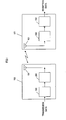
- FIG. 1 is a diagram showing a communication system using the conventional impulse modulation signal, wherein 150 represents a transmitter apparatus and 151 a receiver apparatus.
- the transmitter apparatus 150 comprises an antenna section 101 and a transmission modulator 102 while the receiver apparatus 151 comprises an antenna section 101 and a reception demodulator 103.
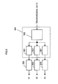
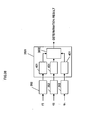
- Fig. 2 is a diagram explaining in detail the transmitter apparatus 150 and the receiver apparatus 151 shown in Fig. 1 , thus configuring a transceiver apparatus as a combination of the transmitter apparatus 150 and the receiver apparatus 151 for the sake of convenience.
- 250 is a filter section for inputting a signal and divides it into a plurality of subcarrier signals narrower in bandwidth than the input signal.
- 102 is a reception demodulator for inputting a plurality of subcarrier divisional signals divided by the filter section 250 to thereby receive and demodulate it, which is configured by a reception section 202 and a demodulator 203.
- 202 is a reception section for power-amplifying the input reception signal and outputting an amplified signal.
- 203 is a demodulator for inputting the amplified signal, to detect information from reception time, amplitude and phase, etc. , and output reception data.
- 103 is a transmission modulator for inputting, modulating and power-amplifying the transmission data and outputting a subcarrier transmission signal, which is configured by a modulator 204 and a transmission section 205.
- 204 is a modulator for impulse-modulating the input transmission data on a predetermined scheme and outputting a subcarrier modulation signal.
- 205 is a transmission section for inputting and power-amplifying a subcarrier modulation signal and outputting a subcarrier-transmission signal.
- the signal outputted from the transmission section 205 is band-limited in its subcarriers by the filter section 250 so that a multiplexed transmission signal is supplied to the antenna section 101.
- the filter section 250 is formed by a plurality of filters 201 for band limitation.
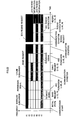
- the filter section 250 has apass characteristic assumably configured as shown in Fig. 3 . Namely, the plurality of filters 201 are to respectively limit different bands, and correspond to the subcarriers shown in Fig. 3 .
- the transmission apparatus 150 is made up by a transmission modulator 103, a filter section 250 and an antenna section 101.
- the reception apparatus 151 is constituted by an antenna section 101, a filter section 250 and a reception modulator 102.
- the modulator 204 inputs transmission data, and impulse-modulates it according to a predetermined procedure.
- Impulse modulation is known including pulse-position modulation that is to superimpose information over pulse time interval, pulse-phase modulation that is to superimpose information over pulse phase, and pulse-amplitude modulation that is to superimpose information over pulse amplitude.
- an impulse modulation wave is generated corresponding to transmission data, to output a subcarrier modulation signals in an amount of a predetermined number of subcarriers.
- the subscribers are attached with the same symbol.
- the subcarrier modulation signals are inputted to the transmission sections 205, to be output as power-amplified subcarrier transmission signals therefrom.
- the power-amplified subcarrier transmission signals are inputted to the filter section 250 and band-limited by the corresponding filters 201.
- the impulse modulation signal has a feature having a much-broadened band because it is an impulse-natured signal. Consequently, there is a feature that, even when passed through a narrower-banded filter having a different center frequency, there exists a corresponding frequency component. Thus, output is obtainable in accordance with a filter.
- the transmission signal outputted from the filter section 250 is such a signal as having a frequency characteristic shown in Fig. 3 , in a state multiplexed with a plurality of subcarrier signals 201 to 207.
- the transmission signal is supplied to the antenna section 101, to radiate an electromagnetic wave by the radiation characteristic thereof.
- the electromagnetic wave thus radiated is received by the antenna section 101 of the reception apparatus 151, to output a reception signal.
- the reception signal is divided into subcarriers band-limited by the filters 201 of the filter section 250, to be output as subcarrier divisional signals.
- the filter section 250 has the same frequency characteristic as that band-limited by the transmission apparatus 150.
- the reception signal in the entire power is turned into subcarrier divisional signals without substantial loss through the filters 210.
- the subcarrier divisional signals thus band-limited are power-amplified by the reception sections 202 from which subcarrier reception signals are outputted and those are supplied to the demodulator 203.
- the subcarrier reception signals inputted to the demodulator 203 are demodulated according to pulse interval, amplitude and phase, and turned into reception data.
- Fig. 12 is a figure showing a relationship between an impulse signal 1201 and a disturbing wave 1202, showing a state there exist one broadband signal 1201 (broken line), seven subcarrier signals 1203 and one disturbing wave 1202.
- Fig. 13A is a figure showing an impulse modulation signal superimposed thereon with a disturbing signal.
- Fig. 13B is a figure showing subcarriers f4, f5 of the impulse modulation signal at that time.
- Fig. 13C is a figure showing subcarriers f1 to f3, f6 and f7. Now consider here the case to communicate an impulse modulation signal remained as a broadband signal and the case to communicate it through division into subcarriers as noted before, in order for comparison.
- the disturbing wave in the case that similarly a disturbing wave is superimposed over the communication signal divided into subcarriers, there is encountered a deterioration in the communication condition in subcarriers f4, f5 under heavy influence of the disturbing wave shown in Fig. 12 , by the influence of the disturbing wave as shown in Fig. 13B .
- the disturbing wave is band-limited by the filter 201 as shown in Fig. 13C with a result that the major part of disturbing wave power is removed to obtain high C/N.
- the disturbing wave in few cases, has a power over a broad band, i.e. intense power frequently exists in a particular band.
- subcarrier arrangement is established by the filter section 250.
- this can be designed freely. Disturbing waves frequently occur due to the use for communications or so by the other systems, and wherein it is possible to know in advance a band being used in the system in this manner. For this reason, by the design to previously avoid such disturbing wave bands by means of the filter section 250, communication failure due to other systems can be reduced to the minimum.
- the subcarrier allocation must not be perfectly the same on the transmission apparatus 150 and reception apparatus 151. Instead, communication is possible where there is an overlap in a given band. Namely, there is no necessity to maintain high the frequency characteristic accuracy of the filter sections 250 set up on each of the transmission apparatus 150 and the reception apparatus 151. In this manner, where there is a deviation in the frequency characteristic to be established by the filters 201 provided on the filter section 250, compensation is possible for those variations as errors. This approach is explained by use of Figs. 4 , 5 and 11 .
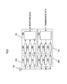
- Fig. 4 shows a further detail showing of the reception demodulator 102 in Fig. 2 .
- f1 - fn respectively represent subcarrier signals.
- 401 is a compensation section for compensating for an error (variation) occurring on each of the subcarrier-signal sequence and outputting a subcarrier compensated signal.
- 402 is an operation section for inputting subcarrier compensated signals and outputting an addition-operated carrier signal.
- 403 is a detection section for inputting a carrier signal and detecting an amplitude, phase and pulse interval of the pulse, to output corresponding reception data.
- a subcarrier divisional signal f2 is shown as a reference signal.
- the broken line depicted on each subcarrier divisional signal f1, f3 shows a reference signal f2, which is depicted in order for comparison.
- the subcarrier divisional signal f1 has an amplitude characteristic a1 (reference signal amplitude is normalized 1) and a delay characteristic td1 while subcarrier divisional signal f3 has an amplitude characteristic a3 and a delay characteristic td3, the compensation section401 corrects for the variation while controlling the delay time and amplitude.
- the compensation section401 corresponding to a subcarrier f1 sets a delay time at td + td1 and an amplitude gain at 1/al to thereby output a subcarrier compensation signal f1.
- the compensation section402 corresponding to a subcarrier f2 sets a delay time at td + 0 and an amplitude gain at 1
- the compensation section402 corresponding to a subcarrier f3 sets a delay time at td - td2 and an amplitude gain at -1/a3, thereby respectively outputting subcarrier compensation signals.
- a compensation section501 can be introduced in the modulator 204 similarly to the demodulator 203.
- the principle/operation is similar to the compensation section401 provided in the demodulator 203, and hence is omitted of explanation. In this manner, higher quality of communication can be secured by compensating for subcarrier-based variations by use of the compensation section501 in the modulator 204.
- the function of the compensation section401 can be incorporated in the matched filter characteristic. It is the correlator that is known the most as a matched filter structure. The correlator is quite easy to be realized by adjusting a signal pattern used in correlation on a subcarrier-by-subcarrier basis. Likewise, in the waveform generation section 502, the effect of the compensation section501 can be incorporated by adjusting the pattern of a generating impulse pattern on a subcarrier-by-subcarrier basis.
- the present invention is characterized in that an impulsive broadband signal is divided into subbcarriers to be received and demodulated. This is not limited to the configuration shown in Fig. 2 . As shown in Fig. 14 , it can be implemented on an arrangement in which the filter section 250 and the reception section 202 and transmission section 205 are exchanged. In addition, similar effect is available even if there is no filter section 250.
- the antenna section 101 in Figs. 1 and 2 can cover the entire of subcarrier band by means of a single antenna element, a plurality of antenna elements may be provided corresponding to predetermined subcarriers.
- a plurality of antenna elements may be provided corresponding to predetermined subcarriers.
- the present invention because using the scheme of communications through subcarrier division, does not require to overlap between antenna-based bands or match the antenna-based characteristics.
- the antenna element having a narrower band characteristic has many excellent points in terms of radiation characteristic (e.g. antenna gain), mechanical form, etc. From this fact, size reduction and performance improvement is readily achieved on the communication apparatus structuring an antenna section 101 with the use of a plurality of antenna elements.
- the present invention is characterized conspicuous in that the impulse modulation signal is divided into subcarriers for the processing of transmission and reception in the transmission apparatus 103 and reception apparatus 102 or only within the reception apparatus 102.
- the impulse modulation communication apparatus does not require various circuits for processing of high-frequency waves (linear amplifiers, synthesizers, filters). This can reduce by far the circuit scale as compared to the increased circuit scale by the increase of subcarrier-based sequence. For this reason, the present invention can be carried out extremely easily, having a feature that great effect is obtainable while suppressing circuit burden.
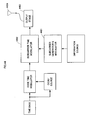
- Fig. 40 is a diagram showing an arrangement of a transmission apparatus 150 and reception apparatus 151 according to the present embodiment.
- the transmission modulator 103 has further a channel control section 4001 while the reception demodulator 102 has further the channel control section 4001.
- the channel control section 4001 selects and controls the subcarriers to be used on a channel-by-channel basis.
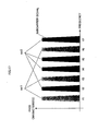
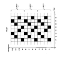
- Fig. 15 a correspondence between a communication and a subcarrier.
- channel 1 is under communication by use of subcarriers f1, f3, f4, f6 while channel 2 is under communication by use of subcarriers f2, f4, f5, f7.
- subcarrier setting is assumed similar in the transmission apparatus 150 and in the reception apparatus 151.
- the subcarrier configuration of channel 1 and the subcarrier configuration of channel 2 are in the form of sharing subcarrier f4.
- Fig. 16 a signal waveform on each subcarrier-based sequence.
- subcarriers f1, f3, f6 and subcarriers f2, f5, f7 are occupied on the single channel without duplication. Consequently, impulse detection is possible without any problem.
- a subcarrier f4 is in a state in duplicated use by channel 1 and channel 2. For this reason, when to detect an impulse, there is a possibility that it cannot be normally done due to interference.
- the reception apparatus 151 despite cannot normally detect an impulse on subcarrier f4 , can normally detect an impulse phase, amplitude, time, etc. on the other carrier (f1, f3, f6 on channel 1; f2, f5, f7 on channel 2). Therefore, it can be understood that communication is available only by those subcarriers. Moreover, in the case that there is a constant deviation in symbol time between channel 1 and channel 2, it is possible to separate the impulse of subcarrier f4. By doing so, the subcarriers duplicated between the channels can be separated and utilized in demodulation on each channel. As a result, the total power to be used per channel is improved and communication quality is expectedly improved.
- channel capacity can be secured to a maximum extent by assigning one subcarrier to one channel. Meanwhile, by assigning all the subcarriers to one channel, more stable communication can be provided because of securing a signal power per channel. In this manner, it is possible to freely establish the number of subcarriers assigned to one channel. This makes it possible to assign to the channel a smaller number of subcarriers where much more channel capacity is needed, and a greater number of subcarriers where more stable communication is required.
- the channel for conveying such important information as having a direct bearing upon system control and in such a channel as comparatively attaching importance to communication capacity such as of data for use in application more subcarriers can be assigned to the former channel as compared to the latter channel, allowing for architecting an efficient system.
- the number of subcarriers in assignment may be changed depending upon a communication capacity change, a propagation condition change or an interference wave condition change.
- stable communication quality can be sustained by previously monitoring the subcarrier condition so that the subcarriers in assignment to the channel are dynamically changed in the event that reception power is lowered, an interference wave signal is detected or interference becomes problematic at between the channels.
- the impulse modulation signal is divided into two or more subcarriers to thereby multiplex a plurality of channels
- a particular subcarrier is provided as a control channel exclusive for control information.
- important information is communicatable which is to be used in control or the like independently of the traffic channel.
- the impulse modulation scheme is divided into two or more bands (subcarriers) so that communication is effected by spreading codes to the subcarrier.
- Embodiment 1 was explained to implement communication to attach the same symbol on all the subcarriers assigned to one channel. However, in the case a plurality of subcarriers are assigned to one channel, there is no need to send the same symbols to all the subcarriers assigned.
- Fig. 17 shows a relationship between a subcarrier and a code. The example shown in Fig. 17 shows a state that subcarrier f1 - f7 are assigned to a certain channel. Meanwhile, this figure represents that symbol set ssl is used in transmission for subcarriers f1, f3, f6 while symbol set ss2 is used in transmission for subcarriers f2, f4, f5, f7.
- This system includes at least two symbols (s1, s2).
- symbols e.g. s1 ⁇ c1, s2 ⁇ c2
- c1, c2 transmitting codes
- the reception apparatus 151 obeys the same definition of symbol set, to determine the reception data by means of a combination of symbols received by each subcarrier.
- the conversion method of symbol set is explained more concretely. Considering symbol c1 as +1 and code c2 as -1 in the symbol set example referred before, it can be seen realizable if +1 is multiplied on the transmitting code in concerned with symbol set ss1 and -1 on the transmitting code in concerned with symbol set ss2. Particularly, the multiplication between sets +1 and -1 is known configured by exclusive OR. It is possible to extremely easily change different symbol sets on a subcarrier-by-subcarrier basis.
- Fig. 18 shows a state seven subcarriers (f1 - f7) are assigned for code division multiplexing.
- symbol sets ss1, ss2 uses the same modulation scheme wherein definition is made as (s1 ⁇ c1, s2 ⁇ c2) in ss1 while (s1 ⁇ c2, s2 ⁇ c1) in ss2.
- the transmission apparatus 150 makes a spreading in the carrier direction by use of diffusion codes sc1 - sc7 set on a chanel-by-chanel basis, to transmit signal through multiplex by a predetermined number of channels (seven, here).
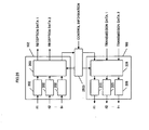
- Figs. 9 and 10 shows in greater detail the reception modulator 102 and transmission modulator 103 of Fig. 2 , wherein like reference is attached to like function.
- the reception demodulator 102 comprises a reception section 202, a spread code storing section901, a dispread section 902 and a detection section 403.
- 901 is a spread code storing section for storing and outputting a spread code set based on each channel
- 902 is a dispread section for outputting a dispread communication signal synthesized by inputting a reception signal in an amount of the number of subcarriers and multiplying thereon a spread code corresponding to the subcarrier into synthesis.
- the transmission modulator 103 comprises a transmission section 205, a spread code storing section901, a spread section1001 and a waveform generation section 206.
- 1001 is a spread section for inputting a spread code and a waveform generated communication signal and multiplying a communication signal divided into subcarriers by the corresponding spread code and outputting a spread communication signal.
- reception demodulator 102 and transmission modulator 103 configured as above is explained in detail.
- the waveform generating section 206 When transmission data is inputted to the transmission modulator 103, the waveform generating section 206 generates a symbol waveform corresponding to the data and outputs a communication signal.
- the communication signal is divided into communication signals corresponding to the subcarriers inputted to the spread section1001.
- the communication signal divided is multiplied by a corresponding code of the spread code outputted from the spread code storing section 901, to thereby be output as a spread communication signal.
- the spread communication signals are subjected to power-amplification and the like by the corresponding transmission section and radiated through the antenna 101.
- the reception demodulator 102 inputs the spread reception signal of from the antenna 101.
- the spread reception signal is inputted in an amount of the number of subcarriers, those of which are power-amplified by the reception section 202.
- the spread reception signal power-amplified is multiplied by and synthesized with a spread code corresponding to the subcarrier outputted by the spread code storing section901, to be output as a dispread reception signal.
- This dispread reception signal is inputted to the detection section 403, detected and output as reception data.
- the transmission modulator 103 makes a spreading on a subcarrier-by-subcarrier basis according to a spread code.
- the reception demodulator 102 makes a reception by similarly carrying out a dispread, thus having a conspicuous feature enabling code division multiplexing (CDM).
- CDM code division multiplexing
- the impulse modulation scheme is divided into two or more bands (subcarriers) so that communication is effected by sequentially changing the subcarrier for use in communication.
- reception demodulator 102 and the transmission modulator 103 those of Figs. 9 and 10 are used in explanation similarly to embodiment 3.
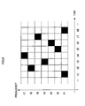
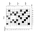
- Fig. 6 is a figure explaining a hopping pattern that the subcarrier for use in communication is changed in order.
- a subcarrier change in a unit time by taking a time on abscissa and a frequency (subcarrier) on ordinate, showing that the hatched block is a subcarrier used in communication
- this hopping pattern is shared by the transmission end and reception end.
- the shared hopping pattern is stored in the spread code storing section901 shown in Figs. 9 and 10 , wherein storage is with spread codes of +1, 0 instead of +1, -1.
- the transmission modulator 103 transmits a communication signal while changing the subcarrier in time.
- the reception demodulator 102 is to change the hopping pattern in time, thereby selecting and receiving a subcarrier which the transmission modulator 103 is using in communication. This enables to correctly receive data.
- Fig. 8 is a figure showing a hopping pattern when a plurality of carriers are used simultaneously. Design is made to use four subcarriers in one unit time, providing four times the reception power at the reception demodulator 102.
- the hopping pattern stored in the spread code storing section901 has numbers +1 and 0 only (one +1 and six 0s in the former example, and four +ls and three 0s in the latter example).
- subcarriers By adjusting the number of subcarriers for use in communication as in the above manner, stable communication is made feasible. Meanwhile, by changing the number of subcarriers in time, subcarriers can be given smaller in the number in well communication condition while subcarriers be given greater in the number in worse cases.
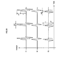
- Fig. 7 shows a state that two channels are multiplexed by frequency hopping.
- Channel 1 and channel 2 shown in the figure make communications with using respective ones of subcarriers in unit time.
- the number of subcarriers per unit time can be changed on a channel or time basis.
- a plurality of channels can be multiplexed to enable communication.
- Fig. 19 shows a figure showing a system configuration comprising a communication apparatus having a bi-directional communication function.
- the figure takes a symmetric system as an example, it is satisfactory to use such an asymmetric system as 1-to-N.
- communication from a communication apparatus 1950 to a communication apparatus 1951 is explained as downlink while communication from a communication apparatus 1951 to a communication apparatus 1950 is as uplink, those communication directions are not to limit the substance of the present technique.
- Fig. 20 shows a subcarrier on-frequency allocation. This shows a manner of coexistence of uplink subcarriers and downlink subcarriers, showing a manner that frequency division duplex can be carried out without problem because channel orthogonality is held by the subcarriers.
- time division In this case, control is required not to cause time overlap. With frequency division, time division control becomes unnecessary. Hence, realization is possible with simple configuration.
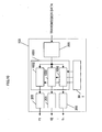
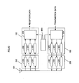
- Fig. 25 is a showing of the communication terminals 1950, 1951 in greater detail.
- the communication terminal 1950, 1951 comprises a reception demodulator 102, a transmission modulator 103 and a carrier control section 2503.
- the reception demodulator 102 comprises a reception section 202, a switch section 2501 and a detection section 203, to input two or more subcarrier signals f1 to fn, input a carrier control signal 2510 and detect and output a signal of the corresponding carrier.
- the transmission modulator 103 comprises a waveform generating section 206, a switch section 2501 and a transmission section 205, to input transmission data 2513 and a carrier control signal 2511 and generates an impulse string corresponding thereto, thus outputting an impulse signal to the corresponding carrier.
- the carrier control section 2503 inputs control information 2514 and control data 2515 of from the reception demodulator 102, and outputs carrier control signals 2510, 2511 depending upon a carrier assignment sequence.
- Fig. 22 shows a frequency assignment sequence, showing the steps of management such as assignment/reallocation of a plurality of subcarriers. Meanwhile, Fig. 24 shows a sequence for initial setting. Fig. 41 is a flowchart showing a communication operation of the present embodiment.
- the carrier control section 2503 sets a subcarrier for use in communication to an initial value, according to control information 2514. It is possible to consider, as the initial value, setting for assignable subcarrier all usable, setting usable assignable subcarrirers excepting a predetermined particular subcarrier, and the like.
- the signal corresponding to a subcarrier selected in this manner is outputted to the switch section 2501 of the reception demodulator 102 and transmission modulator 103, thus determining switch status (step S4101).
- the signal received by the reception section 202 is inputted to the detection section 203 through the switch section 2501.
- the detection section 203 detects subcarrier-based reception power and outputs a result thereof as control data 2515 to the carrier control section 2503.
- the carrier control section 2503 records as communication-not-permitted carrier a carrier having reception power exceeding a predetermined value (step S4102).
- a predetermined initial signal is inputted as transmission data 2513, to generate a corresponding impulse signal through the waveform generating section 206.
- This impulse signal is selected of subcarriers by the switch section 2501 and outputted through the transmission section 205 (step 4103).
- the initial signal is received by the reception modulator 102 and inputted to the detection section 203 through the switch section 2501.
- the detection section 203 the initial signal as a known signal is used to carry out time synchronization, subcarrier-based characteristic compensation setting and subcarrier quality detection. In the case the quality does no reach a predetermined value, the corresponding carrier is recorded as incompetence for data communication (step 4104).
- the above operation enables to know a use state of a frequency resource for use in communication. Namely, interfering immunity of from external system can be detected by session 1 and mutual-communication propagation characteristic can be by session 2a/2b.
- the subcarrier usable in communication can be shared by the both terminals.
- the carrier control section 2503 of the communication terminal 1950, 1951 determines an uplink/downlink subcarrier according to a predetermined rule.
- the reception modulator 102 of the communication terminal 1950 is set up with an uplink subcarrier while the transmission modulator 103 is set up with a downlink subcarrier.
- the reception demodulator 102 is set up with a downlink subcarrier while the transmission modulator 103 is set up with an uplink subcarrier.
- similar operation is enabled by temporarily setting uplink and downlink by a predetermined method (ID code magnitude).
- the communication terminal 1950 transmits a determined downlink subcarrier.
- the communication terminal 1951 receives the downlink subcarrier received, the information is inputted as control data 2515 from the detection section 203 to the carrier control section 2503.
- control data 2515 set is the status of switch 2501 in the reception demodulator 102 (step S4105).
- the communication terminal 1951 transmits determined uplink subcarrier information similarly to session 3a.
- the communication terminal 1950 receives the uplink subcarrier information
- the information is inputted as control data 2515 from the detection section 203 to the carrier control section 2503.
- set is the status of switch section 2501 in the reception modulator 102 (step S4105).
- the both communication terminals sets the switch section 2501 in the transmission modulator 103, to downlink subcarrier in the communication terminal 1950 and to uplink subcarrier in the communication terminal 1951, thus completing the setting of uplink/downlink subcarriers (step S4106).
- the communication terminals 1950, 1951 start a communication by use of the uplink subcarrier and downlink subcarrier (step S4107).
- the above procedure enables subcarrier assignment. Because such a procedure if conducted enables to previously examine the interference characteristic with other systems prior to communication start, it is easy to grasp a subcarrier usable in communication. Simultaneously therewith, because subcarrier communication condition is examined between the communication terminals, it is easy to grasp a propagation status formed between the communication terminals. Finally, it is possible to easily select a subcarrier suited for communication.
- the subcarrier assigned in the above initial state when requiring a downlink (or uplink) band, can add and utilize free subcarriers f3, f6, as shown in communication state (1). By doing so, system flexibility can be secured by changing subcarrier utilization ratio in accordance with communication band. Further, because of no use of unnecessary band, power-saved communication is feasible that is high in frequency utilization ratio.
- communication state (2) where uplink (or downlink) requires the maximum band, a communication system high in frequency utilization efficiency and maximum transmission capability can be architected by implementing communications by utilization of all the subcarriers determined usable in the subcarrier status examination conducted in the initial operation.
- communication state (3) when to desirably send at the maximum transmission capability, it is effective to leave at lest one subcarrier free as out of use in the uplink or downlink. This makes it possible to use the out-of-use subcarrier in exchanging control signals, exchanging resend information or the like, thus enabling higher-leveled control/quality management.
- communication state (4) there is a feature that control is made simple by allocating the subcarriers for assignment in the uplink/downlink according to a given rule. At this time, the rule can be considered to randomly assign the subcarrier numbers, to be assigned in the higher (or lower) order on the frequency axis, on the frequency axis thereby making an assignment in the order of the subcarrier number.
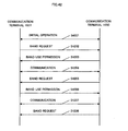
- Fig. 42 is a sequence chart showing a communication operation according to the present embodiment.
- step S4201 a state that subcarriers are assigned to uplink/down link by the initial operation (step S4201) shown at step S4101 to S4106.
- the communication terminal 1951 when requiring a transmission capacity, sends an uplink signal including a band request signal (step S4202).
- the communication terminal 1950 when receiving the band request signal, examines that a subcarrier requested is not in use. Then, it sends a downlink signal including a band-use permission signal and sets the corresponding subcarrier to a reception state (step S4203).
- the communication terminal 1951 when receiving the band-use permission signal, sets the permitted subcarrier to a transmission state and starts a communication (step S4204).
- the transmission terminal 1950 when requiring a transmission capacity, sends a downlink signal including a band request signal (step S4205).
- the communication terminal 1951 receives the band request signal and conducts an interference examination on the subcarrier requested. Confirming an interference of subcarriers as a result of examination, the communication terminal 1951 determines whether or not to release it. In the case to release, the interfering subcarrier is released and simultaneously a band-use permission signal included in an uplink signal is sent. Conversely, in the case not to release it, a band-use permission signal is generated in a manner to permit a part of band only, or in a manner to reject whole band required, to send an uplink signal including it (step S4206).
- the communication terminal 1950 when receiving the band permission signal, makes a switching over to the corresponding subcarrier and starts a communication (stepS4207).
- a band request signal is again sent after a lapse of a predetermined time (step S4208).
- the band request signal and the band-use permission signal can be exchanged solely to increase/decrease the number of subcarriers.
- the band request signal can be added therein with use information. Namely, by including in a band request signal a use as numerical information about a degree of significance, urgent degree or scheduled use time or the like, a higher level of assignment operation is feasible.
- band assignment procedure was explained in the above, there is a resend method as one technique for improving communication quality. Although this procedure can be grasped similarly, it may be a separate process if considering it as temporary use. A procedure rendered as a separate one is shown in the below.
- the communication apparatus 1950 when confirming a trouble occurrence in transmission over the uplink, sends a downlink signal including a resend request signal 2210.
- the communication terminal 1951 when detecting a resend request signal 2210 out of the reception signal, looks for a free band and outputs a resend notification signal representative of resending by use of an out-of-use subcarrier.
- the communication terminal 1950 when receiving the resend notification signal 2211, sets the corresponding subcarrier into that for reception and starts to receive resend information.
- the communication terminal 1951 after a lapse of a predetermined time, puts the resend information 2212 onto the subcarrier designated before and carry out communication. After sending the resend information, it releases the subcarrier used for the same and returns to the former communication state.
- the communication terminal 1951 determines to select as a subcarrier any one of a subcarrier being used in the uplink or a subcarrier being used in the downlink, and sends the information thereof together with a resend notification signal 2211.
- the communication terminal 1950 when receiving the resend notification signal 2211, detects whether or not there is a necessity to release the subcarrier for downlink. In the case there is a necessity of release, the subcarrier is released and the same is set for reception.
- the communication terminal 1951 after a lapse of a predetermined time from sending of the resend notification signal 221, sends resend information by use of a corresponding subcarrier.
- the communication terminals 1950, 1951 notify to each other a communication start status by use of a control signal, as a preparation prior to the initial state (1).
- the communication terminal 1950 transmits a control signal representative of a communication start by the use of predetermined one or more subcarriers.
- the communication terminal 1951 receiving it makes a preparation for the initial state (1).
- the communication terminals 1950, 1951 notify a fact of subcarrier assignment completion, by the use of the control signal.
- the communication terminal 1950 notifies completion of the assignment of a subcarrier for use in communication, thus making a control such that the subsequent communication is carried out by use of the assigned subcarrier.
- the communication terminals 1950, 1951 notify a negotiation completion to each other. This is assigned with at least three subcarriers for uplink, downlink, and control, to carry out a communication between the communication terminals 1950, 1951.
- the above procedure enables subcarrier assignment.
- control information can be exchanged without having an effect upon information conveyance of from another system in the course of communication or upon transmission capacity at between the communication terminals 1950. 1951.
- This enables to architect a stable communication system.
- subcarrier request/assignment can be effected in a unitary fashion, hence enabling to easily architect an efficient high-performance communication system.
- subcarrier f4 can be assigned as a subcarrier for control.
- the operation in this case is explained by using Fig. 23 .
- Fig. 23 this is the case similar to the foregoing embodiment except in that a request signal and permission signal are exchanged only by subcarrier f4. Due to this, control information can be exchanged at all times, hence eliminating the prohibition against request issuance until becoming free of a subcarrier.
- the present embodiment explained the operation on the apparatus shown in Fig. 25 .
- the switch section 2501 is rendered unnecessary thus enabling practical application with a simple structure as shown in Fig. 26 .
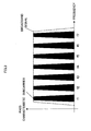
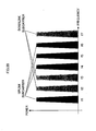
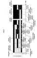
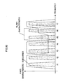
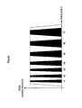
- Fig. 43 is a figure showing a subcarrier band characteristic in the present embodiment. This band characteristic is realized by the modulator 204 of the transmission apparatus and demodulator of the reception apparatus in the present embodiment. Excepting this point, this has the same configuration as embodiment 1.
- the subcarrier having a higher center frequency is assigned with a broader band.
- the subcarrier having a high frequency is limited in communication area and hence can be repeatedly utilized as compared to the lower subcarrier.
- the shields because of high attenuation by the shields, it is characterized in that there is less leakage to the adjacent room (partition, building).
- it can be considered efficient to assign a broadband. Namely, by assigning a broader band to a subcarrier having a high center frequency to thereby practicing higher-speed of communication, it is possible to easily architect a system high in (frequency, space) utilization efficiency.
- system stability can be improved rather by keeping propagation condition well and selecting a subcarrier having a broader communication area. Namely, by assigning control information to a subcarrier lower in center frequency, a stable communication system can be provided. Meanwhile, in the lower frequency band, there is a high possibility that it is a frequency band to be used by other systems. (This is because it is a general practice to determine the frequency bands for use by a system in the order of from lower frequency.) In consideration of this, it is preferred to establish subcarriers in accordance with system's use (i.e. taking account of free channels) instead of setting control information to a subcarrier the lowest in center frequency.
- a low-frequency subcarrier is assigned for communication requiring circuit quality, e.g. important information, control information and information transmission requiring communication quality.
- higher-frequency subcarriers are assigned. This can easily provides the optimal allocation.
- by assigning a broader band to a subcarrier having a higher center frequency higher-speed of broadband communication can be realized with the subcarrier.
- control information can be communicated by frequency hopping. This is because, where there are subcarriers stable in communication environment, there are increasing cases to enhance quality rather in transmission by a particular subcarrier. Furthermore, it is possible to use, in information, direct sequence technique in preparatory for an unforeseen event (e.g. sudden interfering signal issuance by another system (or apparatus)). Furthermore, the control signal frequently has information to be shared by some apparatuses. By multiplexing those by code division multiplexing or time division multiplexing, some control signals can be stably exchanged by the same subcarrier. In the other subcarriers than that used for the control signals, it can be considered to use frequency hopping or assign a given subcarrier in compliance with information kind.
- Embodiment 4 explained the technique for carry out frequency hopping based on each subcarrier.
- the frequency hopping technique can reduce the symbol rate on one subcarrier, making it possible to relieve the effect of multipath.
- the space where electromagnetic waves propagate is generally constituted with some different propagation paths based on reflection, diffraction, transmission and the like.
- the difference in path length due to the difference of propagation path appears in the form of a difference in delay amount. It is expressed in delay dispersion by use of the delay time and attenuation amount. Because a reception signal is given as a synthetic result of delay dispersion and transmission waveform, different reception waveforms are observed by a propagation space formed between transmission/reception terminals.
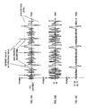
- Figs. 33 to 36 show signal waveform figures.
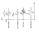
- Fig. 33 shows a relationship of a delay wave caused by the characteristic (delay dispersion) of a space where a transmission waveform (impulse signal) propagates and a reception wave as a synthesis thereof.
- delay dispersion the characteristic of a space where a transmission waveform (impulse signal) propagates
- reception wave a reception wave as a synthesis thereof.
- an impulse signal having two peaks if added with a delay dispersion characteristic, changes into a signal having a number of local peaks.
- Figs. 34A and 34B show relationships where an impulse string is inputted to the signal waveform of Fig. 33 .
- the signal waveform of Fig. 34A and the signal waveform of Fig. 34B respectively depict reception waves where impulse interval (symbol rate) is given tsymbol_A and tsymbol_B (where tsymbol_A ⁇ tsymbol B), respectively depicting, with superimposition, to see a relationship of a single-impulsed reception wave.
- impulse interval is smaller than the maximum delay amount (tdelay) of delay dispersion
- the reception waveform has an interference at between single-impulse signals, to turn into a complicated waveform difficult to demodulate.
- the reception waveform is a combination of single-impulsed signals. This can be understood demodulatable.
- a stable communication system can be architected by changing the symbol rate by depending upon a delay dispersion formed in a propagation space by the transmission terminal.
- the method for the transmission terminal to determine a delay dispersion can be a method of calculation/estimation by use of a reception signal of from the opposite of communication, a method of conveying a status of a delay dispersion calculated by the opposite of communication onto the transmission terminal, and so on.
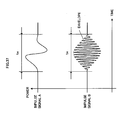
- Fig. 35 shows a relationship between a delay dispersion and a delay wave and reception wave where the impulse width (tw) of a transmission waveform (impulse signal) is increased.
- the impulse width (tw) of a transmission waveform impulse signal
- the signal in the case with a short impulse width is shown by a dotted line.
- tdd delay difference
- tdelay maximum delay amount
- Fig. 36 is a depiction of a signal waveform relative to an impulse string similarly to Fig. 34A or Fig. 34B .
- the waveform of the reception wave is approximated to an impulse form by setting the impulse width (tw) long and further taking the impulse interval (tsymbol) long, demodulation operation can be simplified, i.e. stable communication is made possible.
- the impulse signal (A) in Fig. 37 shows a single-pulse signal waveform while the impulse signal (B) shows a pulse-shaped signal waveform.
- controlling the impulse wave results in a change of signal band.
- signal band is narrowed by increasing the impulse width while signal band is broadened by decreasing it.
- a constant (e.g. 500 MHz) or higher band is required to utilize in communication known as the UWB (ultra wideband) system.
- limitation can be provided in the control range of impulse width.
- Explanation is made on a technique of implementing communication with two or more subsets by using a certain number of subcarriers as a subset, in a system for communicating an impulse modulation signal by using subcarriers.
- FIGs. 27and28 there is shown an on-frequency allocation of subcarriers f1 - f12.
- f1 - f4/f5 - f8/f9 - f12 are considered respective one sets, which are assumed as subsets 1 - 3.
- the communication system using subcarriers so far shown in the other embodiment can be grasped as a system having those allocated in the number of subsets.
- the number of subcarriers included in the subset can be reduced to a proper number, it is possible to easily carry out subcarrier management/control.
- Fig. 32 shows a case that the filter characteristic is not separated on a subset-by-subset basis.
- the subset singly cannot be operated independently. Namely, signal separation is not made between one subcarrier and another subcarrier as in subcarriers f3 to f6, the subcarriers are influenced in their mutual communication states. For this reason, by providing a filter characteristic corresponded at least to the subsets, signal separation is achieved at between the subsets thus enabling to independently operate the subsets.
- Fig. 31 takes an arrangement that frequency conversion is made on the reception signal of subcarriers f1 - fn frequency-allocated with the subset by the same variable clock in a frequency conversion section 3101, whose signals are added (or switched over) into a signal to be detected by one detection section 203. If explaining it by using fig. 27 , in the case of agreement between the f1 filter characteristic in Fig. 31 and the subset, because the subsets are already signal-divided in frequency, there is no mutual interference between subset f1 and subset f2 - fn. Accordingly, the detection section can be configured in the small number (one in Fig. 31 ). Namely, in Fig.
- the above reception apparatus can be configured.
- the filter characteristic corresponding to the subset is extremely broad in band and sufficiently high in response speed and the number of subsets are small as compared to the number of the subcarriers, it is possible to reduce the lower in simplicity due to the provision of filter characteristic and lower in response speed due to the filter, as mentioned above.
- the filter characteristic provided in the reception apparatus may be any of from an antenna frequency characteristic to a frequency characteristic as a filter element, and an amplifier frequency characteristic.
- the use of filter characteristic also as an antenna frequency characteristic greatly contributes to antenna size reduction and characteristic improvement.
- the antenna can be further reduced in size.
- subcarriers f1 - f7 shown in Figs. 3 , 6 , 7 , 8 , 12 , 15 , 17 , 18 and 20 - 24 may be replaced with subsets.
- subcarriers f1 - f7 shown in Figs. 3 , 6 , 7 , 8 , 12 , 15 , 17 , 18 and 20 - 24 may be replaced with subsets.
- a plurality of subcarriers are assigned to one subset, it is possible to carry out such an operation as direct sequence by use of a particular subcarrier or frequency hopping by use of a subcarrier assigned within the relevant subset.
- Figs. 29 and 30 shows a frequency hopping pattern where subsets are constituted as shown in Fig. 27 .
- Fig. 29 is the case where the communication apparatus performs transmission through one channel by using all the subsets while
- Fig. 30 is the case where three channels perform transmissions each using one subset.
- a high-function communication system can be architected by a simple configuration.
- the present embodiment explains an invention for detecting an output of a broadband signal by a simple configuration.
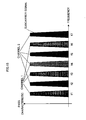
- Fig. 3 shows an on-frequency allocation of a broadband signal to be detected and detecting subcarrier signals.
- the broadband signal is shown by a dotted line and the subcarrier signals by hatching of f1 - f7.
- the broadband signal and the subcarrier signals have a frequency relationship set such that the entire or a part band of the subcarriers is positioned within a band of the broadband signal, as shown in Fig. 3 .
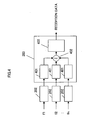
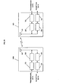
- Fig. 38 shows one example of an arrangement of a reception apparatus to be used in the invention. Note that the constituent element having like function in the figure is attached with like reference.
- the reception apparatus comprises a reception section 202 for decomposing a broadband signal into a plurality of subcarrier signals f1 - fn (narrow in band as compared to that) and receiving the decomposed signal group, and a determining section 3801 for inputting the received reception signal group and outputting a determination result.
- the determination section 3801 comprises a compensation section401 for inputting the received reception signal group and compensating for any of amplitude, phase, delay time and waveform of each signal, and a detection section 3802 for inputting a compensated signal and outputting a desired signal.
- the broadband signal is divided into signals (subcarrier signals) divided in predetermined bands by a filter (not shown), and inputted to the reception apparatus.
- the inputted subcarrier signals are compensated for in a manner easy to detect a phase, an amplitude, a delay time, a waveform, etc.
- the subcarrier signals separated from the same broadband signal are sought as signals high in time correlation depending upon the corresponding frequency characteristics.
- a filter characteristic or propagation path characteristic used in separation variation occurs in amplitude, phase, delay time, waveform, etc.
- an actual signal and an ideal waveform respectively by a solid line and a dotted line.
- subcarrier f1 is long in delay time and great in amplitude.
- subcarrier f3 is short in delay time and small in amplitude, wherein amplitude is inverted. In this manner, because the subcarrier signals varies depending upon a propagation characteristic and filter characteristic, a difference occurs in detection characteristic depending upon a communication condition and a combination of filters.
- the compensation section401 makes a compensation into a signal matched in amplitude, phase, delay time and waveform. Namely, compensation is performed in a manner approximate to the dotted line shown in Fig. 39 .
- delay time is desirably matched to the longest one if considering a fact that the delay element is easier to control.
- the subcarrier signals are outputted as signals matched in amplitude, phase, delay time and waveform, as shown in the dotted line in Fig. 39 .
- the signal detection section it is determined whether a communication signal has been received or not, by a detection time of an impulse equal to or greater than a constant level of among the subcarrier signal group and the number thereof. Namely, in the case of a simultaneous (within a set time difference) impulse detection out of a predetermined number of subcarrier signals, determination is made as receiving a broadband signal.
- the prior art requires operations including synchronization and demodulation in order to carry out only signal power detection.
- signal detection is made by using correlation operation at a constant time interval.
- correlation operation is complicated in operation, thus having a great problem in respect of circuit scale and power consumption leading to signal processing complication and consumption power increase.
- reception wait time occupies a great ratio as compared to the time executing communication.
- the present invention aims at resolving such a problem. Namely, when detecting a broadband signal as compared to the band which the general communication system utilizes, the influence of an interference signal is restricted by dividing it in frequency. By such division into some narrow-band subcarriers and detecting a communication signal on the basis of a signal power obtained from the subcarriers, it is possible to configure a communication signal detection apparatus extremely simple and low in consumption power.
- the detection signal thus determined is representative of a time of communication signal, and hence can be used as the initial synchronous signal with the subsequent signal. By doing so, a communication apparatus can be architected that is simple and low in consumption power.
- an operation result of addition of signal groups can be taken as a reference signal. Namely, determined is a signal that all the subcarrier signals are added and synthesized together. In the case the power value of the same exceeds a constant level, detection determination is carried out. Otherwise, with reference to a time the power value exceeds a constant level, in the case of detecting an impulse by a constant number of subcarriers within a constant time at around the same, detection determination is done. By doing so, operation is made possible at extremely low consumption power because the operation prior to signal detection is limited to reception, operation and power detection.
- the present invention is useful in electronic commerce transaction with utilization of a program broadcast with advertisement distribution, and suited for prompting the viewer to look an advertisement, carrying out sales promotion without discount of the advertisement product and extending the demand for pay broadcast.
Landscapes
- Engineering & Computer Science (AREA)
- Computer Networks & Wireless Communication (AREA)
- Signal Processing (AREA)
- Mobile Radio Communication Systems (AREA)
- Transmitters (AREA)
- Digital Transmission Methods That Use Modulated Carrier Waves (AREA)
Claims (12)
- Kommunikationsvorrichtung, aufweisend:einen Transmissionsmodulator (204) für Impulsmodulieren von Übertragungsdaten und Erzeugen von Unterträgern;ein Träger-Steuerbereich zum Steuern der Unterträger für Anwendung in Kommunikation abhängig von der Informationsmengen-, Signifikanz- und Kommunikationsverbreitungsbedingung; undeinen Antennenbereich (101) zum Abstrahlen der Unterträgersignale,dadurch gekennzeichnet, dassder Transmissionsmodulator ein schmaleres Band dem eine niedrigere Mittenfrequenz aufweisenden Unterträger und ein breiteres Band dem eine höhere Mittenfrequenz aufweisenden Unterträger zuordnet.
- Kommunikationsvorrichtung nach Anspruch 1, ferner aufweisend einen Empfangsmodulator (151) zum Erkennen von Empfangsdaten und Überprüfen einer Empfangsleistung auf jedem Unterträger,
zum Benachrichtigen des Unterträger-Steuerbereichs über eine Genehmigung/Nichtgenehmigung zum Anwenden des Unterträgers in Abhängigkeit von der durch Empfangsmodulator überprüften Empfangsleistung. - Kommunikationsvorrichtung nach Anspruch 2, wobei der Träger-Steuerbereich einen Sprung von zwei oder mehreren der Unterträger bewirkt.
- Kommunikationsvorrichtung nach Anspruch 2, wobei der Träger-Steuerbereich eine Spreizung von zwei oder mehreren der Unterträger bewirkt.
- Kommunikationsvorrichtung nach Anspruch 2, wobei der Transmissionsmodulator (204) eine frequenzabhängige Zuteilung der Unterträger in Übereinstimmung mit dem Kommunikationszustand ändert.
- Kommunikationsvorrichtung nach Anspruch 2, wobei der Transmissionsmodulator (204) ein Frequency Division Duplex (FDD) durch Anwenden von zwei oder mehreren Unterträgern ausführt.
- Kommunikationsvorrichtung nach Anspruch 2, wobei der Antennenbereich (101) eine Frequenzcharakteristik einer Multibandcharakteristik aufweist.
- Kommunikationsvorrichtung nach Anspruch 2, wobei der Antennenbereich (101) Funkwellen auf einer Unterträger-zu-Unterträger-Basis empfängt und das Unterträger-Signal an den Empfangsmodulator (151) ausgibt.
- Kommunikationsvorrichtung nach Anspruch 2, wobei der Empfangsdemodulator (151) Folgendes aufweist:einen Spreizcode-Speicherbereich zum Speichern eines Spreizcodes und Extrahieren eines Spreizcodes in Übereinstimmung mit dem Unterträger, undeinen Entspreizbereich zur Herstellung einer Faltungsoperation des Unterträgersignals und zum Extrahieren im Spreizcode-Speicherbereich.
- Kommunikationsvorrichtung nach Anspruch 2, wobei der Transmissionsmodulator (204) Folgendes aufweist
einen Spreizcode-Speicherbereich zum Speichern eines Spreizcodes und Extrahieren eines Spreizcodes in Übereinstimmung mit dem Unterträger, und
einen Spreizbereich zur Herstellung einer direkten Spreizung auf dem Unterträger von dem in die Unterträger geteilten Modulationssignal und Extrahieren am Spreizcode-Speicherbereich. - Kommunikationsvorrichtung nach Anspruch 2, wobei der Empfangsdemodulator (151) Folgendes aufweist
einen Umschaltbereich zum Umschalten durch Frequenzsprung auf dem Unterträger,
der Trägerbereich ausführend die Steuerung im Umschaltbereich. - Kommunikationsvorrichtung nach Anspruch 2, wobei der Transmissionsdemodulator (204) Folgendes aufweist
einen Umschaltbereich zum Umschalten durch Frequenzsprung auf dem Unterträger,
der Trägerbereich ausführend die Steuerung im Umschaltbereich.
Applications Claiming Priority (7)
| Application Number | Priority Date | Filing Date | Title |
|---|---|---|---|
| JP2002248266 | 2002-08-28 | ||
| JP2002248266 | 2002-08-28 | ||
| JP2002302947 | 2002-10-17 | ||
| JP2002302947 | 2002-10-17 | ||
| JP2003298489A JP4318510B2 (ja) | 2002-08-28 | 2003-08-22 | 通信装置および通信方法 |
| JP2003298489 | 2003-08-22 | ||
| PCT/JP2003/010920 WO2004021617A1 (ja) | 2002-08-28 | 2003-08-28 | 通信装置および通信方法 |
Publications (3)
| Publication Number | Publication Date |
|---|---|
| EP1533929A1 EP1533929A1 (de) | 2005-05-25 |
| EP1533929A4 EP1533929A4 (de) | 2012-04-11 |
| EP1533929B1 true EP1533929B1 (de) | 2015-08-12 |
Family
ID=31982124
Family Applications (1)
| Application Number | Title | Priority Date | Filing Date |
|---|---|---|---|
| EP03791368.8A Expired - Lifetime EP1533929B1 (de) | 2002-08-28 | 2003-08-28 | Kommunikationsvorrichtung und kommunikationsverfahren |
Country Status (6)
| Country | Link |
|---|---|
| US (1) | US7697624B2 (de) |
| EP (1) | EP1533929B1 (de) |
| JP (1) | JP4318510B2 (de) |
| CN (1) | CN1650556B (de) |
| AU (1) | AU2003257575A1 (de) |
| WO (1) | WO2004021617A1 (de) |
Families Citing this family (30)
| Publication number | Priority date | Publication date | Assignee | Title |
|---|---|---|---|---|
| US7570712B2 (en) * | 2003-02-28 | 2009-08-04 | Freescale Semiconductor, Inc. | System and method for transmitting ultrawide bandwidth signals |
| KR100664916B1 (ko) | 2003-05-07 | 2007-01-04 | 삼성전자주식회사 | 간섭의 동적 저감을 위한 uwb 송수신기 및 송수신 방법 |
| US20050113045A1 (en) * | 2003-11-21 | 2005-05-26 | John Santhoff | Bridged ultra-wideband communication method and apparatus |
| JP4043442B2 (ja) * | 2004-01-09 | 2008-02-06 | 株式会社東芝 | 無線送信装置、無線受信装置、無線送信方法及び無線受信方法、無線通信システム |
| KR100654434B1 (ko) * | 2004-06-09 | 2006-12-06 | 삼성전자주식회사 | Uwb 통신 방법 및 uwb 송신장치와 수신장치 |
| US8406331B2 (en) * | 2004-06-24 | 2013-03-26 | Koninklijke Philips Electronics N.V. | Method for signaling the status of a subcarrier in a MC network and a method for adaptively allocating the subcarriers in a MC network |
| JP2008505557A (ja) * | 2004-07-01 | 2008-02-21 | スタッカート・コミュニケーションズ・インコーポレーテッド | マルチバンド受信機同期 |
| US8023523B2 (en) | 2005-02-25 | 2011-09-20 | Kyocera Corporation | Communications systems |
| EP1859558A4 (de) | 2005-02-25 | 2011-03-09 | Kyocera Corp | Kommunikationssysteme |
| KR20060097450A (ko) * | 2005-03-09 | 2006-09-14 | 삼성전자주식회사 | 다중 셀 통신 시스템에서 자원 할당 제어 시스템 및 방법 |
| JP2006270236A (ja) * | 2005-03-22 | 2006-10-05 | Fujitsu Component Ltd | 通信システム、及び、送信装置、受信装置、並びに、通信装置 |
| US8693383B2 (en) | 2005-03-29 | 2014-04-08 | Qualcomm Incorporated | Method and apparatus for high rate data transmission in wireless communication |
| JP4862436B2 (ja) * | 2005-03-31 | 2012-01-25 | パナソニック株式会社 | インパルス波形生成装置および高周波パルス波形生成装置 |
| JP4515312B2 (ja) * | 2005-03-31 | 2010-07-28 | 株式会社エヌ・ティ・ティ・ドコモ | 移動局、送信方法および移動無線通信システム |
| JP2007228468A (ja) * | 2006-02-27 | 2007-09-06 | Oki Electric Ind Co Ltd | マルチキャリア周波数ホッピングシステム、送信回路及び受信回路 |
| JP4578446B2 (ja) * | 2006-07-24 | 2010-11-10 | パナソニック株式会社 | パルス送信装置、パルス受信装置、およびパルス通信システム |
| CN100576836C (zh) | 2006-09-15 | 2009-12-30 | 上海贝尔阿尔卡特股份有限公司 | 多入多出无线网络中对信号进行子载波映射的方法及装置 |
| TWI510032B (zh) * | 2007-08-06 | 2015-11-21 | Interdigital Patent Holdings | Egprs-2脈衝整形方法及wtru |
| JP2009303066A (ja) * | 2008-06-16 | 2009-12-24 | Nippon Telegr & Teleph Corp <Ntt> | 無線通信システムおよび無線通信方法 |
| US20100007355A1 (en) * | 2008-07-10 | 2010-01-14 | Litepoint Corporation | Method for testing radio frequency (rf) receiver to provide power correction data |
| JP4894826B2 (ja) * | 2008-07-14 | 2012-03-14 | ソニー株式会社 | 通信装置、通信システム、報知方法、及びプログラム |
| JP5380995B2 (ja) * | 2008-10-10 | 2014-01-08 | 株式会社リコー | 無線受信装置及び方法 |
| CN102217401A (zh) * | 2008-11-21 | 2011-10-12 | 富士通株式会社 | 基站、通信方法、副载波分配方法以及副载波分配程序 |
| EP2487980A4 (de) * | 2009-10-06 | 2016-08-10 | Ntt Docomo Inc | Basisstation, vorrichtung und mobiles kommunikationsverfahren |
| JP5037650B2 (ja) * | 2010-04-28 | 2012-10-03 | Kddi株式会社 | マルチキャリア無線通信システム |
| US8396099B2 (en) * | 2010-08-19 | 2013-03-12 | Industrial Technology Research Institute | Multi-carrier receiver, multi-carrier transmitter and multi-carrier transceiver system |
| US9166845B2 (en) * | 2012-03-23 | 2015-10-20 | Cisco Technology, Inc. | Optimizing throughput of data frames in orthogonal frequency division multiplexing (OFDM) communication networks |
| EP3097654B1 (de) * | 2014-01-23 | 2020-05-13 | Telefonaktiebolaget LM Ericsson (publ) | Verfahren zur vollduplexkommunikation unter verwendung von antennenarrays und zugehörige vollduplex-funkkommunikationsvorrichtung |
| JP6641615B2 (ja) * | 2015-08-26 | 2020-02-05 | 日本無線株式会社 | 送信波生成装置および統合受信装置 |
| JP7366792B2 (ja) * | 2020-02-14 | 2023-10-23 | 株式会社東海理化電機製作所 | 通信装置、情報処理方法、及びプログラム |
Family Cites Families (21)
| Publication number | Priority date | Publication date | Assignee | Title |
|---|---|---|---|---|
| DE69434927T2 (de) * | 1993-06-25 | 2007-11-15 | Matsushita Electric Industrial Co., Ltd., Kadoma | Wellenform-Formungsverfahren und Wellenform-Formungsvorrichtung |
| US5627863A (en) * | 1994-07-15 | 1997-05-06 | Amati Communications Corporation | Frame synchronization in multicarrier transmission systems |
| JP3420642B2 (ja) | 1994-08-26 | 2003-06-30 | 株式会社東芝 | 伝送方式 |
| US5687169A (en) * | 1995-04-27 | 1997-11-11 | Time Domain Systems, Inc. | Full duplex ultrawide-band communication system and method |
| US5677927A (en) | 1994-09-20 | 1997-10-14 | Pulson Communications Corporation | Ultrawide-band communication system and method |
| US20010055320A1 (en) * | 1994-12-15 | 2001-12-27 | Pierzga Wayne Francis | Multiplex communication |
| JPH1117644A (ja) * | 1997-06-27 | 1999-01-22 | Toshiba Corp | 無線基地局、無線端末、無線通信システムおよびそのキャリア割り当て制御方法 |
| JP3035512B2 (ja) | 1997-08-06 | 2000-04-24 | 日本電信電話株式会社 | マルチキャリア信号伝送方法および装置 |
| JP2920131B1 (ja) | 1998-01-28 | 1999-07-19 | 株式会社次世代デジタルテレビジョン放送システム研究所 | Ofdm信号送出装置 |
| US5955992A (en) * | 1998-02-12 | 1999-09-21 | Shattil; Steve J. | Frequency-shifted feedback cavity used as a phased array antenna controller and carrier interference multiple access spread-spectrum transmitter |
| JP2000092009A (ja) | 1998-07-13 | 2000-03-31 | Sony Corp | 通信方法、送信機及び受信機 |
| JP3618600B2 (ja) * | 1999-09-28 | 2005-02-09 | 株式会社東芝 | 無線通信システム、無線通信方法、無線基地局、および無線端末局 |
| JP3581281B2 (ja) * | 1999-11-11 | 2004-10-27 | 松下電器産業株式会社 | Ofdm−cdma方式受信装置およびofdm−cdma方式送信装置 |
| US7027425B1 (en) * | 2000-02-11 | 2006-04-11 | Alereon, Inc. | Impulse radio virtual wireless local area network system and method |
| EP1128592A3 (de) * | 2000-02-23 | 2003-09-17 | NTT DoCoMo, Inc. | Mehrträger-CDMA und Kanalschätzung |
| JP4348498B2 (ja) | 2000-07-17 | 2009-10-21 | ソニー株式会社 | 無線通信機器 |
| US7061990B2 (en) * | 2000-07-21 | 2006-06-13 | Pmc-Sierra Inc. | Systems and methods for the dynamic range compression of multi-bearer single-carrier and multi-carrier waveforms |
| US6384773B1 (en) * | 2000-12-15 | 2002-05-07 | Harris Corporation | Adaptive fragmentation and frequency translation of continuous spectrum waveform to make use of discontinuous unoccupied segments of communication bandwidth |
| KR100361033B1 (ko) * | 2001-01-16 | 2003-01-24 | 한국과학기술원 | 비균일 반복부호를 바탕으로 한 터보부호를 쓰는다중반송파 직접수열 부호분할 다중접속 시스템 |
| US7440509B2 (en) * | 2001-06-21 | 2008-10-21 | Motorola, Inc. | Method and system for interference averaging in a wireless communication system |
| DE60134641D1 (de) * | 2001-08-13 | 2008-08-14 | Motorola Inc | Drahtlose Kommunikation mit Sendediversität |
-
2003
- 2003-08-22 JP JP2003298489A patent/JP4318510B2/ja not_active Expired - Fee Related
- 2003-08-28 US US10/511,622 patent/US7697624B2/en not_active Expired - Fee Related
- 2003-08-28 AU AU2003257575A patent/AU2003257575A1/en not_active Abandoned
- 2003-08-28 EP EP03791368.8A patent/EP1533929B1/de not_active Expired - Lifetime
- 2003-08-28 CN CN038095017A patent/CN1650556B/zh not_active Expired - Fee Related
- 2003-08-28 WO PCT/JP2003/010920 patent/WO2004021617A1/ja not_active Ceased
Also Published As
| Publication number | Publication date |
|---|---|
| EP1533929A4 (de) | 2012-04-11 |
| AU2003257575A1 (en) | 2004-03-19 |
| EP1533929A1 (de) | 2005-05-25 |
| US7697624B2 (en) | 2010-04-13 |
| JP2004159302A (ja) | 2004-06-03 |
| US20050180515A1 (en) | 2005-08-18 |
| CN1650556A (zh) | 2005-08-03 |
| CN1650556B (zh) | 2010-05-05 |
| WO2004021617A1 (ja) | 2004-03-11 |
| JP4318510B2 (ja) | 2009-08-26 |
Similar Documents
| Publication | Publication Date | Title |
|---|---|---|
| EP1533929B1 (de) | Kommunikationsvorrichtung und kommunikationsverfahren | |
| US9491761B2 (en) | Full duplex communication system using disjoint spectral blocks | |
| EP0824796B1 (de) | Verfahren und einrichtung zur vielfachratenkodierung und detektion in einem vielfachzugriffsmobilkommunikationssystem | |
| EP0786890B1 (de) | Zuweisung von Betriebsmitteln in einem Mehrträger-Mobilfunksystem mit mehreren Benutzern | |
| AU2001294864B2 (en) | Hybrid spread-spectrum technique for expanding channel capacity | |
| US20080095214A1 (en) | Multicarrier orthogonal spread-spectrum(MOSS) data communications | |
| KR20000076810A (ko) | 셀룰러 직교 주파수 분할 다중화 운영 방법 및 장치 | |
| AU2001294864A1 (en) | Hybrid spread-spectrum technique for expanding channel capacity | |
| US5974082A (en) | Spread spectrum communications system | |
| KR100543259B1 (ko) | 송신방법, 수신방법, 송신장치 및 수신장치 | |
| EP0489794A4 (en) | Improvements in a spread-spectrum multiplexed transmission system | |
| JP2002335191A (ja) | 無線通信方法 | |
| CN100578987C (zh) | 用于估计使用代码扩频的无线电发射中的噪声和干扰功率的无线电发射机-接收机及无线电发射/接收方法 | |
| KR102577075B1 (ko) | 무선 송수신 방법 및 장치 | |
| JP6497825B2 (ja) | 通信装置及び通信方法 | |
| AU2004298242B2 (en) | Multicarrier orthogonal spread-spectrum (MOSS) data communications | |
| JPH10262025A (ja) | 無線通信システム | |
| AU6283290A (en) | Improvements in a spread-spectrum multiplexed transmission system |
Legal Events
| Date | Code | Title | Description |
|---|---|---|---|
| PUAI | Public reference made under article 153(3) epc to a published international application that has entered the european phase |
Free format text: ORIGINAL CODE: 0009012 |
|
| 17P | Request for examination filed |
Effective date: 20040930 |
|
| AK | Designated contracting states |
Kind code of ref document: A1 Designated state(s): AT BE BG CH CY CZ DE DK EE ES FI FR GB GR HU IE IT LI LU MC NL PT RO SE SI SK TR |
|
| AX | Request for extension of the european patent |
Extension state: AL LT LV MK |
|
| RIN1 | Information on inventor provided before grant (corrected) |
Inventor name: ORIHASHI, MASAYUKI Inventor name: MURAKAMI, YUTAKA |
|
| DAX | Request for extension of the european patent (deleted) | ||
| RBV | Designated contracting states (corrected) |
Designated state(s): DE FR GB |
|
| RAP1 | Party data changed (applicant data changed or rights of an application transferred) |
Owner name: PANASONIC CORPORATION |
|
| A4 | Supplementary search report drawn up and despatched |
Effective date: 20120309 |
|
| RIC1 | Information provided on ipc code assigned before grant |
Ipc: H04L 27/26 20060101ALI20120305BHEP Ipc: H04J 1/00 20060101ALI20120305BHEP Ipc: H04J 13/00 20110101ALI20120305BHEP Ipc: H04B 1/69 20110101AFI20120305BHEP |
|
| 17Q | First examination report despatched |
Effective date: 20120618 |
|
| RAP1 | Party data changed (applicant data changed or rights of an application transferred) |
Owner name: PANASONIC INTELLECTUAL PROPERTY CORPORATION OF AME |
|
| REG | Reference to a national code |
Ref country code: DE Ref legal event code: R079 Ref document number: 60347922 Country of ref document: DE Free format text: PREVIOUS MAIN CLASS: H04J0013000000 Ipc: H04B0001716300 |
|
| RIC1 | Information provided on ipc code assigned before grant |
Ipc: H04B 1/692 20110101ALI20150331BHEP Ipc: H04B 1/7163 20110101AFI20150331BHEP Ipc: H04L 27/26 20060101ALI20150331BHEP Ipc: H04B 1/719 20110101ALI20150331BHEP |
|
| GRAP | Despatch of communication of intention to grant a patent |
Free format text: ORIGINAL CODE: EPIDOSNIGR1 |
|
| INTG | Intention to grant announced |
Effective date: 20150527 |
|
| GRAS | Grant fee paid |
Free format text: ORIGINAL CODE: EPIDOSNIGR3 |
|
| GRAA | (expected) grant |
Free format text: ORIGINAL CODE: 0009210 |
|
| AK | Designated contracting states |
Kind code of ref document: B1 Designated state(s): DE FR GB |
|
| REG | Reference to a national code |
Ref country code: GB Ref legal event code: FG4D |
|
| REG | Reference to a national code |
Ref country code: DE Ref legal event code: R096 Ref document number: 60347922 Country of ref document: DE |
|
| REG | Reference to a national code |
Ref country code: DE Ref legal event code: R097 Ref document number: 60347922 Country of ref document: DE |
|
| PLBE | No opposition filed within time limit |
Free format text: ORIGINAL CODE: 0009261 |
|
| STAA | Information on the status of an ep patent application or granted ep patent |
Free format text: STATUS: NO OPPOSITION FILED WITHIN TIME LIMIT |
|
| 26N | No opposition filed |
Effective date: 20160513 |
|
| GBPC | Gb: european patent ceased through non-payment of renewal fee |
Effective date: 20151112 |
|
| REG | Reference to a national code |
Ref country code: FR Ref legal event code: ST Effective date: 20160802 |
|
| PG25 | Lapsed in a contracting state [announced via postgrant information from national office to epo] |
Ref country code: GB Free format text: LAPSE BECAUSE OF NON-PAYMENT OF DUE FEES Effective date: 20151112 |
|
| PG25 | Lapsed in a contracting state [announced via postgrant information from national office to epo] |
Ref country code: FR Free format text: LAPSE BECAUSE OF NON-PAYMENT OF DUE FEES Effective date: 20151012 |
|
| PGFP | Annual fee paid to national office [announced via postgrant information from national office to epo] |
Ref country code: DE Payment date: 20190822 Year of fee payment: 17 |
|
| REG | Reference to a national code |
Ref country code: DE Ref legal event code: R119 Ref document number: 60347922 Country of ref document: DE |
|
| PG25 | Lapsed in a contracting state [announced via postgrant information from national office to epo] |
Ref country code: DE Free format text: LAPSE BECAUSE OF NON-PAYMENT OF DUE FEES Effective date: 20210302 |