EP1533908A1 - Decodierungseinrichtung - Google Patents
Decodierungseinrichtung Download PDFInfo
- Publication number
- EP1533908A1 EP1533908A1 EP03794122A EP03794122A EP1533908A1 EP 1533908 A1 EP1533908 A1 EP 1533908A1 EP 03794122 A EP03794122 A EP 03794122A EP 03794122 A EP03794122 A EP 03794122A EP 1533908 A1 EP1533908 A1 EP 1533908A1
- Authority
- EP
- European Patent Office
- Prior art keywords
- decoding
- numerical value
- error rate
- optimal
- value
- Prior art date
- Legal status (The legal status is an assumption and is not a legal conclusion. Google has not performed a legal analysis and makes no representation as to the accuracy of the status listed.)
- Withdrawn
Links
Images



Classifications
-
- H—ELECTRICITY
- H03—ELECTRONIC CIRCUITRY
- H03M—CODING; DECODING; CODE CONVERSION IN GENERAL
- H03M13/00—Coding, decoding or code conversion, for error detection or error correction; Coding theory basic assumptions; Coding bounds; Error probability evaluation methods; Channel models; Simulation or testing of codes
- H03M13/35—Unequal or adaptive error protection, e.g. by providing a different level of protection according to significance of source information or by adapting the coding according to the change of transmission channel characteristics
-
- H—ELECTRICITY
- H03—ELECTRONIC CIRCUITRY
- H03M—CODING; DECODING; CODE CONVERSION IN GENERAL
- H03M13/00—Coding, decoding or code conversion, for error detection or error correction; Coding theory basic assumptions; Coding bounds; Error probability evaluation methods; Channel models; Simulation or testing of codes
- H03M13/29—Coding, decoding or code conversion, for error detection or error correction; Coding theory basic assumptions; Coding bounds; Error probability evaluation methods; Channel models; Simulation or testing of codes combining two or more codes or code structures, e.g. product codes, generalised product codes, concatenated codes, inner and outer codes
- H03M13/2957—Turbo codes and decoding
- H03M13/296—Particular turbo code structure
- H03M13/2972—Serial concatenation using convolutional component codes
-
- G—PHYSICS
- G11—INFORMATION STORAGE
- G11B—INFORMATION STORAGE BASED ON RELATIVE MOVEMENT BETWEEN RECORD CARRIER AND TRANSDUCER
- G11B20/00—Signal processing not specific to the method of recording or reproducing; Circuits therefor
- G11B20/10—Digital recording or reproducing
- G11B20/10009—Improvement or modification of read or write signals
-
- G—PHYSICS
- G11—INFORMATION STORAGE
- G11B—INFORMATION STORAGE BASED ON RELATIVE MOVEMENT BETWEEN RECORD CARRIER AND TRANSDUCER
- G11B20/00—Signal processing not specific to the method of recording or reproducing; Circuits therefor
- G11B20/10—Digital recording or reproducing
- G11B20/10009—Improvement or modification of read or write signals
- G11B20/10046—Improvement or modification of read or write signals filtering or equalising, e.g. setting the tap weights of an FIR filter
- G11B20/10055—Improvement or modification of read or write signals filtering or equalising, e.g. setting the tap weights of an FIR filter using partial response filtering when writing the signal to the medium or reading it therefrom
-
- G—PHYSICS
- G11—INFORMATION STORAGE
- G11B—INFORMATION STORAGE BASED ON RELATIVE MOVEMENT BETWEEN RECORD CARRIER AND TRANSDUCER
- G11B20/00—Signal processing not specific to the method of recording or reproducing; Circuits therefor
- G11B20/10—Digital recording or reproducing
- G11B20/14—Digital recording or reproducing using self-clocking codes
- G11B20/1403—Digital recording or reproducing using self-clocking codes characterised by the use of two levels
- G11B20/1423—Code representation depending on subsequent bits, e.g. delay modulation, double density code, Miller code
- G11B20/1426—Code representation depending on subsequent bits, e.g. delay modulation, double density code, Miller code conversion to or from block codes or representations thereof
-
- H—ELECTRICITY
- H03—ELECTRONIC CIRCUITRY
- H03M—CODING; DECODING; CODE CONVERSION IN GENERAL
- H03M13/00—Coding, decoding or code conversion, for error detection or error correction; Coding theory basic assumptions; Coding bounds; Error probability evaluation methods; Channel models; Simulation or testing of codes
- H03M13/29—Coding, decoding or code conversion, for error detection or error correction; Coding theory basic assumptions; Coding bounds; Error probability evaluation methods; Channel models; Simulation or testing of codes combining two or more codes or code structures, e.g. product codes, generalised product codes, concatenated codes, inner and outer codes
-
- H—ELECTRICITY
- H03—ELECTRONIC CIRCUITRY
- H03M—CODING; DECODING; CODE CONVERSION IN GENERAL
- H03M13/00—Coding, decoding or code conversion, for error detection or error correction; Coding theory basic assumptions; Coding bounds; Error probability evaluation methods; Channel models; Simulation or testing of codes
- H03M13/29—Coding, decoding or code conversion, for error detection or error correction; Coding theory basic assumptions; Coding bounds; Error probability evaluation methods; Channel models; Simulation or testing of codes combining two or more codes or code structures, e.g. product codes, generalised product codes, concatenated codes, inner and outer codes
- H03M13/2957—Turbo codes and decoding
- H03M13/2975—Judging correct decoding, e.g. iteration stopping criteria
-
- H—ELECTRICITY
- H03—ELECTRONIC CIRCUITRY
- H03M—CODING; DECODING; CODE CONVERSION IN GENERAL
- H03M13/00—Coding, decoding or code conversion, for error detection or error correction; Coding theory basic assumptions; Coding bounds; Error probability evaluation methods; Channel models; Simulation or testing of codes
- H03M13/61—Aspects and characteristics of methods and arrangements for error correction or error detection, not provided for otherwise
- H03M13/612—Aspects specific to channel or signal-to-noise ratio estimation
-
- H—ELECTRICITY
- H03—ELECTRONIC CIRCUITRY
- H03M—CODING; DECODING; CODE CONVERSION IN GENERAL
- H03M13/00—Coding, decoding or code conversion, for error detection or error correction; Coding theory basic assumptions; Coding bounds; Error probability evaluation methods; Channel models; Simulation or testing of codes
- H03M13/63—Joint error correction and other techniques
- H03M13/6331—Error control coding in combination with equalisation
-
- H—ELECTRICITY
- H03—ELECTRONIC CIRCUITRY
- H03M—CODING; DECODING; CODE CONVERSION IN GENERAL
- H03M13/00—Coding, decoding or code conversion, for error detection or error correction; Coding theory basic assumptions; Coding bounds; Error probability evaluation methods; Channel models; Simulation or testing of codes
- H03M13/63—Joint error correction and other techniques
- H03M13/6343—Error control coding in combination with techniques for partial response channels, e.g. recording
-
- H—ELECTRICITY
- H03—ELECTRONIC CIRCUITRY
- H03M—CODING; DECODING; CODE CONVERSION IN GENERAL
- H03M13/00—Coding, decoding or code conversion, for error detection or error correction; Coding theory basic assumptions; Coding bounds; Error probability evaluation methods; Channel models; Simulation or testing of codes
- H03M13/65—Purpose and implementation aspects
- H03M13/6577—Representation or format of variables, register sizes or word-lengths and quantization
- H03M13/658—Scaling by multiplication or division
-
- G—PHYSICS
- G11—INFORMATION STORAGE
- G11B—INFORMATION STORAGE BASED ON RELATIVE MOVEMENT BETWEEN RECORD CARRIER AND TRANSDUCER
- G11B20/00—Signal processing not specific to the method of recording or reproducing; Circuits therefor
- G11B20/10—Digital recording or reproducing
- G11B20/18—Error detection or correction; Testing, e.g. of drop-outs
Definitions
- the present invention relates to a repetitive decoding method. More particularly, the present invention relates to a suitable technology for obtaining parameters required for the repetitive decoding method.
- the convolutional code is decoded by a maximum likelihood decoding (including viterbi decoding), a repetitive decoding or the like.
- the maximum likelihood decoding calculates conditional probability in relation to all transmission code words x in a receiving signal series y such that the code words with maximum probability among all transmission code words are to be input information series u. Therefore, it is possible to minimize the block error rate. However, a bit error rate (BER) is not always minimized, which is a problem. In the viterbi decoding, it is essentially impossible to decode the turbo code.
- BER bit error rate
- the repetitive decoding is preferable in that the bit error rate is minimized.
- it is possible to decrease about 5 to 6 decibels (dBs) in the data transmission channel signal to noise ratio (S/N) in order to provide the similar level of the bit error rate as the maximum likelihood decoding.
- dBs decibels
- S/N signal to noise ratio
- it is required to calculate statistic probability of all paths on path-metric each having maximum posteriori probability, and it requires the data transmission channel value for calculation.
- the data transmission channel value is calculated using an S/N value or a ⁇ value in the data transmission channel.
- the maximum likelihood path can be selected without calculating the S/N value or the ⁇ value in the data transmission channel.
- a first object of the present invention is to obtain the S/N value or the ⁇ value of the data transmission channel rapidly for calculating the data transmission channel value in the repetitive decoding, thereby solving the above-mentioned problems.
- a second object of the present invention is to obtain the recording and reproducing parameters and the like rapidly in accordance with the S/N value or the ⁇ value of the data transmission channel, when the repetitive decoding is applied to the recording and reproducing apparatus.
- one aspect of the present invention is a method of decoding data by decoding an internal code of encoded data, decoding an external code of the encoded data, and using the decoded external code as preliminary information of the internal code upon decoding the internal code, the method comprising: varying a numerical value required for calculating a data transmission channel value upon decoding the internal code, calculating an error rate in each numerical value, and determining an optimal numerical value to be used upon decoding the internal code based on the error rate.
- the error rate has a performance characteristic that is insensitive to-the change in the numerical value required for calculating the data transmission channel value. Accordingly, it is considered that the numerical value is not necessarily calculate accurately.
- the numerical value required for calculating the data transmission channel value is not calculated, but is varied to calculate the error rate. Based on the error rate, the optimal numerical value to be used upon decoding can be determined. Thus, the numerical value can be obtained rapidly.
- the numerical value is, for example, a signal to noise ratio, or a square root of an inverse number of the signal to noise ratio.
- the optimal numerical value may be the value obtained when the error rate calculated is optimal, or may be an average value of the maximum and minimum values of the numerical value obtained when the predetermined error rate is obtained.
- the S/N value required when the data transmission channel S/N is greater than the actual value, and the S/N value required when the data transmission channel S/N is smaller than the actual value change substantially symmetrically at a center of 0 (zero) calculation error of the data transmission channel value. It is contemplated that an average value of the maximum and minimum values of the data transmission channel S/N that provides the same S/N required is proximate the value of the data transmission channel S/N when there is no calculation error.
- the latter determination method is based on this conception. When the error rate is good, it requires more time to calculate the error rate as compared with the case when the error rate is bad. In the case of the latter determination method, it is unnecessary to calculate the optimal error rate, and only the maximum and minimum values that afford the bad error rate (upper limit error rate) are calculated, thereby reducing the time required for determining the optimal value.
- the present decoding method may further comprising the step of varying a repetition time for decoding when the error rate is calculated.
- the repetitive decoding method has a performance characteristic that the error rate gets worse, when the repetition time is decreased. As described above, when the error rate is bad, the time required for calculating the error rate is shorter than that when the error rate is good. Accordingly, when the optimal value is determined, the repetition time is varied, specifically the repetition time is reduced, to calculate the error rate, thereby reducing the time required for determining the optimal value.
- the present decoding method may further comprise: varying a recording compensation value for use in recording data in a recording medium, calculating the error rate of each recording compensation value using a numerical value other than the optimal numerical value, and determining the recording compensation value at which the error rate is optimal as an optimal recording compensation value.
- the error rate is calculate using the numerical value other than the optimal numerical value, it is degraded.
- the present method it is possible to shorten the time required for calculating the error rate as compared with the case that the error rate is calculated using the optimal value.
- the optimal recording compensation value can be rapidly obtained.
- the present decoding method may further comprise: varying an equalizer coefficient for use in equalizing data reproduced from the recording medium, calculating an error rate of each equalizer coefficient using the numerical value other than the optimal numerical value, and determining the equalizer coefficient at which the error rate is optimal as an optimal equalizer coefficient. According to the present method, the optimal recording compensation value can be rapidly obtained.
- the repetition time may be varied, more specifically the repetition time may be reduced. It is also possible to shorten the time required for obtaining the optimal recording compensation value or the optimal equalizer coefficient.
- the present decoding method may further comprise: recording the optimal numerical value in a recording means, and reading-out the numerical value from a means for recording the numerical value upon decoding.
- the recording means may record the optimal numerical value corresponding to the environmental temperature. Since the data transmission channel S/N is changed corresponding to the environmental temperature, the optimal numerical value is recorded in the recording means corresponding to the respective environmental temperature, whereby the code can be decoded using the optimal numerical value at the matched environmental temperature.
- the numerical value at reference temperature and a difference value of the numerical value corresponding to the difference between the environmental temperature and the reference temperature may be recorded in the recording means. In this case, the same advantages can be provided.
- the optimal numerical value may be recorded in a recording medium together with other data, and the optimal numerical value may be read-out upon reproducing the data.
- Another aspect of the present invention is a decoding circuit or a decoding apparatus comprising: an internal code decoding circuit for decoding an internal code of the data, an external code decoding circuit for decoding an external code of the data and inputting the decoded result into the internal code decoding circuit as a preliminary information of the internal code, an error rate calculating circuit for calculating an error rate, and a numerical value setting circuit for setting a numerical value required for calculating a data transmission channel to the internal code decoding circuit, wherein the error rate calculating circuit calculates the error rate of each numerical value varied by the numerical value setting circuit, and the numerical value setting circuit determines an optimal numerical value to be set in the internal code decoding circuit based on the error rate calculated.
- the decoding circuit or the decoding apparatus performs the same procedures as described in the decoding method, whereby the same actions and advantages are provided. Thus, the above-mentioned problems can be solved. Furthermore, a data reproducing apparatus utilizing the decoding apparatus or the decoding circuit provides the same actions and advantages. Thus, the above-mentioned problems can be solved.
- the convolutional code and the repetitive decoding method will be described.
- the convolutional code is roughly classified into the turbo code and a low density parity check code.
- the turbo code is classified into a parallel concatenated convolutional code (PCCC) and a serial concatenated convolutional code (SCCC) depending on a connection type of a coding circuit.
- PCCC parallel concatenated convolutional code
- SCCC serial concatenated convolutional code
- the data transmission channel value is required in the repetitive decoding method, and that the data transmission channel value can be calculated using the data transmission channel S/N.
- a non-recording data transmission channel model shown in Fig. 1 is supposed.
- binary input information series u k is encoded, whereby x k is selected from coding as many as 2 raised to (N)th power and is transmitted to the data transmission channel to be receiving signal series y k .
- LLR log likelihood ratio
- APP posteriori probability
- a posteriori probability can be represented by the equations (2) and (3) in accordance with Bayes's theorem.
- P ( u k +1
- u k +1) / P (y)
- P ( u k -1
- u k -1) / P (y)
- L ( û k ) is represented by the equation (7).
- u k +1) / P ( y k
- u k -1)• P (y except y k
- u k +1) / P (y except y k
- Lc(y k ) is a log ratio of the data transmission channel obtained from the receiving signal y k .
- L ext ( û k ) is external information obtained from the restriction of the code in relation to u k .
- the data transmission channel value is required in the repetitive decoding method.
- the noise is additive white Gaussian noise (AWGN).
- AWGN additive white Gaussian noise
- the ⁇ 2 is an inverse number of the data transmission channel S/N. Therefore, it requires to know the ⁇ or the data transmission channel S/N for calculating the data transmission channel value.
- the present invention will be described below.
- the present invention is applied to a recording and reproducing apparatus and the SCCC is used as the turbo code. It should be understood, however, that there is no intention to limit the invention to the particular embodiments described.
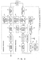
- Fig. 2 is a block diagram showing a recording and reproducing apparatus according to the present invention.
- a recording and reproducing apparatus 10 comprises recording apparatuses and reproducing apparatuses.
- the recording and reproducing apparatus 10 comprises the recording apparatuses including an external encoder 11, an interleaver 12, an internal encoder 13, a recording compensation setting circuit 14, a recording circuit 15 and a recording head 16, and the reproducing apparatuses including a reproducing head 18, an equalizer coefficient setting circuit 19, a partial response (PR) equalizer 20, a ⁇ setting circuit 21, an internal code APP (a posteriori probability) decoder 22, a deinterleaver 23, an external code APP decoder 24, an interleaver 25, a selector 26, a repetition time setting circuit 27, an error discriminator 28 and an error rate calculating circuit 29.
- the external encoder 11 and the internal encoder 13 are both recursive systematic convolutional encoders (RSC).
- the external encoder 11 receives data to be recorded in a medium 17 from a host system, and encodes the data.
- the interleaver 12 displaces randomly an array of codes outputted from the external encoder 11.
- the internal encoder 13 further encodes the codes displaced by the interleaver 12. Since the interleaver 12 is disposed between the external encoder 11 and the internal encoder 13, even if output series of the external encoder 11 have a minimum hamming weight, it is possible to decrease the probability that the output series of the internal encoder 13 again have the minimum hamming weight.
- the recording head 16 records the encoded data into the medium 17.
- the recording circuit 15 comprises a recording compensation circuit (not shown) for performing recording compensation.
- a recording compensation value of the recording compensation circuit is set by the recording compensation setting circuit 14.
- the reproducing head 18 read-in the encoded data from the recording medium 17.
- the PR equalizer 20 removes the effect of intersymbol interference from the encoded data read-in by the reproducing head 18, and outputs the results to the internal code APP circuit 22.
- the equalizer coefficient setting circuit 19 sets a coefficient used upon equalization to the PR equalizer 20.
- the internal code APP circuit 22 computes maximum posteriori probability of the internal code. As mentioned above, the data transmission channel value is required for decoding.
- the ⁇ setting circuit 21 sets ⁇ required for calculating the data transmission channel value at the internal code APP circuit 22.
- the ⁇ setting circuit 21 can change the ⁇ value.
- An inverse number of ⁇ 2 equals to the data transmission channel S/N. Therefore, the ⁇ setting circuit 21 may set the data transmission channel S/N.
- the ⁇ setting circuit 21 sets the ⁇ value, but there is no intention to limit the invention thereto.
- a data transmission channel S/N setting circuit for setting and changing the data transmission channel S/N may be disposed.
- the deinterleaver 23 performs reverse displacement as the interleaver 12.
- the external code APP decoder 24 computes maximum posteriori probability of the external code.
- the interleaver 25 displaces randomly an array of decoded results by the external code APP decoder 24.
- the results are inputted to the internal code APP circuit 22 and the selector 26.
- the outputs from the external code APP circuit 24 are used as preliminary information in the internal code APP circuit 22.
- the selector 26 outputs as a discrimination result the outputs from the external code APP circuit 24 under the conditions that the repetition time reach the upper limit, the log likelihood ratio per repetition time is sufficiently great and the like.
- the repetition time is set by the repetition time setting circuit 27.
- the discrimination result from the selector 26 is outputted to the host system and the error discriminator 28.
- the error discriminator 28 discriminates the presence or the absence of an error in the discrimination result.
- the error rate calculating circuit 29 calculates an error rate such as a bit error rate, an event error rate and the like based on an error discrimination result by the error discriminator 28.
- the data transmission channel S/N (or ⁇ value) is not calculated, but the ⁇ value is varied by the ⁇ setting circuit 21, and the error rate in each ⁇ value is calculated by the error rate calculating circuit 29.
- the ⁇ setting circuit 21 sets the ⁇ value obtained when the error rate becomes good as the optimal ⁇ value to be used upon decoding to the internal code APP circuit 22 of the recording and reproducing apparatus 10. Thus, it is possible to shorten the time required for calculating the data transmission channel S/N value. This method is based on the performance characteristic of the recording and reproducing apparatus 10 as described later.
- the ⁇ setting circuit 21 sets a ⁇ value other than the optimal ⁇ value to the internal code APP circuit 22, and the recording compensation setting circuit 14 varies the recording compensation value.
- the error rate calculating circuit 29 calculates the error rate in each recording compensation value.
- the recording compensation setting circuit 14 sets the recording compensation value obtained when the error rate becomes the optimal value as an optimal recording compensation value to the recording circuit 15. Thus, it is possible to shorten the time required for calculating the optimal recording compensation value.
- the ⁇ setting circuit 21 sets a ⁇ value other than the optimal ⁇ value to the internal code APP circuit 22, and the equalizer coefficient setting circuit 19 varies the equalizer coefficient.
- the error rate calculating circuit 29 calculates the error rate in each equalizer coefficient.
- the equalizer coefficient setting circuit 19 sets the equalizer coefficient obtained when the error rate becomes optimal as an optimal equalizer coefficient to the PR equalizer 20. Thus, it is also possible to shorten the time required for calculating the equalizer coefficient.
- the repetition time setting circuit 27 may vary the repetition time in the repetitive decoding. Thus, it is also possible to shorten the time required for calculating the optimal ⁇ value, the optimal recording compensation value and the optimal equalizer coefficient. This method is also based on the performance characteristic of the recording and reproducing apparatus 10 as described later.
- EER (error block number) / (decoding block number x 4096 bits)
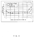
- the horizontal line represents an error between the data transmission channel S/N used when the data transmission channel value is calculated and the actual data transmission channel S/N (unit: dB), and the vertical line represents the required S/N.
- the error of the data transmission channel S/N is less than +-4 dB, the required S/N is substantially uniform, but when the error is greater than about +- 4 dB, the required S/N is significantly increased.
- the data transmission channel S/N can be represented using the ⁇ value. Therefore, the actual ⁇ value does not necessarily equal to the ⁇ value set at the recording and reproducing apparatus 10 for providing the required S/N.
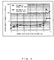
- the horizontal line represents the error of the data transmission channel S/N (unit: dB), and the vertical line represents the average error bit numbers (unit: number/error script).
- the error bit numbers are not increased, but when it is greater than 3 dB, the error bit numbers are significantly increased.
- the error between the actual data transmission channel S/N and the data transmission channel S/N set is less than about +-3 dB, the required S/N and the error rate are not significantly degraded.
- the ⁇ setting circuit 21 vary the ⁇ value set at the internal code APP circuit 22, and the error rate calculating circuit 29 calculates the error rate in each ⁇ value.
- the ⁇ setting circuit 21 determines the ⁇ value obtained when the error rate is best as the optimal ⁇ value, and sets the optimal ⁇ value at the internal code APP circuit 22.
- the optimal ⁇ value does not always equal to the actual ⁇ value.
- the required S/N is insensitive to the calculation error of the data transmission channel S/N. Therefore, it is considered that no problems occur in the recording and reproducing apparatus 10.
- the S/N value required when the data transmission channel S/N is greater than the actual value, and the S/N value required when the data transmission channel S/N is smaller than the actual value change substantially symmetrically at a center of 0 (zero) calculation error of the data transmission channel value. It is contemplated that an average value of the maximum and minimum values of the data transmission channel S/N that provide the same S/N required is proximate the value of the data transmission channel S/N when there is no calculation error.
- the ⁇ setting circuit 21 varies the ⁇ value set at the internal code APP circuit 22.
- the error rate calculating circuit 29 determines the maximum and minimum ⁇ values obtained when the predetermined upper limit error rate is satisfied.
- the ⁇ setting circuit 21 may take the average value of the maximum and minimum ⁇ values as the optimal ⁇ value.
- the optimal ⁇ value is determined based on the maximum and minimum ⁇ values that afford the bad error rate (upper limit error rate), thereby reducing the time required for determining the optimal ⁇ value.
- the ⁇ setting circuit 21 may read-out the optimal ⁇ value from the recording means upon using the recording and reproducing apparatus 10, and may set it to the internal code APP circuit 22.
- the optimal ⁇ value may be recorded in the recording medium 17.
- the ⁇ setting circuit 21 may read-out the optimal ⁇ value from the recording medium 17, and may set it to the internal code APP circuit 22.
- Fig. 5 there will be described a change in the bit error rate against the data transmission channel S/N when the calculation errors exist in different data transmission channels S/N.
- the horizontal line represents the S/N in the input of the internal code APP circuit (unit: dB), and the vertical line represents the bit error rate.
- the X marks represent the simulated result when no calculation error exists, and triangle-, square- and diamond-shaped marks represent the simulated results when the errors are 4 dB, 5 dB and 6 dB, respectively.
- the white marks represent the case that the S/N calculated exceeds the actual value, and the black marks represent the case that the S/N calculated is lower than the actual value.
- Fig. 6 shows a comparison of the bit error rate obtained when the data is decoded by superimposing the AWGN to the input of the internal code APP circuit using the repetitive decoding method at different repetition times and the bit error rate obtained when the input is decoded by the maximum likelihood decoding under the above-mentioned simulated conditions.
- the horizontal line represents the S/N in the input of the internal code APP circuit (unit: dB), and the vertical line represents the bit error rate.
- the diamond marks represent the simulated result when no repetition is made (similar to the maximum likelihood decoding), and square-, X-, triangle-, and round-shaped marks represent the simulated results when the repetition time is 1, 2, 5 and 20, respectively.
- the repetitive decoding method gives the decreased bit error rate as compared with that given by the maximum likelihood decoding method irrespective of the repetition time.
- the bit error rate is 10 -6
- the data transmission channel S/N obtained by the repetitive decoding method using one repetition time is improved by about 2 dB as compared with that obtained by the maximum likelihood decoding method.
- the bit error rate is 10 -6
- the data transmission channel S/N obtained by the repetitive decoding method using one repetition time is improved by about 2 dB as compared with that obtained by the maximum likelihood decoding method, and the data transmission channel S/N obtained by the repetitive decoding method using 5 repetition times is further improved by about 5.3 dB.
- the repetition time is increased, the percentage of the decreased bit error rate is decreased.
- the bit error rate is not so decreased, if the repetition time is over 5 and is further increased.
- the bit error rate is not so changed, when the result obtained by the repetitive decoding method using 5 repetition times is compared with the result obtained by the repetitive decoding method using 20 repetition times.
- Fig. 7 shows a comparison of the bit error rate obtained when the data is decoded by inputting a color noise to the internal code APP circuit using the repetitive decoding method at different repetition times and the bit error rate obtained when the data is decoded by the maximum likelihood decoding.
- the horizontal line represents the S/N in the input of the internal code APP circuit (unit: dB), and the vertical line represents the bit error rate, similar to Fig. 6.
- the repetitive decoding method gives the excellent bit error rate as compared with that given by the maximum likelihood decoding method. The more the repetition time is, the better the bit error rate of the repetitive decoding method is. The bit error rate is not so improved, if the repetition time is over a certain time.
- the error rate may be calculated such that the repetition time is set lower than that upon decoding. Thus, it is possible to further shorten the time required for determining the optimal ⁇ value error rate.
- the optimal ⁇ value when the calculation error of the data transmission channel S/N is increased, the error rate is degraded. Accordingly, after the optimal ⁇ value is determined, a ⁇ value other than the optimal ⁇ value is set, whereby the error rate can be degraded. With the bad error rate, while the recording compensation value is varied by the recording compensation value setting circuit 14, the error rate in each recording compensation value is calculated by the error rate calculating circuit 29.
- the recording compensation setting circuit 14 sets the recording compensation value that gives the best error rate as the optimal recording compensation value to the recording circuit 15.
- the bad error rate is provided by varying a ⁇ value other than the optimal ⁇ value.
- the recording compensation value is varied to calculate the error rate, whereby it is possible to shorten the time required for calculating the optimal recording compensation value.
- the error rate may be degraded by decreasing the repetition time, as described above. With this method, it is possible to shorten the time required for calculating the optimal recording compensation value.
- the optimal recording compensation value may be determined by varying ⁇ value other than the optimal ⁇ value, and decreasing the repetition time. In this case, it is also possible to shorten the time required for calculating the optimal recording compensation value.
- the means is substantially similar to the means for determining the optimal recording compensation value as described above.
- the bad error rate is provided by varying a ⁇ value other than the optimal ⁇ value and/or by decreasing the repetition time.
- the equalizer coefficient is varied to calculate the error rate in each equalizer coefficient.
- the equalizer coefficient that gives the best error rate is determined as the optimal equalizer coefficient. Thus, it is possible to shorten the time required for determining the optimal equalizer coefficient.
- the data transmission channel S/N is changed depending on the environmental temperature. Accordingly, it is required to optimize the ⁇ value set to the internal code APP circuit 22 depending on the environmental temperature.
- the optimal ⁇ value at each environmental temperature is determined as described above. Then, a table for storing the optimal ⁇ value corresponding to the environmental temperature is formed.
- the table is stored in the recording medium 17 or a recording means (not shown) such as a memory of the recording and reproducing apparatus 10.
- a temperature detector detects the environmental temperature, and the ⁇ setting circuit 21 reads-out the optimal ⁇ value corresponding to the environmental temperature from the recording medium 17 or the recording means to set the optimal ⁇ value at the internal code APP circuit 22.
- the optimal ⁇ value can be rapidly set to the internal code APP circuit 22 corresponding to the environmental temperature.
- a reference temperature which is environmental temperature of reference is determined.
- a table for storing a difference value between the optimal ⁇ value at the reference temperature and the optimal ⁇ value at the environmental temperature is formed.
- the table may be recorded in the recording medium 17 or the recording means.
- the recording and reproducing apparatus 10 utilizes SCCC in the above description
- other apparatus may utilize other code.
- the other apparatuses include a mobile phone, a broadcast transmitter/receiver and the like.
- the other codes include a PCCC, a low density parity check code and the like.
- the broadcast transmitter/receiver, the recording circuit 15, the recording compensation setting circuit 14, the recording head 16, the reproducing head 18, the PR equalizer 20 and the equalizer coefficient setting circuit 19 are not required.
- the mobile phone or the broadcast transmitter/receiver comprises a transmitter, an antenna and the like.
- a memory may store a program (firmware) for making a processor perform the process; the processor being incorporated in the recording and reproducing apparatus 10; and the process being performed by the ⁇ setting circuit 21, the equalizer coefficient setting circuit 19, the recording compensation setting circuit 14, the repetition time setting circuit 27 and the like.
- the S/N value or the ⁇ value of the data transmission channel are not calculated but are varied to calculate the error rate at each S/N value or ⁇ value of the data transmission channel. Based on the error rate, the optimal data transmission channel S/N or the optimal ⁇ value to be used upon decoding is determined. Thus, it is possible to rapidly provide the optimal data transmission channel S/N or the optimal ⁇ value.
- the ⁇ value or the repetition time is set to a value other than the optimal value to degrade the error rate. Then, the recording and reproducing parameter is varied and the error rate is calculated at each recording and reproducing parameter. Based on the error rate, the optimal recording and reproducing parameter and the like are determined, whereby it is possible to rapidly provide the recording and reproducing parameter.
- the decoding apparatus, the decoding circuit and the decoding method according to the present invention are suitable for applying to a reproducing apparatus of a data recorded in a recording medium such as a hard disk, and an apparatus for sending and receiving a encoded data, i.e., a mobile phone and broadcast transmitter/receiver.
Landscapes
- Engineering & Computer Science (AREA)
- Physics & Mathematics (AREA)
- Probability & Statistics with Applications (AREA)
- Theoretical Computer Science (AREA)
- Signal Processing (AREA)
- Error Detection And Correction (AREA)
- Detection And Correction Of Errors (AREA)
- Signal Processing For Digital Recording And Reproducing (AREA)
- Detection And Prevention Of Errors In Transmission (AREA)
Applications Claiming Priority (3)
| Application Number | Priority Date | Filing Date | Title |
|---|---|---|---|
| JP2002255778A JP3973026B2 (ja) | 2002-08-30 | 2002-08-30 | 復号装置、復号方法、及びその方法をプロセッサに行わせるプログラム |
| JP2002255778 | 2002-08-30 | ||
| PCT/JP2003/010953 WO2004023664A1 (ja) | 2002-08-30 | 2003-08-28 | 復号装置 |
Publications (2)
| Publication Number | Publication Date |
|---|---|
| EP1533908A1 true EP1533908A1 (de) | 2005-05-25 |
| EP1533908A4 EP1533908A4 (de) | 2007-05-30 |
Family
ID=31972915
Family Applications (1)
| Application Number | Title | Priority Date | Filing Date |
|---|---|---|---|
| EP03794122A Withdrawn EP1533908A4 (de) | 2002-08-30 | 2003-08-28 | Decodierungseinrichtung |
Country Status (5)
| Country | Link |
|---|---|
| EP (1) | EP1533908A4 (de) |
| JP (1) | JP3973026B2 (de) |
| KR (1) | KR100689009B1 (de) |
| CN (1) | CN1672331A (de) |
| WO (1) | WO2004023664A1 (de) |
Family Cites Families (11)
| Publication number | Priority date | Publication date | Assignee | Title |
|---|---|---|---|---|
| JP3451221B2 (ja) * | 1999-07-22 | 2003-09-29 | 日本無線株式会社 | 誤り訂正符号化装置、方法及び媒体、並びに誤り訂正符号復号装置、方法及び媒体 |
| DE19959409A1 (de) * | 1999-12-09 | 2001-06-21 | Infineon Technologies Ag | Turbo-Code-Decoder und Turbo-Code-Decodierverfahren mit iterativer Kanalparameterschätzung |
| FR2804260B1 (fr) * | 2000-01-21 | 2002-10-18 | Mitsubishi Electric Inf Tech | Procede de transmission numerique de type a codage correcteur d'erreurs |
| WO2001061867A1 (en) * | 2000-02-15 | 2001-08-23 | Kawasaki Steel Corporation | Turbo decoder |
| JP2001285084A (ja) * | 2000-03-31 | 2001-10-12 | Sony Corp | 符号化装置、符号化方法及び符号化プログラムが記録された記録媒体、並びに、復号装置、復号方法及び復号プログラムが記録された記録媒体 |
| JP2002111514A (ja) * | 2000-09-29 | 2002-04-12 | Hitachi Ltd | 誤り訂正符号化/復号方法、および誤り訂正符号化/復号装置 |
| JP3803239B2 (ja) * | 2000-09-29 | 2006-08-02 | 株式会社ルネサステクノロジ | 誤り訂正符号化及び復号装置 |
| US8014473B2 (en) * | 2001-01-26 | 2011-09-06 | Qualcomm Incorporated | Method and apparatus for detecting messages with unknown signaling characteristic |
| JP4191393B2 (ja) * | 2001-06-11 | 2008-12-03 | 富士通株式会社 | 情報記録再生装置及び方法並びに信号復号回路 |
| JP2003006993A (ja) * | 2001-06-25 | 2003-01-10 | Fujitsu Ltd | データ再生装置及びデータ記録再生装置 |
| US6885711B2 (en) * | 2001-06-27 | 2005-04-26 | Qualcomm Inc | Turbo decoder with multiple scale selections |
-
2002
- 2002-08-30 JP JP2002255778A patent/JP3973026B2/ja not_active Expired - Fee Related
-
2003
- 2003-08-28 KR KR1020057003253A patent/KR100689009B1/ko not_active Expired - Fee Related
- 2003-08-28 WO PCT/JP2003/010953 patent/WO2004023664A1/ja not_active Ceased
- 2003-08-28 EP EP03794122A patent/EP1533908A4/de not_active Withdrawn
- 2003-08-28 CN CNA038185180A patent/CN1672331A/zh active Pending
Also Published As
| Publication number | Publication date |
|---|---|
| KR100689009B1 (ko) | 2007-03-08 |
| KR20050059113A (ko) | 2005-06-17 |
| JP2004096481A (ja) | 2004-03-25 |
| WO2004023664A1 (ja) | 2004-03-18 |
| CN1672331A (zh) | 2005-09-21 |
| JP3973026B2 (ja) | 2007-09-05 |
| EP1533908A4 (de) | 2007-05-30 |
Similar Documents
| Publication | Publication Date | Title |
|---|---|---|
| KR101337736B1 (ko) | 에러 정정 성능 조정 시스템, 디스크 드라이브 테스트 방법 및 디스크 드라이브 테스트 시스템 | |
| US20050149819A1 (en) | Three-dimensional error correction method | |
| US20080263430A1 (en) | Data readout device and data readout method | |
| EP0854581A2 (de) | Kodierungs- und Dekodierungsanordnung mit CRC-Prüfbit | |
| US20070061687A1 (en) | Soft decoding method and apparatus, error correction method and apparatus, and soft output method and apparatus | |
| JP3887255B2 (ja) | 反復復号を用いたデータ処理装置 | |
| US8271863B2 (en) | Forward decision aided nonlinear Viterbi detector | |
| US7414551B2 (en) | Encoding and decoding methods and apparatuses for recording system | |
| US7095698B2 (en) | Data recording device and data reproducing device | |
| US7430705B2 (en) | Data recording and reproducing system, and data recording and reproducing method | |
| EP1533908A1 (de) | Decodierungseinrichtung | |
| US20050111593A1 (en) | Decoding apparatus | |
| JP4224370B2 (ja) | 入力制御装置及び入力制御方法 | |
| Divsalar et al. | Upper bounds to error probabilities of coded systems over AWGN and fading channels | |
| JP4071771B2 (ja) | データ記録再生装置及び方法 | |
| JP4006446B2 (ja) | データ記録再生システム | |
| US20070127728A1 (en) | Iterative decoding apparatus and method | |
| KR100725082B1 (ko) | 반복 복호를 이용한 데이터 기록 재생 장치 및 방법 | |
| JP2004310807A (ja) | パラメータ調整方法、信号処理装置 | |
| JP2005018892A (ja) | データ記録再生信号処理装置 | |
| JP2005108332A (ja) | 反復復号を用いたデータ再生装置及び方法 |
Legal Events
| Date | Code | Title | Description |
|---|---|---|---|
| PUAI | Public reference made under article 153(3) epc to a published international application that has entered the european phase |
Free format text: ORIGINAL CODE: 0009012 |
|
| 17P | Request for examination filed |
Effective date: 20050117 |
|
| AK | Designated contracting states |
Kind code of ref document: A1 Designated state(s): AT BE BG CH CY CZ DE DK EE ES FI FR GB GR HU IE IT LI LU MC NL PT RO SE SI SK TR |
|
| RBV | Designated contracting states (corrected) |
Designated state(s): DE FR GB |
|
| A4 | Supplementary search report drawn up and despatched |
Effective date: 20070503 |
|
| RIC1 | Information provided on ipc code assigned before grant |
Ipc: G11B 20/14 20060101ALI20070425BHEP Ipc: G11B 20/10 20060101ALI20070425BHEP Ipc: H03M 13/29 20060101AFI20040320BHEP |
|
| STAA | Information on the status of an ep patent application or granted ep patent |
Free format text: STATUS: THE APPLICATION IS DEEMED TO BE WITHDRAWN |
|
| 18D | Application deemed to be withdrawn |
Effective date: 20070802 |