EP1533888A1 - Pwm inverter control device and control method - Google Patents
Pwm inverter control device and control method Download PDFInfo
- Publication number
- EP1533888A1 EP1533888A1 EP03733290A EP03733290A EP1533888A1 EP 1533888 A1 EP1533888 A1 EP 1533888A1 EP 03733290 A EP03733290 A EP 03733290A EP 03733290 A EP03733290 A EP 03733290A EP 1533888 A1 EP1533888 A1 EP 1533888A1
- Authority
- EP
- European Patent Office
- Prior art keywords
- level
- bus voltage
- reference value
- state
- output
- Prior art date
- Legal status (The legal status is an assumption and is not a legal conclusion. Google has not performed a legal analysis and makes no representation as to the accuracy of the status listed.)
- Withdrawn
Links
Images


Classifications
-
- H—ELECTRICITY
- H02—GENERATION; CONVERSION OR DISTRIBUTION OF ELECTRIC POWER
- H02M—APPARATUS FOR CONVERSION BETWEEN AC AND AC, BETWEEN AC AND DC, OR BETWEEN DC AND DC, AND FOR USE WITH MAINS OR SIMILAR POWER SUPPLY SYSTEMS; CONVERSION OF DC OR AC INPUT POWER INTO SURGE OUTPUT POWER; CONTROL OR REGULATION THEREOF
- H02M7/00—Conversion of AC power input into DC power output; Conversion of DC power input into AC power output
- H02M7/42—Conversion of DC power input into AC power output without possibility of reversal
- H02M7/44—Conversion of DC power input into AC power output without possibility of reversal by static converters
- H02M7/48—Conversion of DC power input into AC power output without possibility of reversal by static converters using discharge tubes with control electrode or semiconductor devices with control electrode
- H02M7/505—Conversion of DC power input into AC power output without possibility of reversal by static converters using discharge tubes with control electrode or semiconductor devices with control electrode using devices of a thyratron or thyristor type requiring extinguishing means
- H02M7/515—Conversion of DC power input into AC power output without possibility of reversal by static converters using discharge tubes with control electrode or semiconductor devices with control electrode using devices of a thyratron or thyristor type requiring extinguishing means using semiconductor devices only
- H02M7/525—Conversion of DC power input into AC power output without possibility of reversal by static converters using discharge tubes with control electrode or semiconductor devices with control electrode using devices of a thyratron or thyristor type requiring extinguishing means using semiconductor devices only with automatic control of output waveform or frequency
- H02M7/527—Conversion of DC power input into AC power output without possibility of reversal by static converters using discharge tubes with control electrode or semiconductor devices with control electrode using devices of a thyratron or thyristor type requiring extinguishing means using semiconductor devices only with automatic control of output waveform or frequency by pulse width modulation
-
- H—ELECTRICITY
- H02—GENERATION; CONVERSION OR DISTRIBUTION OF ELECTRIC POWER
- H02M—APPARATUS FOR CONVERSION BETWEEN AC AND AC, BETWEEN AC AND DC, OR BETWEEN DC AND DC, AND FOR USE WITH MAINS OR SIMILAR POWER SUPPLY SYSTEMS; CONVERSION OF DC OR AC INPUT POWER INTO SURGE OUTPUT POWER; CONTROL OR REGULATION THEREOF
- H02M7/00—Conversion of AC power input into DC power output; Conversion of DC power input into AC power output
- H02M7/42—Conversion of DC power input into AC power output without possibility of reversal
- H02M7/44—Conversion of DC power input into AC power output without possibility of reversal by static converters
- H02M7/48—Conversion of DC power input into AC power output without possibility of reversal by static converters using discharge tubes with control electrode or semiconductor devices with control electrode
- H02M7/483—Converters with outputs that each can have more than two voltages levels
-
- H—ELECTRICITY
- H02—GENERATION; CONVERSION OR DISTRIBUTION OF ELECTRIC POWER
- H02M—APPARATUS FOR CONVERSION BETWEEN AC AND AC, BETWEEN AC AND DC, OR BETWEEN DC AND DC, AND FOR USE WITH MAINS OR SIMILAR POWER SUPPLY SYSTEMS; CONVERSION OF DC OR AC INPUT POWER INTO SURGE OUTPUT POWER; CONTROL OR REGULATION THEREOF
- H02M1/00—Details of apparatus for conversion
- H02M1/32—Means for protecting converters other than automatic disconnection
-
- H—ELECTRICITY
- H02—GENERATION; CONVERSION OR DISTRIBUTION OF ELECTRIC POWER
- H02M—APPARATUS FOR CONVERSION BETWEEN AC AND AC, BETWEEN AC AND DC, OR BETWEEN DC AND DC, AND FOR USE WITH MAINS OR SIMILAR POWER SUPPLY SYSTEMS; CONVERSION OF DC OR AC INPUT POWER INTO SURGE OUTPUT POWER; CONTROL OR REGULATION THEREOF
- H02M1/00—Details of apparatus for conversion
- H02M1/36—Means for starting or stopping converters
-
- H—ELECTRICITY
- H02—GENERATION; CONVERSION OR DISTRIBUTION OF ELECTRIC POWER
- H02M—APPARATUS FOR CONVERSION BETWEEN AC AND AC, BETWEEN AC AND DC, OR BETWEEN DC AND DC, AND FOR USE WITH MAINS OR SIMILAR POWER SUPPLY SYSTEMS; CONVERSION OF DC OR AC INPUT POWER INTO SURGE OUTPUT POWER; CONTROL OR REGULATION THEREOF
- H02M7/00—Conversion of AC power input into DC power output; Conversion of DC power input into AC power output
- H02M7/42—Conversion of DC power input into AC power output without possibility of reversal
- H02M7/44—Conversion of DC power input into AC power output without possibility of reversal by static converters
- H02M7/48—Conversion of DC power input into AC power output without possibility of reversal by static converters using discharge tubes with control electrode or semiconductor devices with control electrode
-
- H—ELECTRICITY
- H02—GENERATION; CONVERSION OR DISTRIBUTION OF ELECTRIC POWER
- H02M—APPARATUS FOR CONVERSION BETWEEN AC AND AC, BETWEEN AC AND DC, OR BETWEEN DC AND DC, AND FOR USE WITH MAINS OR SIMILAR POWER SUPPLY SYSTEMS; CONVERSION OF DC OR AC INPUT POWER INTO SURGE OUTPUT POWER; CONTROL OR REGULATION THEREOF
- H02M7/00—Conversion of AC power input into DC power output; Conversion of DC power input into AC power output
- H02M7/42—Conversion of DC power input into AC power output without possibility of reversal
- H02M7/44—Conversion of DC power input into AC power output without possibility of reversal by static converters
- H02M7/48—Conversion of DC power input into AC power output without possibility of reversal by static converters using discharge tubes with control electrode or semiconductor devices with control electrode
- H02M7/483—Converters with outputs that each can have more than two voltages levels
- H02M7/487—Neutral point clamped inverters
Definitions
- the present invention relates to a PWM inverter control apparatus and more particularly to a multilevel PWM inverter control apparatus in which four switching units are connected in series for each layer between a DC bus voltage having a plus level and a DC bus voltage having a minus level.
- a PWM inverter control apparatus In order to control the rotating speed of an AC motor, a PWM inverter control apparatus has widely been used. In the case in which the output current of the PWM inverter control apparatus is increased for some abnormality, it is necessary to limit the output current or to carry out a protecting operation in order to obtain the safety of the PWM inverter control apparatus and the safety of equipment to be connected as a load. In order to implement such a protecting operation, conventionally, the safety has been ensured by using a base block operation for cutting off a gate signal to control ON/OFF of a switching unit and bringing all of the switching units into an OFF state, thereby carrying out a protection.
- Step 41 the output current is detected and a current value thereof is set to be I (Step 41), and the current value I is compared with a preset reference value I th (Step 42).
- Step 42 a normal run is carried out (Step 43) if the current value I is smaller than the reference value I th , and a base block operation is carried out (Step 44) if the current value I is equal to or greater than the reference value I th .
- Step 44 the current value I is compared with the reference value I th in the same manner and the base block operation is continuously carried out until the current value I is smaller than the reference value I th .
- the multilevel PWM inverter control apparatus In the multilevel PWM inverter control apparatus, only a voltage which is a half of the voltage of a DC power supply is applied to both ends of each switching unit. For this reason, the breakdown voltage of each switching unit is a half of the voltage of the DC power supply. When the voltage of the DC power supply is exactly applied to both ends, an overvoltage breakdown is caused. In such a multilevel PWM inverter control apparatus, a large number of switching units are to be switched so that a structure is complicated. Therefore, a problem arises in the case in which the protecting operation is carried out through a base block.
- This problem is that the operation timing of each switching unit is shifted when the normal operation is changed to the base block operation and when the base block operation is changed to the normal operation, and a voltage which is at least a double of a normal voltage is applied to one switching unit, resulting in the generation of the overvoltage breakdown.
- the voltage of the DC power supply is exactly applied to the residual switching unit so that a breakdown is caused.
- JP-A-10-164854 publication there has been proposed a method of detecting an abnormal state when a switching unit is broken down due to a power short circuit or an overcurrent and delaying a timing for cutting off a specific switching unit in order to prevent the further breakdown of the switching unit due to an overvoltage.
- the conventional multilevel PWM inverter control apparatus has the following problems.
- the invention provides a PWM inverter control apparatus in which four switching units are connected in series for each phase between a DC bus voltage having a plus level and a DC bus voltage having a minus level, comprising:
- the base block operation or the emergency stop operation is always carried out after the zero vector state to be started from an 000 state is brought. If the state of the switching unit which is obtained immediately before the execution of a protecting operation is any of P, N and O, therefore, a change in a voltage is reduced to a half of the voltage of a DC power supply so that the switching unit can be prevented from being broken down due to an overvoltage.
- the states of P, N and O are used also in a normal operation. Therefore, it is possible to smoothly carry out a reset from a zero vector state of PPP, 000 or NNN to a normal operation and to perform the protecting operation without requiring a complicated algorithm.
- the controller may carry out a reset to a normal operation after performing a zero vector output operation when executing the reset to the normal operation after carrying out the base block operation.
- a zero vector output operation is always performed. Therefore, it is possible to prevent the switching unit from being broken down due to an overvoltage when carrying out the reset from the protecting operation to the normal operation.
- the invention provides a PWM inverter control apparatus in which four switching units are connected in series for each phase between a DC bus voltage having a plus level and a DC bus voltage having a minus level, comprising:
- setting is carried out to always bring a zero vector state started from an 000 state when performing a reset from the protecting operation to the normal operation. In the switching from the normal operation to the protecting operation and the reset from the protecting operation to the normal operation, therefore, it is possible to prevent the switching unit from being broken down due to an overvoltage.
- the zero vector may be started from an 000 state in which all of the phases are turned ON by the second and third switching units from the DC bus voltage side having the plus level to output the intermediate potential to be the voltage between the plus and minus levels of the DC bus voltage, and may be always brought into the 000 state between a PPP state in which all of the phases are turned ON by first and second switching units from the DC bus voltage side having the plus level to output the plus level of the DC bus voltage and an NNN state in which all of the phases are turned ON by third and fourth switching units from the DC bus voltage side having the plus level to output the minus level of the DC bus voltage.
- 1 denotes a controller
- 2 denotes a current detecting circuit
- 3 denotes a DC power supply
- 41 to 44 denote a step
- 11 and 12 denote a voltage dividing capacitor
- 101 to 112 denote a switching unit
- 201 to 212 denote a free wheel diode
- 301 to 306 denote a clamp diode.
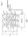
- Fig. 1 is a block diagram showing the structure of a PWM inverter control apparatus according to a first embodiment of the invention.
- the PWM inverter control apparatus is constituted by a controller 1, a current detecting circuit 2, a DC power supply 3, smoothing capacitors 11 and 12, switching units 101 to 112, free wheel diodes 201 to 212, and intermediate level outputting clamp diodes 301 to 306.
- the controller 1 controls a gate signal input to the gate of each of the switching units 101 to 112, thereby controlling the timing of ON/OFF of each of the switching units 101 to 112.
- the current detecting circuit 2 measures the current value of a current output from the PWM inverter control apparatus.
- a positive voltage is output when the switching units 101 and 102 are turned ON
- an intermediate potential is output when the switching units 102 and 103 are turned ON
- a negative voltage is output when the switching units 103 and 104 are turned ON.
- a state in which two upper switching units S1 and S2 are turned ON is represented as a P state in which the plus level of a DC bus voltage is output
- a state in which two middle switching units S2 and S3 are turned ON is represented as an 0 state in which a neutral voltage subjected to capacitor dividing is output
- a state in which two lower switching units S3 and S4 are turned ON is represented as an N state in which the minus level of a DC bus is output.
- the controller 1 brings the state of each phase into a state of P, N or O during a normal operation, thereby controlling an output voltage to a motor.
- the controller 1 controls each switching unit to bring a zero vector state, thereby protecting each switching unit and equipment to be connected.
- the zero vector state implies a state in which the output voltage of each phase is set to have the same level.
- the zero vector state includes three types of states of PPP, 000 and NNN.
- the PWM inverter control apparatus has features in only the control algorithm of the controller 1 and other circuit structures are the same as those in a conventional multilevel PWM inverter control apparatus, detailed description thereof will be omitted.
- an output current is detected by the current detecting circuit 2 and a current value thereof is set to be I (Step 21), and the controller 1 compares the current value I with a first reference value I 1 which is preset (Step 22). If the current value I is smaller than the first reference value I 1 at the Step 22, the controller 1 carries out a normal run (Step 23). If the current value I is equal to or greater than the first reference value I 1 at the Step 22, the controller 1 stops the normal operation and switching to an operation for outputting a zero vector is carried out for a safety.
- the controller 1 switches the vectors of PPP, 000 and NNN in order and outputs them, and sets to always output the zero vector from the 000 when carrying out the switching to the operation for outputting the zero vector.
- the reason is as follows. A pulse pattern obtained immediately before outputting the zero vector cannot be predicted. In the case in which the PPP and the NNN are output at the beginning when the switching to the operation for outputting the zero vector is carried out, therefore, a voltage to be applied to the switching unit is suddenly changed and the ON/OFF timing of the switching unit is varied. Consequently, a full voltage is applied to one switching unit in the worst state, resulting in the breakdown of equipment.
- a voltage is changed from a plus level to a minus level so that a fluctuation in a voltage corresponding to the voltage of the DC power supply 3 is generated when the state of the switching units for the same phase is brought into the N state as a protecting operation.
- a voltage is changed from the minus level to the plus level so that a fluctuation in the voltage corresponding to the voltage of the DC power supply 3 is generated when the states of the switching units for the same phase are brought into the P state as a protecting operation.
- a change in a voltage is a half of the voltage of the DC power supply 3 at a maximum when a state obtained immediately therebefore is any of P, N and O. Even if the ON/OFF timing of the switching unit is varied, thus, only the half of the voltage of the DC power supply 3 is applied to one switching unit.
- the vector of the 000 is set to be output before or after the output of the zero vector of the PPP or NNN, which is safer.
- the controller 1 outputs the zero vector at Step 24 and then compares the output current value I which is detected with a second reference value I 2 (Step 25). If the current value I is smaller than the second reference value I 2 at the Step 25, an operation for outputting the zero vector is continuously carried out (Step 26) and a return to the processing of carrying out a comparison with the first comparison value I 1 is performed (Step 22). If the current value I is smaller than the first reference value I 1 at the Step 22, a reset to the normal run is carried out (Step 23). If the current value I is equal to or greater than the first reference value I 1 , the operation for outputting the zero vector is continuously carried out. If the current value I is equal to or greater than the first reference value I 1 and is smaller than the second reference value I 2 , accordingly, the zero vector is continuously output.
- the controller 1 compares the current value I with a third reference value I 3 (Step 27). If the current value I is smaller than the third reference value I 3 at the Step 27, the controller 1 carries out a base block operation for stopping the operations of all of the switching units 101 to 112 (Step 28). After the processing of the Step 28, then, a return to the processing of comparing the current value I with the second comparison value I 2 is carried out (Step 25) and the same processing as that described above is executed. If the current value I is equal to or greater than the second reference value I 2 , the base block operation is continuously carried out. If the current I is equal to or greater than the second reference value I 2 and is smaller than the third reference value I 3 , accordingly, the controller 1 continuously carries out the base block operation.
- Step 29 In the comparison of the current value I with the third reference value I 3 at the Step 27, if the current value I which is detected is equal to or greater than the third reference value I 3 , the controller 1 stops the operation of the inverter as a final protection and gives an alarm to confirm a whole safety and to carry out restarting (Step 29).
- the controller 1 is set to carry out the base block operation at the Step 28, and thereafter, to always return the normal operation through the operation for outputting the zero vector at the Step 26 without directly performing the reset to the normal operation.
- the first reference value I 1 is set to have a slightly higher level than the level of a rated current value. In other words, while the first reference value I 1 exceeds the rated current value due to a sudden acceleration/deceleration or a fluctuation in a load, it is permitted in a short time. Accordingly, the controller 1 waits for the current value I to be decreased while outputting the zero vector, and returns to the normal operation if the current value I is smaller than the first reference value I 1 .
- the vector itself in the P, N and O states is also output during a normal run. Therefore, this operation can be grasped as a part of the normal run. Therefore, it is possible to smoothly carry out the reset from the protecting operation to the normal run.
- the second reference value I 2 has a higher level than the level of the first reference value I 1 , moreover, it is permitted in a very short time.
- a state in which the current value I is equal to or greater than the second reference value I 2 is generated when an operation exceeding the capability of equipment is to be carried out or due to a sudden change in a load.
- the controller 1 does not bring the zero vector state in which the output current cannot be reduced rapidly but carries out the protecting operation using the base block.
- the third reference value I 3 has a higher level than the level of the second reference value I 2 .
- the current value I is equal to or greater than the third reference value I 3 .
- some abnormality is generated and it is necessary to carry out a release after confirming a safety. Therefore, the equipment itself is not automatically reset. This state will be hereinafter referred to as an emergency stop.
- the first to third reference values I 1 to I 3 are set and the method of the protecting operation is switched depending on the measured current value I in such a manner that a reset to the normal run can be carried out immediately in case of a slight abnormality and the operation can be stopped instantly to ensure the safety in case of a serious abnormality. More specifically, in the case in which a load to be connected to the equipment is operated, it is necessary to meet a demand for safely carrying out a stop operation when some accident is caused without interrupting the run as much as possible.
- the base block operation or the emergency stop operation is always executed after the zero vector state is brought. Setting is carried out to first bring the 000 state in the switching from the normal operation to the zero vector state. Even if the state of the switching unit which is obtained immediately before the execution of the protecting operation is any of P, N and 0, therefore, a change in a voltage is reduced to be a half of the voltage of the DC power supply 3 so that the switching unit can be prevented from being broken down due to an overvoltage.
- the zero vector output operation is always carried out in the execution of the reset from the protecting operation to the normal operation. Therefore, it is possible to prevent the switching unit from being broken down due to an overvoltage in the execution of the reset from the protecting operation to the normal operation.
- the PWM inverter control apparatus is different from the PWM inverter control apparatus according to the first embodiment shown in Fig. 1 in respect of only the control algorithm of a controller 1. In the following, therefore, the operation of the PWM inverter control apparatus according to the embodiment will be described with reference to a flowchart of Fig. 3.
- an output current is detected by a current detecting circuit 2 and a current value thereof is set to be I (Step 31), and the controller 1 compares the current value I with the second reference value I 2 (Step 32). If the current value I is smaller than the second reference value I 2 at the Step 32, the controller 1 carries out a normal run (Step 33). If the current value I is equal to or greater than the second reference value I 2 at the Step 32, the controller 1 stops the normal operation and outputs a zero vector for a safety (Step 34). Herein, the controller 1 may output only an 000 vector in a zero vector. Next, the controller 1 carries out a protecting operation using a base block (Step 35).
- Step 36 the comparison of the current value I and the second reference value I 2 is carried out again. If the current value I is equal to or greater than the reference value I 2 , the base block operation is continuously carried out. If the current value I is smaller than the second reference value I 2 at the Step 36, the controller 1 outputs the zero vector (Step 37) and is thereafter returned to the normal run (the Step 33). In the same manner as in the Step 34, only the 000 vector in the zero vector may be output. By the execution of such a processing, the controller 1 is set to always carry out the operation for outputting the zero vector before a reset from the protecting operation to the normal operation.
- the embodiment supposes an application to a multilevel PWM inverter control apparatus in the case in which a motor connected to equipment having a small number of functions and a simple structure is to be controlled. For this reason, the base block operation is carried out instantly when an overcurrent is simply detected, and the zero vector started from OOO immediately before and after the base block operation is output when a reset from the base block operation to the normal run is to be performed.
- a third reference value I 3 may be provided as a final protection and the inverter may be operated to emergently stop as the final protection or a time required for operating the base block may be integrated and an emergency stop may be carried out after the operation is continuously performed for a certain period or more.
- JP-A-2002-171256 filed on June 12, 2002 and contents thereof are incorporated by reference.
- the multilevel PWM inverter control apparatus it is possible to produce an advantage that switching from a normal operation to a protecting operation can be safely carried out without requiring a complicated control algorithm, and furthermore, the safety of an inverter body can be ensured and a smooth reset from the protecting operation to the normal operation can be performed when the reset is to be executed, and a power can also be supplied safely to equipment to be connected as a load.
Landscapes
- Engineering & Computer Science (AREA)
- Power Engineering (AREA)
- Inverter Devices (AREA)
Abstract
It is an object of the invention to provide a multilevel PWM inverter control apparatus capable of safely carrying out switching from a normal operation to a protecting operation and performing a reset from the protecting operation to the normal run safely and smoothly without requiring a complicated control algorithm. <??>In the invention, if a current value I which is measured is set to have a level which is equal to or higher than the level of a first reference value I1 and is lower than the level of a second reference value I2, a zero vector to be started from an 000 state in which an intermediate potential is output for all of phases is output (Step 22). If the current value I is set to have a level which is equal to or higher than the level of the second reference value I2 and is lower than the level of a third reference value I3, a base block operation for bringing all of switching units into an OFF state is carried out after outputting the zero vector (Step 28). If the current value I is equal to or greater than the third reference value I3, an emergency stop is carried out (Step 29). when a reset to a normal operation is carried out after the execution of the base block operation, the reset to the normal operation is performed after the execution of the operation for outputting the zero vector. <IMAGE>
Description
The present invention relates to a PWM inverter control
apparatus and more particularly to a multilevel PWM inverter
control apparatus in which four switching units are connected
in series for each layer between a DC bus voltage having a plus
level and a DC bus voltage having a minus level.
In order to control the rotating speed of an AC motor,
a PWM inverter control apparatus has widely been used. In the
case in which the output current of the PWM inverter control
apparatus is increased for some abnormality, it is necessary
to limit the output current or to carry out a protecting
operation in order to obtain the safety of the PWM inverter
control apparatus and the safety of equipment to be connected
as a load. In order to implement such a protecting operation,
conventionally, the safety has been ensured by using a base
block operation for cutting off a gate signal to control ON/OFF
of a switching unit and bringing all of the switching units into
an OFF state, thereby carrying out a protection.
An operation for detecting the abnormality of an output
current to carry out a protection in such a conventional PWM
inverter control apparatus is shown in a flowchart of Fig. 4.
First of all, the output current is detected and a current value
thereof is set to be I (Step 41), and the current value I is
compared with a preset reference value Ith (Step 42). At the
Step 42, a normal run is carried out (Step 43) if the current
value I is smaller than the reference value Ith, and a base block
operation is carried out (Step 44) if the current value I is
equal to or greater than the reference value Ith. When a next
control cycle comes, the current value I is compared with the
reference value Ith in the same manner and the base block
operation is continuously carried out until the current value
I is smaller than the reference value Ith.
According to such a conventional PWM inverter control
apparatus, in the case in which some abnormality is generated
so that an output current is increased, the base block operation
is carried out so that the protecting operation is performed.
However, there has been proposed a multilevel PWM inverter
control apparatus for switching an output voltage among three
levels having a positive, an intermediate potential and a
negative in order to reduce a harmonic component which is
generated in addition to a PWM inverter control apparatus for
switching an output voltage between two levels having the
positive and the negative.
In the multilevel PWM inverter control apparatus, only
a voltage which is a half of the voltage of a DC power supply
is applied to both ends of each switching unit. For this reason,
the breakdown voltage of each switching unit is a half of the
voltage of the DC power supply. When the voltage of the DC power
supply is exactly applied to both ends, an overvoltage breakdown
is caused. In such a multilevel PWM inverter control apparatus,
a large number of switching units are to be switched so that
a structure is complicated. Therefore, a problem arises in the
case in which the protecting operation is carried out through
a base block. This problem is that the operation timing of each
switching unit is shifted when the normal operation is changed
to the base block operation and when the base block operation
is changed to the normal operation, and a voltage which is at
least a double of a normal voltage is applied to one switching
unit, resulting in the generation of the overvoltage breakdown.
For example, in the case in which three of the four
switching units connected in series are turned ON at the same
time, the voltage of the DC power supply is exactly applied to
the residual switching unit so that a breakdown is caused.
In order to prevent such a bad influence, as described
in JP-A-10-164854 publication, there has been proposed a method
of detecting an abnormal state when a switching unit is broken
down due to a power short circuit or an overcurrent and delaying
a timing for cutting off a specific switching unit in order to
prevent the further breakdown of the switching unit due to an
overvoltage.
According to such a method of delaying a timing for cutting
off a specific switching unit, it is possible to prevent the
breakdown of the switching unit to protect an apparatus. In
the case in which a multilevel PWM inverter control apparatus
is to be protected safely and a smooth reset to a normal run
is to be implemented, however, it is necessary to carry out a
control in a very complicated timing.
In the case in which an abnormality such as an overcurrent
which is detected is temporarily caused, moreover, a smooth
reset from the protecting operation to the normal operation is
required. However, it is hard to smoothly carry out the reset
to the normal operation in the protecting method using a base
block in which all of the switching units are turned OFF, and
furthermore, a protecting method of delaying a timing for
cutting off a specific switching unit.
The conventional multilevel PWM inverter control
apparatus has the following problems.
It is an object of the invention to provide a multilevel
PWM inverter control apparatus which can implement, in a simple
algorithm, a protecting operation capable of safely carrying
out switching from a normal operation to a protecting operation
and ensuring the safety of an inverter body also when performing
a reset from the protecting operation to the normal run, and
furthermore, safely supplying a power to equipment to be
connected as a load.
In order to attain the object, the invention provides a
PWM inverter control apparatus in which four switching units
are connected in series for each phase between a DC bus voltage
having a plus level and a DC bus voltage having a minus level,
comprising:
According to the invention, when a current value I
detected by the current detecting circuit is equal to or greater
than a first current value, the base block operation or the
emergency stop operation is always carried out after the zero
vector state to be started from an 000 state is brought. If
the state of the switching unit which is obtained immediately
before the execution of a protecting operation is any of P, N
and O, therefore, a change in a voltage is reduced to a half
of the voltage of a DC power supply so that the switching unit
can be prevented from being broken down due to an overvoltage.
Moreover, the states of P, N and O are used also in a normal
operation. Therefore, it is possible to smoothly carry out a
reset from a zero vector state of PPP, 000 or NNN to a normal
operation and to perform the protecting operation without
requiring a complicated algorithm.
Furthermore, the controller may carry out a reset to a
normal operation after performing a zero vector output
operation when executing the reset to the normal operation after
carrying out the base block operation.
According to the invention, when a reset from the
protecting operation to the normal operation is to be carried
out, a zero vector output operation is always performed.
Therefore, it is possible to prevent the switching unit from
being broken down due to an overvoltage when carrying out the
reset from the protecting operation to the normal operation.
Moreover, the invention provides a PWM inverter control
apparatus in which four switching units are connected in series
for each phase between a DC bus voltage having a plus level and
a DC bus voltage having a minus level, comprising:
According to the invention, when the normal operation is
switched to the protecting operation based on the base block
operation, setting is carried out to always bring a zero vector
state started from an 000 state when performing a reset from
the protecting operation to the normal operation. In the
switching from the normal operation to the protecting operation
and the reset from the protecting operation to the normal
operation, therefore, it is possible to prevent the switching
unit from being broken down due to an overvoltage.
In addition, the zero vector may be started from an 000
state in which all of the phases are turned ON by the second
and third switching units from the DC bus voltage side having
the plus level to output the intermediate potential to be the
voltage between the plus and minus levels of the DC bus voltage,
and
may be always brought into the 000 state between a PPP state in which all of the phases are turned ON by first and second switching units from the DC bus voltage side having the plus level to output the plus level of the DC bus voltage and an NNN state in which all of the phases are turned ON by third and fourth switching units from the DC bus voltage side having the plus level to output the minus level of the DC bus voltage.
may be always brought into the 000 state between a PPP state in which all of the phases are turned ON by first and second switching units from the DC bus voltage side having the plus level to output the plus level of the DC bus voltage and an NNN state in which all of the phases are turned ON by third and fourth switching units from the DC bus voltage side having the plus level to output the minus level of the DC bus voltage.
In the drawings, 1 denotes a controller, 2 denotes a
current detecting circuit, 3 denotes a DC power supply, 41 to
44 denote a step, 11 and 12 denote a voltage dividing capacitor,
101 to 112 denote a switching unit, 201 to 212 denote a free
wheel diode, and 301 to 306 denote a clamp diode.
Next, embodiments of the invention will be described in
detail with reference to the drawings.
Fig. 1 is a block diagram showing the structure of a PWM
inverter control apparatus according to a first embodiment of
the invention.
The PWM inverter control apparatus according to the
embodiment is constituted by a controller 1, a current detecting
circuit 2, a DC power supply 3, smoothing capacitors 11 and 12,
switching units 101 to 112, free wheel diodes 201 to 212, and
intermediate level outputting clamp diodes 301 to 306.
The controller 1 controls a gate signal input to the gate
of each of the switching units 101 to 112, thereby controlling
the timing of ON/OFF of each of the switching units 101 to 112.
The current detecting circuit 2 measures the current value of
a current output from the PWM inverter control apparatus.
In the PWM inverter control apparatus, four switching
units are connected in series for each phase. In a circuit
constituted by the four switching units 101 to 104, for example,
a positive voltage is output when the switching units 101 and
102 are turned ON, an intermediate potential is output when the
switching units 102 and 103 are turned ON, and a negative voltage
is output when the switching units 103 and 104 are turned ON.
In the following description, assuming that four of the
switching units 101 to 112 which are connected in series make
a set to be a phase and are indicated as S1, S2, S3 and S4 from
an upper side, a state in which two upper switching units S1
and S2 are turned ON is represented as a P state in which the
plus level of a DC bus voltage is output, a state in which two
middle switching units S2 and S3 are turned ON is represented
as an 0 state in which a neutral voltage subjected to capacitor
dividing is output, and a state in which two lower switching
units S3 and S4 are turned ON is represented as an N state in
which the minus level of a DC bus is output.
The controller 1 according to the embodiment brings the
state of each phase into a state of P, N or O during a normal
operation, thereby controlling an output voltage to a motor.
In the embodiment, when carrying out a protecting operation,
the controller 1 controls each switching unit to bring a zero
vector state, thereby protecting each switching unit and
equipment to be connected. The zero vector state implies a
state in which the output voltage of each phase is set to have
the same level. In the case in which a three-phase multilevel
PWM inverter control apparatus is taken as an example and each
phase is described in order, the zero vector state includes
three types of states of PPP, 000 and NNN.
Since the PWM inverter control apparatus according to the
embodiment shown in Fig. 1 has features in only the control
algorithm of the controller 1 and other circuit structures are
the same as those in a conventional multilevel PWM inverter
control apparatus, detailed description thereof will be
omitted.
Next, the operation of the multilevel PWM inverter
control apparatus according to the embodiment will be described
in detail with reference to a flowchart of Fig. 2.
First of all, an output current is detected by the current
detecting circuit 2 and a current value thereof is set to be
I (Step 21), and the controller 1 compares the current value
I with a first reference value I1 which is preset (Step 22).
If the current value I is smaller than the first reference value
I1 at the Step 22, the controller 1 carries out a normal run
(Step 23). If the current value I is equal to or greater than
the first reference value I1 at the Step 22, the controller 1
stops the normal operation and switching to an operation for
outputting a zero vector is carried out for a safety.
Description will be given to the operation for outputting
a zero vector. The controller 1 switches the vectors of PPP,
000 and NNN in order and outputs them, and sets to always output
the zero vector from the 000 when carrying out the switching
to the operation for outputting the zero vector. The reason
is as follows. A pulse pattern obtained immediately before
outputting the zero vector cannot be predicted. In the case
in which the PPP and the NNN are output at the beginning when
the switching to the operation for outputting the zero vector
is carried out, therefore, a voltage to be applied to the
switching unit is suddenly changed and the ON/OFF timing of the
switching unit is varied. Consequently, a full voltage is
applied to one switching unit in the worst state, resulting in
the breakdown of equipment.
For example, in the case in which four switching units
for a certain phase are set to the P state, a voltage is changed
from a plus level to a minus level so that a fluctuation in a
voltage corresponding to the voltage of the DC power supply 3
is generated when the state of the switching units for the same
phase is brought into the N state as a protecting operation.
To the contrary, in the case in which the states of four switching
units for a certain phase are set to the N state, a voltage is
changed from the minus level to the plus level so that a
fluctuation in the voltage corresponding to the voltage of the
DC power supply 3 is generated when the states of the switching
units for the same phase are brought into the P state as a
protecting operation. On the other hand, in the case in which
the state of a switching unit for a certain phase is set to the
O state, a change in a voltage is a half of the voltage of the
DC power supply 3 at a maximum when a state obtained immediately
therebefore is any of P, N and O. Even if the ON/OFF timing
of the switching unit is varied, thus, only the half of the
voltage of the DC power supply 3 is applied to one switching
unit.
In the case in which the zero vector of the NNN is output
immediately after the output of the zero vector of the PPP and
the reverse case thereto, moreover, there is a danger that a
full voltage might be applied to one switching unit due to the
variation in the ON/OFF timing of the switching unit as
described above. Therefore, the vector of the 000 is set to
be output before or after the output of the zero vector of the
PPP or NNN, which is safer.
Next, the controller 1 outputs the zero vector at Step
24 and then compares the output current value I which is detected
with a second reference value I2 (Step 25). If the current value
I is smaller than the second reference value I2 at the Step 25,
an operation for outputting the zero vector is continuously
carried out (Step 26) and a return to the processing of carrying
out a comparison with the first comparison value I1 is performed
(Step 22). If the current value I is smaller than the first
reference value I1 at the Step 22, a reset to the normal run
is carried out (Step 23). If the current value I is equal to
or greater than the first reference value I1, the operation for
outputting the zero vector is continuously carried out. If the
current value I is equal to or greater than the first reference
value I1 and is smaller than the second reference value I2,
accordingly, the zero vector is continuously output.
In the comparison between the current value I and the
second reference value I2 at the Step 25, if the output current
value I which is detected is equal to or greater than the second
reference value I2, the controller 1 compares the current value
I with a third reference value I3 (Step 27). If the current
value I is smaller than the third reference value I3 at the Step
27, the controller 1 carries out a base block operation for
stopping the operations of all of the switching units 101 to
112 (Step 28). After the processing of the Step 28, then, a
return to the processing of comparing the current value I with
the second comparison value I2 is carried out (Step 25) and the
same processing as that described above is executed. If the
current value I is equal to or greater than the second reference
value I2, the base block operation is continuously carried out.
If the current I is equal to or greater than the second reference
value I2 and is smaller than the third reference value I3,
accordingly, the controller 1 continuously carries out the base
block operation.
In the comparison of the current value I with the third
reference value I3 at the Step 27, if the current value I which
is detected is equal to or greater than the third reference value
I3, the controller 1 stops the operation of the inverter as a
final protection and gives an alarm to confirm a whole safety
and to carry out restarting (Step 29).
In the processing described above, in the case in which
the protecting operation using a base block is carried out and
a return from the state in which all of the switching units 101
to 112 are turned OFF to the normal operation is performed, there
is a possibility that a shock might be generated depending on
the situation of a motor to be connected to equipment if the
reset to the normal operation is directly performed. For this
reason, the controller 1 is set to carry out the base block
operation at the Step 28, and thereafter, to always return the
normal operation through the operation for outputting the zero
vector at the Step 26 without directly performing the reset to
the normal operation.
The first reference value I1 is set to have a slightly
higher level than the level of a rated current value. In other
words, while the first reference value I1 exceeds the rated
current value due to a sudden acceleration/deceleration or a
fluctuation in a load, it is permitted in a short time.
Accordingly, the controller 1 waits for the current value I to
be decreased while outputting the zero vector, and returns to
the normal operation if the current value I is smaller than the
first reference value I1. The vector itself in the P, N and
O states is also output during a normal run. Therefore, this
operation can be grasped as a part of the normal run. Therefore,
it is possible to smoothly carry out the reset from the
protecting operation to the normal run.
While the second reference value I2 has a higher level
than the level of the first reference value I1, moreover, it
is permitted in a very short time. A state in which the current
value I is equal to or greater than the second reference value
I2 is generated when an operation exceeding the capability of
equipment is to be carried out or due to a sudden change in a
load. However, it is necessary to instantly return to the rated
current value. For this reason, the controller 1 does not bring
the zero vector state in which the output current cannot be
reduced rapidly but carries out the protecting operation using
the base block.
Furthermore, the third reference value I3 has a higher
level than the level of the second reference value I2. In a
state in which the current value I is equal to or greater than
the third reference value I3, some abnormality is generated and
it is necessary to carry out a release after confirming a safety.
Therefore, the equipment itself is not automatically reset.
This state will be hereinafter referred to as an emergency stop.
Thus, the first to third reference values I1 to I3 are
set and the method of the protecting operation is switched
depending on the measured current value I in such a manner that
a reset to the normal run can be carried out immediately in case
of a slight abnormality and the operation can be stopped
instantly to ensure the safety in case of a serious abnormality.
More specifically, in the case in which a load to be connected
to the equipment is operated, it is necessary to meet a demand
for safely carrying out a stop operation when some accident is
caused without interrupting the run as much as possible.
According to the multilevel PWM inverter control
apparatus in accordance with the embodiment, when the current
value I detected by the current detecting circuit 2 is equal
to or greater than the first current value I1, the base block
operation or the emergency stop operation is always executed
after the zero vector state is brought. Setting is carried out
to first bring the 000 state in the switching from the normal
operation to the zero vector state. Even if the state of the
switching unit which is obtained immediately before the
execution of the protecting operation is any of P, N and 0,
therefore, a change in a voltage is reduced to be a half of the
voltage of the DC power supply 3 so that the switching unit can
be prevented from being broken down due to an overvoltage.
Moreover, the states of P, N and O are used also in the
normal operation. Consequently, it is possible to smoothly
carry out the reset from the zero vector states of PPP, 000 and
NNN to the normal operation and to execute the protecting
operation without requiring a complicated algorithm.
Furthermore, the zero vector output operation is always
carried out in the execution of the reset from the protecting
operation to the normal operation. Therefore, it is possible
to prevent the switching unit from being broken down due to an
overvoltage in the execution of the reset from the protecting
operation to the normal operation.
Next, description will be given to a PWM inverter control
apparatus according to a second embodiment of the invention.
The PWM inverter control apparatus according to the
embodiment is different from the PWM inverter control apparatus
according to the first embodiment shown in Fig. 1 in respect
of only the control algorithm of a controller 1. In the
following, therefore, the operation of the PWM inverter control
apparatus according to the embodiment will be described with
reference to a flowchart of Fig. 3.
First of all, an output current is detected by a current
detecting circuit 2 and a current value thereof is set to be
I (Step 31), and the controller 1 compares the current value
I with the second reference value I2 (Step 32). If the current
value I is smaller than the second reference value I2 at the
Step 32, the controller 1 carries out a normal run (Step 33).
If the current value I is equal to or greater than the second
reference value I2 at the Step 32, the controller 1 stops the
normal operation and outputs a zero vector for a safety (Step
34). Herein, the controller 1 may output only an 000 vector
in a zero vector. Next, the controller 1 carries out a
protecting operation using a base block (Step 35). Then, the
comparison of the current value I and the second reference value
I2 is carried out again (Step 36). If the current value I is
equal to or greater than the reference value I2, the base block
operation is continuously carried out. If the current value
I is smaller than the second reference value I2 at the Step 36,
the controller 1 outputs the zero vector (Step 37) and is
thereafter returned to the normal run (the Step 33). In the
same manner as in the Step 34, only the 000 vector in the zero
vector may be output. By the execution of such a processing,
the controller 1 is set to always carry out the operation for
outputting the zero vector before a reset from the protecting
operation to the normal operation.
The embodiment supposes an application to a multilevel
PWM inverter control apparatus in the case in which a motor
connected to equipment having a small number of functions and
a simple structure is to be controlled. For this reason, the
base block operation is carried out instantly when an
overcurrent is simply detected, and the zero vector started from
OOO immediately before and after the base block operation is
output when a reset from the base block operation to the normal
run is to be performed.
Also in the embodiment, in the same manner as in the first
embodiment described above, a third reference value I3 may be
provided as a final protection and the inverter may be operated
to emergently stop as the final protection or a time required
for operating the base block may be integrated and an emergency
stop may be carried out after the operation is continuously
performed for a certain period or more.
While the invention has been described in detail with
reference to the specific embodiments, it is apparent to the
skilled in the art that various changes and modifications can
be made without departing from the spirit and scope of the
invention.
The application is based on Japanese Patent Application
(JP-A-2002-171256) filed on June 12, 2002 and contents thereof
are incorporated by reference.
As described above, according to the invention, in the
multilevel PWM inverter control apparatus, it is possible to
produce an advantage that switching from a normal operation to
a protecting operation can be safely carried out without
requiring a complicated control algorithm, and furthermore, the
safety of an inverter body can be ensured and a smooth reset
from the protecting operation to the normal operation can be
performed when the reset is to be executed, and a power can also
be supplied safely to equipment to be connected as a load.
Claims (8)
- A PWM inverter control apparatus in which four switching units are connected in series for each phase between a DC bus voltage having a plus level and a DC bus voltage having a minus level, comprising:a current detecting circuit for detecting a current value of an output current; anda controller for outputting a zero vector to be started from an O state in which all phases are turned ON by second and third switching units from the DC bus voltage side having the plus level to output an intermediate potential to be a voltage between the plus and minus levels of the DC bus voltage when the current value measured by the current detecting circuit is equal to or greater than a first reference value which is preset and has a lower level than a level of a second reference value which is higher than a level of the first reference value, carrying out a base block operation for bringing all of the switching units into an OFF state after outputting the zero vector when the current value is equal to or greater than the second reference value and has a lower level than a level of a third reference value which is higher than the level of the second reference value, and executing an emergency stop when the current value is equal to or greater than the third reference value.
- The PWM inverter control apparatus according to claim 1, wherein the controller carries out a reset to a normal operation after performing a zero vector output operation when executing the reset to the normal operation after carrying out the base block operation.
- A PWM inverter control apparatus in which four switching units are connected in series for each phase between a DC bus voltage having a plus level and a DC bus voltage having a minus level, comprising:a current detecting circuit for detecting a current value of an output current; anda controller for outputting such a zero vector as to bring an O state in which all of phases are turned ON by second and third switching units from the DC bus voltage side having the plus level to output an intermediate potential to be a voltage between the plus and minus levels of the DC bus voltage and then carrying out a base block operation for bringing all of the switching units into an OFF state when the current value measured by the current detecting circuit is equal to or greater than a preset reference value, and for outputting such a zero vector as to bring all of the phases into the O state and then performing a reset to a normal run when the current value is smaller than the reference value.
- The PWM inverter control apparatus according to any of claims 1 to 3, wherein the zero vector is started from an 000 state in which all of the phases are turned ON by the second and third switching units from the DC bus voltage side having the plus level to output the intermediate potential to be the voltage between the plus and minus levels of the DC bus voltage, and
the zero vector is always brought into the 000 state between a PPP state in which all of the phases are turned ON by first and second switching units from the DC bus voltage side having the plus level to output the plus level of the DC bus voltage and an NNN state in which all of the phases are turned ON by third and fourth switching units from the DC bus voltage side having the plus level to output the minus level of the DC bus voltage. - A PWM inverter control method for controlling a PWM inverter control apparatus in which four switching units are connected in series for each phase between a DC bus voltage having a plus level and a DC bus voltage having a minus level, comprising the steps of:detecting a current value of an output current;outputting a zero vector to be started from an 0 state in which all phases are turned ON by second and third switching units from the DC bus voltage side having the plus level to output an intermediate potential to be a voltage between the plus and minus levels of the DC bus voltage when the current value is equal to or greater than a first reference value which is preset and has a lower level than a level of a second reference value which is higher than a level of the first reference value;carrying out a base block operation for bringing all of the switching units into an OFF state after outputting the zero vector when the current value is equal to or greater than the second reference value and has a lower level than a level of a third reference value which is higher than the level of the second reference value; andexecuting an emergency stop when the current value is equal to or greater than the third reference value.
- The PWM inverter control method according to claim 5, further comprising a step of carrying out a reset to a normal operation after performing a zero vector output operation when executing the reset to the normal operation after carrying out the base block operation.
- A PWM inverter control method for controlling a PWM inverter control apparatus in which four switching units are connected in series for each phase between a DC bus voltage having a plus level and a DC bus voltage having a minus level, comprising the steps of:detecting a current value of an output current;outputting such a zero vector as to bring an O state in which all of phases are turned ON by second and third switching units from the DC bus voltage side having the plus level to output an intermediate potential to be a voltage between the plus and minus levels of the DC bus voltage when the current value is equal to or greater than a preset reference value;carrying out a base block operation for bringing all of the switching units into an OFF state after outputting the zero vector; andoutputting such a zero vector as to bring all of the phases into the O state and then performing a reset to a normal run when the current value is smaller than the reference value.
- The PWM inverter control method according to any of claims 5 to 7, wherein the zero vector is started from an 000 state in which all of the phases are turned ON by the second and third switching units from the DC bus voltage side having the plus level to output the intermediate potential to be the voltage between the plus and minus levels of the DC bus voltage, and
the zero vector is always brought into the 000 state between a PPP state in which all of the phases are turned ON by first and second switching units from the DC bus voltage side having the plus level to output the plus level of the DC bus voltage and an NNN state in which all of the phases are turned ON by third and fourth switching units from the DC bus voltage side having the plus level to output the minus level of the DC bus voltage.
Applications Claiming Priority (3)
| Application Number | Priority Date | Filing Date | Title |
|---|---|---|---|
| JP2002171256 | 2002-06-12 | ||
| JP2002171256A JP3864307B2 (en) | 2002-06-12 | 2002-06-12 | PWM inverter control device and control method |
| PCT/JP2003/007087 WO2003107521A1 (en) | 2002-06-12 | 2003-06-04 | Pwm inverter control device and control method |
Publications (2)
| Publication Number | Publication Date |
|---|---|
| EP1533888A1 true EP1533888A1 (en) | 2005-05-25 |
| EP1533888A4 EP1533888A4 (en) | 2010-12-22 |
Family
ID=29727799
Family Applications (1)
| Application Number | Title | Priority Date | Filing Date |
|---|---|---|---|
| EP03733290A Withdrawn EP1533888A4 (en) | 2002-06-12 | 2003-06-04 | WIDTH IMPULSE MODULATION INVERTER CONTROL DEVICE AND CONTROL METHOD THEREOF |
Country Status (7)
| Country | Link |
|---|---|
| US (1) | US7031172B2 (en) |
| EP (1) | EP1533888A4 (en) |
| JP (1) | JP3864307B2 (en) |
| KR (1) | KR100726536B1 (en) |
| CN (1) | CN100401629C (en) |
| TW (1) | TWI281310B (en) |
| WO (1) | WO2003107521A1 (en) |
Cited By (2)
| Publication number | Priority date | Publication date | Assignee | Title |
|---|---|---|---|---|
| WO2014004362A3 (en) * | 2012-06-29 | 2014-11-13 | Eaton Corporation | Multi-level inverter apparatus and methods using variable overcurrent response |
| RU2562251C2 (en) * | 2011-04-01 | 2015-09-10 | Сименс Акциенгезелльшафт | Method of formation of output voltage and device for method implementation |
Families Citing this family (18)
| Publication number | Priority date | Publication date | Assignee | Title |
|---|---|---|---|---|
| FI116337B (en) * | 2003-12-19 | 2005-10-31 | Abb Oy | A method for determining the output currents in a frequency converter |
| US7110272B2 (en) * | 2004-06-22 | 2006-09-19 | Smc Electrical Products, Inc. | Inverter bridge controller implementing short-circuit protection scheme |
| DE102004034333A1 (en) * | 2004-07-09 | 2006-05-18 | Siemens Ag | Method for controlling a power converter connected to a DC voltage source |
| WO2006025233A1 (en) * | 2004-09-02 | 2006-03-09 | Matsushita Electric Industrial Co., Ltd. | Electric motor driving device, and air conditioner using the same |
| KR20070072088A (en) | 2005-12-30 | 2007-07-04 | 엘지전자 주식회사 | Inverter control device and method |
| JP5036466B2 (en) * | 2007-09-20 | 2012-09-26 | 東芝三菱電機産業システム株式会社 | Redundant control power conversion system and its soundness confirmation method |
| US8472223B2 (en) * | 2010-05-12 | 2013-06-25 | Abb Inc. | Bootstrap gate drive for full bridge neutral point clamped inverter |
| JP5163734B2 (en) * | 2010-12-17 | 2013-03-13 | 富士電機株式会社 | 3-level inverter |
| JP6032866B2 (en) * | 2010-12-22 | 2016-11-30 | 富士電機株式会社 | Power converter control method and control device |
| CN103001573B (en) * | 2011-09-13 | 2016-03-23 | 台达电子企业管理(上海)有限公司 | Medium voltage converter drive system |
| US20130155738A1 (en) * | 2011-12-19 | 2013-06-20 | General Electric Company | System and method for controlling reactive power in a power conversion system |
| JP5908754B2 (en) * | 2012-03-13 | 2016-04-26 | シャープ株式会社 | Inverter device, power conditioner, and solar power generation system |
| JP5846152B2 (en) * | 2013-04-15 | 2016-01-20 | 株式会社デンソー | Drive circuit for switching element to be driven |
| RU2556874C1 (en) * | 2014-03-20 | 2015-07-20 | Федеральное государственное бюджетное образовательное учреждение высшего профессионального образования "Новосибирский государственный технический университет" | Control method of self-commutated inverter |
| RU2558722C1 (en) * | 2014-04-16 | 2015-08-10 | Федеральное государственное бюджетное образовательное учреждение высшего профессионального образования "Новосибирский государственный технический университет" | Independent three-phase inverter control method |
| CN104300816B (en) * | 2014-08-27 | 2017-01-11 | 中国船舶重工集团公司第七一二研究所 | Low modulation ratio pulse output method for five-phase three-level frequency converter |
| DE102019105196B4 (en) * | 2019-02-28 | 2021-01-07 | Sma Solar Technology Ag | Method for current limitation in the event of transient voltage changes at an AC output of a multilevel inverter and multilevel inverter |
| CN112212460B (en) * | 2020-08-28 | 2022-03-08 | 海信(山东)空调有限公司 | Air conditioner and shutdown control method |
Family Cites Families (9)
| Publication number | Priority date | Publication date | Assignee | Title |
|---|---|---|---|---|
| JPH0767272B2 (en) * | 1991-02-28 | 1995-07-19 | 株式会社東芝 | Neutral point clamp type power converter controller |
| JP3029305B2 (en) * | 1991-02-28 | 2000-04-04 | 株式会社東芝 | Neutral point clamp type power converter controller |
| AU651034B2 (en) * | 1992-04-24 | 1994-07-07 | Hitachi Limited | Power converter for converting DC voltage into AC phase voltage having three levels of positive, zero and negative voltage |
| JPH07298623A (en) * | 1994-04-19 | 1995-11-10 | Toshiba Corp | Neutral point clamp type inverter |
| US5790396A (en) * | 1995-12-19 | 1998-08-04 | Kabushiki Kaisha Toshiba | Neutral point clamped (NPC) inverter control system |
| JPH10164854A (en) | 1996-11-27 | 1998-06-19 | Hitachi Ltd | Power converter |
| JPH1132426A (en) * | 1997-07-09 | 1999-02-02 | Shinko Electric Co Ltd | Inverter protection device |
| CN100492856C (en) * | 1999-08-12 | 2009-05-27 | 株式会社安川电机 | Tri-phase neutral point clamping type PWM inventer device |
| CN100334801C (en) * | 2000-12-07 | 2007-08-29 | 株式会社安川电机 | Neutral Point Clamped Pulse Width Modulation Inverter Device |
-
2002
- 2002-06-12 JP JP2002171256A patent/JP3864307B2/en not_active Expired - Lifetime
-
2003
- 2003-06-04 KR KR1020047018415A patent/KR100726536B1/en not_active Expired - Fee Related
- 2003-06-04 US US10/517,534 patent/US7031172B2/en not_active Expired - Lifetime
- 2003-06-04 CN CNB038135469A patent/CN100401629C/en not_active Expired - Lifetime
- 2003-06-04 WO PCT/JP2003/007087 patent/WO2003107521A1/en not_active Ceased
- 2003-06-04 EP EP03733290A patent/EP1533888A4/en not_active Withdrawn
- 2003-06-10 TW TW092115720A patent/TWI281310B/en not_active IP Right Cessation
Cited By (3)
| Publication number | Priority date | Publication date | Assignee | Title |
|---|---|---|---|---|
| RU2562251C2 (en) * | 2011-04-01 | 2015-09-10 | Сименс Акциенгезелльшафт | Method of formation of output voltage and device for method implementation |
| WO2014004362A3 (en) * | 2012-06-29 | 2014-11-13 | Eaton Corporation | Multi-level inverter apparatus and methods using variable overcurrent response |
| US9225262B2 (en) | 2012-06-29 | 2015-12-29 | Eaton Corporation | Multi-level inverter apparatus and methods using variable overcurrent response |
Also Published As
| Publication number | Publication date |
|---|---|
| US7031172B2 (en) | 2006-04-18 |
| CN100401629C (en) | 2008-07-09 |
| WO2003107521A1 (en) | 2003-12-24 |
| US20060056211A1 (en) | 2006-03-16 |
| JP2004023809A (en) | 2004-01-22 |
| EP1533888A4 (en) | 2010-12-22 |
| JP3864307B2 (en) | 2006-12-27 |
| KR100726536B1 (en) | 2007-06-11 |
| TW200402187A (en) | 2004-02-01 |
| CN1659776A (en) | 2005-08-24 |
| TWI281310B (en) | 2007-05-11 |
| KR20050008714A (en) | 2005-01-21 |
Similar Documents
| Publication | Publication Date | Title |
|---|---|---|
| US7031172B2 (en) | PMW inverter control apparatus and control method | |
| US9287698B2 (en) | Power conversion apparatus | |
| JP6646086B2 (en) | Motor drive device having short-circuit determination unit for capacitor in DC link unit | |
| EP1411624B1 (en) | Power inverter | |
| JP2013162529A (en) | Motor drive pwm rectifier having modulation scheme selector | |
| US20230246559A1 (en) | Filter connected to pwm converter and converter system | |
| JP4802153B2 (en) | Electric vehicle control device | |
| US11496085B2 (en) | Motor drive apparatus | |
| US7642740B2 (en) | Servomotor controller | |
| JP2019097286A (en) | Control circuit for power converter | |
| KR102554512B1 (en) | Uninterruptible power supply | |
| JPH06319263A (en) | Inverter apparatus | |
| JP3460209B2 (en) | Motor drive circuit shutdown control method | |
| JP2017175740A (en) | Power conversion device and control method thereof | |
| KR100958616B1 (en) | Inverter protection device and method | |
| JP4780305B2 (en) | Inverter device | |
| JP3882496B2 (en) | Inverter device | |
| JP2619099B2 (en) | Variable speed operation control device | |
| JP2024163667A (en) | Power Conversion Equipment | |
| JP2018207622A (en) | Synchronous machine control device and control method thereof | |
| JP2024163675A (en) | Power Conversion Equipment | |
| CN115733423A (en) | Method for controlling the operation of an electric machine of a motor vehicle | |
| JPH07337032A (en) | Phase current detection system in inverter controller | |
| JPH09294379A (en) | Power converter protection device | |
| PH12018000166A1 (en) | Motor control apparatus |
Legal Events
| Date | Code | Title | Description |
|---|---|---|---|
| PUAI | Public reference made under article 153(3) epc to a published international application that has entered the european phase |
Free format text: ORIGINAL CODE: 0009012 |
|
| 17P | Request for examination filed |
Effective date: 20041213 |
|
| AK | Designated contracting states |
Kind code of ref document: A1 Designated state(s): AT BE BG CH CY CZ DE DK EE ES FI FR GB GR HU IE IT LI LU MC NL PT RO SE SI SK TR |
|
| RBV | Designated contracting states (corrected) |
Designated state(s): DE FI GB |
|
| A4 | Supplementary search report drawn up and despatched |
Effective date: 20101119 |
|
| STAA | Information on the status of an ep patent application or granted ep patent |
Free format text: STATUS: THE APPLICATION IS DEEMED TO BE WITHDRAWN |
|
| 18D | Application deemed to be withdrawn |
Effective date: 20110218 |