EP1533780A2 - Handanzeigeeinrichtung mit Anzeigeelement auf einem drehbaren Körper - Google Patents
Handanzeigeeinrichtung mit Anzeigeelement auf einem drehbaren Körper Download PDFInfo
- Publication number
- EP1533780A2 EP1533780A2 EP04254153A EP04254153A EP1533780A2 EP 1533780 A2 EP1533780 A2 EP 1533780A2 EP 04254153 A EP04254153 A EP 04254153A EP 04254153 A EP04254153 A EP 04254153A EP 1533780 A2 EP1533780 A2 EP 1533780A2
- Authority
- EP
- European Patent Office
- Prior art keywords
- display element
- display device
- display
- disposed
- leds
- Prior art date
- Legal status (The legal status is an assumption and is not a legal conclusion. Google has not performed a legal analysis and makes no representation as to the accuracy of the status listed.)
- Withdrawn
Links
Images


Classifications
-
- G—PHYSICS
- G09—EDUCATION; CRYPTOGRAPHY; DISPLAY; ADVERTISING; SEALS
- G09G—ARRANGEMENTS OR CIRCUITS FOR CONTROL OF INDICATING DEVICES USING STATIC MEANS TO PRESENT VARIABLE INFORMATION
- G09G3/00—Control arrangements or circuits, of interest only in connection with visual indicators other than cathode-ray tubes
- G09G3/005—Control arrangements or circuits, of interest only in connection with visual indicators other than cathode-ray tubes forming an image using a quickly moving array of imaging elements, causing the human eye to perceive an image which has a larger resolution than the array, e.g. an image on a cylinder formed by a rotating line of LEDs parallel to the axis of rotation
-
- G—PHYSICS
- G03—PHOTOGRAPHY; CINEMATOGRAPHY; ANALOGOUS TECHNIQUES USING WAVES OTHER THAN OPTICAL WAVES; ELECTROGRAPHY; HOLOGRAPHY
- G03B—APPARATUS OR ARRANGEMENTS FOR TAKING PHOTOGRAPHS OR FOR PROJECTING OR VIEWING THEM; APPARATUS OR ARRANGEMENTS EMPLOYING ANALOGOUS TECHNIQUES USING WAVES OTHER THAN OPTICAL WAVES; ACCESSORIES THEREFOR
- G03B25/00—Viewers, other than projection viewers, giving motion-picture effects by persistence of vision, e.g. zoetrope
- G03B25/02—Viewers, other than projection viewers, giving motion-picture effects by persistence of vision, e.g. zoetrope with interposed lenticular or line screen
-
- G—PHYSICS
- G09—EDUCATION; CRYPTOGRAPHY; DISPLAY; ADVERTISING; SEALS
- G09F—DISPLAYING; ADVERTISING; SIGNS; LABELS OR NAME-PLATES; SEALS
- G09F9/00—Indicating arrangements for variable information in which the information is built-up on a support by selection or combination of individual elements
- G09F9/30—Indicating arrangements for variable information in which the information is built-up on a support by selection or combination of individual elements in which the desired character or characters are formed by combining individual elements
- G09F9/33—Indicating arrangements for variable information in which the information is built-up on a support by selection or combination of individual elements in which the desired character or characters are formed by combining individual elements being semiconductor devices, e.g. diodes
-
- G—PHYSICS
- G09—EDUCATION; CRYPTOGRAPHY; DISPLAY; ADVERTISING; SEALS
- G09G—ARRANGEMENTS OR CIRCUITS FOR CONTROL OF INDICATING DEVICES USING STATIC MEANS TO PRESENT VARIABLE INFORMATION
- G09G3/00—Control arrangements or circuits, of interest only in connection with visual indicators other than cathode-ray tubes
- G09G3/001—Control arrangements or circuits, of interest only in connection with visual indicators other than cathode-ray tubes using specific devices not provided for in groups G09G3/02 - G09G3/36, e.g. using an intermediate record carrier such as a film slide; Projection systems; Display of non-alphanumerical information, solely or in combination with alphanumerical information, e.g. digital display on projected diapositive as background
-
- G—PHYSICS
- G09—EDUCATION; CRYPTOGRAPHY; DISPLAY; ADVERTISING; SEALS
- G09G—ARRANGEMENTS OR CIRCUITS FOR CONTROL OF INDICATING DEVICES USING STATIC MEANS TO PRESENT VARIABLE INFORMATION
- G09G2330/00—Aspects of power supply; Aspects of display protection and defect management
- G09G2330/02—Details of power systems and of start or stop of display operation
- G09G2330/021—Power management, e.g. power saving
Definitions
- the present invention relates in general to display devices, and in particular to a display device having one or more display elements disposed on one or more surfaces thereof, which display elements change their states in response to movement of the display elements to form patterns,
- incandescent lamps have traditionally been used for larger-scale lighting, signaling and imaging functions, such applications are increasingly making use of light-emitting diodes owing to their long-life, high brightness and relatively low power consumption. Their response time from off to on and back is also improved over incandescent lamps, providing additional functionality.
- a light-emitting diode emits a light when electrons from an N-region and holes from a P-region are moved to a PN junction section and are recoupled in a PN junction semiconductor when a forward voltage is applied. Since the energy released when the free electrons are coupled is radiated as light, the light emitted from the LED is light in a narrow wavelength range, i.e. light of a single color such as red or blue.
- a so-called "full-color” LED device can generate white light by using a combination of a red light-emitting element for emitting red light, a blue light-emitting element for emitting blue light and a green light-emitting element for emitting green light.
- Such an LED device is called a white LED device and is distinguishable from the full-color LED device.
- Using a white LED device enables a back light or the like to be driven by a simple electric circuit without requiring an inverter circuit and the like, and reduces power consumption. This presents advantages such as reducing the outer configuration of the driving circuit and eliminating electromagnetic noise.
- a white LED device Since a white LED device must generate white light by using only one kind of light-emitting element (single-color), it has been the general practice to use a single-color light-emitting element in combination with a phosphor that can convert the wavelength of light emitted from the light-emitting element to emit light of another color.
- white LED devices which have a layer containing YAG (yttrium aluminate) phosphor provided on a blue light-emitting element are commercially available.
- the YAG phosphor generally emits light in the green to yellow region, depending on the kind of activating element in the YAG.
- modem electronic displays increasingly employ LEDs for larger-scale imaging and display applications.
- the present invention is a display device comprising a first body and a second body, the second body connected to the first body at a rotary connection.
- a first display element is disposed on the second body.
- a controller is electrically connected to the first display element so as to vary the state of the first display element in response to relative movement between the first body and second body.
- the first body may be, for example, a handle.
- the second body may have a generally-rectangular shape and be connected to the first body adjacent to an edge of the rectangular shape.
- the second body may have a proximate end adjacent the first body and a distal end upon which the first display element is disposed.
- the present invention is a method of displaying a pattern.
- the method may include the steps of: providing a first body; connecting a second body to the first body at a rotary connection; disposing a first display element on the second body; applying an angular velocity to the second body relative to the first body; and varying the state of the first display element in a predetermined pattern.
- the first body may be a handle.
- the second body may have a generally-rectangular shape and be connected to the first body adjacent to an edge of the rectangular shape.
- the display element may include one or more light-emitting diodes.
- the present invention is a device for displaying a pattern.
- the device includes a first body and a second body, with the second body attached to the first body at a rotary connection.
- a first display element is disposed on the second body emitting a first wavelength.
- a second display element is disposed on the second body adjacent the first display element.
- the device further includes a means for varying the state of the first display element and second display element in a predetermined pattern in response to an angular velocity applied to the second body relative to the first body.
- the first display element and second display element may be, as examples, light-emitting diodes.
- the device may include three or more display elements.
- the display device of the present invention relies on the persistence mechanism of human vision to create the illusion of images floating in space. As a column of lights is flashed in a particular pattern as it is moved in space, the persistence mechanism of human vision will remember the positions of the lights for a brief period of time. If the pattern of light is changed from one moment to the next, the observer's eye-brain will store this flashed pattern long enough to perceive a complete image.
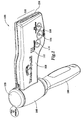
- Display device 100 shown in Figures 1-7, includes a handle 102 having a rotary body 104 disposed on the upper portion thereof.
- Rotary body 104 includes a barrel 106 disposed about a portion of the handle 102, and an extension 108 extending radially from the barrel 106.
- An LED array 110 is disposed on the distal end of the extension 108, opposite the barrel 106.
- a speaker grille 112 is disposed in the extension 108, along with user controls, which may include a message button 114, a sound button 116 and a power button 118.
- Message button 114 may be used to select a message or image for display on the LED array 110 of one or more LEDs 154.
- Sound button 116 may be used to select a sound effect or song to be played by a speaker within the display device 100.
- Power button 118 may be used to turn the display device 100 on or off, and may also be used to select the direction of rotation of the display device 100.
- the upper end of barrel 106 is covered by a cap 120.
- Extension 108 has a back surface 140, a front surface 142, a top surface 144 and a bottom surface 146.
- Barrel 16 has an outer surface 106.
- Surfaces 140-146 are shown as having a warped, non-planar shape in order to evoke the idea of a flag in the wind, but nothing within the present invention is limited to surfaces of this shape.
- surfaces 140-146 could be substantially planar without departing from the spirit and scope of the present invention.
- the outer surface 108 of barrel 106 has a bulging cylindrical shape, but this is not essential to the invention.
- Extension 108 is held together with one or more fasteners 150.
- Fasteners 150 are depicted in display device 100, but nothing in the present invention is limited to this number.
- Cap 120 is retained by one or more upper fasteners 152.
- a single fastener 152 is shown in connection with display device 100, but more fasteners 152 may be employed.
- securement devices other than fasteners 150 and 152 may be employed without departing from the spirit and scope of the present invention. These might include, for example, snaps, clips or adhesives.
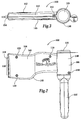
- display device 100 includes a first handle shell 200, a second handle shell 202, a front rotary body shell 204 and a rear rotary body shell 206. Disposed between the front rotary body shell 204 and rear rotary body shell 206, in the extension 108, is a printed circuit board assembly 208.
- a set of battery cells 210 Disposed between the front rotary body shell 204 and rear rotary body shell 206 in the barrel 106, is a set of battery cells 210.
- Battery cells 210 are further disposed between cap 120 and lower contacts retaining disk 212.
- Cap 120 retains a pair of upper battery contacts 214 disposed to contact the upper electrical terminals of battery cells 210.
- lower contacts retaining disk 212 retains a set of lower battery contacts 216-220 disposed to contact the lower electrical terminals of battery cells 210.
- the set of lower battery contacts 216-220 includes first lower contact 216, second lower contact 218 and third lower contact 220.
- upper battery contacts 214, battery cells 210 and lower battery contacts 216-220 represent a complete voltage source, with the voltage of the source being equal to the sum of the voltages of the battery cells 210. This is due to the fact that the battery cells 210 are disposed in a series arrangement. Alternate embodiments may employ a parallel battery circuit or a combination series-parallel battery circuit in order to increase the current capacity available to display device 100.
- Rear shell 206 incorporates a battery compartment 240 inside the barrel 106 and an inner surface 242 inside the extension 108.
- the rear shell 206 can be secured to the other components of display device 100 through fastener bores 244, although alternate embodiments may employ alternate fastening mechanisms.
- an LED aperture 246 is disposed at the distal end of the rear shell 206 opposite the barrel 106.
- an axle bore 248 is disposed at the proximal end of the rear shell 206 inside the barrel and sized for receipt of the axle portion of the handle 102.
- Front shell 204 incorporates a battery compartment 260 inside the barrel 106 and an inner surface 262 inside the extension 108.
- the front shell 204 can be secured to the other components of display device 100 through fastener bores 264, although alternate embodiments may employ alternate fastening mechanisms.
- an LED aperture 266 is disposed at the distal end of the rear shell 206 opposite the barrel 106.
- an axle bore 268 is disposed at the proximal end of the rear shell 206 inside the barrel and sized for receipt of the axle portion of the handle 102.
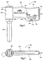
- First handle shell 200 has an inner surface 300 disposed within the grip portion 304 and axle portion 302. Disposed about axle portion 302 is an upper retainer portion 306 and lower retainer portion 308 for axial retention of the rotary body 104 about the axle portion 302 while allowing for free radial motion between the handle 102 and rotary body 104.
- First handle shell 200 includes two fastener bores 310 to facilitate securement of the first handle shell 200 to other components of the display device 100.
- Second handle shell 202 has an inner surface 320 disposed within the grip portion 324 and axle portion 322. Disposed about axle portion 322 is an upper retainer portion 326 and lower retainer portion 328 for axial retention of the rotary body 104 about the axle portion 322 while allowing for free radial motion between the handle 102 and rotary body 104. Second handle shell 202 includes two fastener bores 330 to facilitate securement of the second handle shell 202 to other components of the display device 100, including first handle shell 200.
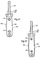
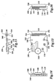
- the printed circuit board assembly 208 is shown in detail in Figures 13-16.
- Printed circuit board assembly 208 includes a printed circuit board 340 having mounting bores 342 disposed therein. Disposed on the printed circuit board 340 is a message button 114, a sound button 116 and a power button 118. The function of these devices is described in detail above. Also disposed on printed circuit board 340 is an integrated circuit 344, a microcontroller 346 and a speaker 348. At one end of the printed circuit board 340 is disposed an LED array 110, including LEDs 154, 350 and 352, disposed on an LED carrier 354. The function of these components is described in detail in connection with Figure 19, below.
- Print circuit board assembly 208 is shown in exploded form in Figure 17.
- printed circuit board 340 incorporates a first thru-hole pattern 380 for receiving message button pins 382 of message button 114, a second thru-hole pattern 392 for receiving sound button pins 396 of sound button 116, and a third thru-hole pattern 394 for receiving power button pins 398 of power button 118.
- the lower battery contact assembly is shown in detail in Figure 18.
- Contact retainer disc 212 retains first lower contact 216, second lower contact 218 and third lower contact 220 via a combination of post bores 384 and retaining posts 386.
- Retaining posts 386 are disposed in the upper surface 388 of the contact retainer disc 212.
- axle bore 390 is also shown.
- a fundamental component of the display device 100 of the present invention is a microcontroller 346 which may be contained in a single package.
- This microcontroller 346 contains flash road-only memory (flash ROM) and random access memory.
- the control program for the microcontroller 346 may be contained in the flash ROM. To minimize the cost of this unit, a relatively simple microcontroller 346 may be used.
- the display device employs a microcontroller, although other units may be employed. Most of the pins of microcontroller 346 are used for input and output signals.
- the microcontroller 346 has four inputs, designated RB1, RB7, RA5 and RB6. Three of the inputs are used for push buttons 114-118, which control various options and functions of the display device 100.
- the forth input is used for an index signal.
- the index signal is generated by a sensor 370, which sends a pulse stream corresponding to the rate of revolution of the display device 100. In one embodiment, the sensor 370 generates one pulse for each revolution of the display device 100. As the display device 100 is spun, the time between index pulses is used to determine the speed at which the unit is spinning. The time between index pulses is determined with respect to the internal clock oscillator of the microcontroller 346.
- the speed of revolution is relatively constant over short intervals, but does vary enough that checking the speed periodically can improve the images displayed.
- the timing of data for the LED array 110 can be set. It is desirable to send information to the LED array 100 at a rate which allows proper geometric proportions for text and graphics displayed thereon as well as to stabilize the position of images in space for each subsequent revolution of the LED array 110.
- the LEDs 154 are arranged in four groups.
- the first group is composed of seven blue LEDs, designated 354 in Figure 18. This group shares a common anode current source PNP transistor 360 which is used to select this group.
- the second group is composed of four red LEDs 350 alternated with three white LEDs 356. This group also has a common anode current source PNP transistor 362.
- the cathodes of the blue LEDs 354 and four red LEDs 350 are tied together through current limiting resistors 364 to outputs of the microcontroller 346.
- the group is enabled by turning on the PNP current source for that group, and then pulling the cathode for that LED low. This provides a current path to turn on the LED.
- LEDs 350 and 354 are usually turned on in an alternate fashion.
- a single white LED 358 is driven by output pin RA1 from the microcontroller 346.
- the microcontroller 346 has independent control of LED 358 because it is connected exclusively to a single output of the microcontroller 346.
- the last group is composed of three Red LEDs and two White LEDs.
- the last group of red LEDs 352 and white LEDs 366 is controlled by a single source PNP transistor 364. All five of LEDs 352 and 366 are turned on or off simultaneously according to the state of PNP transistor 364, which is controlled by microcontroller output RB4. With the LEDs controlled and arranged in the current configuration, the image of an American flag can be generated by turning on all of the blue LEDs 354, red LEDs 352 and 358 and white LEDs 366 for a first period of time, then turning off blue LEDs 354, and turning on red LEDs 350 and white LEDs 356 for a period of time approximately twice as long as the first period of time.
- LEDs 350, 352, 356 and 366 are arranged in a single line of alternating red and white LEDs. This allows a sharp edge of the stripes of the flag. Text and/or graphics can also be created by varying the state of LEDs 350 and 356 as the display device 100 rotates. LEDs 358 can also be used to increase the height of the image. Because LEDs 350, 352, 356 and 366 are arranged as alternating red and white LEDs, the image will be composed of alternating red and white bands of dots. Because blue LEDs 354 are independently controlled in the same manner as LEDs 350 and 356, text and/or graphics can be created with blue LEDs 354 as well.
- the height of the blue image can also be increased by controlling white LED 358, but due to the fact that white LED 358 is physically offset from blue LEDs 354, the timing of the white LED 358 must either precede or follow the timing of blue LEDs 354 depending upon the direction of revolution of display device 100 in order to align the white image with the blue image.
- Other bursts of color such as fireworks can be generated due to the independent control of the various LEDs. These bursts of color or graphics can also be used to create animated graphics such as exploding fireworks.
- the microcontroller 364 When the display device 100 is turned off, the microcontroller 364 is placed in a sleep mode with all of the LEDs and bank transistors turned off. The pulse frequency generator within microcontroller 364 is also stopped. In this mode, the microcontroller 364 draws very little power, such that the life of battery cells 210 in this mode approaches the shelf life of the battery cells 210. When the power button 118 is pressed, the microcontroller 364 detects this change, and is woken up to become active. Various tunes and graphics are stored along with control code in the microcontroller 364. For embodiments of the present invention using flash memory, the display device 100 may be easily reprogrammed with new text, graphics and control code.
- the LEDs could all be independently controlled using a microcontroller with more outputs.
- the LEDs could be arranged in three groups of color. If one group is Red, the second is Green, and the third is Blue, then by controlling the LEDs either singly or in combination with the other primary colors, any color including White can be generated.
- a further extension of this idea would allow the intensity of the LEDs to be varied. This would allow various shades of color including gray to be generated. With increased numbers of LEDs, higher resolution displays can be created, and thus finer detailed graphics and texts.
- At least one of the microcontroller outputs is driven by a pulse generator in the microcontroller 346.
- the frequency of the pulse generated thereby may be reduced in a second integrated circuit 344.
- the second integrated circuit 344 divides the frequency of the pulse by a factor of eight.
- the square-wave output from this second integrated circuit 344 can be used to drive one or more audio transducers, such as speaker 348, to generate sound effects and/or music.
- speaker 348 is a piezoelectric device, and responds to voltage changes across a piezoelectric crystal to produce vibrations, thereby generating audible sounds in the surrounding air. If the voltage across a piezoelectric crystal is kept constant, the piezoelectric crystal does not consume power. There is, therefore, no need to determine the logic state of the output of the second integrated circuit 344 driving speaker 348 when no audio signal is desired. If a different type of audio transducer were used for speaker 348, a capacitor would normally be required to achieve the same level of performance at a similar level of power consumption.
- a true square wave is composed of an infinite series of component signals, including many component signals at the upper end of the 20 kHz human hearing range. Sounds in this range can be unpleasant to the human ear.
- a resistor 380 is placed in series with the speaker 348, which, owing to the inherent capacitance of the piezoelectric transducer, acts as an R-C filter to filter out many of the higher harmonics from the square-wave driving the speaker 348, thus providing a more pleasing tone by "rounding off" the corners of the square wave generated by the digital electronics.
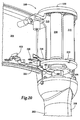
- Figure 20 depicts a mechanism that may be used for determining the rotational speed of the display device 100 according to one embodiment of the present invention.
- first handle shell 200 and second handle shell 202 form an axial cam disc 406 disposed beneath lower battery contact retainer disc 212 retaining lower battery contact 218 and lower battery contact 220 at the lower end of battery cells 210.
- An axial cam lobe 400 is disposed on the lower face of axial cam disc 406 approximately in the center of second handle shell 202.
- Spring contact 222 fixed in place within rotary body front shell 204 by a set of protruding retaining features 408, has a follower 402 formed into its distal end.
- Follower 402 rides on the lower surface of axial cam disc 406 as the rotary body 104 revolves about the handle 102. In the position shown in Figure 20, follower 402 is shown riding on the flat lower surface of the axial cam disc 406. In this position, switch contact 404 rests against, and makes an electrical contact with, the lower surface of lower battery contact 220.
- follower 402 encounters axial cam lobe 400.
- follower 402 moves downward, away from the flat lower surface of the axial cam disc 406.
- switch contact 404 moves downward along with it, away from physical and electrical contact with lower battery contact 220. Accordingly, once per revolution, the switch contact 404 breaks electrical contact with lower battery contact 220.
- follower 402 moves upward back into contact with the flat lower surface of axial cam disc 406, thereby bringing switch contact 404 back into physical and electrical contact with lower battery contact 220.
Landscapes
- Engineering & Computer Science (AREA)
- Physics & Mathematics (AREA)
- General Physics & Mathematics (AREA)
- Theoretical Computer Science (AREA)
- Computer Hardware Design (AREA)
- Devices For Indicating Variable Information By Combining Individual Elements (AREA)
- Illuminated Signs And Luminous Advertising (AREA)
Applications Claiming Priority (2)
| Application Number | Priority Date | Filing Date | Title |
|---|---|---|---|
| US10/717,180 US7236146B2 (en) | 2003-02-12 | 2003-11-19 | Hand-held display device |
| US717180 | 2003-11-19 |
Publications (2)
| Publication Number | Publication Date |
|---|---|
| EP1533780A2 true EP1533780A2 (de) | 2005-05-25 |
| EP1533780A3 EP1533780A3 (de) | 2006-10-25 |
Family
ID=34435750
Family Applications (1)
| Application Number | Title | Priority Date | Filing Date |
|---|---|---|---|
| EP04254153A Withdrawn EP1533780A3 (de) | 2003-11-19 | 2004-07-12 | Handanzeigeeinrichtung mit Anzeigeelement auf einem drehbaren Körper |
Country Status (4)
| Country | Link |
|---|---|
| US (1) | US7236146B2 (de) |
| EP (1) | EP1533780A3 (de) |
| CN (1) | CN1619609A (de) |
| TW (1) | TW200518012A (de) |
Families Citing this family (19)
| Publication number | Priority date | Publication date | Assignee | Title |
|---|---|---|---|---|
| USD508540S1 (en) * | 2003-02-12 | 2005-08-16 | Axxion Group Corporation | Hand-held display device |
| US20050237272A1 (en) * | 2004-03-26 | 2005-10-27 | Jessica Josephson | Display device |
| USD508959S1 (en) * | 2004-08-12 | 2005-08-30 | Ralph A. Marchitto | Set of mailbox flag decals |
| USD564595S1 (en) * | 2006-08-11 | 2008-03-18 | Barrett W Raymond | Vehicle sign having base and flag |
| DE602007004241D1 (de) * | 2006-08-31 | 2010-02-25 | Cardlab A P S | Karte zum präsentieren von informationen während des winkens |
| US8262473B2 (en) * | 2008-01-04 | 2012-09-11 | Mattel, Inc. | Interactive toy with visual and audio feedback |
| US20100171681A1 (en) * | 2009-01-05 | 2010-07-08 | Manuel Cabanas | Method and apparatus for displaying digital data |
| CN101782189A (zh) * | 2009-01-16 | 2010-07-21 | 富士迈半导体精密工业(上海)有限公司 | 照明装置 |
| US8866703B2 (en) | 2012-03-01 | 2014-10-21 | Crayola Llc | Persistence-of-vision display with stylus input device |
| WO2014185965A1 (en) * | 2013-05-14 | 2014-11-20 | A Hot Flag Llc | Flag |
| EP3035230A1 (de) | 2014-12-19 | 2016-06-22 | Cardlab ApS | Verfahren und Anordnung zum Erzeugen eines Magnetfeldes |
| MA41187A (fr) | 2014-12-19 | 2021-04-07 | Cardlab Aps | Procédé et ensemble pour générer un champ magnétique et procédé de fabrication d'un ensemble |
| EP3082071A1 (de) | 2015-04-17 | 2016-10-19 | Cardlab ApS | Vorrichtung und verfahren zur ausgabe eines magnetfelds |
| KR101681912B1 (ko) | 2016-02-05 | 2016-12-02 | (주)거노코퍼레이션 | 광원의 시각적 잔상을 이용하여 영상을 표시하는 웨어러블 전자 장치 |
| US9984605B2 (en) * | 2016-10-27 | 2018-05-29 | Sherry Berjeron | Wearable display |
| USD860321S1 (en) * | 2017-03-21 | 2019-09-17 | Lg Electronics Inc. | Digital sign |
| US10697621B1 (en) * | 2019-12-18 | 2020-06-30 | Lizal, Inc. | Illuminated flag |
| US10871278B1 (en) | 2019-12-18 | 2020-12-22 | Lizal, Inc. | Illuminated flag |
| KR102562079B1 (ko) * | 2021-06-15 | 2023-08-02 | (주)거노코퍼레이션 | 회전식 엘이디 디스플레이 장치 |
Family Cites Families (19)
| Publication number | Priority date | Publication date | Assignee | Title |
|---|---|---|---|---|
| US4601255A (en) | 1984-08-27 | 1986-07-22 | Ettore Marcotti | Flagpole device |
| US4807557A (en) | 1987-09-14 | 1989-02-28 | Lodisio Richard A | Safety alert for water skiers |
| GB8908322D0 (en) | 1989-04-13 | 1989-06-01 | Stellar Communicat Ltd | Display |
| ATE154718T1 (de) | 1991-12-12 | 1997-07-15 | Avix Inc | Anzeige-stock mit einer anordnung lichtemittierender zellen |
| JP3526634B2 (ja) | 1994-09-26 | 2004-05-17 | アビックス株式会社 | 画像読み取り機能を備えたスキャン式表示装置 |
| US5548300A (en) * | 1994-12-20 | 1996-08-20 | Avix Inc. | Manual rotation type display device |
| US5748157A (en) | 1994-12-27 | 1998-05-05 | Eason; Richard O. | Display apparatus utilizing persistence of vision |
| US6239774B1 (en) | 1995-10-31 | 2001-05-29 | Mitchell A. Altman | Persistent image maker |
| GB9621061D0 (en) * | 1996-10-09 | 1996-11-27 | Frontline Display Limited | Image display apparatus |
| US6278419B1 (en) | 1997-06-26 | 2001-08-21 | Light Spin Ltd. | Moving display |
| DE19737621C1 (de) * | 1997-08-28 | 1999-03-04 | Zellner Datentechnik Gmbh | Displayanordnung zur Darstellung von Informationen |
| US6193384B1 (en) | 1998-03-18 | 2001-02-27 | Buckminster G. Stein | Ceiling fan sign |
| US6037876A (en) | 1998-04-23 | 2000-03-14 | Limelite Industries, Inc. | Lighted message fan |
| GB9901545D0 (en) * | 1999-01-26 | 1999-03-17 | G12 Ltd | Display aparatus |
| USD433022S (en) | 1999-02-09 | 2000-10-31 | G12 Ltd | Display apparatus |
| US6222459B1 (en) | 1999-07-22 | 2001-04-24 | Opcom, Inc. | Method of word screen formation by laser light projection and the structure for the same |
| US6265984B1 (en) * | 1999-08-09 | 2001-07-24 | Carl Joseph Molinaroli | Light emitting diode display device |
| USD442597S1 (en) | 1999-11-29 | 2001-05-22 | Versatile Visions, Llc | Virtual image writer device |
| US6626293B2 (en) | 2001-02-14 | 2003-09-30 | Wallace E. St. Jeor | Golf club reminder device |
-
2003
- 2003-11-19 US US10/717,180 patent/US7236146B2/en not_active Expired - Fee Related
-
2004
- 2004-06-29 TW TW093119220A patent/TW200518012A/zh unknown
- 2004-07-12 EP EP04254153A patent/EP1533780A3/de not_active Withdrawn
- 2004-09-20 CN CN200410078066.9A patent/CN1619609A/zh active Pending
Also Published As
| Publication number | Publication date |
|---|---|
| US7236146B2 (en) | 2007-06-26 |
| EP1533780A3 (de) | 2006-10-25 |
| CN1619609A (zh) | 2005-05-25 |
| TW200518012A (en) | 2005-06-01 |
| US20040155845A1 (en) | 2004-08-12 |
Similar Documents
| Publication | Publication Date | Title |
|---|---|---|
| US7236146B2 (en) | Hand-held display device | |
| US10732745B2 (en) | Light emitting diode switch device and array | |
| US20070097681A1 (en) | Lighting device | |
| US20050087702A1 (en) | Multi-mode electromagnetic radiation emitting device | |
| KR20050056207A (ko) | 회전하는 가시 표면상의 정보 시각화 장치 | |
| EP1780053A1 (de) | Lichtemittierende Vorrichtung für eine Reifenseitenwand und Reifen mit einer solchen Vorrichtung | |
| US7165857B2 (en) | Interactive LED display device | |
| US11540367B2 (en) | Electrical light set circuit, light strip and control apparatus therefor | |
| KR101741032B1 (ko) | 원통형 엘이디 전광판 | |
| JP2001236801A (ja) | 回転表示灯 | |
| JP3182500U (ja) | レコードプレーヤ用スタビライザー | |
| US20050237272A1 (en) | Display device | |
| EP2101882A1 (de) | Springseilvorrichtung | |
| JP3602999B2 (ja) | 振り子装置 | |
| CN119878558A (zh) | 发光标志风扇 | |
| JPH06308903A (ja) | 回転発光表示装置 | |
| JP2000221058A (ja) | 車両用メータ | |
| JP2002267506A (ja) | 計器照明装置 | |
| JP2005010713A (ja) | ディスプレイ装置及びそのディスプレイ装置を備えたテーブル | |
| HK1232008B (zh) | 发光二极管开关装置及阵列 | |
| HK1195660B (en) | Light emitting diode switch device and array | |
| HK1195660A (en) | Light emitting diode switch device and array |
Legal Events
| Date | Code | Title | Description |
|---|---|---|---|
| PUAI | Public reference made under article 153(3) epc to a published international application that has entered the european phase |
Free format text: ORIGINAL CODE: 0009012 |
|
| AK | Designated contracting states |
Kind code of ref document: A2 Designated state(s): AT BE BG CH CY CZ DE DK EE ES FI FR GB GR HU IE IT LI LU MC NL PL PT RO SE SI SK TR |
|
| AX | Request for extension of the european patent |
Extension state: AL HR LT LV MK |
|
| PUAL | Search report despatched |
Free format text: ORIGINAL CODE: 0009013 |
|
| AK | Designated contracting states |
Kind code of ref document: A3 Designated state(s): AT BE BG CH CY CZ DE DK EE ES FI FR GB GR HU IE IT LI LU MC NL PL PT RO SE SI SK TR |
|
| AX | Request for extension of the european patent |
Extension state: AL HR LT LV MK |
|
| STAA | Information on the status of an ep patent application or granted ep patent |
Free format text: STATUS: THE APPLICATION IS DEEMED TO BE WITHDRAWN |
|
| AKX | Designation fees paid | ||
| 18D | Application deemed to be withdrawn |
Effective date: 20070201 |
|
| REG | Reference to a national code |
Ref country code: DE Ref legal event code: 8566 |