EP1533675A1 - Verfahren und Vorrichtung zur Erwärmung des Steuergases für einen pneumatischen Regler eines Gas-Druckregelgerätes - Google Patents
Verfahren und Vorrichtung zur Erwärmung des Steuergases für einen pneumatischen Regler eines Gas-Druckregelgerätes Download PDFInfo
- Publication number
- EP1533675A1 EP1533675A1 EP04027393A EP04027393A EP1533675A1 EP 1533675 A1 EP1533675 A1 EP 1533675A1 EP 04027393 A EP04027393 A EP 04027393A EP 04027393 A EP04027393 A EP 04027393A EP 1533675 A1 EP1533675 A1 EP 1533675A1
- Authority
- EP
- European Patent Office
- Prior art keywords
- gas
- pressure
- inlet
- regulator
- vortex chamber
- Prior art date
- Legal status (The legal status is an assumption and is not a legal conclusion. Google has not performed a legal analysis and makes no representation as to the accuracy of the status listed.)
- Granted
Links
- 238000010438 heat treatment Methods 0.000 title claims abstract description 18
- 238000000034 method Methods 0.000 title claims abstract description 10
- 230000000694 effects Effects 0.000 claims abstract description 8
- 238000005259 measurement Methods 0.000 claims description 2
- 230000008569 process Effects 0.000 claims description 2
- 230000001105 regulatory effect Effects 0.000 abstract 1
- 239000007789 gas Substances 0.000 description 117
- VNWKTOKETHGBQD-UHFFFAOYSA-N methane Chemical compound C VNWKTOKETHGBQD-UHFFFAOYSA-N 0.000 description 8
- 238000011144 upstream manufacturing Methods 0.000 description 8
- 239000013078 crystal Substances 0.000 description 4
- 230000001174 ascending effect Effects 0.000 description 3
- 230000015572 biosynthetic process Effects 0.000 description 2
- 230000008859 change Effects 0.000 description 2
- 238000001816 cooling Methods 0.000 description 2
- 230000009467 reduction Effects 0.000 description 2
- 230000008901 benefit Effects 0.000 description 1
- 239000003638 chemical reducing agent Substances 0.000 description 1
- 230000002596 correlated effect Effects 0.000 description 1
- 230000000875 corresponding effect Effects 0.000 description 1
- 230000008878 coupling Effects 0.000 description 1
- 238000010168 coupling process Methods 0.000 description 1
- 238000005859 coupling reaction Methods 0.000 description 1
- 230000017525 heat dissipation Effects 0.000 description 1
- 150000004677 hydrates Chemical class 0.000 description 1
- 238000009413 insulation Methods 0.000 description 1
- 239000012528 membrane Substances 0.000 description 1
- 210000000056 organ Anatomy 0.000 description 1
- 230000000630 rising effect Effects 0.000 description 1
- 238000000926 separation method Methods 0.000 description 1
Images



Classifications
-
- F—MECHANICAL ENGINEERING; LIGHTING; HEATING; WEAPONS; BLASTING
- F24—HEATING; RANGES; VENTILATING
- F24V—COLLECTION, PRODUCTION OR USE OF HEAT NOT OTHERWISE PROVIDED FOR
- F24V99/00—Subject matter not provided for in other main groups of this subclass
-
- F—MECHANICAL ENGINEERING; LIGHTING; HEATING; WEAPONS; BLASTING
- F25—REFRIGERATION OR COOLING; COMBINED HEATING AND REFRIGERATION SYSTEMS; HEAT PUMP SYSTEMS; MANUFACTURE OR STORAGE OF ICE; LIQUEFACTION SOLIDIFICATION OF GASES
- F25B—REFRIGERATION MACHINES, PLANTS OR SYSTEMS; COMBINED HEATING AND REFRIGERATION SYSTEMS; HEAT PUMP SYSTEMS
- F25B9/00—Compression machines, plants or systems, in which the refrigerant is air or other gas of low boiling point
- F25B9/02—Compression machines, plants or systems, in which the refrigerant is air or other gas of low boiling point using Joule-Thompson effect; using vortex effect
- F25B9/04—Compression machines, plants or systems, in which the refrigerant is air or other gas of low boiling point using Joule-Thompson effect; using vortex effect using vortex effect
Definitions
- the invention relates to a method for heating the control gas for a pneumatic regulator of a gas pressure regulator and a Device for heating the control gas in the inlet pressure line to a pneumatic regulator of a gas pressure regulator, in particular to carry out the aforementioned method.
- gas pressure regulators are used in gas pressure control systems, which work with auxiliary power, which is a pneumatic regulator assigned.
- the controller is correlated to the main actuator Gas relaxation and thus the corresponding temperature reduction.
- the risk of icing then exists when due to the relaxation of a gas due to the Joule-Thomsen effect the temperature of the gas drops sharply. It is true that with a pressure reduction of 1 bar a decrease in temperature by approx. 0.4 ° K is connected.
- the dew point of the gas can become methane crystals form, which disturb the function in particular of the controller. It exists but not only the danger of the aforementioned blockage of the Nozzle or the flow channels in the controller, but rather causes a strong Cooling of the gas, and thus of the components, also a negative impact on the elasticity behavior of the comparator membranes. This is synonymous with unwanted major deviations.
- the invention is therefore based on the object, a method and a To provide device of the type mentioned, with the Preheating the gas flow to the controller out in a cheaper way can be accomplished.
- the object is achieved according to the method thereby solved that after the Ranque-Hilsch effect in a cylindrical Vortex chamber tangentially inflowing gas in particular with supercritical pressure gradient is different in two gas streams Temperature divides, wherein the warmer of the two gas streams through a Heat exchanger heated the control gas for the pneumatic controller.
- supercritical means that the absolute Gas pressure before entering the vortex chamber is about twice as high as the absolute pressure behind the vortex chamber.
- the device for heating the control gas in the inlet pressure line to the pneumatic regulator of a gas pressure regulator in particular for carrying out the method according to the invention is characterized through a housing with a cylindrical vortex chamber with a Inlet for the tangential inflow of the inlet pressure gas with a Pressure drop off, and at least one outlet for the warm and at least one further outlet for the cold gas, and a the Vortex chamber surrounding forming a gap space Heat exchanger, wherein the gap space at least one input port and at least one output port for the control gas for the having pneumatic regulator.
- the pressure gradient is supercritical.
- the so-called Ranque effect arises in a vortex tube or in a Hilsch tube.
- the inlet for tangential inflow of the gas in the head area, ie at the upper end of the cylindrical Whirl chamber is arranged, wherein the warm gas outlet in the foot area, that is, at the opposite end to the inlet of the Input pressure gas is provided in the vortex chamber.
- the cold gas outlet in the front of the cylindrical vortex chamber located at the opposite end too the warm gas outlet is arranged.
- the cold gas outlet centric in the face of the cylindrical Swirl chamber is located around the center in the vortex chamber ascending Cold gas can flow out.
- the hot gas outlet is through a throttle changeable in its cross section, wherein a correlation between the introduced gas volume and that through the cold gas outlet and the hot gas outlet emitted volume flow. Accordingly, the inlet for the input pressure gas in the Eddy chamber variable.
- this throttle has a center with the tip in the Vortex chamber projecting cone, the cone not only the Change of the cross section serves, but beyond that Distribution of the gas flow into the cold and hot gas flows influenced.
- the aperture on the cold gas side is variable to different in to be able to process the vortex chamber inflowing gas quantities.
- the gap space has at least one Inlet opening and at least one outlet opening for the control gas for the pneumatic regulator. It is essential that the entrance and the Output opening for the control gas in each case to the opposite Ends of the cylindrical vortex chamber are arranged to make one possible sweep the large area of the heat exchanger through the heated gas to let and to the temperature gradient in the vortex chamber optimal exploit because the temperature of the gas in the range of gasauslasses is highest.
- the invention is also the control of the supply of heated control gas to the controller.
- a valve to the inlet in the vortex chamber especially in the line arranged a valve to the inlet in the vortex chamber. Is advantageous if through the valve the inlet for the inlet pressure gas in the Vortex chamber is opened before the pneumatic regulator control gas requests. That is, the device for heating the control gas gets a certain flow to the regulator from the beginning with hot gas to supply.
- shut-off valve in the line to the Inlet into the vortex chamber a shut-off valve is arranged.
- This Shut-off valve is operated manually, that is, whenever the Regulator is activated, the shut-off valve is opened.
- a switching valve is at Beginning change of the setting pressure of the pneumatic regulator driven.
- the switching valve is designed so that it through the signal pressure is opened before the gas pressure regulator by the pneumatic regulator is put into operation.
- This has the advantage that the device for heating the control gas automatically with their Activity begins, and that setpoint changes to the pneumatic Regulator no readjustment of the setpoint upstream Control valve, as is the case with variant two, so that the closing pressure of the plant exclusively from the pneumatic Controller is determined.
- the housing is in two parts with a Housing head and a housing sump is formed, wherein housing head and housing body are thermally separated to allow cooling of the Hull through the head, which has the Kaltgasabströmtechnisch to prevent. It turns out that when the hull is frozen the function of the device is not guaranteed.
- the housing sump has an axially extending second gap space on, which is arranged approximately semicircular in the housing base. At the the lower end is connected to the warm gas outlet, at the upper end It ends in a line that leads to the cold gas line.
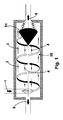
- Figure 1 shows the basic principle of a vortex tube or Hilsch tube called;
- the tangential inflow of the gas is characterized can be seen by the arrow 1 in the cylindrical vortex chamber 30, wherein the tangentially flowing gas stream into an outer gas stream, characterized by the arrows 3, and an inner ascending Gas flow, characterized by the arrows 4, divides.
- the ascending inner cold gas flow, characterized by the arrows 4, is out of the Vortex tube 2, led out according to the arrow 5, whereas the Warmgasanteil led out of the vortex tube according to the arrow 6 becomes.
- the cone designated 51 promotes the division of the imported tangential gas flow in the cold gas and the warm gas stream.
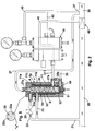
- FIGS 2 to 4 show both the Device 10 for heating the control gas, as well as the pneumatic regulator 15 and the actuator 40 as part of the gas pressure control system.
- FIG. 2 The circuits shown in Figures 2 to 4 differ in the Essentially only by the arrangement of a shut-off valve in the Input pressure line (Fig. 2), a control valve (Fig. 3) or a Switching valve in the inlet pressure line (Fig. 4).
- the check valve 25 In the input pressure line 22 is the check valve 25, by means of which the volume the gas flow into the cylindrical vortex chamber 30 of the housing 11th is controlled.
- the into the cylindrical vortex chamber 30 through the input pressure line 22 tangential inflowing gas stream divides accordingly the description of FIG. 1 in a centrally rising cold gas stream 4 and a concentrically discharged hot gas stream 5.
- the cold gas stream 4 is through the cold gas outlet 27 a and 27 Kaltgasabströmtechnisch the Main line 20 fed behind the actuator 40.
- the throttle 50 includes an adjustable cone 51, in collaboration with the cylindrical shell 32 of the vortex chamber 30 forms a gap 52 through the concentrically guided hot gas through the outlet 35a through the Warmgasabströmtechnisch 35 turn the main line 20 after the Actuator 40 is supplied.
- the vortex chamber 30 is formed radially by the cylindrical shell 32; this cylindrical jacket 32 in conjunction with the gap 33 is part of the heat exchanger 34.
- the inlet opening 23a through the Steuergaszuströmtechnisch 23 Through the inlet opening 23a through the Steuergaszuströmtechnisch 23, the supply of the control gas in the Gap space 33.
- the wall 32 of the heat exchanger 34 is replaced by the Warm gas stream 5 is heated.
- the through the conduit 23 into the gap 33rd inflowing control gas is in the gap 33 by the hot gas flow 5 in the vortex chamber is heated and is finally through the output port 37a supplied to the controller 15 through the control gas discharge line 37.
- the regulator 15 finds a splitting of the through the control gas discharge 37th supplied heated control gas inasmuch as a part of the Gas flow through the control pressure line 41 is supplied to the actuator 40, wherein the remaining part of the control gas 15 supplied to the control by the Outflow line 42 of the main line 20 behind the actuator 40 is supplied becomes.
- the regulator 15 itself is through a measuring line 43 to the main line 20 connected behind the actuator 40.
- the operation of the device for heating the control gas is now such that the start-up of the regulator, the shut-off valve 25 is opened, with the result that the controller 15 is supplied with warm control gas, so at work of the actuator and thus a gas relaxation formation of To prevent methane crystals in the controller 15.
- the hot gas line 35 is guided as a double tube around the Kaltgasabströmtechnisch to heat the Kaltgasabströmtechnisch from the outside.
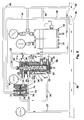
- FIG. 3 differs essentially from the 2 only by the connection of a control valve 60 in the Input pressure line 22.
- the same Objects also carry the same reference numerals.
- the upstream of the device 10 for heating the control gas Control valve 60 is set to a set point that is slightly higher than the setpoint of the pneumatic regulator 15. As soon as the outlet pressure on the setpoint of this control valve 60 has dropped, it opens in it integrated valve 67 and takes the device 10 in operation. If now the Output pressure drops further and the pneumatic controller 15 in function takes, this is supplied with the through the line 37 to the controller supplied heated control gas.
- the upstream control valve 60 is now fully open; the pending before the pressure reducer 60 in the line 21 Input pressure is fully in the cylindrical vortex chamber 30th directed. In complete decommissioning of the pressure control system is running System to a closing pressure from the upstream control valve 60th is determined.
- FIG. 4 differs from that of FIG according to Fig. 2 or 3 in that the device 10 for heating the Control gas, the switching valve 70 is connected upstream. Also in terms of the Representation of FIG. 4 holds that the same objects same Reference numerals as in FIGS. 2 and 3 have.
- the device 10 is preceded by the switching valve 70.
- This switching valve 70 is characterized by a beginning Stelldruck basicung the pneumatic regulator 15 by the pressure in the control pressure line 41st driven.
- the drive 71 of the switching valve 70 is on the closing side 72nd from the outlet pressure in the main line 20 behind the actuator 40 and from the force of the closing spring 73 acted upon.
- the opening side 74 of Drive 71 of the switching valve 70 is connected by the control pressure line 41 the pneumatic regulator 15 in connection. Is the gas pressure regulator out of service, the pressure in the control pressure line 41 is equal to the Outlet pressure, d. H. the pressure in the main line 20 behind the actuator 40.
- the actuator 76 in the switching valve 70 is by the force of the closing spring 73 closed.
- the starting pressure build-up opens the actuator 76 in Switching valve 70 and takes the device for heating the control gas in function.
- the switching valve 70 is designed so that it by the Signal pressure is opened before the actual gas pressure regulator over the pneumatic regulator 15 is put into operation.
- the expanded gas is a Achieve temperature resulting from the Joule-Thomsen effect.
- the Measurement of the output pressure for the pneumatic controller 15 takes place via the line 43. Consequently, at the measuring point 27 no icing enter, is the controller 15 through the line 42 outflowing control gas discharged through this measuring line 43.
- FIGS. 6 and 7 show an embodiment according to FIG. 2, in which the exiting from the outlet 35a hot gas still to heat the Housing body 11 b is used. That is, the according to Figure 2 in Foot area arranged hot gas line 35 is located at the Embodiment according to Figures 6 and 7 immediately below Housing head 11a as a hot gas line 35b.
- To warm up the Housing body as a connection between outlet 35a and the Hot gas line 35b is an axially extending second gap space 12th provided, which extends over part of the lateral surface of the housing body 11b extends. That is, the gap is roughly semicircular, so that the largest possible surface for heat dissipation exists (FIG 7). It has been found that this also the icing of the Housing 11, and in particular of the housing sump 11 b, avoided can be.
- this is achieved by switching valve 70 the line 21 supplied gas in the housing of the vortex chamber 30th heated.
Landscapes
- Engineering & Computer Science (AREA)
- Physics & Mathematics (AREA)
- Thermal Sciences (AREA)
- Mechanical Engineering (AREA)
- General Engineering & Computer Science (AREA)
- Chemical & Material Sciences (AREA)
- Combustion & Propulsion (AREA)
- Filling Or Discharging Of Gas Storage Vessels (AREA)
- Fluid-Driven Valves (AREA)
- Details Of Valves (AREA)
- Control Of Fluid Pressure (AREA)
Abstract
Description
- Fig. 1
- veranschaulicht das Grundprinzip eines Wirbelrohres bzw. einer Wirbelkammer;
- Fig. 2
- zeigt die Vorrichtung zur Erwärmung des Gases in der Kopplung mit einem pneumatischen Regler und einem der Vorrichtung vorgeschalteten Absperrventil,
- Fig. 3
- zeigt eine Vorrichtung gemäß Fig. 1, wobei der Vorrichtung selbst ein pneumatisches Steuerventil vorgeschaltet ist;
- Fig. 4
- zeigt die Vorrichtung gemäß Fig. 2 mit einem der Vorrichtung vorgeschalteten Schaltventil.;
- Fig. 5
- zeigt die Einzelheit "X" aus Fig. 2 in einer Draufsicht;
- Fig. 6
- zeigt eine Vorrichtung entsprechend Fig. 2, bei der das Gehäuse einen zweiten Spaltraum aufweist;
- Fig. 7
- zeigt einen Schnitt gemäß der Linie VII - VII aus Fig. 6;
- Fig. 8
- zeigt eine Vorrichtung entsprechend Fig. 4, bei der das Gas mit dem Eingangsdruck für das Schaltventil durch das Gehäuse vorgewärmt wird.
Um eine Vereisung auch in der Kaltgasabströmleitung 27 zu verhindern, ist nach einem Merkmal der Erfindung die Warmgasleitung 35 als doppeltes Rohr um die Kaltgasabströmleitung geführt, um die Kaltgasabströmleitung von außen zu erwärmen.
Claims (25)
- Verfahren zur Erwärmung des Steuergases für einen pneumatischen Regler (15) eines Gas-Druckregelgerätes, wobei nach dem Ranque-Effekt ein in einer zylindrischen Wirbelkammer (30) tangential einströmendes Gas mit Druckgefälle sich in zwei Gasströme (4, 5) unterschiedlicher Temperatur aufteilt, wobei der wärmere (5) der beiden Gasströme durch einen Wärmetauscher (34) das Steuergas für den pneumatischen Regler (15) erwärmt.
- Vorrichtung (10) zur Erwärmung des Steuergases in der Eingangsdruckleitung zu einem pneumatischen Regler (15) eines Gas-Druckregelgerätes, insbesondere nach Anspruch 1, umfassend ein Gehäuse (11) mit einer zylindrischen Wirbelkammer (30) mit einem Einlass (22a) zum tangentialen Einströmen des Eingangsdruckgases mit einem überkritischen Druckgefälle und mindestens einem Auslass (35a) für das Warm- und mindestens einem weiteren Auslass (27a) für das Kaltgas, sowie einem die Wirbelkammer (30) unter Bildung eines Spaltraumes (33) umgebenden Wärmetauschers (34), wobei der Spaltraum (33) mindestens eine Eingangsöffnung (22a) und mindestens eine Ausgangsöffnung (37a) für das Steuergas für den pneumatischen Regler (15) aufweist.
- Vorrichtung nach Anspruch 2,
dadurch gekennzeichnet, dass der Einlass (22a) zum tangentialen Einströmen des Gases im Kopfbereich der zylindrischen Wirbelkammer (33) angeordnet ist. - Vorrichtung nach Anspruch 2,
dadurch gekennzeichnet, dass der Warmgasauslass (35a) im Fußbereich, das heißt am entgegengesetzten Ende zu dem Einlass des Eingangsdruckgases in der Wirbelkammer (33) vorgesehen ist. - Vorrichtung nach Anspruch 4,
dadurch gekennzeichnet, dass der Kaltgasauslass (27a) in der Stirnseite der zylindrischen Wirbelkammer (30) angeordnet ist, die sich am entgegengesetzten Ende zu dem Warmgasauslass (35a) befindet. - Vorrichtung nach Anspruch 5,
dadurch gekennzeichnet, dass der Kaltgasauslass (27a) zentrisch in der Stirnseite der zylindrischen Wirbelkammer (30) angeordnet ist. - Vorrichtung nach Anspruch 2,
dadurch gekennzeichnet, dass die Ein- und die Ausgangsöffnung (23a, 37a) für das Steuergas jeweils an dem entgegengesetzten Ende der zylindrischen Wirbelkammer (30) angeordnet sind. - Vorrichtung nach Anspruch 2,
dadurch gekennzeichnet, dass der Warmgasauslass (35a) durch eine Drossel (50) in seinem Querschnitt veränderlich ist. - Vorrichtung nach Anspruch 2,
dadurch gekennzeichnet, dass der Einlass (22a) für das Eingangsdruckgas in seinem Querschnitt veränderlich ist. - Vorrichtung nach Anspruch 8,
dadurch gekennzeichnet, dass die Drossel (50) einen in die Wirbelkammer (30) ragenden Konus (51) aufweist. - Vorrichtung nach Anspruch 2,
dadurch gekennzeichnet, dass in der Eingangsdruckleitung (22) zu dem Einlass (22a) in die Wirbelkammer (33) ein Ventil (25, 60, 70) angeordnet ist. - Vorrichtung nach Anspruch 11,
dadurch gekennzeichnet, dass durch das Ventil (25, 60, 70) der Einlass für das Eingangsdruckgas in die Wirbelkammer (33) geöffnet wird, bevor der pneumatische Regler (15) Steuergas anfordert. - Vorrichtung nach Anspruch 11 oder 12,
dadurch gekennzeichnet, dass in der Leitung (22) zu dem Einlass (22a) in die Wirbelkammer (33) ein Absperrventil (25) angeordnet ist. - Vorrichtung nach Anspruch 11 oder 12,
dadurch gekennzeichnet, dass in der Leitung (22) zu dem Einlass (22a) in die Wirbelkammer (33) ein pneumatisches Steuerventil (60) vorgesehen ist. - Vorrichtung nach Anspruch 14,
dadurch gekennzeichnet, dass der Solldruck zum Öffnen des Steuerventils (60) höher ist, als der Solldruck des pneumatischen Reglers (15). - Vorrichtung nach Anspruch 11 oder 12,
dadurch gekennzeichnet, dass in der Leitung (22) zu dem Einlass (22a) in die Wirbelkammer (33) ein Schaltventil (70) vorgesehen ist. - Vorrichtung nach Anspruch 16,
dadurch gekennzeichnet, dass das Schaltventil (70) so ausgelegt ist, dass es durch den Stelldruck geöffnet wird, bevor der pneumatische Regler (15) das Gas-Druckregelgerät in Betrieb nimmt. - Vorrichtung nach Anspruch 2,
dadurch gekennzeichnet, dass von dem Regler (15) durch einen Abströmleitung (42) das Steuergas in die Hauptleitung (20) hinter dem Stellgerät (40) eingeführt wird, wobei die Messung des Ausgangsdruckes hinter dem Stellgerät (40) an einem Messpunkt (27) der Abströmleitung (42) in der Hauptleitung (20) erfolgt, um am Messpunkt (27) keine funktionsstörende Vereisung eintreten zu lassen. - Vorrichtung nach Anspruch 2,
dadurch gekennzeichnet, dass die Kaltgasabströmleitung (27) von der Warmgasabströmleitung (35) umgeben ist, um eine Vereisung der Kaltgasabströmleitung zu verhindern. - Vorrichtung nach Anspruch 2,
dadurch gekennzeichnet, dass der Kaltgasauslass (27a) in seinem Querschnitt veränderbar ist. - Vorrichtung nach Anspruch 2,
dadurch gekennzeichnet, dass der Wärmetauscher (34) konzentrisch um das Wirbelrohr (30) angeordnet ist. - Vorrichtung nach Anspruch 2,
dadurch gekennzeichnet, dass das Gehäuse (11) einen Gehäusekopf (11a) und einen Gehäuserumpf (11b) umfasst, wobei der Gehäusekopf (11a) vom Gehäuserumpf (11b) thermisch getrennt ist (Pfeil 11c). - Vorrichtung nach Anspruch 22,
dadurch gekennzeichnet, dass der Gehäuserumpf (11b) einen sich axial erstreckenden zweiten Spaltraum (12) aufweist, der einerseits mit dem Auslass (35a) für das Warmgas verbunden ist, wobei der Spaltraum (12) andererseits im Gehäuserumpf (11b) unterhalb des Kopfes (11a) durch eine Leitung (35b) mit der Kaltgasabströmleitung (27) verbunden ist. - Vorrichtung nach Anspruch 23,
dadurch gekennzeichnet, dass der Spaltraum (12) sich über einen Teil der Mantelfläche des Gehäuserumpfes (11b) erstreckt. - Vorrichtung nach Anspruch 11,
dadurch gekennzeichnet, dass der dem Schaltventil (70) durch die Leitung (21) zugeführte Gasstrom in dem Gehäuse (11) der Wirbelkammer (30) erwärmt wird.
Applications Claiming Priority (2)
| Application Number | Priority Date | Filing Date | Title |
|---|---|---|---|
| DE10354178 | 2003-11-19 | ||
| DE10354178 | 2003-11-19 |
Publications (2)
| Publication Number | Publication Date |
|---|---|
| EP1533675A1 true EP1533675A1 (de) | 2005-05-25 |
| EP1533675B1 EP1533675B1 (de) | 2008-08-20 |
Family
ID=34428816
Family Applications (1)
| Application Number | Title | Priority Date | Filing Date |
|---|---|---|---|
| EP04027393A Expired - Lifetime EP1533675B1 (de) | 2003-11-19 | 2004-11-18 | Verfahren und Vorrichtung zur Erwärmung des Steuergases für einen pneumatischen Regler eines Gas-Druckregelgerätes |
Country Status (3)
| Country | Link |
|---|---|
| EP (1) | EP1533675B1 (de) |
| AT (1) | ATE405875T1 (de) |
| DE (1) | DE502004007882D1 (de) |
Cited By (3)
| Publication number | Priority date | Publication date | Assignee | Title |
|---|---|---|---|---|
| EP1808651A3 (de) * | 2006-01-17 | 2011-10-26 | Vortexco Technologies Limited | Kavitationswärmeerzeuger und Verfahren zur Wärmeerzeugung anhand des Kavitationswärmerzeugers |
| WO2016207831A3 (en) * | 2015-06-25 | 2017-02-02 | Pietro Fiorentini Spa | System and method for regulating the pressure of a gas |
| US11437888B2 (en) * | 2018-08-31 | 2022-09-06 | Beijing Goldwind Science & Creation Windpower Equipment Co., Ltd. | Medium conveying and heat exchange device and vortex flow separator for iron core in electromagnetic device |
Citations (3)
| Publication number | Priority date | Publication date | Assignee | Title |
|---|---|---|---|---|
| DE950285C (de) * | 1953-05-01 | 1956-10-04 | Ici Ltd | Verfahren zur Herstellung von Cyclohexa-1, 4-dien-1, 4-dicarbonsaeure |
| US4245665A (en) * | 1979-10-10 | 1981-01-20 | Caterpillar Tractor Co. | Fluid heater for pneumatic control mechanisms |
| DE3639893A1 (de) * | 1986-11-21 | 1988-06-01 | Marresearch | Wirbelrohr |
-
2004
- 2004-11-18 DE DE502004007882T patent/DE502004007882D1/de not_active Expired - Lifetime
- 2004-11-18 EP EP04027393A patent/EP1533675B1/de not_active Expired - Lifetime
- 2004-11-18 AT AT04027393T patent/ATE405875T1/de not_active IP Right Cessation
Patent Citations (3)
| Publication number | Priority date | Publication date | Assignee | Title |
|---|---|---|---|---|
| DE950285C (de) * | 1953-05-01 | 1956-10-04 | Ici Ltd | Verfahren zur Herstellung von Cyclohexa-1, 4-dien-1, 4-dicarbonsaeure |
| US4245665A (en) * | 1979-10-10 | 1981-01-20 | Caterpillar Tractor Co. | Fluid heater for pneumatic control mechanisms |
| DE3639893A1 (de) * | 1986-11-21 | 1988-06-01 | Marresearch | Wirbelrohr |
Cited By (4)
| Publication number | Priority date | Publication date | Assignee | Title |
|---|---|---|---|---|
| EP1808651A3 (de) * | 2006-01-17 | 2011-10-26 | Vortexco Technologies Limited | Kavitationswärmeerzeuger und Verfahren zur Wärmeerzeugung anhand des Kavitationswärmerzeugers |
| WO2016207831A3 (en) * | 2015-06-25 | 2017-02-02 | Pietro Fiorentini Spa | System and method for regulating the pressure of a gas |
| US10216201B2 (en) | 2015-06-25 | 2019-02-26 | Pietro Fiorentini Spa | System and method for regulating the pressure of a gas |
| US11437888B2 (en) * | 2018-08-31 | 2022-09-06 | Beijing Goldwind Science & Creation Windpower Equipment Co., Ltd. | Medium conveying and heat exchange device and vortex flow separator for iron core in electromagnetic device |
Also Published As
| Publication number | Publication date |
|---|---|
| ATE405875T1 (de) | 2008-09-15 |
| EP1533675B1 (de) | 2008-08-20 |
| DE502004007882D1 (de) | 2008-10-02 |
Similar Documents
| Publication | Publication Date | Title |
|---|---|---|
| EP3186498B1 (de) | Gasturbinenanordnung | |
| EP1393816A1 (de) | Beschichtungseinrichtung mit einem Rotationszerstäuber und Verfahren zum Steuern ihres Betriebes | |
| EP1880939A1 (de) | Flugzeugklimaanlage und Verfahren zum Betreiben einer Flugzeugklimaanlage | |
| EP0006163B1 (de) | Verfahren und Vorrichtungen zur Rauchgasführung in einem Wärmekessel | |
| DE2437125C3 (de) | Klappengeregeltes Vierrohr-Induktionsgerät | |
| EP3016792B1 (de) | Extrusionswerkzeug für einen folienblaskopf sowie blaskopf | |
| EP1533675B1 (de) | Verfahren und Vorrichtung zur Erwärmung des Steuergases für einen pneumatischen Regler eines Gas-Druckregelgerätes | |
| DE29500781U1 (de) | Vorrichtung zum Kühlen von Gasen | |
| EP1475260B1 (de) | Heizsystem für ein Fahrzeug | |
| EP2792882B1 (de) | Luftpresser für eine Druckluftanlage, insbesondere für eine Druckluftbremsanlage eines Nutzfahrzeugs | |
| EP2275748B1 (de) | Verfahren zum Betrieb einer Heizungsanlage sowie Heizungsanlage | |
| DE3639893C2 (de) | ||
| DE2745687B2 (de) | Atmosphärischer Gasbrenner für Wassererhitzer für Zentralheizanlagen | |
| DE4110516C1 (de) | ||
| EP1157755A2 (de) | Düsenbalken für die Kühlung oder Entzunderung von metallischem Stranggut, insbesondere von Walzgut | |
| EP0995959B1 (de) | Trocknungsvorrichtung zum Trocknen von schüttfähigem Material | |
| DE10151321B4 (de) | Gasdruckregeler | |
| DE2054608B2 (de) | Brenneranordnung in Wärmöfen, insbesondere Tiefofen | |
| DE1958784A1 (de) | Steuereinrichtung fuer stroemende Medien | |
| EP1277014A1 (de) | Dampfinjektor | |
| DE2130601C3 (de) | Gasdruckregler | |
| EP1221571B1 (de) | Verbrennungsvorrichtung mit einer Kühlung | |
| DE102013225098B4 (de) | Fahrzeugheizsystem | |
| DE2824875C3 (de) | Thermostatisch gesteuertes Mischventil | |
| EP3472514B1 (de) | Verfahren zum betreiben eines abhitzedampferzeugers |
Legal Events
| Date | Code | Title | Description |
|---|---|---|---|
| PUAI | Public reference made under article 153(3) epc to a published international application that has entered the european phase |
Free format text: ORIGINAL CODE: 0009012 |
|
| AK | Designated contracting states |
Kind code of ref document: A1 Designated state(s): AT BE BG CH CY CZ DE DK EE ES FI FR GB GR HU IE IS IT LI LU MC NL PL PT RO SE SI SK TR |
|
| AX | Request for extension of the european patent |
Extension state: AL HR LT LV MK YU |
|
| 17P | Request for examination filed |
Effective date: 20050810 |
|
| AKX | Designation fees paid |
Designated state(s): AT BE BG CH CY CZ DE DK EE ES FI FR GB GR HU IE IS IT LI LU MC NL PL PT RO SE SI SK TR |
|
| 17Q | First examination report despatched |
Effective date: 20060629 |
|
| GRAP | Despatch of communication of intention to grant a patent |
Free format text: ORIGINAL CODE: EPIDOSNIGR1 |
|
| GRAS | Grant fee paid |
Free format text: ORIGINAL CODE: EPIDOSNIGR3 |
|
| GRAA | (expected) grant |
Free format text: ORIGINAL CODE: 0009210 |
|
| AK | Designated contracting states |
Kind code of ref document: B1 Designated state(s): AT BE BG CH CY CZ DE DK EE ES FI FR GB GR HU IE IS IT LI LU MC NL PL PT RO SE SI SK TR |
|
| REG | Reference to a national code |
Ref country code: GB Ref legal event code: FG4D Free format text: NOT ENGLISH |
|
| REG | Reference to a national code |
Ref country code: CH Ref legal event code: EP |
|
| REG | Reference to a national code |
Ref country code: IE Ref legal event code: FG4D Free format text: LANGUAGE OF EP DOCUMENT: GERMAN |
|
| REF | Corresponds to: |
Ref document number: 502004007882 Country of ref document: DE Date of ref document: 20081002 Kind code of ref document: P |
|
| PG25 | Lapsed in a contracting state [announced via postgrant information from national office to epo] |
Ref country code: IS Free format text: LAPSE BECAUSE OF FAILURE TO SUBMIT A TRANSLATION OF THE DESCRIPTION OR TO PAY THE FEE WITHIN THE PRESCRIBED TIME-LIMIT Effective date: 20081220 Ref country code: ES Free format text: LAPSE BECAUSE OF FAILURE TO SUBMIT A TRANSLATION OF THE DESCRIPTION OR TO PAY THE FEE WITHIN THE PRESCRIBED TIME-LIMIT Effective date: 20081201 |
|
| PG25 | Lapsed in a contracting state [announced via postgrant information from national office to epo] |
Ref country code: SI Free format text: LAPSE BECAUSE OF FAILURE TO SUBMIT A TRANSLATION OF THE DESCRIPTION OR TO PAY THE FEE WITHIN THE PRESCRIBED TIME-LIMIT Effective date: 20080820 Ref country code: FI Free format text: LAPSE BECAUSE OF FAILURE TO SUBMIT A TRANSLATION OF THE DESCRIPTION OR TO PAY THE FEE WITHIN THE PRESCRIBED TIME-LIMIT Effective date: 20080820 |
|
| REG | Reference to a national code |
Ref country code: IE Ref legal event code: FD4D |
|
| PG25 | Lapsed in a contracting state [announced via postgrant information from national office to epo] |
Ref country code: DK Free format text: LAPSE BECAUSE OF FAILURE TO SUBMIT A TRANSLATION OF THE DESCRIPTION OR TO PAY THE FEE WITHIN THE PRESCRIBED TIME-LIMIT Effective date: 20080820 Ref country code: IE Free format text: LAPSE BECAUSE OF FAILURE TO SUBMIT A TRANSLATION OF THE DESCRIPTION OR TO PAY THE FEE WITHIN THE PRESCRIBED TIME-LIMIT Effective date: 20080820 Ref country code: BG Free format text: LAPSE BECAUSE OF FAILURE TO SUBMIT A TRANSLATION OF THE DESCRIPTION OR TO PAY THE FEE WITHIN THE PRESCRIBED TIME-LIMIT Effective date: 20081120 |
|
| PG25 | Lapsed in a contracting state [announced via postgrant information from national office to epo] |
Ref country code: RO Free format text: LAPSE BECAUSE OF FAILURE TO SUBMIT A TRANSLATION OF THE DESCRIPTION OR TO PAY THE FEE WITHIN THE PRESCRIBED TIME-LIMIT Effective date: 20080820 Ref country code: PT Free format text: LAPSE BECAUSE OF FAILURE TO SUBMIT A TRANSLATION OF THE DESCRIPTION OR TO PAY THE FEE WITHIN THE PRESCRIBED TIME-LIMIT Effective date: 20090120 Ref country code: CZ Free format text: LAPSE BECAUSE OF FAILURE TO SUBMIT A TRANSLATION OF THE DESCRIPTION OR TO PAY THE FEE WITHIN THE PRESCRIBED TIME-LIMIT Effective date: 20080820 Ref country code: SK Free format text: LAPSE BECAUSE OF FAILURE TO SUBMIT A TRANSLATION OF THE DESCRIPTION OR TO PAY THE FEE WITHIN THE PRESCRIBED TIME-LIMIT Effective date: 20080820 |
|
| BERE | Be: lapsed |
Owner name: RMG REGEL + MESSTECHNIK G.M.B.H. Effective date: 20081130 |
|
| PLBE | No opposition filed within time limit |
Free format text: ORIGINAL CODE: 0009261 |
|
| STAA | Information on the status of an ep patent application or granted ep patent |
Free format text: STATUS: NO OPPOSITION FILED WITHIN TIME LIMIT |
|
| PG25 | Lapsed in a contracting state [announced via postgrant information from national office to epo] |
Ref country code: MC Free format text: LAPSE BECAUSE OF NON-PAYMENT OF DUE FEES Effective date: 20081130 |
|
| REG | Reference to a national code |
Ref country code: CH Ref legal event code: PL |
|
| 26N | No opposition filed |
Effective date: 20090525 |
|
| PG25 | Lapsed in a contracting state [announced via postgrant information from national office to epo] |
Ref country code: EE Free format text: LAPSE BECAUSE OF FAILURE TO SUBMIT A TRANSLATION OF THE DESCRIPTION OR TO PAY THE FEE WITHIN THE PRESCRIBED TIME-LIMIT Effective date: 20080820 |
|
| PG25 | Lapsed in a contracting state [announced via postgrant information from national office to epo] |
Ref country code: BE Free format text: LAPSE BECAUSE OF NON-PAYMENT OF DUE FEES Effective date: 20081130 |
|
| PG25 | Lapsed in a contracting state [announced via postgrant information from national office to epo] |
Ref country code: LI Free format text: LAPSE BECAUSE OF NON-PAYMENT OF DUE FEES Effective date: 20081130 Ref country code: CH Free format text: LAPSE BECAUSE OF NON-PAYMENT OF DUE FEES Effective date: 20081130 |
|
| PG25 | Lapsed in a contracting state [announced via postgrant information from national office to epo] |
Ref country code: AT Free format text: LAPSE BECAUSE OF NON-PAYMENT OF DUE FEES Effective date: 20081118 Ref country code: SE Free format text: LAPSE BECAUSE OF FAILURE TO SUBMIT A TRANSLATION OF THE DESCRIPTION OR TO PAY THE FEE WITHIN THE PRESCRIBED TIME-LIMIT Effective date: 20081120 |
|
| PG25 | Lapsed in a contracting state [announced via postgrant information from national office to epo] |
Ref country code: PL Free format text: LAPSE BECAUSE OF FAILURE TO SUBMIT A TRANSLATION OF THE DESCRIPTION OR TO PAY THE FEE WITHIN THE PRESCRIBED TIME-LIMIT Effective date: 20080820 |
|
| PG25 | Lapsed in a contracting state [announced via postgrant information from national office to epo] |
Ref country code: CY Free format text: LAPSE BECAUSE OF FAILURE TO SUBMIT A TRANSLATION OF THE DESCRIPTION OR TO PAY THE FEE WITHIN THE PRESCRIBED TIME-LIMIT Effective date: 20080820 Ref country code: HU Free format text: LAPSE BECAUSE OF FAILURE TO SUBMIT A TRANSLATION OF THE DESCRIPTION OR TO PAY THE FEE WITHIN THE PRESCRIBED TIME-LIMIT Effective date: 20090221 Ref country code: LU Free format text: LAPSE BECAUSE OF NON-PAYMENT OF DUE FEES Effective date: 20081118 |
|
| PG25 | Lapsed in a contracting state [announced via postgrant information from national office to epo] |
Ref country code: TR Free format text: LAPSE BECAUSE OF FAILURE TO SUBMIT A TRANSLATION OF THE DESCRIPTION OR TO PAY THE FEE WITHIN THE PRESCRIBED TIME-LIMIT Effective date: 20080820 |
|
| PG25 | Lapsed in a contracting state [announced via postgrant information from national office to epo] |
Ref country code: GR Free format text: LAPSE BECAUSE OF FAILURE TO SUBMIT A TRANSLATION OF THE DESCRIPTION OR TO PAY THE FEE WITHIN THE PRESCRIBED TIME-LIMIT Effective date: 20081121 |
|
| REG | Reference to a national code |
Ref country code: FR Ref legal event code: PLFP Year of fee payment: 12 |
|
| REG | Reference to a national code |
Ref country code: FR Ref legal event code: PLFP Year of fee payment: 13 |
|
| PGFP | Annual fee paid to national office [announced via postgrant information from national office to epo] |
Ref country code: FR Payment date: 20161017 Year of fee payment: 13 Ref country code: GB Payment date: 20161026 Year of fee payment: 13 |
|
| PGFP | Annual fee paid to national office [announced via postgrant information from national office to epo] |
Ref country code: IT Payment date: 20161114 Year of fee payment: 13 |
|
| PGFP | Annual fee paid to national office [announced via postgrant information from national office to epo] |
Ref country code: NL Payment date: 20171124 Year of fee payment: 14 |
|
| GBPC | Gb: european patent ceased through non-payment of renewal fee |
Effective date: 20171118 |
|
| REG | Reference to a national code |
Ref country code: FR Ref legal event code: ST Effective date: 20180731 |
|
| PG25 | Lapsed in a contracting state [announced via postgrant information from national office to epo] |
Ref country code: IT Free format text: LAPSE BECAUSE OF NON-PAYMENT OF DUE FEES Effective date: 20171118 Ref country code: FR Free format text: LAPSE BECAUSE OF NON-PAYMENT OF DUE FEES Effective date: 20171130 |
|
| PG25 | Lapsed in a contracting state [announced via postgrant information from national office to epo] |
Ref country code: GB Free format text: LAPSE BECAUSE OF NON-PAYMENT OF DUE FEES Effective date: 20171118 |
|
| REG | Reference to a national code |
Ref country code: NL Ref legal event code: MM Effective date: 20181201 |
|
| PG25 | Lapsed in a contracting state [announced via postgrant information from national office to epo] |
Ref country code: NL Free format text: LAPSE BECAUSE OF NON-PAYMENT OF DUE FEES Effective date: 20181201 |
|
| PGFP | Annual fee paid to national office [announced via postgrant information from national office to epo] |
Ref country code: DE Payment date: 20191129 Year of fee payment: 16 |
|
| REG | Reference to a national code |
Ref country code: DE Ref legal event code: R119 Ref document number: 502004007882 Country of ref document: DE |
|
| PG25 | Lapsed in a contracting state [announced via postgrant information from national office to epo] |
Ref country code: DE Free format text: LAPSE BECAUSE OF NON-PAYMENT OF DUE FEES Effective date: 20210601 |