EP1533438B1 - Roofwindow frame structure and roofwindow - Google Patents
Roofwindow frame structure and roofwindow Download PDFInfo
- Publication number
- EP1533438B1 EP1533438B1 EP04388079A EP04388079A EP1533438B1 EP 1533438 B1 EP1533438 B1 EP 1533438B1 EP 04388079 A EP04388079 A EP 04388079A EP 04388079 A EP04388079 A EP 04388079A EP 1533438 B1 EP1533438 B1 EP 1533438B1
- Authority
- EP
- European Patent Office
- Prior art keywords
- frame
- edge
- sloped
- exterior
- window
- Prior art date
- Legal status (The legal status is an assumption and is not a legal conclusion. Google has not performed a legal analysis and makes no representation as to the accuracy of the status listed.)
- Ceased
Links
- 239000011248 coating agent Substances 0.000 claims description 8
- 238000000576 coating method Methods 0.000 claims description 8
- 239000002023 wood Substances 0.000 claims description 5
- 239000003973 paint Substances 0.000 claims description 4
- 239000000463 material Substances 0.000 abstract description 9
- 238000004519 manufacturing process Methods 0.000 abstract description 8
- 239000011521 glass Substances 0.000 abstract description 2
- 238000009434 installation Methods 0.000 description 3
- 238000012423 maintenance Methods 0.000 description 3
- 230000003628 erosive effect Effects 0.000 description 2
- 229910052751 metal Inorganic materials 0.000 description 2
- 229910000838 Al alloy Inorganic materials 0.000 description 1
- 102100038750 Myc-associated zinc finger protein Human genes 0.000 description 1
- 101710146400 Myc-associated zinc finger protein Proteins 0.000 description 1
- ZPUCINDJVBIVPJ-LJISPDSOSA-N cocaine Chemical compound O([C@H]1C[C@@H]2CC[C@@H](N2C)[C@H]1C(=O)OC)C(=O)C1=CC=CC=C1 ZPUCINDJVBIVPJ-LJISPDSOSA-N 0.000 description 1
- 230000002860 competitive effect Effects 0.000 description 1
- 239000011365 complex material Substances 0.000 description 1
- 239000002131 composite material Substances 0.000 description 1
- 230000003247 decreasing effect Effects 0.000 description 1
- 230000001419 dependent effect Effects 0.000 description 1
- 238000005516 engineering process Methods 0.000 description 1
- 239000002184 metal Substances 0.000 description 1
- 239000007769 metal material Substances 0.000 description 1
- 238000000465 moulding Methods 0.000 description 1
- 229910052755 nonmetal Inorganic materials 0.000 description 1
- 230000036961 partial effect Effects 0.000 description 1
- XLYOFNOQVPJJNP-UHFFFAOYSA-N water Substances O XLYOFNOQVPJJNP-UHFFFAOYSA-N 0.000 description 1
Images


Classifications
-
- E—FIXED CONSTRUCTIONS
- E04—BUILDING
- E04D—ROOF COVERINGS; SKY-LIGHTS; GUTTERS; ROOF-WORKING TOOLS
- E04D13/00—Special arrangements or devices in connection with roof coverings; Protection against birds; Roof drainage ; Sky-lights
- E04D13/03—Sky-lights; Domes; Ventilating sky-lights
- E04D13/035—Sky-lights; Domes; Ventilating sky-lights characterised by having movable parts
- E04D13/0351—Sky-lights; Domes; Ventilating sky-lights characterised by having movable parts the parts pivoting about a fixed axis
- E04D13/0354—Sky-lights; Domes; Ventilating sky-lights characterised by having movable parts the parts pivoting about a fixed axis the parts being flat
-
- E—FIXED CONSTRUCTIONS
- E04—BUILDING
- E04D—ROOF COVERINGS; SKY-LIGHTS; GUTTERS; ROOF-WORKING TOOLS
- E04D13/00—Special arrangements or devices in connection with roof coverings; Protection against birds; Roof drainage ; Sky-lights
- E04D13/03—Sky-lights; Domes; Ventilating sky-lights
- E04D13/0305—Supports or connecting means for sky-lights of flat or domed shape
- E04D13/031—Supports or connecting means for sky-lights of flat or domed shape characterised by a frame for connection to an inclined roof
Definitions
- the invention relates to a window frame used to install a window and to a sloped roof window according to the preambles of claims 1 and 10, respectively.
- window frames and windows are known eg. from WO 98/22684 .
- the combination of the frame, the sash with other means or parts and the combination of the frame with the sash satisfies people's normal use of the window constructed in the sloped roof.
- the structure of the frame and other parts determine for the entire window the production process, production cost, installation, connection, seal, waterproof, flashing part, usage and maintenance and so on.
- the frame and the top, bottom and outward facing side part of the sash is covered to protect the wood material of the frame and the sash, so that the weather for example the rain, the sun, or the blizzard does not erode the wood or other material of the frame or sash.
- the sash covering comprises top covering, side covering and bottom covering, the sash bottom covering covers the outward facing side of the bottom part thereof. In order to cover the bottom part of the sash, the bottom covering is exposed in the air.
- the flashing part which connects to the frame bottom covering, is entirely constructed in the air at the outward front side of the frame bottom. With a slight collision by the parts, it may cause the unsteadiness of the flashing part. Plus the flashing part is usually made of light metal or complex material, the collision between parts or heavier force tends to deform the flashing parts, thus jeopardize the usage thereof.
- the purpose of the present invention is to provide a frame structure which can well cooperate with the window parts.
- Another purpose of the present invention is to provide a frame structure, which effectively protect the sash bottom covering.
- Another purpose of the present invention is to provide a frame structure, which easily connects the adjacent vertically lined windows.
- Another purpose of the present invention is to provide a frame structure, which is low cost, convenient made.
- Another purpose of the present invention is to provide a sloped roofwindow, which comprises a window frame according to the invention.
- the present invention provides a window frame, according to claim 1 and a sloped-roof window according to claim 10.
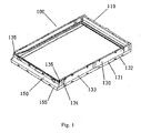
- the window frame 100 of the patent comprises a top part 110, a bottom part 150 and two side parts 130.
- the frame may be formed into a single piece or be assembled by separate parts, which are made from various materials.
- the top part, bottom part and side parts are mould from aluminum alloy or plastic, or other metal or nonmetal composite materials.
- an operative surface 153 is extended from the top edge 151 of the front surface (the outward facing exterior surface) of bottom part 150 gradually downward to the bottom edge 152. It cooperates with a flashing part (not shown) that is connected to the frame.
- the operative surface 153 can cooperate well with the window members; in particular with the flashing part (not shown) having a curved surface, it also provides good support and protection of the flashing part, and improves the drainage of the window.
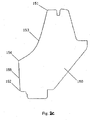
- Figs. 2a - 2c show a part of the window frame incorporated respectively with operative surfaces which are concave.
- the front surface of the bottom part 150 (the exterior surface of the bottom 150 facing outward) in Figs. 2a-2c extends forward and gradually downward from the top edge 151 to the front bottom edge 152 of the bottom part.
- the operative surface 153 can well cooperate with the corresponding window members, especially with the flashing part to provide a good support and protection of the flashing part, and hence an improved waterproof and drainage with the window.
- This thickness determines the position of the perimeter basic edge of the frame exterior surface.
- the operative surface 153 is concave as in Figs. 2a and 2b
- the preferable operative surface is such a concave one as shown in Fig. 2a , so that it can be easily installed and cooperate with other members.
- Fig. 2b shows that a cross section of the concave surface is profiled by straight lines.
- the operative surface 153 is extended from the top edge 151 of the front surface (the outward facing exterior surface) of bottom part 150 gradually downward to the bottom edge 152. It cooperates with with the flashing part (not shown) having a curved surface, it also provides good support and protection of the flashing part, and improves the drainage of the window.
- Fig. 2c shows that the cross section of the concave surface is curved.
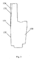
- the operative surface 153 of the bottom part 150 extends from the front edge 154 outwards beyond the bottom covering 450 connected with the sash 200, as shown in Fig. 5 .
- the operative surface 153 extends from the top edge 151 to the front surface edge 154 and outwards exceeds the exterior surface of the bottom covering 450.
- This extended surface well protects the bottom covering 450, provides an expanded supporting area for the flashing part, and facilitates the rain drainage.
- the sash bottom covering 450 also covers the frame bottom covering 350.
- the front surface edge 154 is the bottom edge of the operative surface 153 but it may be also the top edge 154 of the second front surface 155 of the horizontal part.
- the operative surface 153 shown in Fig. 2 is located at the bottom part of the window frame or it may also be located at the top part of the frame, or both at the top part and at the bottom part.
- perimeter basic edge 131 at the exterior surface of the frame 100, as shown in Fig. 1 .
- the position of the basic edge 131 can be determined by the position of the top edge 151 of the operative surface 153 at the exterior surface.
- the exterior of the frame 100 has a perimeter basic edge 131 along which a sloped exterior surface is configured.
- a sloped exterior surface As the exterior sloped surface 133 shown in Fig. 1 , 3 , the exterior sloped surface 113 in Fig. 4 .
- the exterior sloped surface is at the top part 110 and the two side parts 130 of the frame at the same time in this embodiment of the invention.
- supporters 134, 114 protruding from the slopes and allow the frame remain erect.
- the supporters 134, 114 allow the finished frame to stand upright on the floor steadily.
- the supporting area of the supporters 134, 114 may be plane or line-shaped. It may be a plane for a bigger supporting area. There are a plurality of supporters 134, 114 lined apart from each other; which facilitates the stability of the frame.
- the supporters may comprise a plurality of dot-shaped, point-shaped surfaces and/or line-shaped surfaces, as shown in Figs. 4a and 4b .
- the supporters 134, 114 are at the side part 130, top part 110 respectively.
- the preferred way is to arrange an upright supporting pillar (not shown) at the bottom end 135 of the two side parts, while the bottom plane of the pillar is at the level of the bottom surface of the bottom part 150.
- the interior structure of the horizontal part (including the top part and bottom part) and side parts of the frame 100 in Fig. 6 consists of the exterior layer and the interior layer 3, the exterior layer is the coating, and the interior layer is wooded.
- the coating can give the wood a good protection.
- the coating consists of two layers, one layer is PUR 1 and the other is paint 2.
- the paint layer 2 strengthens and protects the coating.
- the thickness of the PUR is variable/various about the interior layer 3 from thick to thin or from thin to thick.
- the sloped roofwindow in Fig. 7 consists of a window frame 100 and a sash 200 according to the present invention.
Landscapes
- Engineering & Computer Science (AREA)
- Architecture (AREA)
- Civil Engineering (AREA)
- Structural Engineering (AREA)
- Wing Frames And Configurations (AREA)
- Body Structure For Vehicles (AREA)
- Window Of Vehicle (AREA)
- Seal Device For Vehicle (AREA)
Abstract
Description
- The invention relates to a window frame used to install a window and to a sloped roof window according to the preambles of
claims 1 and 10, respectively. Such window frames and windows are known eg. fromWO 98/22684 - To construct a window in a sloped roof, first need to install the frame in the roof by means of supporters, then fit the sash with glass on the frame, with the frame and the sash covered with a covering and a flashing part and some other necessary parts.
- The combination of the frame, the sash with other means or parts and the combination of the frame with the sash satisfies people's normal use of the window constructed in the sloped roof.
- Apparently, all the parts of the window, especially the frame is very important, the structure of the frame and other parts determine for the entire window the production process, production cost, installation, connection, seal, waterproof, flashing part, usage and maintenance and so on.
- Generally, the frame and the top, bottom and outward facing side part of the sash is covered to protect the wood material of the frame and the sash, so that the weather for example the rain, the sun, or the blizzard does not erode the wood or other material of the frame or sash. The sash covering comprises top covering, side covering and bottom covering, the sash bottom covering covers the outward facing side of the bottom part thereof. In order to cover the bottom part of the sash, the bottom covering is exposed in the air. Particularly after the installation of the exterior vertical side of the bottom covering on the sash, it will be easily scratched by other sharp and hard material during transportation, installation, utilization and maintenance, or damaged by the friction with the floor or the wall, This severely will cause the failure of the bottom covering and reduces its life. Meanwhile it brings the inconvenience to the utilization and maintenance, increases the production costs and consumes costs. For example, in the
application WO99/51830 - In the
application WO99/51831 - Besides, for the flashing part, which connects to the frame bottom covering, is entirely constructed in the air at the outward front side of the frame bottom. With a slight collision by the parts, it may cause the unsteadiness of the flashing part. Plus the flashing part is usually made of light metal or complex material, the collision between parts or heavier force tends to deform the flashing parts, thus jeopardize the usage thereof.
- Under certain circumstance, it is necessary to configure vertically several windows in the sloped roof, this needs to connect the two vertically adjacent windows, and then waterproof and drain the lower combination part of the upper window and the upper combination part of the lower window. Due to the limitation of the aforesaid frame structure, it will cause the same unreasonable waterproof and drainage in the combination part.
- Nowadays, with the development of the material technology, some high intensity, water resistant, erosion resistant material is used on the frame and the sash, it may lead to an increase of the material costs; the consumption needs in different areas will vary with the weather and the environment. The change of the production will lead to change of the window parts, increase of the production costs. To lower the costs, improve the performance, make it more competitive, make the production of the window frame simpler and more convenience, cut down the material cost to its maximum extent without decreasing the technical performance, all are the real problems people longing for solutions.
- In order to overcome the disadvantage of the prior art, the purpose of the present invention is to provide a frame structure which can well cooperate with the window parts.
- Another purpose of the present invention is to provide a frame structure, which effectively protect the sash bottom covering.
- Another purpose of the present invention is to provide a frame structure, which easily connects the adjacent vertically lined windows.
- Another purpose of the present invention is to provide a frame structure, which is low cost, convenient made.
- Another purpose of the present invention is to provide a sloped roofwindow, which comprises a window frame according to the invention.
- Therefore, the present invention provides a window frame, according to
claim 1 and a sloped-roof window according to claim 10. - Additional preferable features of said window frame and said sloped-roof window are contained in
dependent claims 2 to 9 and 11 to 17 respectively. -
-
Fig. 1 is a perspective view of an embodiment of a window frame according to the invention; -
Fig. 2a is a cross section of the bottom part inFig. 1 ; -
Figs.2b - 2c are a cross section of the bottom part according to other embodiments of the invention; -
Fig. 3 is a cross section of the side part inFig. 1 ; -
Fig. 4 is the cross section of the top part inFig. 1 ; -
Fig. 5 is the cross section of the entire assembly including the frame bottom part, sash bottom part and the covering; -
Fig. 6 is a partial cross section view of the frame interior structure according to the invention; -
Fig. 7 is a perspective view of the window according to the invention. - The invention will now be explained in detail in the following with reference to the drawings and embodiment:
- Referring to
Fig. 1 , thewindow frame 100 of the patent comprises atop part 110, abottom part 150 and twoside parts 130. The frame may be formed into a single piece or be assembled by separate parts, which are made from various materials. For example, the top part, bottom part and side parts are mould from aluminum alloy or plastic, or other metal or nonmetal composite materials. - As shown in
Fig. 2a , anoperative surface 153 is extended from thetop edge 151 of the front surface (the outward facing exterior surface) ofbottom part 150 gradually downward to thebottom edge 152. It cooperates with a flashing part (not shown) that is connected to the frame. Theoperative surface 153 can cooperate well with the window members; in particular with the flashing part (not shown) having a curved surface, it also provides good support and protection of the flashing part, and improves the drainage of the window. -
Figs. 2a - 2c show a part of the window frame incorporated respectively with operative surfaces which are concave. The front surface of the bottom part 150 (the exterior surface of thebottom 150 facing outward) inFigs. 2a-2c extends forward and gradually downward from thetop edge 151 to thefront bottom edge 152 of the bottom part. Between thetop edge 151 and thebottom edge 152 of the bottom part is at least oneoperative surface 153 provided for cooperating with a flashing part (not shown) connected with the frame. Theoperative surface 153 can well cooperate with the corresponding window members, especially with the flashing part to provide a good support and protection of the flashing part, and hence an improved waterproof and drainage with the window. - This thickness determines the position of the perimeter basic edge of the frame exterior surface.
- The
operative surface 153 is concave as inFigs. 2a and2b The preferable operative surface is such a concave one as shown inFig. 2a , so that it can be easily installed and cooperate with other members. -
Fig. 2b shows that a cross section of the concave surface is profiled by straight lines. - As shown in
Fig. 2a , theoperative surface 153 is extended from thetop edge 151 of the front surface (the outward facing exterior surface) ofbottom part 150 gradually downward to thebottom edge 152. It cooperates with with the flashing part (not shown) having a curved surface, it also provides good support and protection of the flashing part, and improves the drainage of the window. -
Fig. 2c shows that the cross section of the concave surface is curved. - The
operative surface 153 of thebottom part 150 extends from thefront edge 154 outwards beyond the bottom covering 450 connected with thesash 200, as shown inFig. 5 . Thus, theoperative surface 153 extends from thetop edge 151 to thefront surface edge 154 and outwards exceeds the exterior surface of the bottom covering 450. This extended surface well protects the bottom covering 450, provides an expanded supporting area for the flashing part, and facilitates the rain drainage. InFig. 5 , the sash bottom covering 450 also covers the frame bottom covering 350. - The
front surface edge 154 is the bottom edge of theoperative surface 153 but it may be also thetop edge 154 of the secondfront surface 155 of the horizontal part. - The
operative surface 153 shown inFig. 2 is located at the bottom part of the window frame or it may also be located at the top part of the frame, or both at the top part and at the bottom part. - When the
frame 100 is integrated by molding, there is perimeterbasic edge 131 at the exterior surface of theframe 100, as shown inFig. 1 . The position of thebasic edge 131 can be determined by the position of thetop edge 151 of theoperative surface 153 at the exterior surface. There is configured a slope along thebasic edge 131 facing inwards at the exterior surface of the frame, as theslope 155 shown inFig. 1 ,2a , theslope 132 shown inFig. 1 ,3 and theslope 112 shown inFig. 4 ., It facilitates the demolding production of the frame. - In
Fig. 1 , the exterior of theframe 100 has a perimeterbasic edge 131 along which a sloped exterior surface is configured. As the exterior slopedsurface 133 shown inFig. 1 ,3 , the exterior slopedsurface 113 inFig. 4 . The exterior sloped surface is at thetop part 110 and the twoside parts 130 of the frame at the same time in this embodiment of the invention. - On the
side part 130 inFig. 3 and the exterior slopedsurface top part 110 inFig. 4 , there are formedsupporters supporters - The supporting area of the
supporters supporters - The supporters may comprise a plurality of dot-shaped, point-shaped surfaces and/or line-shaped surfaces, as shown in
Figs. 4a and 4b . - The
supporters side part 130,top part 110 respectively. In the case of the operative surface configured at the bottom part of the frame, the preferred way is to arrange an upright supporting pillar (not shown) at thebottom end 135 of the two side parts, while the bottom plane of the pillar is at the level of the bottom surface of thebottom part 150. - The interior structure of the horizontal part (including the top part and bottom part) and side parts of the
frame 100 inFig. 6 consists of the exterior layer and theinterior layer 3, the exterior layer is the coating, and the interior layer is wooded. The coating can give the wood a good protection. The coating consists of two layers, one layer isPUR 1 and the other ispaint 2. Thepaint layer 2 strengthens and protects the coating. The thickness of the PUR is variable/various about theinterior layer 3 from thick to thin or from thin to thick. - The sloped roofwindow in
Fig. 7 consists of awindow frame 100 and asash 200 according to the present invention.
Claims (17)
- A window frame (100), comprising at least one bottom part (150), which has a top surface edge (151) and an exterior side going downwards, extending to the bottom surface edge (152) of the bottom part, and where the top surface edge and the bottom surface edge between them creates an operative surface (153), adapted to work together with a flashing part (350), which is connected to the frame, wherein the operative surface of the bottom part extends forward so as to, when a sash is mounted on the frame, enable it to exceed a bottom covering (450) of the sash, so that it protects the covering characterized in that the operative surface is placed within the upper part of the front of the bottom part, and creates a first front surface of the bottom part, and a second front surface (155) between a front surface edge (154) being the bottom edge of the operative surface and the bottom surface edge, wherein the operative surface is concave, wherein the cross-section of the concave surface is profiled by straight lines, by straight and curved lines or by curved lines.
- A window frame according to claim 1, wherein an operative surface is placed also at the top part (110) of the frame and/or also at the side parts (130) of the frame, wherein the exterior of the frame has a perimeter basic edge along which a sloped exterior surface is configured.
- A window frame according to any of the preceding claims, wherein frame supporters (114,134) are configured on the sloped or concave exterior surface protruding therefrom.
- A window frame according to claim 3, wherein the frame supporters (114,134) are dot-shaped, point-shaped or line-shaped or combinations thereof.
- A window frame according to claim 3 or 4, wherein the members of frame supporters (114,134) are apart from each other.
- A window frame according to any of claims 3-5, wherein the frame supporters (114,134) at least are placed at two ends of the lengths of the top part (110) or side parts (130) of the frame.
- A window frame according to any of the preceding claims, wherein the cross-section of the bottom (150), top (110) or side parts (130) of the frame comprises a shell with an exterior layer (1,2) and an interior layer (3), where the exterior layer is preferably a coating and the interior layer is preferably wood.
- A window frame according to claim 7, wherein the coating consists of two layers, one (1) preferably being PUR, and the other (2) preferably being paint.
- A window frame according to claim 7 or 8, wherein the thickness of the one layer (1) varies along the perimeter of the interior layer (3) in certain areas from thick to thin.
- A sloped-roof window, comprising a frame (100), a sash (200) and a covering, in which the frame and the sash comprises top (110), bottom (150,250) and side parts (130), having a top surface edge (151) and an exterior side going downwards, extending to the bottom surface edge (152) of the bottom part of the frame, and where the top surface edge and the bottom surface edge between them creates an operative surface (153), adapted to working together with a flashing part (350), which is connected to the frame, wherein the operative surface of the bottom part of the frame extends forward to exceed the bottom covering (450) of the sash, so that it protects the covering, characterized in that the operative surface is placed within the upper part of the front of the bottom part of the frame, and creates a first front surface of the bottom part, and a second front surface (155) between a front surface edge (154) being the bottom edge of the operative surface and the bottom edge of the bottom surface edge, wherein the operative surface is concave, wherein the cross-section of the concave surface is profiled by straight and/or curved lines.
- A sloped-roof window according to claim 10, wherein an operative surface is placed at the side parts (130) and/or the top part (110) of the frame, wherein the exterior of the frame has perimeter basic edge along which a sloped exterior surface is configured.
- A sloped-roof window according to claim 10 or 11, wherein frame supporters (114,134) are configured on the sloped or concave exterior surface protruding therefrom.
- A sloped-roof window according to claim 12, wherein the frame supporter surfaces are point-shaped or line-shaped or combinations thereof
- A sloped-roof window according to claim 12 or 13, wherein the members of frame supporters are apart from each other.
- A sloped-roof window according to any of claims 10-14, wherein the cross-section of the top (110), bottom (150) or side parts (130) of the frame consist of exterior layer (1,2) and interior layer (3), where the exterior layer is preferably a coating and the interior layer is preferably wood.
- A sloped-roof window according to claim 15, wherein the coating (1,2) consists of two layers, one (1) preferably being PUR, and the other (2) preferably being paint.
- A sloped-roof window according to claim 16, wherein the thickness of the one layer (1) varies along the perimeter of the interior layer (3) in certain areas from thick to thin.
Priority Applications (1)
| Application Number | Priority Date | Filing Date | Title |
|---|---|---|---|
| PL04388079T PL1533438T3 (en) | 2003-11-21 | 2004-11-20 | Roofwindow frame structure and roofwindow |
Applications Claiming Priority (6)
| Application Number | Priority Date | Filing Date | Title |
|---|---|---|---|
| CN200310115369 | 2003-11-21 | ||
| CN200320121966 | 2003-11-21 | ||
| CN 200320121966 CN2714683Y (en) | 2003-11-21 | 2003-11-21 | Easily produced inclined roof window frame |
| CN200320121967 | 2003-11-21 | ||
| CNB2003101153699A CN100526575C (en) | 2003-11-21 | 2003-11-21 | Pitched roof sky-light frame structure and its pitched roof sky-light |
| CN 200320121967 CN2801938Y (en) | 2003-11-21 | 2003-11-21 | Frame of hip dormer window |
Publications (3)
| Publication Number | Publication Date |
|---|---|
| EP1533438A2 EP1533438A2 (en) | 2005-05-25 |
| EP1533438A3 EP1533438A3 (en) | 2008-03-26 |
| EP1533438B1 true EP1533438B1 (en) | 2010-07-28 |
Family
ID=34437459
Family Applications (1)
| Application Number | Title | Priority Date | Filing Date |
|---|---|---|---|
| EP04388079A Ceased EP1533438B1 (en) | 2003-11-21 | 2004-11-20 | Roofwindow frame structure and roofwindow |
Country Status (4)
| Country | Link |
|---|---|
| EP (1) | EP1533438B1 (en) |
| AT (1) | ATE475757T1 (en) |
| DE (1) | DE602004028330D1 (en) |
| PL (1) | PL1533438T3 (en) |
Cited By (1)
| Publication number | Priority date | Publication date | Assignee | Title |
|---|---|---|---|---|
| DE102011102912A1 (en) * | 2011-05-31 | 2012-12-06 | Roto Frank Ag | Apartment skylight has inner surface and outer surface that are bent parallel to axes, such that normal of inner surface and outer surface are positioned at specific angle with frame plane |
Family Cites Families (3)
| Publication number | Priority date | Publication date | Assignee | Title |
|---|---|---|---|---|
| SE330249B (en) * | 1969-01-08 | 1970-11-09 | Foerenade Tak Ab | |
| US4776141A (en) * | 1987-03-02 | 1988-10-11 | Powell J William | Skylights |
| DK173828B1 (en) * | 1996-11-19 | 2001-12-03 | Vkr Holding As | Window, especially for mounting on a sloping roof surface |
-
2004
- 2004-11-20 PL PL04388079T patent/PL1533438T3/en unknown
- 2004-11-20 EP EP04388079A patent/EP1533438B1/en not_active Ceased
- 2004-11-20 DE DE602004028330T patent/DE602004028330D1/en not_active Expired - Lifetime
- 2004-11-20 AT AT04388079T patent/ATE475757T1/en not_active IP Right Cessation
Cited By (2)
| Publication number | Priority date | Publication date | Assignee | Title |
|---|---|---|---|---|
| DE102011102912A1 (en) * | 2011-05-31 | 2012-12-06 | Roto Frank Ag | Apartment skylight has inner surface and outer surface that are bent parallel to axes, such that normal of inner surface and outer surface are positioned at specific angle with frame plane |
| DE102011102912B4 (en) | 2011-05-31 | 2021-12-16 | Roto Frank Ag | Skylights, frames and casement frames and methods of manufacturing the same |
Also Published As
| Publication number | Publication date |
|---|---|
| DE602004028330D1 (en) | 2010-09-09 |
| EP1533438A3 (en) | 2008-03-26 |
| EP1533438A2 (en) | 2005-05-25 |
| PL1533438T3 (en) | 2011-01-31 |
| ATE475757T1 (en) | 2010-08-15 |
Similar Documents
| Publication | Publication Date | Title |
|---|---|---|
| CA2227896A1 (en) | Window frame assembly | |
| EP1697612B1 (en) | Drainage system in a roofwindow and roofwindow | |
| JP4067570B2 (en) | Windows for mounting on sloped roofs in particular | |
| EP1533436B1 (en) | Covering sealing element for roof window | |
| EP1533438B1 (en) | Roofwindow frame structure and roofwindow | |
| JP4641872B2 (en) | Building fence | |
| JP3037267B2 (en) | Cosmetic materials for overhanging parts and windows around buildings | |
| US20100015909A1 (en) | Truss vent cover with selective size adjustability | |
| CN100526575C (en) | Pitched roof sky-light frame structure and its pitched roof sky-light | |
| KR102520319B1 (en) | Expansion method and pergola roof expansion rescus | |
| JPS6229571Y2 (en) | ||
| JP2880946B2 (en) | Building eaves structure | |
| JP4048206B2 (en) | Cap and parting cap material and cap wood | |
| EP1536080A2 (en) | Frame for a roof window and roof window | |
| JPH1162029A (en) | Waterproof structure of building outer wall | |
| JPS6246736Y2 (en) | ||
| JP3096439B2 (en) | Drainage structure of composite sash | |
| JPS6320728Y2 (en) | ||
| JPH0111907Y2 (en) | ||
| JPH11229512A (en) | Fitting structure for wall side flashing | |
| JPH0619747Y2 (en) | Bay window | |
| JPS6317820Y2 (en) | ||
| JPH0543145Y2 (en) | ||
| JP2007303178A (en) | Vertical facing exterior materials for buildings and vertical facing exterior structures | |
| JPH06288031A (en) | Eaves |
Legal Events
| Date | Code | Title | Description |
|---|---|---|---|
| PUAI | Public reference made under article 153(3) epc to a published international application that has entered the european phase |
Free format text: ORIGINAL CODE: 0009012 |
|
| AK | Designated contracting states |
Kind code of ref document: A2 Designated state(s): AT BE BG CH CY CZ DE DK EE ES FI FR GB GR HU IE IS IT LI LU MC NL PL PT RO SE SI SK TR |
|
| AX | Request for extension of the european patent |
Extension state: AL HR LT LV MK YU |
|
| RAP1 | Party data changed (applicant data changed or rights of an application transferred) |
Owner name: VKR HOLDING A/S |
|
| PUAL | Search report despatched |
Free format text: ORIGINAL CODE: 0009013 |
|
| AK | Designated contracting states |
Kind code of ref document: A3 Designated state(s): AT BE BG CH CY CZ DE DK EE ES FI FR GB GR HU IE IS IT LI LU MC NL PL PT RO SE SI SK TR |
|
| AX | Request for extension of the european patent |
Extension state: AL HR LT LV MK YU |
|
| 17P | Request for examination filed |
Effective date: 20080401 |
|
| AKX | Designation fees paid |
Designated state(s): AT BE BG CH CY CZ DE DK EE ES FI FR GB GR HU IE IS IT LI LU MC NL PL PT RO SE SI SK TR |
|
| 17Q | First examination report despatched |
Effective date: 20090624 |
|
| GRAP | Despatch of communication of intention to grant a patent |
Free format text: ORIGINAL CODE: EPIDOSNIGR1 |
|
| GRAS | Grant fee paid |
Free format text: ORIGINAL CODE: EPIDOSNIGR3 |
|
| GRAA | (expected) grant |
Free format text: ORIGINAL CODE: 0009210 |
|
| AK | Designated contracting states |
Kind code of ref document: B1 Designated state(s): AT BE BG CH CY CZ DE DK EE ES FI FR GB GR HU IE IS IT LI LU MC NL PL PT RO SE SI SK TR |
|
| REG | Reference to a national code |
Ref country code: GB Ref legal event code: FG4D |
|
| REG | Reference to a national code |
Ref country code: CH Ref legal event code: EP |
|
| REG | Reference to a national code |
Ref country code: IE Ref legal event code: FG4D |
|
| REF | Corresponds to: |
Ref document number: 602004028330 Country of ref document: DE Date of ref document: 20100909 Kind code of ref document: P |
|
| REG | Reference to a national code |
Ref country code: NL Ref legal event code: VDEP Effective date: 20100728 |
|
| PG25 | Lapsed in a contracting state [announced via postgrant information from national office to epo] |
Ref country code: NL Free format text: LAPSE BECAUSE OF FAILURE TO SUBMIT A TRANSLATION OF THE DESCRIPTION OR TO PAY THE FEE WITHIN THE PRESCRIBED TIME-LIMIT Effective date: 20100728 Ref country code: FI Free format text: LAPSE BECAUSE OF FAILURE TO SUBMIT A TRANSLATION OF THE DESCRIPTION OR TO PAY THE FEE WITHIN THE PRESCRIBED TIME-LIMIT Effective date: 20100728 Ref country code: AT Free format text: LAPSE BECAUSE OF FAILURE TO SUBMIT A TRANSLATION OF THE DESCRIPTION OR TO PAY THE FEE WITHIN THE PRESCRIBED TIME-LIMIT Effective date: 20100728 |
|
| REG | Reference to a national code |
Ref country code: PL Ref legal event code: T3 |
|
| PG25 | Lapsed in a contracting state [announced via postgrant information from national office to epo] |
Ref country code: SI Free format text: LAPSE BECAUSE OF FAILURE TO SUBMIT A TRANSLATION OF THE DESCRIPTION OR TO PAY THE FEE WITHIN THE PRESCRIBED TIME-LIMIT Effective date: 20100728 Ref country code: IS Free format text: LAPSE BECAUSE OF FAILURE TO SUBMIT A TRANSLATION OF THE DESCRIPTION OR TO PAY THE FEE WITHIN THE PRESCRIBED TIME-LIMIT Effective date: 20101128 Ref country code: CY Free format text: LAPSE BECAUSE OF FAILURE TO SUBMIT A TRANSLATION OF THE DESCRIPTION OR TO PAY THE FEE WITHIN THE PRESCRIBED TIME-LIMIT Effective date: 20100728 Ref country code: BG Free format text: LAPSE BECAUSE OF FAILURE TO SUBMIT A TRANSLATION OF THE DESCRIPTION OR TO PAY THE FEE WITHIN THE PRESCRIBED TIME-LIMIT Effective date: 20101028 Ref country code: PT Free format text: LAPSE BECAUSE OF FAILURE TO SUBMIT A TRANSLATION OF THE DESCRIPTION OR TO PAY THE FEE WITHIN THE PRESCRIBED TIME-LIMIT Effective date: 20101129 |
|
| PG25 | Lapsed in a contracting state [announced via postgrant information from national office to epo] |
Ref country code: GR Free format text: LAPSE BECAUSE OF FAILURE TO SUBMIT A TRANSLATION OF THE DESCRIPTION OR TO PAY THE FEE WITHIN THE PRESCRIBED TIME-LIMIT Effective date: 20101029 Ref country code: BE Free format text: LAPSE BECAUSE OF FAILURE TO SUBMIT A TRANSLATION OF THE DESCRIPTION OR TO PAY THE FEE WITHIN THE PRESCRIBED TIME-LIMIT Effective date: 20100728 Ref country code: SE Free format text: LAPSE BECAUSE OF FAILURE TO SUBMIT A TRANSLATION OF THE DESCRIPTION OR TO PAY THE FEE WITHIN THE PRESCRIBED TIME-LIMIT Effective date: 20100728 |
|
| PG25 | Lapsed in a contracting state [announced via postgrant information from national office to epo] |
Ref country code: DK Free format text: LAPSE BECAUSE OF FAILURE TO SUBMIT A TRANSLATION OF THE DESCRIPTION OR TO PAY THE FEE WITHIN THE PRESCRIBED TIME-LIMIT Effective date: 20100728 |
|
| PG25 | Lapsed in a contracting state [announced via postgrant information from national office to epo] |
Ref country code: IT Free format text: LAPSE BECAUSE OF FAILURE TO SUBMIT A TRANSLATION OF THE DESCRIPTION OR TO PAY THE FEE WITHIN THE PRESCRIBED TIME-LIMIT Effective date: 20100728 Ref country code: CZ Free format text: LAPSE BECAUSE OF FAILURE TO SUBMIT A TRANSLATION OF THE DESCRIPTION OR TO PAY THE FEE WITHIN THE PRESCRIBED TIME-LIMIT Effective date: 20100728 Ref country code: EE Free format text: LAPSE BECAUSE OF FAILURE TO SUBMIT A TRANSLATION OF THE DESCRIPTION OR TO PAY THE FEE WITHIN THE PRESCRIBED TIME-LIMIT Effective date: 20100728 Ref country code: RO Free format text: LAPSE BECAUSE OF FAILURE TO SUBMIT A TRANSLATION OF THE DESCRIPTION OR TO PAY THE FEE WITHIN THE PRESCRIBED TIME-LIMIT Effective date: 20100728 Ref country code: SK Free format text: LAPSE BECAUSE OF FAILURE TO SUBMIT A TRANSLATION OF THE DESCRIPTION OR TO PAY THE FEE WITHIN THE PRESCRIBED TIME-LIMIT Effective date: 20100728 |
|
| PLBE | No opposition filed within time limit |
Free format text: ORIGINAL CODE: 0009261 |
|
| STAA | Information on the status of an ep patent application or granted ep patent |
Free format text: STATUS: NO OPPOSITION FILED WITHIN TIME LIMIT |
|
| PG25 | Lapsed in a contracting state [announced via postgrant information from national office to epo] |
Ref country code: MC Free format text: LAPSE BECAUSE OF NON-PAYMENT OF DUE FEES Effective date: 20101130 Ref country code: ES Free format text: LAPSE BECAUSE OF FAILURE TO SUBMIT A TRANSLATION OF THE DESCRIPTION OR TO PAY THE FEE WITHIN THE PRESCRIBED TIME-LIMIT Effective date: 20101108 |
|
| REG | Reference to a national code |
Ref country code: CH Ref legal event code: PL |
|
| 26N | No opposition filed |
Effective date: 20110429 |
|
| PG25 | Lapsed in a contracting state [announced via postgrant information from national office to epo] |
Ref country code: LI Free format text: LAPSE BECAUSE OF NON-PAYMENT OF DUE FEES Effective date: 20101130 Ref country code: CH Free format text: LAPSE BECAUSE OF NON-PAYMENT OF DUE FEES Effective date: 20101130 |
|
| REG | Reference to a national code |
Ref country code: DE Ref legal event code: R097 Ref document number: 602004028330 Country of ref document: DE Effective date: 20110429 |
|
| PG25 | Lapsed in a contracting state [announced via postgrant information from national office to epo] |
Ref country code: IE Free format text: LAPSE BECAUSE OF NON-PAYMENT OF DUE FEES Effective date: 20101120 |
|
| PG25 | Lapsed in a contracting state [announced via postgrant information from national office to epo] |
Ref country code: HU Free format text: LAPSE BECAUSE OF FAILURE TO SUBMIT A TRANSLATION OF THE DESCRIPTION OR TO PAY THE FEE WITHIN THE PRESCRIBED TIME-LIMIT Effective date: 20110129 Ref country code: LU Free format text: LAPSE BECAUSE OF NON-PAYMENT OF DUE FEES Effective date: 20101120 |
|
| PG25 | Lapsed in a contracting state [announced via postgrant information from national office to epo] |
Ref country code: TR Free format text: LAPSE BECAUSE OF FAILURE TO SUBMIT A TRANSLATION OF THE DESCRIPTION OR TO PAY THE FEE WITHIN THE PRESCRIBED TIME-LIMIT Effective date: 20100728 |
|
| REG | Reference to a national code |
Ref country code: FR Ref legal event code: PLFP Year of fee payment: 12 |
|
| REG | Reference to a national code |
Ref country code: FR Ref legal event code: PLFP Year of fee payment: 13 |
|
| REG | Reference to a national code |
Ref country code: FR Ref legal event code: PLFP Year of fee payment: 14 |
|
| REG | Reference to a national code |
Ref country code: FR Ref legal event code: PLFP Year of fee payment: 15 |
|
| PGFP | Annual fee paid to national office [announced via postgrant information from national office to epo] |
Ref country code: FR Payment date: 20181026 Year of fee payment: 15 Ref country code: GB Payment date: 20181114 Year of fee payment: 15 |
|
| GBPC | Gb: european patent ceased through non-payment of renewal fee |
Effective date: 20191120 |
|
| PG25 | Lapsed in a contracting state [announced via postgrant information from national office to epo] |
Ref country code: GB Free format text: LAPSE BECAUSE OF NON-PAYMENT OF DUE FEES Effective date: 20191120 Ref country code: FR Free format text: LAPSE BECAUSE OF NON-PAYMENT OF DUE FEES Effective date: 20191130 |
|
| PGFP | Annual fee paid to national office [announced via postgrant information from national office to epo] |
Ref country code: PL Payment date: 20201013 Year of fee payment: 17 |
|
| PGFP | Annual fee paid to national office [announced via postgrant information from national office to epo] |
Ref country code: DE Payment date: 20211005 Year of fee payment: 18 |
|
| PG25 | Lapsed in a contracting state [announced via postgrant information from national office to epo] |
Ref country code: PL Free format text: LAPSE BECAUSE OF NON-PAYMENT OF DUE FEES Effective date: 20211120 |
|
| REG | Reference to a national code |
Ref country code: DE Ref legal event code: R119 Ref document number: 602004028330 Country of ref document: DE |
|
| PG25 | Lapsed in a contracting state [announced via postgrant information from national office to epo] |
Ref country code: DE Free format text: LAPSE BECAUSE OF NON-PAYMENT OF DUE FEES Effective date: 20230601 |