EP1533438A2 - Roofwindow frame structure and roofwindow - Google Patents
Roofwindow frame structure and roofwindow Download PDFInfo
- Publication number
- EP1533438A2 EP1533438A2 EP04388079A EP04388079A EP1533438A2 EP 1533438 A2 EP1533438 A2 EP 1533438A2 EP 04388079 A EP04388079 A EP 04388079A EP 04388079 A EP04388079 A EP 04388079A EP 1533438 A2 EP1533438 A2 EP 1533438A2
- Authority
- EP
- European Patent Office
- Prior art keywords
- frame
- edge
- sloped
- exterior
- horizontal
- Prior art date
- Legal status (The legal status is an assumption and is not a legal conclusion. Google has not performed a legal analysis and makes no representation as to the accuracy of the status listed.)
- Granted
Links
Images


Classifications
-
- E—FIXED CONSTRUCTIONS
- E04—BUILDING
- E04D—ROOF COVERINGS; SKY-LIGHTS; GUTTERS; ROOF-WORKING TOOLS
- E04D13/00—Special arrangements or devices in connection with roof coverings; Protection against birds; Roof drainage ; Sky-lights
- E04D13/03—Sky-lights; Domes; Ventilating sky-lights
- E04D13/035—Sky-lights; Domes; Ventilating sky-lights characterised by having movable parts
- E04D13/0351—Sky-lights; Domes; Ventilating sky-lights characterised by having movable parts the parts pivoting about a fixed axis
- E04D13/0354—Sky-lights; Domes; Ventilating sky-lights characterised by having movable parts the parts pivoting about a fixed axis the parts being flat
-
- E—FIXED CONSTRUCTIONS
- E04—BUILDING
- E04D—ROOF COVERINGS; SKY-LIGHTS; GUTTERS; ROOF-WORKING TOOLS
- E04D13/00—Special arrangements or devices in connection with roof coverings; Protection against birds; Roof drainage ; Sky-lights
- E04D13/03—Sky-lights; Domes; Ventilating sky-lights
- E04D13/0305—Supports or connecting means for sky-lights of flat or domed shape
- E04D13/031—Supports or connecting means for sky-lights of flat or domed shape characterised by a frame for connection to an inclined roof
Definitions
- the invention relates to a window frame used to install a window; in particular it relates to a frame structure and a roof window constructed in a sloped roof.
- the combination of the frame, the sash with other means or parts and the combination of the frame with the sash satisfies people's normal use of the window constructed in the sloped roof.
- the structure of the frame and other parts determine for the entire window the production process, production cost, installation, connection, seal, waterproof, flashing part, usage and maintenance and so on.
- the frame and the top, bottom and outward facing side part of the sash is covered to protect the wood material of the frame and the sash, so that the weather for example the rain, the sun, or the blizzard erodes the wood or other material of the frame or sash.
- the sash covering comprises top covering, side covering and bottom covering, the sash bottom covering covers the outward facing side of the bottom part thereof.
- the bottom covering in order to cover the bottom part of the sash, the bottom covering is exposed in the air, particularly after the installation of the exterior vertical side of the bottom covering on the sash, it will be easily scratched by other sharp and hard material during transportation, installation, utilization and maintenance, or damaged by the friction with the floor or the wall, severely will cause the failure of the bottom covering and reduces its life. Meanwhile it brings the inconvenience to the utilization and maintenance, increase the production costs and consume costs.
- the application WO99/51830 "AN OPENABLE WINDOW WITH MAIN FRAME AND SASH COVERING MEMBERS", the covering member in its published specification is the like.
- the flashing part which connects to the frame bottom covering, is entirely constructed in the air at the outward front side of the frame bottom. With a slight collision by the parts, it may cause the unsteadiness of the flashing part. Plus the flashing part is usually made of light metal or complex material, the collision between parts or heavier force tends to deform the flashing parts, thus jeopardize the usage thereof.
- the purpose of the present invention is to provide a frame structure which can well cooperate with the window parts.
- Another purpose of the present invention is to provide a frame structure, which effectively protect the sash bottom covering.
- Another purpose of the present invention is to provide a frame structure, which easily connects the adjacent vertically lined windows.
- Another purpose of the present invention is to provide a frame structure, which is low cost, convenient made.
- Another purpose of the present invention is to provide a sloped roofwindow, which comprises a window frame according to the invention.
- a window frame comprising at least one horizontal part, which has a top surface edge going downwards on the exterior side, extending to the bottom edge of the horizontal part, and where the top surface edge and the bottom surface edge between them creates a operative surface, adapted to working together with a flashing part, which is connected to the frame.
- the operative surface is placed within the upper part of the front of the horizontal part, and creates a first front surface of the horizontal frame, and a second front surface between the bottom edge of the operative surface and the bottom edge of the bottom surface edge.
- the operative surface is convex and/or sloped or concave.
- the crosssection of the convex, concave or sloped surface is profiled by straight lines.
- the crosssection of the convex, concave or sloped surface is profiled by straight and curved lines.
- the crosssection of the convex, concave or sloped surface is profiled by curved lines.
- the operative surface of the horizontal frame extends forward to exceed the bottom covering of the sash, so that it protects the covering well.
- the front face edge is the bottom edge of the operative surface.
- the operative surface is placed at the bottom part of the frame.
- the operative surface is placed at the bottom part of the frame.
- the operative surface is placed at the top part of the frame.
- the operative surface is placed at the top part of the frame.
- the exterior of the frame has a perimeter basic edge along which a sloped exterior surface is configured.
- the sloped exterior surface is placed at the horizontal or vertical parts of the frame.
- the sloped exterior surface is placed at the top part and side parts.
- the frame supporters are configured on the sloped exterior surface protruding therefrom (in order to keep it standing upright).
- the supporter surfaces can be point-shaped or line-shaped or combinations thereof.
- the members of supporters are apart from each other.
- the supporters are placed at the top, bottom or side parts or combinations thereof.
- the supporters at least are placed at two ends of the lengths of the top part or side parts of the frame.
- the crosssection of the horizontal parts or side parts of the frame are consists of exterior layer and interior layer and the exterior layer is coating and the interior layer is wood.
- the coating consists of two layers, one is PUR, and the other is paint.
- the thickness of the PUR layer is variable/various along the wood perimeter in certain areas from thick to thin to save the material for making the frame.
- the present invention also provides a sloped-roof window, comprising a frame, a sash and a covering, in which the frame and the sash are constitutive of horizontal and side parts, the horizontal parts comprising top part and bottom part, characterized having a top surface edge going downwards on the exterior side, extending to the bottom edge of the horizontal part, and where the top surface edge and the bottom surface edge between them creates a operative surface, adapted to working together with a flashing part, which is connected to the frame.
- the operative surface is placed within the upper part of the front of the horizontal frame, and creates a first front surface of the horizontal frame, and a second front surface between the bottom edge of the operative surface and the bottom edge of the bottom surface edge.
- the operative surface is convex and/or sloped or concave.
- the crosssection of the convex, concave or sloped surface is profiled by straight and /or curved lines.
- the operative surface of the horizontal frame extends forward to exceed the bottom covering of the sash, so that it protects the covering well.
- the front face edge is the bottom edge of the operative surface.
- the operative surface is placed at the bottom part and/or the top part of the frame.
- the exterior of the frame has a perimeter basic edge along which a sloped exterior surface is configured.
- the sloped exterior surface is placed at the top part and side parts.
- the frame supporters are configured on the sloped exterior surface protruding therefrom (in order to keep it standing upright).
- the supporter surfaces can be point-shaped or line-shaped or combinations thereof.
- the members of supporters are apart from each other.
- the supporters are placed at the top, bottom or side or combinations thereof.
- the crosssection of the horizontal parts or side parts of the frame consists of exterior layer and interior layer and the exterior layer is coating and the interior layer is wood.
- the coating consists of two layers, one is PUR, and the other is paint.
- the thickness of the PUR layer is variable/various along the wood perimeter in certain areas from thick to thin to save the material for making the frame.
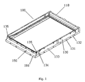
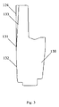
- the window frame 100 of the utility model comprises a top part 110, a bottom part 150 and two side parts 130.
- the frame may be formed into a single piece or be assembled by separate parts, which are made from various materials.
- the top part, bottom part and side parts are mould from aluminum alloy or plastic, or other metal or nonmetal composite materials.
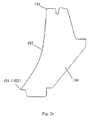
- an operative surface 153 is extended from the top edge 151 of the front surface (the outward facing exterior surface) of bottom part 150 gradually downward to the bottom edge 152. It cooperates with a flashing part (not shown) that is connected to the frame.
- the operative surface 153 can cooperate well with the window members; in particular with the flashing part (not shown) having a curved surface, it also provides good support and protection of the flashing part, and improves the drainage of the window.
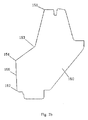
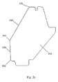
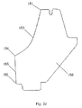
- Figs. 2a - 2e show a part of the window frame incorporated respectively with operative surfaces which are concave and sloped.
- the operative surface may be convex according to another embodiment.
- the front surface of the bottom part 150 (the exterior surface of the bottom 150 facing outward) in Figs. 2a-2e extends forward and gradually downward from the top edge 151 to the front bottom edge 152 of the bottom part.
- Between the top edge 151 and the bottom edge 152 of the bottom part is at least one operative surface 153 provided for cooperating with a flashing part (not shown) connected with the frame.
- the operative surface 153 can well cooperate with the corresponding window members, especially with the flashing part to provide a good support and protection of the flashing part, and hence an improved waterproof and drainage with the window.
- This thickness determines the position of the perimeter basic edge of the frame exterior surface.
- the operative surface 153 may be concave in Figs. 2a and 2b or sloped in Fig. 2c, depending on actual requirements.
- the preferable operative surface is such a concave one as shown in Fig. 2a, so that it can be easily installed and cooperate with other members.
- Fig. 2b shows that a cross section of the concave surface is profiled by straight lines.
- the operative surface 153 is extended from the top edge 151 of the front surface (the outward facing exterior surface) of bottom part 150 gradually downward to the bottom edge 152. It cooperates with with the flashing part (not shown) having a curved surface, it also provides good support and protection of the flashing part, and improves the drainage of the window.
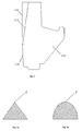
- Fig. 2d shows that the cross section of the concave surface is curved.
- the operative surface 153 of the bottom part 150 extends from the front edge 154 outwards beyond the bottom covering 450 connected with the sash 200, as shown in Fig. 5.
- the operative surface 153 extends from the top edge 151 to the front surface edge 154 and outwards exceeds the exterior surface of the bottom covering 450.
- This extended surface well protects the bottom covering 450, provides an expanded supporting area for the flashing part, and facilitates the rain drainage.
- the sash bottom covering 450 also covers the frame bottom covering 350.
- the front surface edge 154 may be the bottom edge of the operative surface 153, or it may be the top edge 154 of the second front surface 155 of the horizontal part. When the second front surface is removed, the front surface edge 154 is the bottom edge of the operative surface 153, or the front bottom edge 152 of the bottom part 150.
- Fig 2 shows such an embodiment.
- the operative surface 153 shown in Fig. 2 is located at the top part of the window frame or it may also be located at the top part of the frame, or both at the top part and at the bottom part.
- perimeter basic edge 131 at the exterior surface of the frame 100, as shown in Fig. 1.
- the position of the basic edge 131 can be determined by the position of the top edge 151 of the operative surface 153 at the exterior surface.
- the exterior of the frame 100 has a perimeter basic edge 131 along which a sloped exterior surface is configured.
- the exterior sloped surface is at the top part 110 and the two side parts 130 of the frame at the same time in this embodiment of the invention.
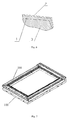
- the supporting area of the supporters 134, 114 may be plane or line-shaped. It may be a plane for a bigger supporting area. There are a plurality of supporters 134, 114 lined apart from each other; which facilitates the stability of the frame.
- the supporters may comprise a plurality of dot-shaped, point-shaped surfaces and/or line-shaped surfaces, as shown in Figs. 4a and 4b.
- the supporters 134, 114 are at the side part 130, top part 110 respectively.
- the preferred way is to arrange an upright supporting pillar (not shown) at the bottom end 135 of the two side parts, while the bottom plane of the pillar is at the level of the bottom surface of the bottom part 150.
- the interior structure of the horizontal part (including the top part and bottom part) and side parts of the frame 100 in Fig. 6 consists of the exterior layer and the interior layer 3, the exterior layer is the coating, and the interior layer is wooded.
- the coating can give the wood a good protection.
- the coating consists of two layers, one layer is PUR 1 and the other is paint 2.
- the paint layer 2 strengthens and protects the coating.
- the thickness of the PUR is variable/various about the interior layer 3 from thick to thin or from thin to thick.
- the sloped roofwindow in Fig. 7 consists of a window frame 100 and a sash 200 according to the present invention.
Landscapes
- Engineering & Computer Science (AREA)
- Architecture (AREA)
- Civil Engineering (AREA)
- Structural Engineering (AREA)
- Wing Frames And Configurations (AREA)
- Body Structure For Vehicles (AREA)
- Window Of Vehicle (AREA)
- Seal Device For Vehicle (AREA)
Abstract
Description
Claims (10)
- A window frame, comprising at least one horizontal part, which has a top surface edge going downwards on the exterior side, extending to the bottom edge of the horizontal part, and where the top surface edge and the bottom surface edge between them creates a operative surface, adapted to working together with a flashing part, which is connected to the frame.
- A window frame according to claim 1, wherein the operative surface is placed within the upper part of the front of the horizontal part, and creates a first front surface of the horizontal frame, and a second front surface between the bottom edge of the operative surface and the bottom edge of the bottom surface edge, wherein the operative surface can be convex and/or sloped or concave, wherein the crosssection of the convex, concave or sloped surface can be profiled by straight lines, wherein the crosssection of the convex, concave or sloped surface can be profiled by straight and curved lines, wherein the crosssection of the convex, concave or sloped surface can be profiled by curved lines.
- A window frame according to any of the preceding claims, wherein the operative surface of the horizontal frame extends forward to exceed the bottom covering of the sash, so that it protects the covering well.
- A window frame according to any of the preceding claims, wherein the front face edge is the bottom edge of the operative surface, wherein the operative surface can be placed at the bottom part of the frame, wherein the operative surface can be placed at the bottom part of the frame, wherein the operative surface can be placed at the top part of the frame, wherein the operative surface can be placed at the top part of the frame, wherein the exterior of the frame has a perimeter basic edge along which a sloped exterior surface can be configured, wherein the sloped exterior surface can be placed at the horizontal or vertical parts of the frame, wherein the sloped exterior surface canbe placed at the top part and side parts.
- A window frame according to any of the preceding claims, wherein the frame supporters are configured on the sloped exterior surface protruding therefrom (in order to keep it standing upright), wherein the supporter surfaces can be dot-shaped, point-shaped or line-shaped or combinations thereof, wherein the members of supporters can be apart from each other, wherein the supporters canbe placed at the top, bottom or side parts or combinations thereof, wherein the supporters at least can be placed at two ends of the lengths of the top part or side parts of the frame.
- A window frame according to any of the preceding claims, wherein the crosssection of the horizontal parts or side parts of the frame comprises a shell with an exterior layer and an interior layer where the exterior layer can be a coating and the interior layer can be wood, wherein the coating consists of two layers, one can be PUR, and the other can be paint, wherein the thickness of the PUR layer can be variable/various along the wood perimeter in certain areas from thick to thin to save the material for making the frame.
- A sloped-roof window, comprising a frame, a sash and a covering, in which the frame and the sash constitute horizontal and side parts, the horizontal parts comprising top part and bottom part, characterized having a top surface edge going downwards on the exterior side, extending to the bottom edge of the horizontal part, and where the top surface edge and the bottom surface edge between them creates a operative surface, adapted to working together with a flashing part, which is connected to the frame.
- A sloped-roof window according to claim 7, wherein the operative surface is placed within the upper part of the front of the horizontal frame, and creates a first front surface of the horizontal frame, and a second front surface between the bottom edge of the operative surface and the bottom edge of the bottom surface edge, wherein the operative surface can be convex and/or sloped or concave, wherein the crosssection of the convex, concave or sloped surface can be profiled by straight and /or curved lines.
- A sloped-roof window according to any of the preceding claims, wherein the operative surface of the horizontal frame extends forward to exceed the bottom covering of the sash, so that it protects the covering in a good way, wherein the front face edge can be the bottom edge of the operative surface, wherein the operative surface can be placed at the bottom part and/or the top part of the frame, wherein the exterior of the frame has perimeter basic edge along which a sloped exterior surface can be configured, wherein the sloped exterior surface can be placed at the top part and side parts, wherein the frame supporters can be configured on the sloped exterior surface protruding therefrom (in order to keep it standing upright), wherein the supporter surfaces can be point-shaped or line-shaped or combinations thereof, wherein the members of supporters can be apart from each other, wherein the supporters can be placed at the top, bottom or side or combinations thereof.
- A sloped-roof window according to any of the preceding claims, wherein the crosssection of the horizontal parts or side parts of the frame consists of exterior layer and interior layer and the exterior layer can be a coating and the interior layer can be wood, wherein the coating consists of two layers, one can be PUR, and the other can be paint, wherein the thickness of the PUR layer can be variable/various along the wood perimeter in certain areas from thick to thin to save the material for making the frame.
Priority Applications (1)
| Application Number | Priority Date | Filing Date | Title |
|---|---|---|---|
| PL04388079T PL1533438T3 (en) | 2003-11-21 | 2004-11-20 | Roofwindow frame structure and roofwindow |
Applications Claiming Priority (6)
| Application Number | Priority Date | Filing Date | Title |
|---|---|---|---|
| CN200310115369 | 2003-11-21 | ||
| CN200320121966 | 2003-11-21 | ||
| CN 200320121966 CN2714683Y (en) | 2003-11-21 | 2003-11-21 | Easily produced inclined roof window frame |
| CN200320121967 | 2003-11-21 | ||
| CNB2003101153699A CN100526575C (en) | 2003-11-21 | 2003-11-21 | Pitched roof sky-light frame structure and its pitched roof sky-light |
| CN 200320121967 CN2801938Y (en) | 2003-11-21 | 2003-11-21 | Frame of hip dormer window |
Publications (3)
| Publication Number | Publication Date |
|---|---|
| EP1533438A2 true EP1533438A2 (en) | 2005-05-25 |
| EP1533438A3 EP1533438A3 (en) | 2008-03-26 |
| EP1533438B1 EP1533438B1 (en) | 2010-07-28 |
Family
ID=34437459
Family Applications (1)
| Application Number | Title | Priority Date | Filing Date |
|---|---|---|---|
| EP04388079A Ceased EP1533438B1 (en) | 2003-11-21 | 2004-11-20 | Roofwindow frame structure and roofwindow |
Country Status (4)
| Country | Link |
|---|---|
| EP (1) | EP1533438B1 (en) |
| AT (1) | ATE475757T1 (en) |
| DE (1) | DE602004028330D1 (en) |
| PL (1) | PL1533438T3 (en) |
Families Citing this family (1)
| Publication number | Priority date | Publication date | Assignee | Title |
|---|---|---|---|---|
| DE102011102912B4 (en) * | 2011-05-31 | 2021-12-16 | Roto Frank Ag | Skylights, frames and casement frames and methods of manufacturing the same |
Family Cites Families (3)
| Publication number | Priority date | Publication date | Assignee | Title |
|---|---|---|---|---|
| SE330249B (en) * | 1969-01-08 | 1970-11-09 | Foerenade Tak Ab | |
| US4776141A (en) * | 1987-03-02 | 1988-10-11 | Powell J William | Skylights |
| DK173828B1 (en) * | 1996-11-19 | 2001-12-03 | Vkr Holding As | Window, especially for mounting on a sloping roof surface |
-
2004
- 2004-11-20 PL PL04388079T patent/PL1533438T3/en unknown
- 2004-11-20 EP EP04388079A patent/EP1533438B1/en not_active Ceased
- 2004-11-20 DE DE602004028330T patent/DE602004028330D1/en not_active Expired - Lifetime
- 2004-11-20 AT AT04388079T patent/ATE475757T1/en not_active IP Right Cessation
Also Published As
| Publication number | Publication date |
|---|---|
| DE602004028330D1 (en) | 2010-09-09 |
| EP1533438A3 (en) | 2008-03-26 |
| PL1533438T3 (en) | 2011-01-31 |
| EP1533438B1 (en) | 2010-07-28 |
| ATE475757T1 (en) | 2010-08-15 |
Similar Documents
| Publication | Publication Date | Title |
|---|---|---|
| JP4067570B2 (en) | Windows for mounting on sloped roofs in particular | |
| EP1533436B1 (en) | Covering sealing element for roof window | |
| EP1533438A2 (en) | Roofwindow frame structure and roofwindow | |
| JP4641872B2 (en) | Building fence | |
| US12281474B2 (en) | Eaves gutter | |
| CN211499158U (en) | Sunshine room | |
| JP3037267B2 (en) | Cosmetic materials for overhanging parts and windows around buildings | |
| US20100015909A1 (en) | Truss vent cover with selective size adjustability | |
| CN100526575C (en) | Pitched roof sky-light frame structure and its pitched roof sky-light | |
| CN217079328U (en) | Drainage structure of sunshine room ceiling | |
| JPS5915351Y2 (en) | Garari door diagonal siding | |
| CN217150960U (en) | Water tank structure | |
| KR102520319B1 (en) | Expansion method and pergola roof expansion rescus | |
| CN217379660U (en) | A anti-icing external decoration line that weighs down for building curtain | |
| CN211714907U (en) | Attractive and low-cost glass window auxiliary frame structure | |
| JPS6229571Y2 (en) | ||
| JP2880946B2 (en) | Building eaves structure | |
| JPS6246736Y2 (en) | ||
| JP2002309721A (en) | Roof structure | |
| CN2801938Y (en) | Frame of hip dormer window | |
| JPS6111423Y2 (en) | ||
| JPH11229512A (en) | Fitting structure for wall side flashing | |
| KR200400415Y1 (en) | A gutter at the rainwater eaves for zinc roof | |
| JPH037461Y2 (en) | ||
| JP2002309735A (en) | Roof structure |
Legal Events
| Date | Code | Title | Description |
|---|---|---|---|
| PUAI | Public reference made under article 153(3) epc to a published international application that has entered the european phase |
Free format text: ORIGINAL CODE: 0009012 |
|
| AK | Designated contracting states |
Kind code of ref document: A2 Designated state(s): AT BE BG CH CY CZ DE DK EE ES FI FR GB GR HU IE IS IT LI LU MC NL PL PT RO SE SI SK TR |
|
| AX | Request for extension of the european patent |
Extension state: AL HR LT LV MK YU |
|
| RAP1 | Party data changed (applicant data changed or rights of an application transferred) |
Owner name: VKR HOLDING A/S |
|
| PUAL | Search report despatched |
Free format text: ORIGINAL CODE: 0009013 |
|
| AK | Designated contracting states |
Kind code of ref document: A3 Designated state(s): AT BE BG CH CY CZ DE DK EE ES FI FR GB GR HU IE IS IT LI LU MC NL PL PT RO SE SI SK TR |
|
| AX | Request for extension of the european patent |
Extension state: AL HR LT LV MK YU |
|
| 17P | Request for examination filed |
Effective date: 20080401 |
|
| AKX | Designation fees paid |
Designated state(s): AT BE BG CH CY CZ DE DK EE ES FI FR GB GR HU IE IS IT LI LU MC NL PL PT RO SE SI SK TR |
|
| 17Q | First examination report despatched |
Effective date: 20090624 |
|
| GRAP | Despatch of communication of intention to grant a patent |
Free format text: ORIGINAL CODE: EPIDOSNIGR1 |
|
| GRAS | Grant fee paid |
Free format text: ORIGINAL CODE: EPIDOSNIGR3 |
|
| GRAA | (expected) grant |
Free format text: ORIGINAL CODE: 0009210 |
|
| AK | Designated contracting states |
Kind code of ref document: B1 Designated state(s): AT BE BG CH CY CZ DE DK EE ES FI FR GB GR HU IE IS IT LI LU MC NL PL PT RO SE SI SK TR |
|
| REG | Reference to a national code |
Ref country code: GB Ref legal event code: FG4D |
|
| REG | Reference to a national code |
Ref country code: CH Ref legal event code: EP |
|
| REG | Reference to a national code |
Ref country code: IE Ref legal event code: FG4D |
|
| REF | Corresponds to: |
Ref document number: 602004028330 Country of ref document: DE Date of ref document: 20100909 Kind code of ref document: P |
|
| REG | Reference to a national code |
Ref country code: NL Ref legal event code: VDEP Effective date: 20100728 |
|
| PG25 | Lapsed in a contracting state [announced via postgrant information from national office to epo] |
Ref country code: NL Free format text: LAPSE BECAUSE OF FAILURE TO SUBMIT A TRANSLATION OF THE DESCRIPTION OR TO PAY THE FEE WITHIN THE PRESCRIBED TIME-LIMIT Effective date: 20100728 Ref country code: FI Free format text: LAPSE BECAUSE OF FAILURE TO SUBMIT A TRANSLATION OF THE DESCRIPTION OR TO PAY THE FEE WITHIN THE PRESCRIBED TIME-LIMIT Effective date: 20100728 Ref country code: AT Free format text: LAPSE BECAUSE OF FAILURE TO SUBMIT A TRANSLATION OF THE DESCRIPTION OR TO PAY THE FEE WITHIN THE PRESCRIBED TIME-LIMIT Effective date: 20100728 |
|
| REG | Reference to a national code |
Ref country code: PL Ref legal event code: T3 |
|
| PG25 | Lapsed in a contracting state [announced via postgrant information from national office to epo] |
Ref country code: SI Free format text: LAPSE BECAUSE OF FAILURE TO SUBMIT A TRANSLATION OF THE DESCRIPTION OR TO PAY THE FEE WITHIN THE PRESCRIBED TIME-LIMIT Effective date: 20100728 Ref country code: IS Free format text: LAPSE BECAUSE OF FAILURE TO SUBMIT A TRANSLATION OF THE DESCRIPTION OR TO PAY THE FEE WITHIN THE PRESCRIBED TIME-LIMIT Effective date: 20101128 Ref country code: CY Free format text: LAPSE BECAUSE OF FAILURE TO SUBMIT A TRANSLATION OF THE DESCRIPTION OR TO PAY THE FEE WITHIN THE PRESCRIBED TIME-LIMIT Effective date: 20100728 Ref country code: BG Free format text: LAPSE BECAUSE OF FAILURE TO SUBMIT A TRANSLATION OF THE DESCRIPTION OR TO PAY THE FEE WITHIN THE PRESCRIBED TIME-LIMIT Effective date: 20101028 Ref country code: PT Free format text: LAPSE BECAUSE OF FAILURE TO SUBMIT A TRANSLATION OF THE DESCRIPTION OR TO PAY THE FEE WITHIN THE PRESCRIBED TIME-LIMIT Effective date: 20101129 |
|
| PG25 | Lapsed in a contracting state [announced via postgrant information from national office to epo] |
Ref country code: GR Free format text: LAPSE BECAUSE OF FAILURE TO SUBMIT A TRANSLATION OF THE DESCRIPTION OR TO PAY THE FEE WITHIN THE PRESCRIBED TIME-LIMIT Effective date: 20101029 Ref country code: BE Free format text: LAPSE BECAUSE OF FAILURE TO SUBMIT A TRANSLATION OF THE DESCRIPTION OR TO PAY THE FEE WITHIN THE PRESCRIBED TIME-LIMIT Effective date: 20100728 Ref country code: SE Free format text: LAPSE BECAUSE OF FAILURE TO SUBMIT A TRANSLATION OF THE DESCRIPTION OR TO PAY THE FEE WITHIN THE PRESCRIBED TIME-LIMIT Effective date: 20100728 |
|
| PG25 | Lapsed in a contracting state [announced via postgrant information from national office to epo] |
Ref country code: DK Free format text: LAPSE BECAUSE OF FAILURE TO SUBMIT A TRANSLATION OF THE DESCRIPTION OR TO PAY THE FEE WITHIN THE PRESCRIBED TIME-LIMIT Effective date: 20100728 |
|
| PG25 | Lapsed in a contracting state [announced via postgrant information from national office to epo] |
Ref country code: IT Free format text: LAPSE BECAUSE OF FAILURE TO SUBMIT A TRANSLATION OF THE DESCRIPTION OR TO PAY THE FEE WITHIN THE PRESCRIBED TIME-LIMIT Effective date: 20100728 Ref country code: CZ Free format text: LAPSE BECAUSE OF FAILURE TO SUBMIT A TRANSLATION OF THE DESCRIPTION OR TO PAY THE FEE WITHIN THE PRESCRIBED TIME-LIMIT Effective date: 20100728 Ref country code: EE Free format text: LAPSE BECAUSE OF FAILURE TO SUBMIT A TRANSLATION OF THE DESCRIPTION OR TO PAY THE FEE WITHIN THE PRESCRIBED TIME-LIMIT Effective date: 20100728 Ref country code: RO Free format text: LAPSE BECAUSE OF FAILURE TO SUBMIT A TRANSLATION OF THE DESCRIPTION OR TO PAY THE FEE WITHIN THE PRESCRIBED TIME-LIMIT Effective date: 20100728 Ref country code: SK Free format text: LAPSE BECAUSE OF FAILURE TO SUBMIT A TRANSLATION OF THE DESCRIPTION OR TO PAY THE FEE WITHIN THE PRESCRIBED TIME-LIMIT Effective date: 20100728 |
|
| PLBE | No opposition filed within time limit |
Free format text: ORIGINAL CODE: 0009261 |
|
| STAA | Information on the status of an ep patent application or granted ep patent |
Free format text: STATUS: NO OPPOSITION FILED WITHIN TIME LIMIT |
|
| PG25 | Lapsed in a contracting state [announced via postgrant information from national office to epo] |
Ref country code: MC Free format text: LAPSE BECAUSE OF NON-PAYMENT OF DUE FEES Effective date: 20101130 Ref country code: ES Free format text: LAPSE BECAUSE OF FAILURE TO SUBMIT A TRANSLATION OF THE DESCRIPTION OR TO PAY THE FEE WITHIN THE PRESCRIBED TIME-LIMIT Effective date: 20101108 |
|
| REG | Reference to a national code |
Ref country code: CH Ref legal event code: PL |
|
| 26N | No opposition filed |
Effective date: 20110429 |
|
| PG25 | Lapsed in a contracting state [announced via postgrant information from national office to epo] |
Ref country code: LI Free format text: LAPSE BECAUSE OF NON-PAYMENT OF DUE FEES Effective date: 20101130 Ref country code: CH Free format text: LAPSE BECAUSE OF NON-PAYMENT OF DUE FEES Effective date: 20101130 |
|
| REG | Reference to a national code |
Ref country code: DE Ref legal event code: R097 Ref document number: 602004028330 Country of ref document: DE Effective date: 20110429 |
|
| PG25 | Lapsed in a contracting state [announced via postgrant information from national office to epo] |
Ref country code: IE Free format text: LAPSE BECAUSE OF NON-PAYMENT OF DUE FEES Effective date: 20101120 |
|
| PG25 | Lapsed in a contracting state [announced via postgrant information from national office to epo] |
Ref country code: HU Free format text: LAPSE BECAUSE OF FAILURE TO SUBMIT A TRANSLATION OF THE DESCRIPTION OR TO PAY THE FEE WITHIN THE PRESCRIBED TIME-LIMIT Effective date: 20110129 Ref country code: LU Free format text: LAPSE BECAUSE OF NON-PAYMENT OF DUE FEES Effective date: 20101120 |
|
| PG25 | Lapsed in a contracting state [announced via postgrant information from national office to epo] |
Ref country code: TR Free format text: LAPSE BECAUSE OF FAILURE TO SUBMIT A TRANSLATION OF THE DESCRIPTION OR TO PAY THE FEE WITHIN THE PRESCRIBED TIME-LIMIT Effective date: 20100728 |
|
| REG | Reference to a national code |
Ref country code: FR Ref legal event code: PLFP Year of fee payment: 12 |
|
| REG | Reference to a national code |
Ref country code: FR Ref legal event code: PLFP Year of fee payment: 13 |
|
| REG | Reference to a national code |
Ref country code: FR Ref legal event code: PLFP Year of fee payment: 14 |
|
| REG | Reference to a national code |
Ref country code: FR Ref legal event code: PLFP Year of fee payment: 15 |
|
| PGFP | Annual fee paid to national office [announced via postgrant information from national office to epo] |
Ref country code: FR Payment date: 20181026 Year of fee payment: 15 Ref country code: GB Payment date: 20181114 Year of fee payment: 15 |
|
| GBPC | Gb: european patent ceased through non-payment of renewal fee |
Effective date: 20191120 |
|
| PG25 | Lapsed in a contracting state [announced via postgrant information from national office to epo] |
Ref country code: GB Free format text: LAPSE BECAUSE OF NON-PAYMENT OF DUE FEES Effective date: 20191120 Ref country code: FR Free format text: LAPSE BECAUSE OF NON-PAYMENT OF DUE FEES Effective date: 20191130 |
|
| PGFP | Annual fee paid to national office [announced via postgrant information from national office to epo] |
Ref country code: PL Payment date: 20201013 Year of fee payment: 17 |
|
| PGFP | Annual fee paid to national office [announced via postgrant information from national office to epo] |
Ref country code: DE Payment date: 20211005 Year of fee payment: 18 |
|
| PG25 | Lapsed in a contracting state [announced via postgrant information from national office to epo] |
Ref country code: PL Free format text: LAPSE BECAUSE OF NON-PAYMENT OF DUE FEES Effective date: 20211120 |
|
| REG | Reference to a national code |
Ref country code: DE Ref legal event code: R119 Ref document number: 602004028330 Country of ref document: DE |
|
| PG25 | Lapsed in a contracting state [announced via postgrant information from national office to epo] |
Ref country code: DE Free format text: LAPSE BECAUSE OF NON-PAYMENT OF DUE FEES Effective date: 20230601 |