EP1533240B1 - Reclosable opening device for sealed sheet material packages of pourable food products - Google Patents
Reclosable opening device for sealed sheet material packages of pourable food products Download PDFInfo
- Publication number
- EP1533240B1 EP1533240B1 EP20030425740 EP03425740A EP1533240B1 EP 1533240 B1 EP1533240 B1 EP 1533240B1 EP 20030425740 EP20030425740 EP 20030425740 EP 03425740 A EP03425740 A EP 03425740A EP 1533240 B1 EP1533240 B1 EP 1533240B1
- Authority
- EP
- European Patent Office
- Prior art keywords
- cap
- thread
- package
- frame
- threads
- Prior art date
- Legal status (The legal status is an assumption and is not a legal conclusion. Google has not performed a legal analysis and makes no representation as to the accuracy of the status listed.)
- Expired - Lifetime
Links
- 235000013305 food Nutrition 0.000 title claims description 18
- 239000000463 material Substances 0.000 title description 14
- 238000005520 cutting process Methods 0.000 claims description 49
- 238000010008 shearing Methods 0.000 claims description 8
- 230000001052 transient effect Effects 0.000 claims description 5
- 239000005022 packaging material Substances 0.000 description 16
- 239000004033 plastic Substances 0.000 description 9
- 229920003023 plastic Polymers 0.000 description 9
- 230000004888 barrier function Effects 0.000 description 7
- 239000007789 gas Substances 0.000 description 7
- 239000004698 Polyethylene Substances 0.000 description 4
- 239000002657 fibrous material Substances 0.000 description 4
- -1 polyethylene Polymers 0.000 description 4
- 229920000573 polyethylene Polymers 0.000 description 4
- 230000005540 biological transmission Effects 0.000 description 3
- 238000007789 sealing Methods 0.000 description 3
- 238000003860 storage Methods 0.000 description 3
- QVGXLLKOCUKJST-UHFFFAOYSA-N atomic oxygen Chemical compound [O] QVGXLLKOCUKJST-UHFFFAOYSA-N 0.000 description 2
- 238000005304 joining Methods 0.000 description 2
- 235000020191 long-life milk Nutrition 0.000 description 2
- 239000001301 oxygen Substances 0.000 description 2
- 229910052760 oxygen Inorganic materials 0.000 description 2
- 238000004806 packaging method and process Methods 0.000 description 2
- 230000035515 penetration Effects 0.000 description 2
- 230000002093 peripheral effect Effects 0.000 description 2
- 230000002035 prolonged effect Effects 0.000 description 2
- 230000000284 resting effect Effects 0.000 description 2
- 230000000717 retained effect Effects 0.000 description 2
- 241001391944 Commicarpus scandens Species 0.000 description 1
- MHAJPDPJQMAIIY-UHFFFAOYSA-N Hydrogen peroxide Chemical compound OO MHAJPDPJQMAIIY-UHFFFAOYSA-N 0.000 description 1
- 235000007688 Lycopersicon esculentum Nutrition 0.000 description 1
- 240000003768 Solanum lycopersicum Species 0.000 description 1
- 239000000853 adhesive Substances 0.000 description 1
- 230000001070 adhesive effect Effects 0.000 description 1
- 239000004411 aluminium Substances 0.000 description 1
- XAGFODPZIPBFFR-UHFFFAOYSA-N aluminium Chemical compound [Al] XAGFODPZIPBFFR-UHFFFAOYSA-N 0.000 description 1
- 229910052782 aluminium Inorganic materials 0.000 description 1
- 239000005030 aluminium foil Substances 0.000 description 1
- 239000006071 cream Substances 0.000 description 1
- 230000000694 effects Effects 0.000 description 1
- 235000015203 fruit juice Nutrition 0.000 description 1
- 238000010438 heat treatment Methods 0.000 description 1
- 239000007788 liquid Substances 0.000 description 1
- 238000004519 manufacturing process Methods 0.000 description 1
- 238000000034 method Methods 0.000 description 1
- 235000013336 milk Nutrition 0.000 description 1
- 239000008267 milk Substances 0.000 description 1
- 210000004080 milk Anatomy 0.000 description 1
- 235000015067 sauces Nutrition 0.000 description 1
- 230000035807 sensation Effects 0.000 description 1
- 238000007493 shaping process Methods 0.000 description 1
- 230000001954 sterilising effect Effects 0.000 description 1
- 238000004659 sterilization and disinfection Methods 0.000 description 1
- 239000003206 sterilizing agent Substances 0.000 description 1
- 239000000126 substance Substances 0.000 description 1
- 235000014101 wine Nutrition 0.000 description 1
- 235000013618 yogurt Nutrition 0.000 description 1
Images

Classifications
-
- B—PERFORMING OPERATIONS; TRANSPORTING
- B65—CONVEYING; PACKING; STORING; HANDLING THIN OR FILAMENTARY MATERIAL
- B65D—CONTAINERS FOR STORAGE OR TRANSPORT OF ARTICLES OR MATERIALS, e.g. BAGS, BARRELS, BOTTLES, BOXES, CANS, CARTONS, CRATES, DRUMS, JARS, TANKS, HOPPERS, FORWARDING CONTAINERS; ACCESSORIES, CLOSURES, OR FITTINGS THEREFOR; PACKAGING ELEMENTS; PACKAGES
- B65D5/00—Rigid or semi-rigid containers of polygonal cross-section, e.g. boxes, cartons or trays, formed by folding or erecting one or more blanks made of paper
- B65D5/42—Details of containers or of foldable or erectable container blanks
- B65D5/72—Contents-dispensing means
- B65D5/74—Spouts
- B65D5/746—Spouts formed separately from the container
- B65D5/747—Spouts formed separately from the container with means for piercing or cutting the container wall or a membrane connected to said wall
- B65D5/748—Spouts formed separately from the container with means for piercing or cutting the container wall or a membrane connected to said wall a major part of the container wall or membrane being left inside the container after the opening
Definitions
- the present invention relates to a reclosable opening device for sealed sheet material packages of pourable food products.
- pourable food products such as fruit juice, UHT (ultra-high-temperature-treated) milk, wine, tomato sauce, etc.
- UHT ultra-high-temperature-treated milk
- wine tomato sauce
- etc. are sold in packages made of sterilized sheet packaging material.
- a typical example of this type of package is the parallelepiped-shaped package for liquid or pourable food products known as Tetra Brik Aseptic (registered trademark), which is made by folding and sealing a web of laminated packaging material.
- the packaging material has a multilayer structure comprising a layer of fibrous material, e.g. paper, covered on both sides with layers of heat-seal plastic material, e.g.
- polyethylene and, in the case of aseptic packages for long-storage products, such as UHT milk, also comprises a layer of oxygen-barrier material, defined, for example, by aluminium foil, which is superimposed on a layer of heat-seal plastic material, and is in turn covered with another layer of heat-seal plastic material eventually defining the inner face of the package contacting the food product.
- a layer of oxygen-barrier material defined, for example, by aluminium foil
- Such packages are normally produced on fully automatic packaging machines, on which a continuous tube is formed from the web-fed packaging material; the web of packaging material is sterilized on the packaging machine itself, e.g. by applying a chemical sterilizing agent, such as a hydrogen peroxide solution, which, once sterilization is completed, is removed, e.g. vapourized by heating, from the surfaces of the packaging material; and the web of packaging material so sterilized is kept in a closed, sterile environment, and is folded and sealed longitudinally to form a vertical tube.
- a chemical sterilizing agent such as a hydrogen peroxide solution
- the tube is filled with the sterilized or sterile-processed food product, and is sealed and cut along equally spaced transverse sections to form pillow packs, which are then folded mechanically to form the finished, e.g. substantially parallelepiped-shaped, packages.
- the packaging material may be cut into blanks, which are folded on forming spindles into packages, which are then filled with the food product and sealed.
- the so-called "gable-top” package known by the trade name Tetra Rex (registered trademark).
- packages of the above type have been fitted with reclosable opening devices, which substantially comprise a frame defining an opening and fitted about a hole or a pierceable or removable portion in a wall of the package; and a cap hinged to the frame.
- the cap is normally molded integrally with the frame, and is initially sealed to it, along a peripheral edge surrounding the opening, by a thin breakable annular connecting portion. Once unsealed, the cap is movable between a closed position, in which it cooperates hermetically with the frame, and an open position.
- threaded caps separate from and initially screwed to the frame, are also used.
- opening devices of the above type are made of easy-to-break plastic material, normally polyethylene.
- Polyethylene however, has the drawback of being a poor oxygen barrier. Consequently, the side of the packaging material eventually defining the inside of the package must be fitted over the hole with an additional "patch" element defined by a small sheet of heat-seal plastic material, and the opposite side of the packaging material must be fitted with an oxygen-barrier element, e.g. a pull-off tab, which is heat sealed to the patch element and provided with a layer of aluminium.
- an oxygen-barrier element e.g. a pull-off tab
- Providing the packages with barrier and patch elements involves additional processing of the packaging material before it is sterilized and folded and sealed to form the vertical tube, thus increasing production time and cost of the packages.
- the user must also remove the barrier element for access to the content of the package.
- Reclosable opening devices have therefore been proposed, by which to unseal the package in one operation, while at the same time acting as an effective oxygen barrier.
- opening devices of this type substantially comprise a frame defined by a cylindrical collar defining a pour opening, and by a base flange fitted about a pierceable portion of the package; a removable cap which screws onto the outside of the collar of the frame to close the opening; and a substantially tubular cutting member, which screws inside the collar of the frame, and comprises, at one end, a cutting edge with one or more end teeth which cooperate with the pierceable portion of the package to detach it incompletely from the relative wall, i.e. all except a small-angle portion.
- the cap is normally molded integrally with a relative tamperproof ring connected coaxially to the cap by breakable radial connecting spots.
- the cap described is pressed onto the frame so that the relative tamperproof ring clicks past the thread portion of the frame close to the base flange.
- the cutting member is operated by the cap by means of ratchet-type one-way transmission means, which are activated when disengaging the cap from the collar.
- the cutting member moves in a spiral, with respect to the frame, from a raised rest position, in which its cutting edge faces the pierceable portion, to successive lowered cutting positions, in which the cutting edge interacts with the pierceable portion.
- the height of the opening devices applied to the packages is kept as low as possible.
- multistart cap and frame threads which also assist the user in opening and closing the package. That is, whereas single-start solutions require a full turn or slightly more of the cap, long-pitch multistart threads enable the cap to be removed completely, or fully tightened, by turning it roughly 180°.
- Short opening devices with multistart threads are unsuitable for packages containing fizzy drinks, on account of the long-pitch threaded connection failing to adequately retain the cap in opposition to the pressure produced inside the package by the gas in the product.
- the gas in the product could therefore cause the cap to be blown off the package when the pierceable portion is sheared.
- a reclosable opening device for sealed packages of pourable food products as claimed in Claim 1.
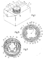
- Number 1 in Figure 1 indicates as a whole an aseptic sealed package for pourable food products, e.g. a parallelepiped-shaped package known as Tetra Brik Aseptic (registered trademark), which is made from sheet packaging material, as described previously in detail, and is fitted with a reclosable opening device 2 made of plastic material and applied to package 1 in conventional manner, e.g. using adhesives or microflame or laser sealing methods.
- Tetra Brik Aseptic registered trademark
- the packaging material has a multilayer structure, and comprises, at a top wall 3 of package 1, a circular pierceable portion 4 of axis A ( Figures 2, 4 and 5), which in use is covered externally by opening device 2 and is detached at least partly from wall 3 to enable the product to be poured out of package 1.
- the packaging material comprises a layer of fibrous material 5, normally paper, covered on the outside and inside with respective laminated sheets 6, 7 normally defined by one of more layers of heat-seal plastic material, e.g. polyethylene.
- the inner laminated sheet 7 also comprises a layer of barrier material interposed between the layers of heat-seal plastic material.
- Pierceable portion 4 is defined in this case by respective portions of outer and inner laminated sheets 6, 7 covering a hole 8, of axis A, formed in the layer of fibrous material 5.
- the pierceable portion is defined by a preferential tear line (not shown) formed in the layer of fibrous material and defined by a succession of perforations.
- a preferential tear line (not shown) formed in the layer of fibrous material and defined by a succession of perforations.
- opening device 2 comprises a frame 10 defining a through hole 11 of axis A, through which the food product is poured, and fixed to wall 3 of package 1, about pierceable portion 4; a cap 12 formed separately from frame 10 and fitted coaxially to frame 10 to close hole 11; and a tubular cutting member 13, of axis A, which engages hole 11 in axially and angularly movable manner, and is activated by cap 12 to interact with pierceable portion 4 of wall 3 to unseal package 1.
- frame 10 comprises a circular annular base flange 14, an end surface of which is fixed to wall 3 of package 1, about pierceable portion 4, and from the radially inner edge of which projects axially a cylindrical collar 16, of axis A, defining hole 11.
- collar 16 On respective opposite lateral surfaces, collar 16 comprises an external thread 20 and an internal thread 21, which, in use, engage relative threads 22, 23 of cap 12 and of cutting member 13, and slope in opposite directions with respect to axis A.
- collar 16 comprises an annular rib 24 interposed axially between one end of thread 20 and flange 14, and located a constant axial distance from flange 14.
- Collar 16 also has one or more lateral windows 18 for releasing any gas in the food product, and so reducing the pressure inside package 1, when cap 12 is unscrewed off frame 10 and shearing of pierceable portion 4 commences.
- Cap 12 is defined by a hollow cylindrical body bounded by a circular top wall 25 for closing hole 11, and by a cylindrical lateral wall 26, which projects from a peripheral edge of top wall 25, is provided internally with thread 22, and screws onto collar 16 of frame 10.
- Top wall 25 has a projecting annular rib 27 adjacent to lateral wall 26 and defining, with lateral wall 26, a seat for receiving the top end edge of collar 16.
- Cap 12 is normally molded integrally with a relative tamperproof ring 28 connected coaxially to an end edge of cap 12, opposite top wall 25, by a number of breakable radial connecting spots.
- Cap 12 is initially fixed to frame 10 in a sealing position, in which it is screwed completely onto collar 16, with its bottom end edge and tamperproof ring 28, still connected to each other, on opposite sides of rib 27 of collar 16 ( Figure 4).
- cap 12 is movable between an open position, in which it is unscrewed off collar 16 and detached from frame 10, and a closed position closing hole 11.
- Initial rotation of cap 12, when unsealing package 1, breaks the connecting spots between cap 12 and tamperproof ring 28, which rests on base flange 14. More specifically, the connecting spots are broken by spiral rotation of cap 12 away from rib 24 of frame 10, and by rib 24 simultaneously retaining tamperproof ring 28.
- cutting member 13 which has thread 23 on its outer surface, is fitted in known manner inside collar 16 of frame 10 by thread 23 engaging thread 21, and comprises an end edge 30 having face cutting means 31 - in the example shown, one cutting tooth - which cooperate with pierceable portion 4 to unseal package 1.
- Connection of collar 16 of frame 10 to cutting member 13, and operation of cutting member 13 by cap 12 are described below only as required for a clear understanding of the present invention. Further details can be found in Patent Application EP-A-1088764, the content of which is considered included herein by way of reference.
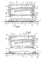
- Threads 21 and 23 define, when unsealing package 1, a helical path, of axis A, of cutting member 13 through pierceable portion 4, from a raised rest position ( Figure 4) to a bottom open position (not shown). More specifically, in the raised rest position, cutting member 13 is housed completely inside collar 16, with cutting means 31 facing pierceable portion 4; and, in the bottom open position, cutting member 13 projects axially with respect to collar 16, has penetrated a given distance inside package 1, and has completely cut pierceable portion 4, leaving it attached by a small-angle portion to wall 3.
- transmission means 32 comprise a number of first teeth 33 - four in the example shown - having a saw-tooth profile, projecting from top wall 25 of cap 12, and equally spaced angularly about axis A; and a number of second teeth 34 - eight in the example shown - also having a saw-tooth profile, and which project radially from an inner surface of cutting member 13, and mesh in axially free, angularly integral manner with teeth 33 along the release travel of cap 12 from collar 16 when unsealing package 1. More specifically, the release travel of cap 12 is shown in Figure 1 by anticlockwise rotation R of cap 12 about axis A.
- each tooth 33 is defined, towards lateral wall 26, by two oblique, outwardly converging sides 36, 37; the side (36) sloping more sharply, with respect to the radial direction joining relative tooth 33 to axis A, defines a stop for a relative tooth 34 in rotation direction R of cap 12; and the other side (37) allows teeth 34 to slide angularly in the opposite rotation direction.
- Each tooth 34 extends the full axial height of cutting member 13, and has, in cross section, the same profile as teeth 33, defined by two oblique converging sides 38, 39; and the side (38) sloping more sharply, with respect to the radial direction joining tooth 34 to axis A, faces side 36 of a relative tooth 33.
- thread 20 of frame 10 comprises, at a portion engaged by thread 22 of cap 12 at the transient stage between detachment of tamperproof ring 28 and initial shearing of pierceable portion 4 by cutting means 31, successive thread portions 40, 41 separated by a distance D1 smaller than the distance D of the rest of thread 20, so as to eliminate, at said portion, the clearance between threads 20 and 22.
- This feature enables perfect control of the rotation of cap 12 when unsealing the package, to minimize the risk of cap 12 being blown off in the case of fizzy products.
- the user experiences only one prolonged force peak when unsealing the package.
- thread 20 is a three-start type, and thread portions 40, 41 form part of independent threads.
- thread 20 may be a single-start type, and thread portions 40, 41 may be defined by spaced, facing portions of the same thread.
- the distance between thread portions 40, 41 is reduced to D1 by altering the course of one (40) of the two thread portions so that it converges towards the other (41).
- Number 2' in Figures 8 and 9 indicates as a whole a different embodiment of an opening device in accordance with the teachings of the present invention, and which is described below only insofar as it differs from opening device 2, and using the same reference numbers for component parts corresponding or equivalent to those already described.
- Opening device 2' differs from opening device 2 by the distance between thread portions 40 and 41 being reduced to D1 by shaping one (40) of the two thread portions to bring it closer to the other (41). More specifically, thread portion 40 defines a projection 42 projecting towards the adjacent thread portion 41.
- Opening device 2, 2' is assembled, before being fixed to pierceable portion 4 of package 1, by inserting cutting member 13 in a predetermined angular position inside collar 16, and by simultaneously or subsequently fitting cap 12 to frame 10.
- teeth 34 slide axially in pairs on opposite angular sides of sides 36, 37 of a relative tooth 33.
- Cap 12 is preferably pressed axially onto frame 10, after first positioning cap 12 in a predetermined angular position with respect to cutting member 13. At this stage, threads 20 and 22 engage one another, and tamperproof ring 28 clicks past annular rib 24 of collar 16 towards flange 14. Alternatively, cap 12 may be pressed axially onto the frame and then screwed on collar 16 of frame 10 into a final angular position enabling full use of the screw-off travel of cap 12 when unsealing package 1.
- cutting member 13 is in the raised rest position inside collar 16, and defines, together with cap 12 closing hole 11, a sealed configuration of opening device 2, 2' on package 1 ( Figures 4, 8).
- package 1 is unsealed by rotating cap 12 in direction R with respect to axis A to unscrew it off collar 16.
- cap 12 As cap 12 is rotated in direction R about axis A, the engagement of threads 20 and 22 simultaneously moves cap 12 axially away from wall 3, thus breaking the radial spots connecting it to tamperproof ring 28, which is retained resting axially on rib 24 of collar 16.
- Teeth 33 of cap 12 are positioned with sides 36 resting against sides 38 of relative teeth 34 of cutting member 13, which is thus also rotated about axis A in direction R.
- the axial movement of cap 12 away from wall 3 of package 1 corresponds to a simultaneous axial movement of cutting member 13 towards wall 3. More specifically, cutting member 13 is rotated by cap 12 by teeth 33 and 34 contacting at respective sides 36, 38, which are simultaneously slid axially with respect to each other by the spiral movement impressed on cap 12 and cutting member 13 by relative pairs of threads 20, 22 and 21, 23.
- Cutting means 31 advance angularly through pierceable portion 4 to detach it along its perimeter from wall 3.
- cutting member 13 is prevented from moving from the bottom open position, by teeth 33 of cap 12 being unable to reach an axial position engaging teeth 34 of cutting member 13. In which position, the sheared portion of pierceable portion 4 is retained inside cutting member 13 to keep hole 11 clear.
- Package 1 is closed by simply replacing cap 12 on collar 16.
- window/s 18 in collar 16 of frame 10 permits/permit fast release of the gas to rapidly reduce the pressure exerted on cap 12 from inside package 1, and to restore the normal axial clearance between threads 20 and 22 at the following unsealing stage, with no risk of sudden detachment of cap 12.
Description
- The present invention relates to a reclosable opening device for sealed sheet material packages of pourable food products.
- As is known, many pourable food products, such as fruit juice, UHT (ultra-high-temperature-treated) milk, wine, tomato sauce, etc., are sold in packages made of sterilized sheet packaging material.
- A typical example of this type of package is the parallelepiped-shaped package for liquid or pourable food products known as Tetra Brik Aseptic (registered trademark), which is made by folding and sealing a web of laminated packaging material. The packaging material has a multilayer structure comprising a layer of fibrous material, e.g. paper, covered on both sides with layers of heat-seal plastic material, e.g. polyethylene, and, in the case of aseptic packages for long-storage products, such as UHT milk, also comprises a layer of oxygen-barrier material, defined, for example, by aluminium foil, which is superimposed on a layer of heat-seal plastic material, and is in turn covered with another layer of heat-seal plastic material eventually defining the inner face of the package contacting the food product.
- Such packages are normally produced on fully automatic packaging machines, on which a continuous tube is formed from the web-fed packaging material; the web of packaging material is sterilized on the packaging machine itself, e.g. by applying a chemical sterilizing agent, such as a hydrogen peroxide solution, which, once sterilization is completed, is removed, e.g. vapourized by heating, from the surfaces of the packaging material; and the web of packaging material so sterilized is kept in a closed, sterile environment, and is folded and sealed longitudinally to form a vertical tube.
- The tube is filled with the sterilized or sterile-processed food product, and is sealed and cut along equally spaced transverse sections to form pillow packs, which are then folded mechanically to form the finished, e.g. substantially parallelepiped-shaped, packages.
- Alternatively, the packaging material may be cut into blanks, which are folded on forming spindles into packages, which are then filled with the food product and sealed. One example of the this type of package is the so-called "gable-top" package known by the trade name Tetra Rex (registered trademark).
- To open such packages, various solutions have been proposed, a first of which, described in Patents US 4,655,387 and US 4,410,128, comprises forming, at the corner of a flap of the package, a preferential tear line defined by a succession of perforations extending through the outer layers of the packaging material down to the layer of barrier material, and the package is opened by lifting the flap and cutting or tearing along the perforations. Once opened, packages of this type, obviously, cannot be closed, and must therefore be handled carefully to prevent spillage until all the food product in the package has been consumed.
- To eliminate this drawback, packages of the above type have been fitted with reclosable opening devices, which substantially comprise a frame defining an opening and fitted about a hole or a pierceable or removable portion in a wall of the package; and a cap hinged to the frame. The cap is normally molded integrally with the frame, and is initially sealed to it, along a peripheral edge surrounding the opening, by a thin breakable annular connecting portion. Once unsealed, the cap is movable between a closed position, in which it cooperates hermetically with the frame, and an open position. Alternatively, threaded caps, separate from and initially screwed to the frame, are also used.
- One problem encountered with opening devices of the above type is that the cap must be detachable from the frame with practically no effort when unsealing the package. For which reason, the opening devices are made of easy-to-break plastic material, normally polyethylene.
- Polyethylene, however, has the drawback of being a poor oxygen barrier. Consequently, the side of the packaging material eventually defining the inside of the package must be fitted over the hole with an additional "patch" element defined by a small sheet of heat-seal plastic material, and the opposite side of the packaging material must be fitted with an oxygen-barrier element, e.g. a pull-off tab, which is heat sealed to the patch element and provided with a layer of aluminium.
- Providing the packages with barrier and patch elements involves additional processing of the packaging material before it is sterilized and folded and sealed to form the vertical tube, thus increasing production time and cost of the packages.
- Moreover, once the cap is unsealed, the user must also remove the barrier element for access to the content of the package.
- Reclosable opening devices have therefore been proposed, by which to unseal the package in one operation, while at the same time acting as an effective oxygen barrier.
- In the solutions described in Patent Applications WO 95/05996 and EP-A-1088764 and EP 1262412, upon which the preamble of
claim 1 is based, opening devices of this type substantially comprise a frame defined by a cylindrical collar defining a pour opening, and by a base flange fitted about a pierceable portion of the package; a removable cap which screws onto the outside of the collar of the frame to close the opening; and a substantially tubular cutting member, which screws inside the collar of the frame, and comprises, at one end, a cutting edge with one or more end teeth which cooperate with the pierceable portion of the package to detach it incompletely from the relative wall, i.e. all except a small-angle portion. - The cap is normally molded integrally with a relative tamperproof ring connected coaxially to the cap by breakable radial connecting spots.
- The cap described is pressed onto the frame so that the relative tamperproof ring clicks past the thread portion of the frame close to the base flange.
- The cutting member is operated by the cap by means of ratchet-type one-way transmission means, which are activated when disengaging the cap from the collar. The cutting member moves in a spiral, with respect to the frame, from a raised rest position, in which its cutting edge faces the pierceable portion, to successive lowered cutting positions, in which the cutting edge interacts with the pierceable portion.
- When unsealing packages of the above type, the force exerted by the user on the cap is therefore discontinuous and relatively annoying. More specifically, maximum force is required at the start of the unsealing stage to detach the tamperproof ring from the cap; considerably less force is required at the subsequent rotation stage, in which, on account of the inevitable axial clearance between the cap and frame threads, the cap substantially rotates freely or "idly"; and maximum force is again required to initiate shearing of the pierceable portion by the cutting member.
- In other words, when unsealing the package, the user experiences two successive force peaks separated by a substantially free rotation stage, the effect of which is fairly annoying. That is, after the first force peak, the user is given the impression the package is unsealed, only to be called up to exert additional effort to actually complete the operation.
- Moreover, to store the finished packages and reduce the amount of plastic employed, the height of the opening devices applied to the packages is kept as low as possible.
- This is currently done using multistart cap and frame threads, which also assist the user in opening and closing the package. That is, whereas single-start solutions require a full turn or slightly more of the cap, long-pitch multistart threads enable the cap to be removed completely, or fully tightened, by turning it roughly 180°.
- Short opening devices with multistart threads, however, are unsuitable for packages containing fizzy drinks, on account of the long-pitch threaded connection failing to adequately retain the cap in opposition to the pressure produced inside the package by the gas in the product.
- The gas in the product could therefore cause the cap to be blown off the package when the pierceable portion is sheared.
- It is an object of the present invention to provide a reclosable opening device for sealed packages of pourable food products, designed to eliminate the aforementioned drawbacks typically associated with known opening devices.
- According to the present invention, there is provided a reclosable opening device for sealed packages of pourable food products, as claimed in
Claim 1. - Two preferred, non-limiting embodiments of the present invention will be described by way of example with reference to the accompanying drawings, in which:
- Figure 1 shows a view in perspective of a top portion of a sealed package for pourable food products, fitted with a reclosable opening device in accordance with the teachings of the present invention;
- Figure 2 shows a larger-scale exploded side view of the Figure 1 opening device before it is applied to the relative package;
- Figure 3 shows a larger-scale underside view in perspective of a cap of the Figure 1 opening device;
- Figures 4 and 5 show larger-scale axial sections of the Figure 1 opening device fitted to the relative package and in two different operating configurations;
- Figure 6 shows a section along line VI-VI in Figure 4;
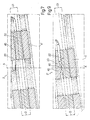
- Figure 7 shows a larger-scale detail of an externally threaded frame of the Figure 5 opening device, in which portions of the frame thread engaging respective portions of the cap thread are sectioned along the centrelines;
- Figure 8 is similar to Figure 4, and shows an alternative embodiment of an opening device in accordance with the present invention;
- Figure 9 shows the same view as in Figure 7, of the Figure 8 opening device.
-
Number 1 in Figure 1 indicates as a whole an aseptic sealed package for pourable food products, e.g. a parallelepiped-shaped package known as Tetra Brik Aseptic (registered trademark), which is made from sheet packaging material, as described previously in detail, and is fitted with areclosable opening device 2 made of plastic material and applied topackage 1 in conventional manner, e.g. using adhesives or microflame or laser sealing methods. - The packaging material has a multilayer structure, and comprises, at a
top wall 3 ofpackage 1, a circularpierceable portion 4 of axis A (Figures 2, 4 and 5), which in use is covered externally byopening device 2 and is detached at least partly fromwall 3 to enable the product to be poured out ofpackage 1. - In the example shown, the packaging material comprises a layer of
fibrous material 5, normally paper, covered on the outside and inside with respective laminatedsheets sheet 7 also comprises a layer of barrier material interposed between the layers of heat-seal plastic material. -
Pierceable portion 4 is defined in this case by respective portions of outer and inner laminatedsheets hole 8, of axis A, formed in the layer offibrous material 5. - When there is no layer of barrier material, e.g. in the case of non-aseptic packages of pasteurized products (e.g. yoghurt, cream, and other cold-storage products), the pierceable portion is defined by a preferential tear line (not shown) formed in the layer of fibrous material and defined by a succession of perforations. One example of this solution is described in Patent Application EP-A-1088764, the content of which is considered included herein by way of reference.
- With reference to Figures 1 to 6,
opening device 2 comprises aframe 10 defining a throughhole 11 of axis A, through which the food product is poured, and fixed towall 3 ofpackage 1, aboutpierceable portion 4; acap 12 formed separately fromframe 10 and fitted coaxially to frame 10 to closehole 11; and atubular cutting member 13, of axis A, which engageshole 11 in axially and angularly movable manner, and is activated bycap 12 to interact withpierceable portion 4 ofwall 3 tounseal package 1. - More specifically,
frame 10 comprises a circularannular base flange 14, an end surface of which is fixed towall 3 ofpackage 1, aboutpierceable portion 4, and from the radially inner edge of which projects axially acylindrical collar 16, of axis A, defininghole 11. - On respective opposite lateral surfaces,
collar 16 comprises anexternal thread 20 and aninternal thread 21, which, in use, engagerelative threads cap 12 and of cuttingmember 13, and slope in opposite directions with respect to axis A. - On the outside,
collar 16 comprises anannular rib 24 interposed axially between one end ofthread 20 andflange 14, and located a constant axial distance fromflange 14. - Collar 16 also has one or more
lateral windows 18 for releasing any gas in the food product, and so reducing the pressure insidepackage 1, whencap 12 is unscrewed offframe 10 and shearing ofpierceable portion 4 commences. -
Cap 12 is defined by a hollow cylindrical body bounded by acircular top wall 25 forclosing hole 11, and by a cylindricallateral wall 26, which projects from a peripheral edge oftop wall 25, is provided internally withthread 22, and screws ontocollar 16 offrame 10. -
Top wall 25 has a projectingannular rib 27 adjacent tolateral wall 26 and defining, withlateral wall 26, a seat for receiving the top end edge ofcollar 16. -
Cap 12 is normally molded integrally with a relativetamperproof ring 28 connected coaxially to an end edge ofcap 12, oppositetop wall 25, by a number of breakable radial connecting spots. -
Cap 12 is initially fixed toframe 10 in a sealing position, in which it is screwed completely ontocollar 16, with its bottom end edge andtamperproof ring 28, still connected to each other, on opposite sides ofrib 27 of collar 16 (Figure 4). - Once unsealed,
cap 12 is movable between an open position, in which it is unscrewed offcollar 16 and detached fromframe 10, and a closedposition closing hole 11. Initial rotation ofcap 12, whenunsealing package 1, breaks the connecting spots betweencap 12 andtamperproof ring 28, which rests onbase flange 14. More specifically, the connecting spots are broken by spiral rotation ofcap 12 away fromrib 24 offrame 10, and byrib 24 simultaneously retainingtamperproof ring 28. - With reference to Figures 2, 4, 5 and 6, cutting
member 13, which hasthread 23 on its outer surface, is fitted in known manner insidecollar 16 offrame 10 bythread 23 engagingthread 21, and comprises anend edge 30 having face cutting means 31 - in the example shown, one cutting tooth - which cooperate withpierceable portion 4 to unsealpackage 1. Connection ofcollar 16 offrame 10 to cuttingmember 13, and operation of cuttingmember 13 bycap 12 are described below only as required for a clear understanding of the present invention. Further details can be found in Patent Application EP-A-1088764, the content of which is considered included herein by way of reference. -
Threads package 1, a helical path, of axis A, of cuttingmember 13 throughpierceable portion 4, from a raised rest position (Figure 4) to a bottom open position (not shown). More specifically, in the raised rest position, cuttingmember 13 is housed completely insidecollar 16, with cutting means 31 facingpierceable portion 4; and, in the bottom open position, cuttingmember 13 projects axially with respect tocollar 16, has penetrated a given distance insidepackage 1, and has completely cutpierceable portion 4, leaving it attached by a small-angle portion towall 3. - The movement of cutting
member 13 from the raised position to the bottom position is controlled bycap 12 by means of one-way angular transmission means 32 (Figures 3 and 6), which are selectively deactivated once cuttingmember 13 reaches the bottom open position. - More specifically, transmission means 32 comprise a number of first teeth 33 - four in the example shown - having a saw-tooth profile, projecting from
top wall 25 ofcap 12, and equally spaced angularly about axis A; and a number of second teeth 34 - eight in the example shown - also having a saw-tooth profile, and which project radially from an inner surface of cuttingmember 13, and mesh in axially free, angularly integral manner withteeth 33 along the release travel ofcap 12 fromcollar 16 when unsealingpackage 1. More specifically, the release travel ofcap 12 is shown in Figure 1 by anticlockwise rotation R ofcap 12 about axis A. - More specifically, each
tooth 33 is defined, towardslateral wall 26, by two oblique, outwardly convergingsides relative tooth 33 to axis A, defines a stop for arelative tooth 34 in rotation direction R ofcap 12; and the other side (37) allowsteeth 34 to slide angularly in the opposite rotation direction. - Each
tooth 34 extends the full axial height of cuttingmember 13, and has, in cross section, the same profile asteeth 33, defined by two oblique convergingsides direction joining tooth 34 to axis A, facesside 36 of arelative tooth 33. - According to an important aspect of the present invention,
thread 20 offrame 10 comprises, at a portion engaged bythread 22 ofcap 12 at the transient stage between detachment oftamperproof ring 28 and initial shearing ofpierceable portion 4 by cuttingmeans 31,successive thread portions thread 20, so as to eliminate, at said portion, the clearance betweenthreads cap 12 when unsealing the package, to minimize the risk ofcap 12 being blown off in the case of fizzy products. Moreover, by eliminating the clearance betweenthreads tamperproof ring 28 and initial shearing ofpierceable portion 4, the user experiences only one prolonged force peak when unsealing the package. - In the example shown,
thread 20 is a three-start type, andthread portions - In an alternative embodiment not shown,
thread 20 may be a single-start type, andthread portions - The distance between
thread portions - Number 2' in Figures 8 and 9 indicates as a whole a different embodiment of an opening device in accordance with the teachings of the present invention, and which is described below only insofar as it differs from opening
device 2, and using the same reference numbers for component parts corresponding or equivalent to those already described. - Opening device 2' differs from opening
device 2 by the distance betweenthread portions thread portion 40 defines aprojection 42 projecting towards theadjacent thread portion 41. -
Opening device 2, 2' is assembled, before being fixed topierceable portion 4 ofpackage 1, by inserting cuttingmember 13 in a predetermined angular position insidecollar 16, and by simultaneously or subsequentlyfitting cap 12 to frame 10. - More specifically, when inserting cutting
member 13 insidecollar 16,threads teeth 34 slide axially in pairs on opposite angular sides ofsides relative tooth 33. -
Cap 12 is preferably pressed axially ontoframe 10, afterfirst positioning cap 12 in a predetermined angular position with respect to cuttingmember 13. At this stage,threads tamperproof ring 28 clicks pastannular rib 24 ofcollar 16 towardsflange 14. Alternatively, cap 12 may be pressed axially onto the frame and then screwed oncollar 16 offrame 10 into a final angular position enabling full use of the screw-off travel ofcap 12 when unsealingpackage 1. - At the end of the above
operations cutting member 13 is in the raised rest position insidecollar 16, and defines, together withcap 12closing hole 11, a sealed configuration ofopening device 2, 2' on package 1 (Figures 4, 8). - In actual use, starting from said sealed configuration,
package 1 is unsealed by rotatingcap 12 in direction R with respect to axis A to unscrew it offcollar 16. - As
cap 12 is rotated in direction R about axis A, the engagement ofthreads cap 12 axially away fromwall 3, thus breaking the radial spots connecting it totamperproof ring 28, which is retained resting axially onrib 24 ofcollar 16. - Once
tamperproof ring 28 is detached, part ofthread 22 ofcap 12 slides betweenthread portions collar 16 separated by a smaller axial distance (D1), so that the movement ofcap 12 is guided perfectly at this stage. -
Teeth 33 ofcap 12 are positioned withsides 36 resting againstsides 38 ofrelative teeth 34 of cuttingmember 13, which is thus also rotated about axis A in direction R. - Given the opposite inclination of mutually engaging pairs of
threads cap 12 away fromwall 3 ofpackage 1 corresponds to a simultaneous axial movement of cuttingmember 13 towardswall 3. More specifically, cuttingmember 13 is rotated bycap 12 byteeth respective sides cap 12 and cuttingmember 13 by relative pairs ofthreads - The initial rotation of
cap 12 about axis A in direction R produces an equal rotation of cuttingmember 13 and, simultaneously, axial penetration ofpierceable portion 4 by cutting means 31 (Figure 5). - At the transient stage between detachment of
tamperproof ring 28 and initial shearing ofpierceable portion 4 by cuttingmeans 31, relatively strong force must still be exerted by the user oncap 12 to continue the unsealing action and overcome the resistance encountered bythread 22 on passing through the constriction betweenthread portions collar 16. - At this stage, any gas in the food product is released through window/s 18 to rapidly reduce the pressure exerted on
tap 12 frominside package 1. - Once the constriction is overcome, and following initial penetration of
pierceable portion 4 by cuttingmeans 31 and release of any gas in the food product, the normal axial clearance is restored betweenthreads - Cutting means 31 advance angularly through
pierceable portion 4 to detach it along its perimeter fromwall 3. - Unsealing is completed by axial disengagement of
teeth cap 12 fromcollar 16 to free pourhole 11. - Once
package 1 is unsealed, cuttingmember 13 is prevented from moving from the bottom open position, byteeth 33 ofcap 12 being unable to reach an axialposition engaging teeth 34 of cuttingmember 13. In which position, the sheared portion ofpierceable portion 4 is retained inside cuttingmember 13 to keephole 11 clear. -
Package 1 is closed by simply replacingcap 12 oncollar 16. - The advantages of opening
devices 2, 2' according to the present invention will be clear from the foregoing description. - In particular, as stated, eliminating the clearance between
threads tamperproof ring 28 and initial shearing ofpierceable portion 4 permits optimum control of the rotation ofcap 12 at the most delicate stage, i.e. when unsealingpackage 1, thus minimizing the risk ofcap 12 being blown off in the case of gas-containing products. In which case, window/s 18 incollar 16 offrame 10 permits/permit fast release of the gas to rapidly reduce the pressure exerted oncap 12 frominside package 1, and to restore the normal axial clearance betweenthreads cap 12. - Moreover, by virtue of the above feature of
threads package 1, experiences a single prolonged force peak, as opposed to two successive force peaks typical of known opening devices. In other words, the annoying sensation of discontinuity when unsealing the package is eliminated. - Clearly, changes may be made to opening
devices 2, 2' as described and illustrated herein without, however, departing from the scope of the accompanying Claims.
Claims (7)
- A reclosable opening device (2, 2') for a sealed sheet package (1) of a pourable food product, said device (2, 2') comprising:- a frame (10) defining a pour opening (11), fitted about a pierceable portion (4) of said package (1), and having at least one first thread (20);- a removable cap (12) having a second thread (22) which engages said first thread (20) to screw the cap (12) onto said frame (10) to close said pour opening (11);- tamperproof means (28) connected to said cap (12) by breakable connecting means (29) and detachable from said cap (12) upon first rotation of the cap; and- cutting means (13, 31) controlled by said cap (12), and which, following breakage of said breakable connecting means (29), shear said pierceable portion (4) to unseal said package (1);characterized in that one (20) of said threads (20, 22) comprises, at a portion engaged by the other (22) of said threads (20, 22) at the transient stage between detachment of said tamperproof means (28) and initial shearing of said pierceable portion (4) by said cutting means (13, 31), successive thread portions (40, 41) separated by a distance (D1) smaller than the distance (D) of the rest of said one (20) of said threads (20, 22), so as to eliminate the clearance between the threads (20, 22) at said portion.
- A device as claimed in Claim 1, characterized in that the course of one (40) of said thread portions (40, 41) is altered so that it converges towards the other said thread portion (41).
- A device as claimed in Claim 1, characterized in that one (40) of said thread portions (40, 41) defines a projection (42) projecting towards the other said thread portion (41).
- A device as claimed in any one of the foregoing Claims, characterized in that said thread portions (40, 41) form part of independent threads.
- A device as claimed in any one of the foregoing Claims, characterized in that said thread portions (40, 41) form part of the same thread (20).
- A device as claimed in any one of the foregoing Claims, characterized in that said cutting means comprise a tubular cutting member (13) engaging said pour opening (11) in angularly and axially movable manner, connected angularly to said cap (12) at least along a release travel of the cap (12) from said frame (10) when unsealing said package (1), and having at least one end cutting tooth (31);connecting means (21, 23) being provided between said frame (10) and said cutting member (13) to define a spiral path of the cutting member (13) through said pierceable portion (4).
- A device as claimed in any one of the foregoing Claims, characterized in that said frame (10) has at least one lateral window (18) for assisting release of any gas in the food product as said cap (12) is unscrewed off the frame (10) and upon initial shearing of said pierceable portion (4) by said cutting means (13).
Priority Applications (4)
| Application Number | Priority Date | Filing Date | Title |
|---|---|---|---|
| DE2003611274 DE60311274T2 (en) | 2003-11-18 | 2003-11-18 | Reclosable opening device for sealed foil packages for pourable foods |
| EP20030425740 EP1533240B1 (en) | 2003-11-18 | 2003-11-18 | Reclosable opening device for sealed sheet material packages of pourable food products |
| ES03425740T ES2280726T3 (en) | 2003-11-18 | 2003-11-18 | OPENING DEVICE, WHICH CAN BE CLOSED AGAIN, FOR HERMETICALLY CLOSED CONTAINERS OF LAMINARY MATERIAL OF VERTIBLE FOOD PRODUCTS. |
| PCT/EP2004/052983 WO2005049439A1 (en) | 2003-11-18 | 2004-11-16 | Reclosable opening device for sealed sheet material packages of pourable food products |
Applications Claiming Priority (1)
| Application Number | Priority Date | Filing Date | Title |
|---|---|---|---|
| EP20030425740 EP1533240B1 (en) | 2003-11-18 | 2003-11-18 | Reclosable opening device for sealed sheet material packages of pourable food products |
Publications (2)
| Publication Number | Publication Date |
|---|---|
| EP1533240A1 EP1533240A1 (en) | 2005-05-25 |
| EP1533240B1 true EP1533240B1 (en) | 2007-01-17 |
Family
ID=34429649
Family Applications (1)
| Application Number | Title | Priority Date | Filing Date |
|---|---|---|---|
| EP20030425740 Expired - Lifetime EP1533240B1 (en) | 2003-11-18 | 2003-11-18 | Reclosable opening device for sealed sheet material packages of pourable food products |
Country Status (4)
| Country | Link |
|---|---|
| EP (1) | EP1533240B1 (en) |
| DE (1) | DE60311274T2 (en) |
| ES (1) | ES2280726T3 (en) |
| WO (1) | WO2005049439A1 (en) |
Families Citing this family (12)
| Publication number | Priority date | Publication date | Assignee | Title |
|---|---|---|---|---|
| DE102006015524B3 (en) * | 2006-03-31 | 2007-08-02 | Sig Technology Ag | Re-closable pouring element for a plastic packaging containing a liquid comprises a peripheral flange, an inner thread, a base body with an outer thread, a cutting part, an opening element and a screw lid |
| DE102006015525B3 (en) * | 2006-03-31 | 2007-08-02 | Sig Technology Ag | Screw cap closure for a plastics/cardboard container, for liquid foods, has a cutting unit within the base body with an interrupted thread for the screw cap to be assembled from above without screwing or pressure |
| DE102006016113B3 (en) * | 2006-04-04 | 2007-08-23 | Sig Technology Ag | Reclosable pouring unit for e.g. beverage package, has cams extending from upper edges of cutting unit, such that lower edges with thread sections of internal thread form stop unit for cutting unit pressed in inner side of frame |
| EP2055640B1 (en) | 2007-11-05 | 2011-02-16 | Tetra Laval Holdings & Finance SA | Reclosable opening device for packages of pourable food products |
| JP5326087B2 (en) * | 2008-03-26 | 2013-10-30 | 日本クロージャー株式会社 | Synthetic spout |
| DE102010028518A1 (en) | 2010-05-04 | 2011-11-10 | Robert Bosch Gmbh | closure device |
| DE102011017793A1 (en) * | 2011-04-29 | 2012-10-31 | Robert Bosch Gmbh | Cutting tooth of a rotatable cutting device |
| DE102011080151A1 (en) * | 2011-07-29 | 2013-01-31 | VITA PAK UG (haftungsbeschränkt) | packaging system |
| DE102012204157A1 (en) | 2012-03-16 | 2013-09-19 | Robert Bosch Gmbh | Tubular bag with dosing device |
| CH708556A2 (en) | 2013-09-05 | 2015-03-13 | Deltona Innovations Ag | Open the meat plastic closure. |
| DE102021131389B3 (en) * | 2021-11-30 | 2022-10-13 | Bericap Holding Gmbh | Closing device with cutting device |
| DE102022118177B9 (en) * | 2022-07-20 | 2023-09-07 | Sig Combibloc Services Ag | Reclosable pouring element for a carton/plastic composite pack with an attached screw cap and method of assembling a screw cap |
Family Cites Families (5)
| Publication number | Priority date | Publication date | Assignee | Title |
|---|---|---|---|---|
| GB9316834D0 (en) * | 1993-08-13 | 1993-09-29 | Beeson & Sons Ltd | Container closure assembly |
| DE29617039U1 (en) * | 1996-10-01 | 1997-02-13 | Wella Ag | Container with a screw cap |
| US6382443B1 (en) * | 1999-04-28 | 2002-05-07 | Owens-Illinois Closure Inc. | Tamper-indicating closure with lugs on a stop flange for spacing the flange from the finish of a container |
| DK1262412T3 (en) * | 2001-05-29 | 2006-12-04 | Tetra Laval Holdings & Finance | Re-sealable opening device for sealed packages with pourable food products |
| GB2382071B (en) * | 2001-11-20 | 2005-06-29 | Beeson & Sons Ltd | User-friendly bottle and closure thread assembly |
-
2003
- 2003-11-18 DE DE2003611274 patent/DE60311274T2/en not_active Expired - Lifetime
- 2003-11-18 ES ES03425740T patent/ES2280726T3/en not_active Expired - Lifetime
- 2003-11-18 EP EP20030425740 patent/EP1533240B1/en not_active Expired - Lifetime
-
2004
- 2004-11-16 WO PCT/EP2004/052983 patent/WO2005049439A1/en active Application Filing
Also Published As
| Publication number | Publication date |
|---|---|
| DE60311274D1 (en) | 2007-03-08 |
| DE60311274T2 (en) | 2007-08-30 |
| ES2280726T3 (en) | 2007-09-16 |
| EP1533240A1 (en) | 2005-05-25 |
| WO2005049439A1 (en) | 2005-06-02 |
Similar Documents
| Publication | Publication Date | Title |
|---|---|---|
| US6279779B1 (en) | Closable opening device for sealed packages of pourable food products | |
| EP1262412B1 (en) | Closable opening device for sealed packages of pourable food products | |
| EP1088764B1 (en) | Closable opening device for sealed packages of pourable food products | |
| US9623996B2 (en) | Method of opening a package of pourable food product | |
| EP1396435B1 (en) | Closable opening device for packages of pourable food products | |
| US20180265244A1 (en) | Sheet Packaging Material for Producing Sealed Packages of Pourable Food Products | |
| EP1056650B1 (en) | Pour spout fitment for use with packaging | |
| EP1533240B1 (en) | Reclosable opening device for sealed sheet material packages of pourable food products | |
| JP2022550770A (en) | Closure assembly for container and container with closure assembly | |
| EP3715271A1 (en) | Opening device for a package containing a pourable product | |
| EP3715274A1 (en) | Opening device for a package containing a pourable product | |
| AU2014208248B2 (en) | Reclosable Opening Device for Packages of Pourable Food Products | |
| EP3715275A1 (en) | Opening device for a package and method for applying an opening device to a package | |
| EP3715273A1 (en) | Opening device for a package containing a pourable product | |
| EP3715272A1 (en) | Opening device for a package containing a pourable product |
Legal Events
| Date | Code | Title | Description |
|---|---|---|---|
| PUAI | Public reference made under article 153(3) epc to a published international application that has entered the european phase |
Free format text: ORIGINAL CODE: 0009012 |
|
| AK | Designated contracting states |
Kind code of ref document: A1 Designated state(s): AT BE BG CH CY CZ DE DK EE ES FI FR GB GR HU IE IT LI LU MC NL PT RO SE SI SK TR |
|
| AX | Request for extension of the european patent |
Extension state: AL LT LV MK |
|
| 17P | Request for examination filed |
Effective date: 20051123 |
|
| AKX | Designation fees paid |
Designated state(s): AT BE BG CH CY CZ DE DK EE ES FI FR GB GR HU IE IT LI LU MC NL PT RO SE SI SK TR |
|
| GRAP | Despatch of communication of intention to grant a patent |
Free format text: ORIGINAL CODE: EPIDOSNIGR1 |
|
| GRAS | Grant fee paid |
Free format text: ORIGINAL CODE: EPIDOSNIGR3 |
|
| RAP1 | Party data changed (applicant data changed or rights of an application transferred) |
Owner name: TETRA LAVAL HOLDINGS & FINANCE SA |
|
| GRAA | (expected) grant |
Free format text: ORIGINAL CODE: 0009210 |
|
| AK | Designated contracting states |
Kind code of ref document: B1 Designated state(s): AT BE BG CH CY CZ DE DK EE ES FI FR GB GR HU IE IT LI LU MC NL PT RO SE SI SK TR |
|
| PG25 | Lapsed in a contracting state [announced via postgrant information from national office to epo] |
Ref country code: AT Free format text: LAPSE BECAUSE OF FAILURE TO SUBMIT A TRANSLATION OF THE DESCRIPTION OR TO PAY THE FEE WITHIN THE PRESCRIBED TIME-LIMIT Effective date: 20070117 Ref country code: LI Free format text: LAPSE BECAUSE OF FAILURE TO SUBMIT A TRANSLATION OF THE DESCRIPTION OR TO PAY THE FEE WITHIN THE PRESCRIBED TIME-LIMIT Effective date: 20070117 Ref country code: SI Free format text: LAPSE BECAUSE OF FAILURE TO SUBMIT A TRANSLATION OF THE DESCRIPTION OR TO PAY THE FEE WITHIN THE PRESCRIBED TIME-LIMIT Effective date: 20070117 Ref country code: CH Free format text: LAPSE BECAUSE OF FAILURE TO SUBMIT A TRANSLATION OF THE DESCRIPTION OR TO PAY THE FEE WITHIN THE PRESCRIBED TIME-LIMIT Effective date: 20070117 Ref country code: FI Free format text: LAPSE BECAUSE OF FAILURE TO SUBMIT A TRANSLATION OF THE DESCRIPTION OR TO PAY THE FEE WITHIN THE PRESCRIBED TIME-LIMIT Effective date: 20070117 Ref country code: NL Free format text: LAPSE BECAUSE OF FAILURE TO SUBMIT A TRANSLATION OF THE DESCRIPTION OR TO PAY THE FEE WITHIN THE PRESCRIBED TIME-LIMIT Effective date: 20070117 Ref country code: DK Free format text: LAPSE BECAUSE OF FAILURE TO SUBMIT A TRANSLATION OF THE DESCRIPTION OR TO PAY THE FEE WITHIN THE PRESCRIBED TIME-LIMIT Effective date: 20070117 |
|
| REG | Reference to a national code |
Ref country code: GB Ref legal event code: FG4D |
|
| REG | Reference to a national code |
Ref country code: CH Ref legal event code: EP |
|
| REG | Reference to a national code |
Ref country code: IE Ref legal event code: FG4D |
|
| REF | Corresponds to: |
Ref document number: 60311274 Country of ref document: DE Date of ref document: 20070308 Kind code of ref document: P |
|
| PG25 | Lapsed in a contracting state [announced via postgrant information from national office to epo] |
Ref country code: SE Free format text: LAPSE BECAUSE OF FAILURE TO SUBMIT A TRANSLATION OF THE DESCRIPTION OR TO PAY THE FEE WITHIN THE PRESCRIBED TIME-LIMIT Effective date: 20070417 |
|
| PG25 | Lapsed in a contracting state [announced via postgrant information from national office to epo] |
Ref country code: BG Free format text: LAPSE BECAUSE OF EXPIRATION OF PROTECTION Effective date: 20070418 |
|
| PG25 | Lapsed in a contracting state [announced via postgrant information from national office to epo] |
Ref country code: PT Free format text: LAPSE BECAUSE OF FAILURE TO SUBMIT A TRANSLATION OF THE DESCRIPTION OR TO PAY THE FEE WITHIN THE PRESCRIBED TIME-LIMIT Effective date: 20070618 |
|
| NLV1 | Nl: lapsed or annulled due to failure to fulfill the requirements of art. 29p and 29m of the patents act | ||
| REG | Reference to a national code |
Ref country code: CH Ref legal event code: PL |
|
| ET | Fr: translation filed | ||
| REG | Reference to a national code |
Ref country code: ES Ref legal event code: FG2A Ref document number: 2280726 Country of ref document: ES Kind code of ref document: T3 |
|
| PLBE | No opposition filed within time limit |
Free format text: ORIGINAL CODE: 0009261 |
|
| STAA | Information on the status of an ep patent application or granted ep patent |
Free format text: STATUS: NO OPPOSITION FILED WITHIN TIME LIMIT |
|
| PG25 | Lapsed in a contracting state [announced via postgrant information from national office to epo] |
Ref country code: SK Free format text: LAPSE BECAUSE OF FAILURE TO SUBMIT A TRANSLATION OF THE DESCRIPTION OR TO PAY THE FEE WITHIN THE PRESCRIBED TIME-LIMIT Effective date: 20070117 |
|
| 26N | No opposition filed |
Effective date: 20071018 |
|
| PG25 | Lapsed in a contracting state [announced via postgrant information from national office to epo] |
Ref country code: CZ Free format text: LAPSE BECAUSE OF FAILURE TO SUBMIT A TRANSLATION OF THE DESCRIPTION OR TO PAY THE FEE WITHIN THE PRESCRIBED TIME-LIMIT Effective date: 20070117 Ref country code: RO Free format text: LAPSE BECAUSE OF FAILURE TO SUBMIT A TRANSLATION OF THE DESCRIPTION OR TO PAY THE FEE WITHIN THE PRESCRIBED TIME-LIMIT Effective date: 20070117 Ref country code: BE Free format text: LAPSE BECAUSE OF FAILURE TO SUBMIT A TRANSLATION OF THE DESCRIPTION OR TO PAY THE FEE WITHIN THE PRESCRIBED TIME-LIMIT Effective date: 20070117 |
|
| PG25 | Lapsed in a contracting state [announced via postgrant information from national office to epo] |
Ref country code: GR Free format text: LAPSE BECAUSE OF FAILURE TO SUBMIT A TRANSLATION OF THE DESCRIPTION OR TO PAY THE FEE WITHIN THE PRESCRIBED TIME-LIMIT Effective date: 20070418 |
|
| PG25 | Lapsed in a contracting state [announced via postgrant information from national office to epo] |
Ref country code: MC Free format text: LAPSE BECAUSE OF NON-PAYMENT OF DUE FEES Effective date: 20071130 |
|
| PG25 | Lapsed in a contracting state [announced via postgrant information from national office to epo] |
Ref country code: IE Free format text: LAPSE BECAUSE OF NON-PAYMENT OF DUE FEES Effective date: 20071119 |
|
| PG25 | Lapsed in a contracting state [announced via postgrant information from national office to epo] |
Ref country code: EE Free format text: LAPSE BECAUSE OF FAILURE TO SUBMIT A TRANSLATION OF THE DESCRIPTION OR TO PAY THE FEE WITHIN THE PRESCRIBED TIME-LIMIT Effective date: 20070117 |
|
| PG25 | Lapsed in a contracting state [announced via postgrant information from national office to epo] |
Ref country code: CY Free format text: LAPSE BECAUSE OF FAILURE TO SUBMIT A TRANSLATION OF THE DESCRIPTION OR TO PAY THE FEE WITHIN THE PRESCRIBED TIME-LIMIT Effective date: 20070117 |
|
| PG25 | Lapsed in a contracting state [announced via postgrant information from national office to epo] |
Ref country code: LU Free format text: LAPSE BECAUSE OF NON-PAYMENT OF DUE FEES Effective date: 20071118 |
|
| PG25 | Lapsed in a contracting state [announced via postgrant information from national office to epo] |
Ref country code: TR Free format text: LAPSE BECAUSE OF FAILURE TO SUBMIT A TRANSLATION OF THE DESCRIPTION OR TO PAY THE FEE WITHIN THE PRESCRIBED TIME-LIMIT Effective date: 20070117 Ref country code: HU Free format text: LAPSE BECAUSE OF FAILURE TO SUBMIT A TRANSLATION OF THE DESCRIPTION OR TO PAY THE FEE WITHIN THE PRESCRIBED TIME-LIMIT Effective date: 20070718 |
|
| REG | Reference to a national code |
Ref country code: FR Ref legal event code: PLFP Year of fee payment: 13 |
|
| REG | Reference to a national code |
Ref country code: FR Ref legal event code: PLFP Year of fee payment: 14 |
|
| REG | Reference to a national code |
Ref country code: FR Ref legal event code: PLFP Year of fee payment: 15 |
|
| PGFP | Annual fee paid to national office [announced via postgrant information from national office to epo] |
Ref country code: FR Payment date: 20171012 Year of fee payment: 15 Ref country code: DE Payment date: 20171114 Year of fee payment: 15 |
|
| PGFP | Annual fee paid to national office [announced via postgrant information from national office to epo] |
Ref country code: GB Payment date: 20171115 Year of fee payment: 15 Ref country code: ES Payment date: 20171211 Year of fee payment: 15 Ref country code: IT Payment date: 20171123 Year of fee payment: 15 |
|
| REG | Reference to a national code |
Ref country code: DE Ref legal event code: R119 Ref document number: 60311274 Country of ref document: DE |
|
| GBPC | Gb: european patent ceased through non-payment of renewal fee |
Effective date: 20181118 |
|
| PG25 | Lapsed in a contracting state [announced via postgrant information from national office to epo] |
Ref country code: DE Free format text: LAPSE BECAUSE OF NON-PAYMENT OF DUE FEES Effective date: 20190601 Ref country code: FR Free format text: LAPSE BECAUSE OF NON-PAYMENT OF DUE FEES Effective date: 20181130 Ref country code: IT Free format text: LAPSE BECAUSE OF NON-PAYMENT OF DUE FEES Effective date: 20181118 |
|
| PG25 | Lapsed in a contracting state [announced via postgrant information from national office to epo] |
Ref country code: GB Free format text: LAPSE BECAUSE OF NON-PAYMENT OF DUE FEES Effective date: 20181118 |
|
| REG | Reference to a national code |
Ref country code: ES Ref legal event code: FD2A Effective date: 20200103 |
|
| PG25 | Lapsed in a contracting state [announced via postgrant information from national office to epo] |
Ref country code: ES Free format text: LAPSE BECAUSE OF NON-PAYMENT OF DUE FEES Effective date: 20181119 |