EP1533156A1 - Système de chauffage et procédé pour influencer les courants d'air dans un système de chauffage - Google Patents
Système de chauffage et procédé pour influencer les courants d'air dans un système de chauffage Download PDFInfo
- Publication number
- EP1533156A1 EP1533156A1 EP05003293A EP05003293A EP1533156A1 EP 1533156 A1 EP1533156 A1 EP 1533156A1 EP 05003293 A EP05003293 A EP 05003293A EP 05003293 A EP05003293 A EP 05003293A EP 1533156 A1 EP1533156 A1 EP 1533156A1
- Authority
- EP
- European Patent Office
- Prior art keywords
- heater
- heating
- heating system
- air
- additional
- Prior art date
- Legal status (The legal status is an assumption and is not a legal conclusion. Google has not performed a legal analysis and makes no representation as to the accuracy of the status listed.)
- Granted
Links
Images


Classifications
-
- B—PERFORMING OPERATIONS; TRANSPORTING
- B60—VEHICLES IN GENERAL
- B60H—ARRANGEMENTS OF HEATING, COOLING, VENTILATING OR OTHER AIR-TREATING DEVICES SPECIALLY ADAPTED FOR PASSENGER OR GOODS SPACES OF VEHICLES
- B60H1/00—Heating, cooling or ventilating [HVAC] devices
- B60H1/22—Heating, cooling or ventilating [HVAC] devices the heat being derived otherwise than from the propulsion plant
- B60H1/2203—Heating, cooling or ventilating [HVAC] devices the heat being derived otherwise than from the propulsion plant the heat being derived from burners
- B60H1/2212—Heating, cooling or ventilating [HVAC] devices the heat being derived otherwise than from the propulsion plant the heat being derived from burners arrangements of burners for heating air
-
- B—PERFORMING OPERATIONS; TRANSPORTING
- B60—VEHICLES IN GENERAL
- B60H—ARRANGEMENTS OF HEATING, COOLING, VENTILATING OR OTHER AIR-TREATING DEVICES SPECIALLY ADAPTED FOR PASSENGER OR GOODS SPACES OF VEHICLES
- B60H1/00—Heating, cooling or ventilating [HVAC] devices
- B60H1/02—Heating, cooling or ventilating [HVAC] devices the heat being derived from the propulsion plant
- B60H1/03—Heating, cooling or ventilating [HVAC] devices the heat being derived from the propulsion plant and from a source other than the propulsion plant
- B60H1/032—Heating, cooling or ventilating [HVAC] devices the heat being derived from the propulsion plant and from a source other than the propulsion plant from the cooling liquid of the propulsion plant and from a burner
-
- B—PERFORMING OPERATIONS; TRANSPORTING
- B60—VEHICLES IN GENERAL
- B60H—ARRANGEMENTS OF HEATING, COOLING, VENTILATING OR OTHER AIR-TREATING DEVICES SPECIALLY ADAPTED FOR PASSENGER OR GOODS SPACES OF VEHICLES
- B60H1/00—Heating, cooling or ventilating [HVAC] devices
- B60H1/22—Heating, cooling or ventilating [HVAC] devices the heat being derived otherwise than from the propulsion plant
- B60H2001/2228—Heating, cooling or ventilating [HVAC] devices the heat being derived otherwise than from the propulsion plant controlling the operation of heaters
- B60H2001/224—Heating, cooling or ventilating [HVAC] devices the heat being derived otherwise than from the propulsion plant controlling the operation of heaters automatic operation, e.g. control circuits or methods
-
- B—PERFORMING OPERATIONS; TRANSPORTING
- B60—VEHICLES IN GENERAL
- B60H—ARRANGEMENTS OF HEATING, COOLING, VENTILATING OR OTHER AIR-TREATING DEVICES SPECIALLY ADAPTED FOR PASSENGER OR GOODS SPACES OF VEHICLES
- B60H1/00—Heating, cooling or ventilating [HVAC] devices
- B60H1/22—Heating, cooling or ventilating [HVAC] devices the heat being derived otherwise than from the propulsion plant
- B60H2001/2268—Constructional features
- B60H2001/2287—Integration into a vehicle HVAC system or vehicle dashboard
Definitions
- the invention relates to a heating system for heating Air, in particular for heating the interior of a motor vehicle, with at least one first heater, at least a second heater and at least one flow path between the first heater and the second heater.
- the invention further relates to a method for influencing of air flows in a heating system for heating Air, in particular for heating the interior of a motor vehicle, with at least one first heater, at least a second heater and at least one flow path between the first heater and the second heater.
- the Invention further relates to an air heater with a burner, a heat exchanger, an air inlet area, a Air outlet area, a control unit and an im Air inlet region arranged temperature sensor, wherein the temperature in the air inlet area by means of the in the air inlet area monitored temperature sensor monitors becomes.
- the invention also relates to a method for Detection of backflowing heating air through an air heater.
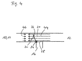
- FIG 14 shows schematically the structure of a system of State of the art.
- a vehicle heater 110 with a Air inlet 138 which is not shown in detail, is with a mixing chamber 114 in conjunction. Furthermore, one is Additional heater 112 is provided, the air inlet 136th having. The additional heater 112 is connected to the mixing chamber 114 in connection.
- the mixing chamber 114 has several Air channels 140 for the escape of air. In general exists in the mixing chamber 114, the possibility of the there entering volume flow through flaps in the different Divert air ducts 140 or air ducts 140 complete. This will give the user the option given, extensive settings for air conditioning to make the interior of a motor vehicle.
- an air flow 142 from the vehicle heater 110 and in the mixing chamber 114 a.
- an airflow 144 exits the auxiliary heater 112 from and into the mixing chamber 114 a. Because of these independent air flows 142, 144 may result in a negative feedback, the for example, to the back pressure 146 against the flow 144th the auxiliary heater 112 can lead. In Figure 14, the back pressure 146 a small amount, leaving a proper Working the heating system is possible.
- FIG. 15 shows a system which is of a construction her corresponds to that of Figure 14.
- the heating system according to FIG. 15 does not work properly. This results from the increased back pressure 146, which in the case is so large that it reverses the Air flow 144 causes.
- the additional heater has a fan. This is in Contrary to the fan of the vehicle heating relatively pressure-resistant, however, producing a lower volume flow becomes.
- the blower of the additional heating principle not independent of the heating power the additional heating are regulated. If more heating power is required, so the volume flow increases and vice versa. Due to the change in the volumetric flow of Additional heating also changes the pressure stiffness.
- the blow-out temperature at the additional heater is among other things depending on the additional heating counteracting Resistors. This can be increased at high resistance Outlet temperature caused by down regulation or switching off the auxiliary heater is limited.
- the additional heating For the operation of the additional heating, it is therefore ideal if at low outside temperatures with high heat outputs, that is, high volume flows and thus high pressure rigidity can run.
- the additional heating can then the Counteract blower of the vehicle heating, in particular if the latter is operated with low blower levels or if only a few flaps in the mixing chamber are closed.
- the invention is based on the generic heating system characterized, that at least one additional blower is provided, with the one flow in the direction of the second heater can be generated to the first heater.
- the flow or the pressure from the second heater in the direction of the vehicle heater so Far increase that the second heater under any Conditions are not overridden.
- there is no damming the flow connection between the second heater and the vehicle heating required although a stable and gentle heater operation guaranteed becomes.
- the second heater will prevent overpressing. in the second heater prevail on average lower temperatures, so that the components are less stressed. It can a uniform operation of the second heating take place, which in particular requires fewer control cycles, whereby a burner in the second heater less loaded becomes.
- the heat energy contribution of the second Heating can be increased because the maximum heating power is greater becomes. It can ensure a clean start and burnout cycle become. Since it is not necessary, the flow connection between the first heater and the second To interrupt heating, the heat energy from the second heating always optimally utilized.
- the invention develops its advantages in particular by that the first heater is a vehicle heater and that the second heater is an auxiliary heater.
- the invention is advantageous for the interaction of heaters can be used in any environment. Special advantages but arise when used in a motor vehicle. There are additional heaters often with vehicle heaters or combined with vehicle heating systems, that are already in use.
- the invention opened by the provision of stable flow conditions the additional heater to be incorporated in a vehicle system a motor vehicle the possibility of a problem-free Integration.
- At least one mixing chamber is provided, in from the at least one first heater and out of the Enter at least one second heater emitted air can.
- a mixing chamber is useful to air with a uniform temperature in the interior of the motor vehicle initiate. The connection of the vehicle heating with the additional heating is then generally about this It is also the problem of the Overpressure can come.
- a mixing chamber often flaps on, with which channels in whole or in part can be closed, so that the back pressure against the flow from the additional heating can be very high.
- auxiliary fan before the second heater is arranged. This position is too prefer, because in this way the auxiliary fan none Heat load is exposed. It is also conceivable the auxiliary fan in the area of an air intake for to lay the additional heating. However, it is also in scope the present invention, an additional blower behind to arrange the auxiliary heater. This is especially true possible if one chooses an auxiliary fan, the one higher Heat load withstands.
- the heating system according to the invention thereby developed, that the auxiliary fan in response to an output signal a control unit is actuated.
- a controller can handle numerous input data when deciding whether the auxiliary blower is to be operated, involve.
- Input signals come into direct contact with the heating system keep in touch. But there are others too Signals are utilized, for example, CAN bus signals.
- At least one pressure sensor for Generating an input signal for a controller is.
- a pressure sensor can, for example, as Differential pressure sensor designed to be the difference between the pressure in front of the auxiliary heater and the pressure in the or after the additional heater is measured. at too high a difference is most likely one Overpressure before, so that measures from the control unit can be initiated, for example, the connection the auxiliary fan.
- the Pressure difference is not always a specific feature for a damming is. It is also possible that at low pressures a damming occurs. Likewise For example, at high speeds a high pressure without Damming present.
- At least one Temperature sensor for generating an input signal for a Control unit is provided.
- the evaluation of the temperature signals can for example by a gradient evaluation respectively. For example, if a temperature sensor is nearby the output of the auxiliary heater installed, it may be at a suppression to a sudden drop in temperature come in the range of this temperature sensor. Because such a Temperature drop at a steady or rising Heating power without the presence of a suppression not could be from the temperature drop to one Suppression be closed. It is also possible several temperature sensors in the additional heating to install and out of the spatial temperature history to close any suppression.
- auxiliary fan can be regulated is.
- Such a scheme can be stepless or in stages take place, these control tasks preferably from Control unit of the additional heating are taken over. Also Is it possible to do one in stages, respectively to provide a stepless control.
- the system can be designed so that the auxiliary fan only on or off. For this purpose, for example, a relay can be used.
- auxiliary fan directly in response to an output signal of a temperature sensor is operable.
- a temperature sensor For example, may be a bimetallic element, so that a Control of the additional blower independent of a control unit can be done.
- the invention is based on the generic method thereby on that by at least one additional blower a Flow in the direction from the second heater to the first heating is generated.
- a Flow in the direction from the second heater to the first heating is generated.
- the invention develops its advantages in particular by that the first heater is a vehicle heater and that the second heater is an auxiliary heater.
- auxiliary fan it may be useful for the auxiliary fan to be regulated becomes.
- auxiliary fan it may be useful to turn on the auxiliary fan or turned off when the second heater is switched on or off.
- the auxiliary fan So it is only supportive for the fan of the second heater used and especially only during the Heating operation of the second heater.
- auxiliary fan is switched on or off when the first heating is switched on. Because the danger of being overpowered of the heating system during the switch-on of the first heating system can be such an operating mode make the additional fan sense.
- the auxiliary fan is turned on, if a suppression of the heating system detected becomes. In this way, the operating time of the additional blower minimized, since it is only switched on, if the condition is present for which the heating system with auxiliary blower is designed.
- the invention is based on the generic air heater in that when a limit value is exceeded by a temperature-dependent size of the burner in one Condition is transferred with lower heating power.
- This is the normal mode for determining the Air inlet temperature used temperature sensor in the air inlet area of the air heater used to a Recirculation of heated air to determine. this happens on the determination of a temperature-dependent variable. If this temperature-dependent size a certain Exceeds limit, countermeasures can be taken in particular, the burner in a state is transferred with lower heating power. Consequently, will unwanted overheating of electronic components, for example, in the area of the control unit, counteracted.
- the air heater according to the invention in the way that when crossing a Limit value by a temperature-dependent size of the burner is switched off. Consequently, a further warming of heating air is reduced to a minimum, creating a particularly effective countermeasure provided becomes.
- Cooling caster causes that possibly already in one critical temperature state components quickly can be cooled down again, so that afterwards in a normal burner operation can be passed.
- the invention further consists in a method for detecting returning hot air through an air heater, at the temperature in an air inlet area means a temperature sensor arranged in the air inlet region is monitored and when a limit value is exceeded by a temperature dependent size of the burner of the Air heater in a state with lower heat output is transferred. That way they are related described with the air heater according to the invention Advantages also implemented in the context of a procedure. This also applies to the following advantageous Embodiments of the method according to the invention for Recognizing backflowing heating air.
- the method according to the invention can be characterized in particular be designed advantageously that additionally or alternatively for gradient evaluation as temperature-dependent Size the temperature itself is used, so that when Exceeding a maximum temperature of the burner switched off becomes.
- a Exhaust opening 16 is provided in the connection area between additional heating 12 and mixing chamber 14, which is also the connection area between auxiliary heater 12 and vehicle heater 10.
- a switching flap 18 is articulated in the area of this exhaust air opening 16.
- FIG. 3 shows a perspective view of the second one Embodiment of a changeover door 20.
- the Umschaltklappe 20 can be seen. Make up the first region 26 and the second region 28 in cross section an L-shaped structure, that of the first Area 26 and the second area 28 included angle greater than 90 °. The first area 26 continues an opening 30. This opening can from the cover 32nd be released or closed. by virtue of the forces, the fluid mechanical on the Umschaltklappe Act 20, the changeover 20 can by articulated storage to be pivoted about the axis 34.
- FIG. 5 shows a schematic representation of a part of a Heating system with a second embodiment of a changeover 20 during a second flow state.
- This flow condition is achieved when the back pressure 46, from the direction of the vehicle heater 10 respectively the mixing chamber 14 comes, rises. Is this the Case, then closes the check valve 20 in increasing Dimensions. Will the back pressure 46 so strong that the flow 44 of the auxiliary heater 12 is no longer in the right place Direction can be done, then the check valve 20 completely closed. The build-up dynamic pressure forces the changeover door 20 to tip over. Also closes acting as a non-return flap cover 32, the opening (30, Figure 3) of the first portion 26 of the changeover 20. When the pressure 46 of the vehicle heater 10 decreases, so is through the flow 44 and through this resulting overpressure on the non-return valve 20 forced them to tip over in the other direction again.
- FIGS. 1, 2, 4 and 5 show the switching flaps 18, 20 always in the connecting region between the mixing chamber 14 and the auxiliary heater 12. This is a preferred position of Switching flaps 18, 20. However, there are also other positions possible, for example, directly at the outlet of the auxiliary heater 12 or in the range of mixing chamber 14 or Vehicle heating 10.
- auxiliary heater 12 It can be a smoother Operation of the auxiliary heater 12 take place, in particular requires less control cycles, reducing the burner is charged less in the auxiliary heater 12.
- the heat energy contribution the auxiliary heater 12 can be increased because the maximum heating power is greater. Furthermore, a ensure a clean start and burnout cycle. There no damming and therefore no exhaust port must be provided, less heat energy is lost.
- the additional blower 50 only with a switch-on or Off function to provide. This makes possible a particularly simple control, for example via a relay. But it is also possible, the additional fan 50th steplessly regulate or control. This can be done directly from Heating control unit are made. Also in the case of one On-off control, that means without speed change, For example, the heater controller may issue a triggering signal to generate. It is also possible to over this signal an additional temperature sensor, for example a Bimetal element, regardless of the heater control unit to make.
- Interventions in the operation of the additional blower 50 can under different conditions take place.
- the auxiliary fan For example, it can always be turned on when turns on the heater. In another case that can Switching on the additional blower 50 by switching on the vehicle heating 10 are made dependent. Also can be provided be that just in case of overpowering or Damming the auxiliary fan is switched on.
- FIG. 6 the position of the auxiliary blower 50 is in front of Additional heater 12 shown. This position is to be preferred because in this way the auxiliary fan 50 no heat load is suspended. It is also conceivable that Additional blower 50 in the region of the air inlet 36 to embarrassed. If one chooses an additional blower 50, which is a certain Heat load can withstand, so it is also possible the auxiliary fan 50 behind the auxiliary heater 12, that is between additional heater 12 and mixing chamber 14, to order.
- FIG. 7 shows a diagram in which pressure differences of Press in front of and behind an additional air heater or a vehicle heating applied against the flow are.
- the blower characteristics shown are partial only qualitatively.
- Curve a shows the characteristic curve a blower of a vehicle heater on a high level.
- Curve b shows the characteristic of a comparatively small one Blower of an additional heater at a relatively low speed;
- Curve c shows the characteristic of the same blower at elevated Rotation speed.
- Curve d shows the characteristic curve of a larger blower at a relatively low speed;
- Curve e shows the characteristic curve the same fan at increased speed.
- FIG. 8 shows a schematic representation of a heating system with a non-return valve.
- the illustrated heating system corresponds in many parts to the heating system of the state the technique according to Figures 14 and 15 and the Heating systems, in connection with the figures 1 to 6 were explained.
- additional components are one Non-return valve 56 between the auxiliary heater 12 and the Mixing chamber 14 and the vehicle heater 10 and an additional temperature sensor 58 at the entrance of the Additional heater 12 is provided.
- the additional temperature sensor 58 can directly on the control unit of the auxiliary air heater 12 be attached.
- the sensor should be free in the Air flow, so as to the lowest possible inertia realize.
- the connections and a possibly provided However, plugs on the temperature sensor should be waterproof be.
- the auxiliary heater 12 In the area of the temperature sensor 58 at the entrance of the auxiliary heater 12, however, is the returning air through the auxiliary heater 12 sufficient be heated, so that the temperature rise as reliable Indication of overpressing can be used.
- the auxiliary heater 12 is of a in itself low value, preferably to 100%.
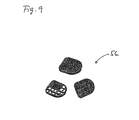
- Figure 9 shows three perspective views of a Check valve in different perspectives respectively States of assembly.
- check valves 56 these have in common that a grid-shaped carrier with one or more on top arranged elastic tabs is provided. The rags can completely cover the grid-shaped carrier.
- FIG. 10 shows a schematic representation of an additional air heater 12 with a pressure difference sensor 22. It is furthermore a control unit 60, a blower 62 and a heat exchanger 70 is shown. On the control unit 60 is a Pressure differential sensor 22 attached, which via a pressure line 64 with the area in front of the auxiliary air heater 12, the is the inflow area connected. The pressure difference sensor 22 is thus able to make a difference of one Pressure 66 in front and a pressure 68 behind the auxiliary air heating 12 to measure. This signal can then be sent directly to the controller 60 are entered. Will too much pressure difference determined, so will depending on the embodiment of the remaining heating system on a suppression or a confinement closed. The auxiliary heater 12 is then switched off or in another operating mode transferred.
- a wind direction sensor or a Flow sensor to use. This one is able to detect a flow direction using methods Can be on an impeller, a calorimetric Determination by a heating wire or by ultrasound based. Furthermore, the speed change of a Blowers are used as evidence of overpowering, as the speed increases as soon as the heater is blocked or is suppressed. This increase in Blower speed can be detected by the heater control unit 60 and evaluated.
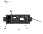
- FIG. 11 shows a schematic representation of an additional air heater 12 with a plurality of temperature sensors 24, wherein otherwise a similar structure as in Figure 10 are recognized can. These temperature sensors 24 are at different Positions of the auxiliary air heater 12 is arranged.
- the Information of the different temperature sensors 24 can be used in different ways. There is for example, operating conditions in which case in case of Suppression the temperature of the temperature sensor 24 in the area of the control unit 60 and the middle temperature sensor 24 rise while the temperature of the temperature sensor 24 in the area of the output of the additional heating 12 drops. This condition can be used, for example, as an indication be used for a suppression. Likewise the temporal change of the temperature at the temperature sensors be used in a gradient evaluation.
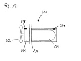
- FIG. 12 shows a schematic representation of a device according to the invention Air heater 210.
- the air heater 210 includes a heat exchanger 270 and one in the region of Heat exchanger 270 arranged temperature sensor 224th This temperature sensor 224 is within the scope of a conventional Overheating protection of the air heater 210 is used.
- a (not shown) burner provided within the heat exchanger 270 .
- this includes Air heater 210, a control unit 260 and a Schubuch devisr or a blower 262 for introducing air to be heated in the air heater 210.
- another temperature sensor 258 is provided, generally in the context of a temperature determination the air entering the air heater 210 is used. On the basis of this temperature determination of the incoming Air can optimize the operation of the air heater 210 become.
- the invention uses that of the temperature sensor 258 captures temperature information to such a situation too avoid.
- the temporal temperature increase in the area of the temperature sensor 258 in the control unit 260 are monitored.
- the measure of the burner in transfers an operating condition with lower heating power; the burner is switched off, for example. optional a cooling lag can be carried out.
- the by the flow reversal induced situation then Take into account when the temperature of the temperature sensor 258 exceeds a certain absolute limit.
- FIG. 13 shows a flow chart for explaining a method according to the invention for detecting backflowing heating air through an air heater.
- a control operation of the control unit is determined in the context of the inventive method, whether the temporal temperature gradient d ⁇ / dt is greater than a maximum temperature gradient (d ⁇ / dt) MAX . If this is the case, the heater can be switched off, for example. In the other case, a further check can be made; it is checked whether the absolute temperature u is greater than a maximum temperature ⁇ MAX . If this is the case, this can also be used as a criterion for switching off the heater, for example. If not, then the normal control operation is transferred, which also means that subsequently again the already described inventive review takes place.
Priority Applications (1)
| Application Number | Priority Date | Filing Date | Title |
|---|---|---|---|
| EP06014057A EP1702774A1 (fr) | 2001-06-18 | 2002-05-10 | Système de chauffage et procédé pour influencer les courants d'air dans un système de chauffage |
Applications Claiming Priority (5)
| Application Number | Priority Date | Filing Date | Title |
|---|---|---|---|
| DE10129205 | 2001-06-18 | ||
| DE10129205 | 2001-06-18 | ||
| DE10209519 | 2002-03-04 | ||
| DE10209519A DE10209519B4 (de) | 2001-06-18 | 2002-03-04 | Heizsystem und Verfahren zum Beeinflussen von Luftströmungen in einem Heizsystem |
| EP02010602A EP1270289B1 (fr) | 2001-06-18 | 2002-05-10 | Système de chauffage et procédé pour la détection du reflux d'air chaud |
Related Parent Applications (1)
| Application Number | Title | Priority Date | Filing Date |
|---|---|---|---|
| EP02010602A Division EP1270289B1 (fr) | 2001-06-18 | 2002-05-10 | Système de chauffage et procédé pour la détection du reflux d'air chaud |
Related Child Applications (1)
| Application Number | Title | Priority Date | Filing Date |
|---|---|---|---|
| EP06014057A Division EP1702774A1 (fr) | 2001-06-18 | 2002-05-10 | Système de chauffage et procédé pour influencer les courants d'air dans un système de chauffage |
Publications (2)
| Publication Number | Publication Date |
|---|---|
| EP1533156A1 true EP1533156A1 (fr) | 2005-05-25 |
| EP1533156B1 EP1533156B1 (fr) | 2007-04-04 |
Family
ID=7688497
Family Applications (2)
| Application Number | Title | Priority Date | Filing Date |
|---|---|---|---|
| EP06014057A Withdrawn EP1702774A1 (fr) | 2001-06-18 | 2002-05-10 | Système de chauffage et procédé pour influencer les courants d'air dans un système de chauffage |
| EP05003293A Expired - Lifetime EP1533156B1 (fr) | 2001-06-18 | 2002-05-10 | Système de chauffage et procédé pour influencer les courants d'air dans un système de chauffage |
Family Applications Before (1)
| Application Number | Title | Priority Date | Filing Date |
|---|---|---|---|
| EP06014057A Withdrawn EP1702774A1 (fr) | 2001-06-18 | 2002-05-10 | Système de chauffage et procédé pour influencer les courants d'air dans un système de chauffage |
Country Status (2)
| Country | Link |
|---|---|
| EP (2) | EP1702774A1 (fr) |
| DE (1) | DE10209519B4 (fr) |
Cited By (1)
| Publication number | Priority date | Publication date | Assignee | Title |
|---|---|---|---|---|
| CN106627035A (zh) * | 2016-11-25 | 2017-05-10 | 三汽车制造有限公司 | 驾驶室暖风装置、暖风系统及驾驶室和工程机械 |
Families Citing this family (2)
| Publication number | Priority date | Publication date | Assignee | Title |
|---|---|---|---|---|
| DE102010030663B4 (de) * | 2010-06-29 | 2021-05-12 | Eberspächer Climate Control Systems GmbH | Verfahren zum Betreiben eines Fahrzeugtemperiergeräts |
| DE102016123537B3 (de) | 2016-12-06 | 2018-03-01 | Eberspächer Climate Control Systems GmbH & Co. KG | Verfahren zum Betreiben eines brennstoffbetriebenen Fahrzeugheizgerätes |
Citations (5)
| Publication number | Priority date | Publication date | Assignee | Title |
|---|---|---|---|---|
| US4205944A (en) * | 1973-08-16 | 1980-06-03 | Suddeutsche Kuhlerfabrick Julius Fr. Behr | Electronic control circuit for blowers in vehicles |
| JPS61263823A (ja) * | 1985-05-20 | 1986-11-21 | Nippon Denso Co Ltd | 車両用暖房装置 |
| EP0235464A1 (fr) * | 1985-12-28 | 1987-09-09 | Isuzu Motors Limited | Dispositif de chauffage pour réservoir |
| US4726514A (en) * | 1985-05-18 | 1988-02-23 | Webasto-Werk W. Baier Gmbh & Co. | Heating device |
| JPS63141818A (ja) * | 1986-12-04 | 1988-06-14 | Nippon Denso Co Ltd | 車両用暖房装置 |
Family Cites Families (9)
| Publication number | Priority date | Publication date | Assignee | Title |
|---|---|---|---|---|
| DE1991365U (de) * | 1968-08-08 | Stewart-Warner Corporation, Chicago, Ill. (V.St.A.) | Kraftfahrzeug mit Heizvorrichtung für den Fahrgastraum | |
| US4625911A (en) * | 1984-05-18 | 1986-12-02 | Diesel Kiki Co., Ltd. | Air conditioner system for automobiles |
| JPS60259521A (ja) * | 1984-06-04 | 1985-12-21 | Nippon Denso Co Ltd | 車両用暖房装置 |
| JPH07115582B2 (ja) * | 1986-11-13 | 1995-12-13 | いすゞ自動車株式会社 | 車両用暖房装置 |
| FR2686837B1 (fr) * | 1992-01-31 | 1995-05-24 | Valeo Thermique Habitacle | Dispositif de chauffage-ventilation de l'habitacle d'un vehicule automobile a moteur a faibles rejets thermiques. |
| CN1139407A (zh) * | 1993-12-31 | 1997-01-01 | J.埃伯斯帕彻公司 | 具有过热监控装置的汽车加热装置 |
| DE19524260C5 (de) * | 1995-07-04 | 2005-11-17 | J. Eberspächer GmbH & Co. KG | Heizgerät, insbesondere zur Innenraumbeheizung eines Kraftfahrzeuges |
| DE19802906A1 (de) * | 1998-01-27 | 1999-07-29 | Eberspaecher J Gmbh & Co | Brennstoffbetriebenes Luftheizgerät |
| US6089221A (en) * | 1998-07-06 | 2000-07-18 | Rinnai Kabushiki Kaisha | Space heater |
-
2002
- 2002-03-04 DE DE10209519A patent/DE10209519B4/de not_active Expired - Fee Related
- 2002-05-10 EP EP06014057A patent/EP1702774A1/fr not_active Withdrawn
- 2002-05-10 EP EP05003293A patent/EP1533156B1/fr not_active Expired - Lifetime
Patent Citations (5)
| Publication number | Priority date | Publication date | Assignee | Title |
|---|---|---|---|---|
| US4205944A (en) * | 1973-08-16 | 1980-06-03 | Suddeutsche Kuhlerfabrick Julius Fr. Behr | Electronic control circuit for blowers in vehicles |
| US4726514A (en) * | 1985-05-18 | 1988-02-23 | Webasto-Werk W. Baier Gmbh & Co. | Heating device |
| JPS61263823A (ja) * | 1985-05-20 | 1986-11-21 | Nippon Denso Co Ltd | 車両用暖房装置 |
| EP0235464A1 (fr) * | 1985-12-28 | 1987-09-09 | Isuzu Motors Limited | Dispositif de chauffage pour réservoir |
| JPS63141818A (ja) * | 1986-12-04 | 1988-06-14 | Nippon Denso Co Ltd | 車両用暖房装置 |
Non-Patent Citations (2)
| Title |
|---|
| PATENT ABSTRACTS OF JAPAN vol. 011, no. 123 (M - 581) 17 April 1987 (1987-04-17) * |
| PATENT ABSTRACTS OF JAPAN vol. 012, no. 392 (M - 755) 19 October 1988 (1988-10-19) * |
Cited By (2)
| Publication number | Priority date | Publication date | Assignee | Title |
|---|---|---|---|---|
| CN106627035A (zh) * | 2016-11-25 | 2017-05-10 | 三汽车制造有限公司 | 驾驶室暖风装置、暖风系统及驾驶室和工程机械 |
| CN106627035B (zh) * | 2016-11-25 | 2023-07-07 | 三一汽车制造有限公司 | 驾驶室暖风装置、暖风系统及驾驶室和工程机械 |
Also Published As
| Publication number | Publication date |
|---|---|
| DE10209519B4 (de) | 2007-04-05 |
| EP1533156B1 (fr) | 2007-04-04 |
| EP1702774A1 (fr) | 2006-09-20 |
| DE10209519A1 (de) | 2003-01-02 |
Similar Documents
| Publication | Publication Date | Title |
|---|---|---|
| DE102011015260B4 (de) | Antriebsstrang-Wärmeregelung mittels Kühlergrill-Luftstromverschlussklappen | |
| DE10220168B4 (de) | Fahrzeugklimaanlage und Regelungsverfahren einer solchen | |
| DE69630665T2 (de) | Fahrzeugklimaanlage | |
| EP1526974B1 (fr) | Installation de climatisation pour vehicule automobile | |
| DE69926094T2 (de) | Steuerung für Klimaanlage | |
| DE112016000555B4 (de) | Klimatisierungsgerät | |
| DE112016002423B4 (de) | Fahrzeugklimaanlage | |
| EP2732090B1 (fr) | Sèche-linge à évacuation doté d'un chauffage additionnel et ensemble échangeur de chaleur | |
| DE4410249A1 (de) | Flüssigkeitskühlkreislauf für Verbrennungsmotoren | |
| DE112013000861T5 (de) | Fahrzeugklimaanlage | |
| DE112017006613T5 (de) | Steuermodul | |
| DE69935923T2 (de) | Kühlungsregler für eine brennkraftmaschine | |
| DE10224728A1 (de) | Motorkühlsystem | |
| EP2636959B1 (fr) | Réglage de radiateur | |
| DE112011102776B4 (de) | Verfahren zur Ermittlung einer Temperatur einer Reibungskupplung | |
| DE19500648B4 (de) | Kühlanlage für einen Verbrennungsmotor eines Kraftfahrzeuges mit einem Thermostatventil | |
| EP1270289B1 (fr) | Système de chauffage et procédé pour la détection du reflux d'air chaud | |
| EP1533156A1 (fr) | Système de chauffage et procédé pour influencer les courants d'air dans un système de chauffage | |
| DE102014108118B3 (de) | Wohnraumlüftungssystem mit Heizungsfunktion | |
| EP1270290B1 (fr) | Système de chauffage et procédé pour influencer les courants d'air dans un système de chauffage | |
| DE10138821B4 (de) | Verfahren zum Ermitteln einer Heizluft-Ausblastemperatur eines Luftheizgerätes | |
| DE10129206A1 (de) | Heizsystem, Verfahren zum Beeinflussen von Luftströmungen in einem Heizsystem und strömungsmechanisches System | |
| WO2017182326A1 (fr) | Dispositif et procédé destinés à régler la température dans une pièce, notamment dans un habitacle | |
| EP4034395B1 (fr) | Procédé de climatisation | |
| EP2036747A1 (fr) | Chauffage pour une voiture |
Legal Events
| Date | Code | Title | Description |
|---|---|---|---|
| PUAI | Public reference made under article 153(3) epc to a published international application that has entered the european phase |
Free format text: ORIGINAL CODE: 0009012 |
|
| 17P | Request for examination filed |
Effective date: 20050216 |
|
| AC | Divisional application: reference to earlier application |
Ref document number: 1270289 Country of ref document: EP Kind code of ref document: P |
|
| AK | Designated contracting states |
Kind code of ref document: A1 Designated state(s): AT BE CH CY DE DK ES FI FR GB GR IE IT LI LU MC NL PT SE TR |
|
| AX | Request for extension of the european patent |
Extension state: AL LT LV MK RO SI |
|
| RIN1 | Information on inventor provided before grant (corrected) |
Inventor name: GERHARDT, NIKOLAUS Inventor name: MAY, ANDREAS Inventor name: WIDEMANN, FRIEDRICH Inventor name: LUDWIG, ANDREAS Inventor name: ELM, NILS |
|
| AKX | Designation fees paid |
Designated state(s): AT BE CH CY DE DK ES FI FR GB GR IE IT LI LU MC NL PT SE TR |
|
| RIN1 | Information on inventor provided before grant (corrected) |
Inventor name: WIDEMANN, FRIEDRICH Inventor name: MAY, ANDREAS Inventor name: GERHARDT, NIKOLAUS Inventor name: ELM, NILS Inventor name: LUDWIG, ANDREAS |
|
| GRAP | Despatch of communication of intention to grant a patent |
Free format text: ORIGINAL CODE: EPIDOSNIGR1 |
|
| GRAS | Grant fee paid |
Free format text: ORIGINAL CODE: EPIDOSNIGR3 |
|
| GRAA | (expected) grant |
Free format text: ORIGINAL CODE: 0009210 |
|
| AC | Divisional application: reference to earlier application |
Ref document number: 1270289 Country of ref document: EP Kind code of ref document: P |
|
| AK | Designated contracting states |
Kind code of ref document: B1 Designated state(s): AT BE CH CY DE DK ES FI FR GB GR IE IT LI LU MC NL PT SE TR |
|
| PG25 | Lapsed in a contracting state [announced via postgrant information from national office to epo] |
Ref country code: FI Free format text: LAPSE BECAUSE OF FAILURE TO SUBMIT A TRANSLATION OF THE DESCRIPTION OR TO PAY THE FEE WITHIN THE PRESCRIBED TIME-LIMIT Effective date: 20070404 |
|
| REG | Reference to a national code |
Ref country code: GB Ref legal event code: FG4D Free format text: NOT ENGLISH |
|
| REG | Reference to a national code |
Ref country code: CH Ref legal event code: EP |
|
| REF | Corresponds to: |
Ref document number: 50209885 Country of ref document: DE Date of ref document: 20070516 Kind code of ref document: P |
|
| REG | Reference to a national code |
Ref country code: IE Ref legal event code: FG4D Free format text: LANGUAGE OF EP DOCUMENT: GERMAN |
|
| PG25 | Lapsed in a contracting state [announced via postgrant information from national office to epo] |
Ref country code: SE Free format text: LAPSE BECAUSE OF FAILURE TO SUBMIT A TRANSLATION OF THE DESCRIPTION OR TO PAY THE FEE WITHIN THE PRESCRIBED TIME-LIMIT Effective date: 20070704 |
|
| PG25 | Lapsed in a contracting state [announced via postgrant information from national office to epo] |
Ref country code: ES Free format text: LAPSE BECAUSE OF FAILURE TO SUBMIT A TRANSLATION OF THE DESCRIPTION OR TO PAY THE FEE WITHIN THE PRESCRIBED TIME-LIMIT Effective date: 20070715 |
|
| PG25 | Lapsed in a contracting state [announced via postgrant information from national office to epo] |
Ref country code: PT Free format text: LAPSE BECAUSE OF FAILURE TO SUBMIT A TRANSLATION OF THE DESCRIPTION OR TO PAY THE FEE WITHIN THE PRESCRIBED TIME-LIMIT Effective date: 20070904 |
|
| NLV1 | Nl: lapsed or annulled due to failure to fulfill the requirements of art. 29p and 29m of the patents act | ||
| GBV | Gb: ep patent (uk) treated as always having been void in accordance with gb section 77(7)/1977 [no translation filed] |
Effective date: 20070404 |
|
| REG | Reference to a national code |
Ref country code: IE Ref legal event code: FD4D |
|
| EN | Fr: translation not filed | ||
| BERE | Be: lapsed |
Owner name: WEBASTO A.G. Effective date: 20070531 |
|
| REG | Reference to a national code |
Ref country code: CH Ref legal event code: PL |
|
| PG25 | Lapsed in a contracting state [announced via postgrant information from national office to epo] |
Ref country code: IE Free format text: LAPSE BECAUSE OF FAILURE TO SUBMIT A TRANSLATION OF THE DESCRIPTION OR TO PAY THE FEE WITHIN THE PRESCRIBED TIME-LIMIT Effective date: 20070404 Ref country code: MC Free format text: LAPSE BECAUSE OF NON-PAYMENT OF DUE FEES Effective date: 20070531 Ref country code: DK Free format text: LAPSE BECAUSE OF FAILURE TO SUBMIT A TRANSLATION OF THE DESCRIPTION OR TO PAY THE FEE WITHIN THE PRESCRIBED TIME-LIMIT Effective date: 20070404 Ref country code: NL Free format text: LAPSE BECAUSE OF FAILURE TO SUBMIT A TRANSLATION OF THE DESCRIPTION OR TO PAY THE FEE WITHIN THE PRESCRIBED TIME-LIMIT Effective date: 20070404 |
|
| PLBE | No opposition filed within time limit |
Free format text: ORIGINAL CODE: 0009261 |
|
| STAA | Information on the status of an ep patent application or granted ep patent |
Free format text: STATUS: NO OPPOSITION FILED WITHIN TIME LIMIT |
|
| PG25 | Lapsed in a contracting state [announced via postgrant information from national office to epo] |
Ref country code: CH Free format text: LAPSE BECAUSE OF NON-PAYMENT OF DUE FEES Effective date: 20070531 Ref country code: LI Free format text: LAPSE BECAUSE OF NON-PAYMENT OF DUE FEES Effective date: 20070531 |
|
| 26N | No opposition filed |
Effective date: 20080107 |
|
| PG25 | Lapsed in a contracting state [announced via postgrant information from national office to epo] |
Ref country code: BE Free format text: LAPSE BECAUSE OF NON-PAYMENT OF DUE FEES Effective date: 20070531 |
|
| PG25 | Lapsed in a contracting state [announced via postgrant information from national office to epo] |
Ref country code: FR Free format text: LAPSE BECAUSE OF FAILURE TO SUBMIT A TRANSLATION OF THE DESCRIPTION OR TO PAY THE FEE WITHIN THE PRESCRIBED TIME-LIMIT Effective date: 20071130 Ref country code: GR Free format text: LAPSE BECAUSE OF FAILURE TO SUBMIT A TRANSLATION OF THE DESCRIPTION OR TO PAY THE FEE WITHIN THE PRESCRIBED TIME-LIMIT Effective date: 20070705 Ref country code: IT Free format text: LAPSE BECAUSE OF FAILURE TO SUBMIT A TRANSLATION OF THE DESCRIPTION OR TO PAY THE FEE WITHIN THE PRESCRIBED TIME-LIMIT Effective date: 20070404 Ref country code: GB Free format text: LAPSE BECAUSE OF FAILURE TO SUBMIT A TRANSLATION OF THE DESCRIPTION OR TO PAY THE FEE WITHIN THE PRESCRIBED TIME-LIMIT Effective date: 20070404 Ref country code: DE Free format text: LAPSE BECAUSE OF NON-PAYMENT OF DUE FEES Effective date: 20071201 |
|
| PG25 | Lapsed in a contracting state [announced via postgrant information from national office to epo] |
Ref country code: AT Free format text: LAPSE BECAUSE OF NON-PAYMENT OF DUE FEES Effective date: 20070510 |
|
| PG25 | Lapsed in a contracting state [announced via postgrant information from national office to epo] |
Ref country code: FR Free format text: LAPSE BECAUSE OF FAILURE TO SUBMIT A TRANSLATION OF THE DESCRIPTION OR TO PAY THE FEE WITHIN THE PRESCRIBED TIME-LIMIT Effective date: 20070404 |
|
| PG25 | Lapsed in a contracting state [announced via postgrant information from national office to epo] |
Ref country code: CY Free format text: LAPSE BECAUSE OF FAILURE TO SUBMIT A TRANSLATION OF THE DESCRIPTION OR TO PAY THE FEE WITHIN THE PRESCRIBED TIME-LIMIT Effective date: 20070404 |
|
| PG25 | Lapsed in a contracting state [announced via postgrant information from national office to epo] |
Ref country code: LU Free format text: LAPSE BECAUSE OF NON-PAYMENT OF DUE FEES Effective date: 20070510 |
|
| PG25 | Lapsed in a contracting state [announced via postgrant information from national office to epo] |
Ref country code: TR Free format text: LAPSE BECAUSE OF FAILURE TO SUBMIT A TRANSLATION OF THE DESCRIPTION OR TO PAY THE FEE WITHIN THE PRESCRIBED TIME-LIMIT Effective date: 20070404 |