EP1533156A1 - Heating system and method for influencing air flows in a heating system - Google Patents
Heating system and method for influencing air flows in a heating system Download PDFInfo
- Publication number
- EP1533156A1 EP1533156A1 EP05003293A EP05003293A EP1533156A1 EP 1533156 A1 EP1533156 A1 EP 1533156A1 EP 05003293 A EP05003293 A EP 05003293A EP 05003293 A EP05003293 A EP 05003293A EP 1533156 A1 EP1533156 A1 EP 1533156A1
- Authority
- EP
- European Patent Office
- Prior art keywords
- heater
- heating
- heating system
- air
- additional
- Prior art date
- Legal status (The legal status is an assumption and is not a legal conclusion. Google has not performed a legal analysis and makes no representation as to the accuracy of the status listed.)
- Granted
Links
Images


Classifications
-
- B—PERFORMING OPERATIONS; TRANSPORTING
- B60—VEHICLES IN GENERAL
- B60H—ARRANGEMENTS OF HEATING, COOLING, VENTILATING OR OTHER AIR-TREATING DEVICES SPECIALLY ADAPTED FOR PASSENGER OR GOODS SPACES OF VEHICLES
- B60H1/00—Heating, cooling or ventilating [HVAC] devices
- B60H1/22—Heating, cooling or ventilating [HVAC] devices the heat being derived otherwise than from the propulsion plant
- B60H1/2203—Heating, cooling or ventilating [HVAC] devices the heat being derived otherwise than from the propulsion plant the heat being derived from burners
- B60H1/2212—Heating, cooling or ventilating [HVAC] devices the heat being derived otherwise than from the propulsion plant the heat being derived from burners arrangements of burners for heating air
-
- B—PERFORMING OPERATIONS; TRANSPORTING
- B60—VEHICLES IN GENERAL
- B60H—ARRANGEMENTS OF HEATING, COOLING, VENTILATING OR OTHER AIR-TREATING DEVICES SPECIALLY ADAPTED FOR PASSENGER OR GOODS SPACES OF VEHICLES
- B60H1/00—Heating, cooling or ventilating [HVAC] devices
- B60H1/02—Heating, cooling or ventilating [HVAC] devices the heat being derived from the propulsion plant
- B60H1/03—Heating, cooling or ventilating [HVAC] devices the heat being derived from the propulsion plant and from a source other than the propulsion plant
- B60H1/032—Heating, cooling or ventilating [HVAC] devices the heat being derived from the propulsion plant and from a source other than the propulsion plant from the cooling liquid of the propulsion plant and from a burner
-
- B—PERFORMING OPERATIONS; TRANSPORTING
- B60—VEHICLES IN GENERAL
- B60H—ARRANGEMENTS OF HEATING, COOLING, VENTILATING OR OTHER AIR-TREATING DEVICES SPECIALLY ADAPTED FOR PASSENGER OR GOODS SPACES OF VEHICLES
- B60H1/00—Heating, cooling or ventilating [HVAC] devices
- B60H1/22—Heating, cooling or ventilating [HVAC] devices the heat being derived otherwise than from the propulsion plant
- B60H2001/2228—Heating, cooling or ventilating [HVAC] devices the heat being derived otherwise than from the propulsion plant controlling the operation of heaters
- B60H2001/224—Heating, cooling or ventilating [HVAC] devices the heat being derived otherwise than from the propulsion plant controlling the operation of heaters automatic operation, e.g. control circuits or methods
-
- B—PERFORMING OPERATIONS; TRANSPORTING
- B60—VEHICLES IN GENERAL
- B60H—ARRANGEMENTS OF HEATING, COOLING, VENTILATING OR OTHER AIR-TREATING DEVICES SPECIALLY ADAPTED FOR PASSENGER OR GOODS SPACES OF VEHICLES
- B60H1/00—Heating, cooling or ventilating [HVAC] devices
- B60H1/22—Heating, cooling or ventilating [HVAC] devices the heat being derived otherwise than from the propulsion plant
- B60H2001/2268—Constructional features
- B60H2001/2287—Integration into a vehicle HVAC system or vehicle dashboard
Definitions
- the invention relates to a heating system for heating Air, in particular for heating the interior of a motor vehicle, with at least one first heater, at least a second heater and at least one flow path between the first heater and the second heater.
- the invention further relates to a method for influencing of air flows in a heating system for heating Air, in particular for heating the interior of a motor vehicle, with at least one first heater, at least a second heater and at least one flow path between the first heater and the second heater.
- the Invention further relates to an air heater with a burner, a heat exchanger, an air inlet area, a Air outlet area, a control unit and an im Air inlet region arranged temperature sensor, wherein the temperature in the air inlet area by means of the in the air inlet area monitored temperature sensor monitors becomes.
- the invention also relates to a method for Detection of backflowing heating air through an air heater.
- FIG 14 shows schematically the structure of a system of State of the art.
- a vehicle heater 110 with a Air inlet 138 which is not shown in detail, is with a mixing chamber 114 in conjunction. Furthermore, one is Additional heater 112 is provided, the air inlet 136th having. The additional heater 112 is connected to the mixing chamber 114 in connection.
- the mixing chamber 114 has several Air channels 140 for the escape of air. In general exists in the mixing chamber 114, the possibility of the there entering volume flow through flaps in the different Divert air ducts 140 or air ducts 140 complete. This will give the user the option given, extensive settings for air conditioning to make the interior of a motor vehicle.
- an air flow 142 from the vehicle heater 110 and in the mixing chamber 114 a.
- an airflow 144 exits the auxiliary heater 112 from and into the mixing chamber 114 a. Because of these independent air flows 142, 144 may result in a negative feedback, the for example, to the back pressure 146 against the flow 144th the auxiliary heater 112 can lead. In Figure 14, the back pressure 146 a small amount, leaving a proper Working the heating system is possible.
- FIG. 15 shows a system which is of a construction her corresponds to that of Figure 14.
- the heating system according to FIG. 15 does not work properly. This results from the increased back pressure 146, which in the case is so large that it reverses the Air flow 144 causes.
- the additional heater has a fan. This is in Contrary to the fan of the vehicle heating relatively pressure-resistant, however, producing a lower volume flow becomes.
- the blower of the additional heating principle not independent of the heating power the additional heating are regulated. If more heating power is required, so the volume flow increases and vice versa. Due to the change in the volumetric flow of Additional heating also changes the pressure stiffness.
- the blow-out temperature at the additional heater is among other things depending on the additional heating counteracting Resistors. This can be increased at high resistance Outlet temperature caused by down regulation or switching off the auxiliary heater is limited.
- the additional heating For the operation of the additional heating, it is therefore ideal if at low outside temperatures with high heat outputs, that is, high volume flows and thus high pressure rigidity can run.
- the additional heating can then the Counteract blower of the vehicle heating, in particular if the latter is operated with low blower levels or if only a few flaps in the mixing chamber are closed.
- the invention is based on the generic heating system characterized, that at least one additional blower is provided, with the one flow in the direction of the second heater can be generated to the first heater.
- the flow or the pressure from the second heater in the direction of the vehicle heater so Far increase that the second heater under any Conditions are not overridden.
- there is no damming the flow connection between the second heater and the vehicle heating required although a stable and gentle heater operation guaranteed becomes.
- the second heater will prevent overpressing. in the second heater prevail on average lower temperatures, so that the components are less stressed. It can a uniform operation of the second heating take place, which in particular requires fewer control cycles, whereby a burner in the second heater less loaded becomes.
- the heat energy contribution of the second Heating can be increased because the maximum heating power is greater becomes. It can ensure a clean start and burnout cycle become. Since it is not necessary, the flow connection between the first heater and the second To interrupt heating, the heat energy from the second heating always optimally utilized.
- the invention develops its advantages in particular by that the first heater is a vehicle heater and that the second heater is an auxiliary heater.
- the invention is advantageous for the interaction of heaters can be used in any environment. Special advantages but arise when used in a motor vehicle. There are additional heaters often with vehicle heaters or combined with vehicle heating systems, that are already in use.
- the invention opened by the provision of stable flow conditions the additional heater to be incorporated in a vehicle system a motor vehicle the possibility of a problem-free Integration.
- At least one mixing chamber is provided, in from the at least one first heater and out of the Enter at least one second heater emitted air can.
- a mixing chamber is useful to air with a uniform temperature in the interior of the motor vehicle initiate. The connection of the vehicle heating with the additional heating is then generally about this It is also the problem of the Overpressure can come.
- a mixing chamber often flaps on, with which channels in whole or in part can be closed, so that the back pressure against the flow from the additional heating can be very high.
- auxiliary fan before the second heater is arranged. This position is too prefer, because in this way the auxiliary fan none Heat load is exposed. It is also conceivable the auxiliary fan in the area of an air intake for to lay the additional heating. However, it is also in scope the present invention, an additional blower behind to arrange the auxiliary heater. This is especially true possible if one chooses an auxiliary fan, the one higher Heat load withstands.
- the heating system according to the invention thereby developed, that the auxiliary fan in response to an output signal a control unit is actuated.
- a controller can handle numerous input data when deciding whether the auxiliary blower is to be operated, involve.
- Input signals come into direct contact with the heating system keep in touch. But there are others too Signals are utilized, for example, CAN bus signals.
- At least one pressure sensor for Generating an input signal for a controller is.
- a pressure sensor can, for example, as Differential pressure sensor designed to be the difference between the pressure in front of the auxiliary heater and the pressure in the or after the additional heater is measured. at too high a difference is most likely one Overpressure before, so that measures from the control unit can be initiated, for example, the connection the auxiliary fan.
- the Pressure difference is not always a specific feature for a damming is. It is also possible that at low pressures a damming occurs. Likewise For example, at high speeds a high pressure without Damming present.
- At least one Temperature sensor for generating an input signal for a Control unit is provided.
- the evaluation of the temperature signals can for example by a gradient evaluation respectively. For example, if a temperature sensor is nearby the output of the auxiliary heater installed, it may be at a suppression to a sudden drop in temperature come in the range of this temperature sensor. Because such a Temperature drop at a steady or rising Heating power without the presence of a suppression not could be from the temperature drop to one Suppression be closed. It is also possible several temperature sensors in the additional heating to install and out of the spatial temperature history to close any suppression.
- auxiliary fan can be regulated is.
- Such a scheme can be stepless or in stages take place, these control tasks preferably from Control unit of the additional heating are taken over. Also Is it possible to do one in stages, respectively to provide a stepless control.
- the system can be designed so that the auxiliary fan only on or off. For this purpose, for example, a relay can be used.
- auxiliary fan directly in response to an output signal of a temperature sensor is operable.
- a temperature sensor For example, may be a bimetallic element, so that a Control of the additional blower independent of a control unit can be done.
- the invention is based on the generic method thereby on that by at least one additional blower a Flow in the direction from the second heater to the first heating is generated.
- a Flow in the direction from the second heater to the first heating is generated.
- the invention develops its advantages in particular by that the first heater is a vehicle heater and that the second heater is an auxiliary heater.
- auxiliary fan it may be useful for the auxiliary fan to be regulated becomes.
- auxiliary fan it may be useful to turn on the auxiliary fan or turned off when the second heater is switched on or off.
- the auxiliary fan So it is only supportive for the fan of the second heater used and especially only during the Heating operation of the second heater.
- auxiliary fan is switched on or off when the first heating is switched on. Because the danger of being overpowered of the heating system during the switch-on of the first heating system can be such an operating mode make the additional fan sense.
- the auxiliary fan is turned on, if a suppression of the heating system detected becomes. In this way, the operating time of the additional blower minimized, since it is only switched on, if the condition is present for which the heating system with auxiliary blower is designed.
- the invention is based on the generic air heater in that when a limit value is exceeded by a temperature-dependent size of the burner in one Condition is transferred with lower heating power.
- This is the normal mode for determining the Air inlet temperature used temperature sensor in the air inlet area of the air heater used to a Recirculation of heated air to determine. this happens on the determination of a temperature-dependent variable. If this temperature-dependent size a certain Exceeds limit, countermeasures can be taken in particular, the burner in a state is transferred with lower heating power. Consequently, will unwanted overheating of electronic components, for example, in the area of the control unit, counteracted.
- the air heater according to the invention in the way that when crossing a Limit value by a temperature-dependent size of the burner is switched off. Consequently, a further warming of heating air is reduced to a minimum, creating a particularly effective countermeasure provided becomes.
- Cooling caster causes that possibly already in one critical temperature state components quickly can be cooled down again, so that afterwards in a normal burner operation can be passed.
- the invention further consists in a method for detecting returning hot air through an air heater, at the temperature in an air inlet area means a temperature sensor arranged in the air inlet region is monitored and when a limit value is exceeded by a temperature dependent size of the burner of the Air heater in a state with lower heat output is transferred. That way they are related described with the air heater according to the invention Advantages also implemented in the context of a procedure. This also applies to the following advantageous Embodiments of the method according to the invention for Recognizing backflowing heating air.
- the method according to the invention can be characterized in particular be designed advantageously that additionally or alternatively for gradient evaluation as temperature-dependent Size the temperature itself is used, so that when Exceeding a maximum temperature of the burner switched off becomes.
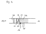
- a Exhaust opening 16 is provided in the connection area between additional heating 12 and mixing chamber 14, which is also the connection area between auxiliary heater 12 and vehicle heater 10.
- a switching flap 18 is articulated in the area of this exhaust air opening 16.
- FIG. 3 shows a perspective view of the second one Embodiment of a changeover door 20.
- the Umschaltklappe 20 can be seen. Make up the first region 26 and the second region 28 in cross section an L-shaped structure, that of the first Area 26 and the second area 28 included angle greater than 90 °. The first area 26 continues an opening 30. This opening can from the cover 32nd be released or closed. by virtue of the forces, the fluid mechanical on the Umschaltklappe Act 20, the changeover 20 can by articulated storage to be pivoted about the axis 34.
- FIG. 5 shows a schematic representation of a part of a Heating system with a second embodiment of a changeover 20 during a second flow state.
- This flow condition is achieved when the back pressure 46, from the direction of the vehicle heater 10 respectively the mixing chamber 14 comes, rises. Is this the Case, then closes the check valve 20 in increasing Dimensions. Will the back pressure 46 so strong that the flow 44 of the auxiliary heater 12 is no longer in the right place Direction can be done, then the check valve 20 completely closed. The build-up dynamic pressure forces the changeover door 20 to tip over. Also closes acting as a non-return flap cover 32, the opening (30, Figure 3) of the first portion 26 of the changeover 20. When the pressure 46 of the vehicle heater 10 decreases, so is through the flow 44 and through this resulting overpressure on the non-return valve 20 forced them to tip over in the other direction again.
- FIGS. 1, 2, 4 and 5 show the switching flaps 18, 20 always in the connecting region between the mixing chamber 14 and the auxiliary heater 12. This is a preferred position of Switching flaps 18, 20. However, there are also other positions possible, for example, directly at the outlet of the auxiliary heater 12 or in the range of mixing chamber 14 or Vehicle heating 10.
- auxiliary heater 12 It can be a smoother Operation of the auxiliary heater 12 take place, in particular requires less control cycles, reducing the burner is charged less in the auxiliary heater 12.
- the heat energy contribution the auxiliary heater 12 can be increased because the maximum heating power is greater. Furthermore, a ensure a clean start and burnout cycle. There no damming and therefore no exhaust port must be provided, less heat energy is lost.
- the additional blower 50 only with a switch-on or Off function to provide. This makes possible a particularly simple control, for example via a relay. But it is also possible, the additional fan 50th steplessly regulate or control. This can be done directly from Heating control unit are made. Also in the case of one On-off control, that means without speed change, For example, the heater controller may issue a triggering signal to generate. It is also possible to over this signal an additional temperature sensor, for example a Bimetal element, regardless of the heater control unit to make.
- Interventions in the operation of the additional blower 50 can under different conditions take place.
- the auxiliary fan For example, it can always be turned on when turns on the heater. In another case that can Switching on the additional blower 50 by switching on the vehicle heating 10 are made dependent. Also can be provided be that just in case of overpowering or Damming the auxiliary fan is switched on.
- FIG. 6 the position of the auxiliary blower 50 is in front of Additional heater 12 shown. This position is to be preferred because in this way the auxiliary fan 50 no heat load is suspended. It is also conceivable that Additional blower 50 in the region of the air inlet 36 to embarrassed. If one chooses an additional blower 50, which is a certain Heat load can withstand, so it is also possible the auxiliary fan 50 behind the auxiliary heater 12, that is between additional heater 12 and mixing chamber 14, to order.
- FIG. 7 shows a diagram in which pressure differences of Press in front of and behind an additional air heater or a vehicle heating applied against the flow are.
- the blower characteristics shown are partial only qualitatively.
- Curve a shows the characteristic curve a blower of a vehicle heater on a high level.
- Curve b shows the characteristic of a comparatively small one Blower of an additional heater at a relatively low speed;
- Curve c shows the characteristic of the same blower at elevated Rotation speed.
- Curve d shows the characteristic curve of a larger blower at a relatively low speed;
- Curve e shows the characteristic curve the same fan at increased speed.
- FIG. 8 shows a schematic representation of a heating system with a non-return valve.
- the illustrated heating system corresponds in many parts to the heating system of the state the technique according to Figures 14 and 15 and the Heating systems, in connection with the figures 1 to 6 were explained.
- additional components are one Non-return valve 56 between the auxiliary heater 12 and the Mixing chamber 14 and the vehicle heater 10 and an additional temperature sensor 58 at the entrance of the Additional heater 12 is provided.
- the additional temperature sensor 58 can directly on the control unit of the auxiliary air heater 12 be attached.
- the sensor should be free in the Air flow, so as to the lowest possible inertia realize.
- the connections and a possibly provided However, plugs on the temperature sensor should be waterproof be.
- the auxiliary heater 12 In the area of the temperature sensor 58 at the entrance of the auxiliary heater 12, however, is the returning air through the auxiliary heater 12 sufficient be heated, so that the temperature rise as reliable Indication of overpressing can be used.
- the auxiliary heater 12 is of a in itself low value, preferably to 100%.
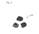
- Figure 9 shows three perspective views of a Check valve in different perspectives respectively States of assembly.
- check valves 56 these have in common that a grid-shaped carrier with one or more on top arranged elastic tabs is provided. The rags can completely cover the grid-shaped carrier.
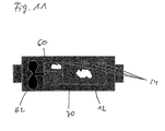
- FIG. 10 shows a schematic representation of an additional air heater 12 with a pressure difference sensor 22. It is furthermore a control unit 60, a blower 62 and a heat exchanger 70 is shown. On the control unit 60 is a Pressure differential sensor 22 attached, which via a pressure line 64 with the area in front of the auxiliary air heater 12, the is the inflow area connected. The pressure difference sensor 22 is thus able to make a difference of one Pressure 66 in front and a pressure 68 behind the auxiliary air heating 12 to measure. This signal can then be sent directly to the controller 60 are entered. Will too much pressure difference determined, so will depending on the embodiment of the remaining heating system on a suppression or a confinement closed. The auxiliary heater 12 is then switched off or in another operating mode transferred.
- a wind direction sensor or a Flow sensor to use. This one is able to detect a flow direction using methods Can be on an impeller, a calorimetric Determination by a heating wire or by ultrasound based. Furthermore, the speed change of a Blowers are used as evidence of overpowering, as the speed increases as soon as the heater is blocked or is suppressed. This increase in Blower speed can be detected by the heater control unit 60 and evaluated.
- FIG. 11 shows a schematic representation of an additional air heater 12 with a plurality of temperature sensors 24, wherein otherwise a similar structure as in Figure 10 are recognized can. These temperature sensors 24 are at different Positions of the auxiliary air heater 12 is arranged.
- the Information of the different temperature sensors 24 can be used in different ways. There is for example, operating conditions in which case in case of Suppression the temperature of the temperature sensor 24 in the area of the control unit 60 and the middle temperature sensor 24 rise while the temperature of the temperature sensor 24 in the area of the output of the additional heating 12 drops. This condition can be used, for example, as an indication be used for a suppression. Likewise the temporal change of the temperature at the temperature sensors be used in a gradient evaluation.
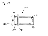
- FIG. 12 shows a schematic representation of a device according to the invention Air heater 210.
- the air heater 210 includes a heat exchanger 270 and one in the region of Heat exchanger 270 arranged temperature sensor 224th This temperature sensor 224 is within the scope of a conventional Overheating protection of the air heater 210 is used.
- a (not shown) burner provided within the heat exchanger 270 .
- this includes Air heater 210, a control unit 260 and a Schubuch devisr or a blower 262 for introducing air to be heated in the air heater 210.
- another temperature sensor 258 is provided, generally in the context of a temperature determination the air entering the air heater 210 is used. On the basis of this temperature determination of the incoming Air can optimize the operation of the air heater 210 become.
- the invention uses that of the temperature sensor 258 captures temperature information to such a situation too avoid.
- the temporal temperature increase in the area of the temperature sensor 258 in the control unit 260 are monitored.
- the measure of the burner in transfers an operating condition with lower heating power; the burner is switched off, for example. optional a cooling lag can be carried out.
- the by the flow reversal induced situation then Take into account when the temperature of the temperature sensor 258 exceeds a certain absolute limit.
- FIG. 13 shows a flow chart for explaining a method according to the invention for detecting backflowing heating air through an air heater.
- a control operation of the control unit is determined in the context of the inventive method, whether the temporal temperature gradient d ⁇ / dt is greater than a maximum temperature gradient (d ⁇ / dt) MAX . If this is the case, the heater can be switched off, for example. In the other case, a further check can be made; it is checked whether the absolute temperature u is greater than a maximum temperature ⁇ MAX . If this is the case, this can also be used as a criterion for switching off the heater, for example. If not, then the normal control operation is transferred, which also means that subsequently again the already described inventive review takes place.
Landscapes
- Engineering & Computer Science (AREA)
- Chemical & Material Sciences (AREA)
- Combustion & Propulsion (AREA)
- Physics & Mathematics (AREA)
- Thermal Sciences (AREA)
- Mechanical Engineering (AREA)
- Air-Conditioning For Vehicles (AREA)
Abstract
Description
Die Erfindung betrifft ein Heizsystem zum Erwärmen von Luft, insbesondere zum Beheizen des Innenraums eines Kraftfahrzeugs, mit mindestens einer ersten Heizung, mindestens einer zweiten Heizung und mindestens einem Strömungsweg zwischen der ersten Heizung und der zweiten Heizung. Die Erfindung betrifft weiterhin ein Verfahren zum Beeinflussen von Luftströmungen in einem Heizsystem zum Erwärmen von Luft, insbesondere zum Beheizen des Innenraums eines Kraftfahrzeugs, mit mindestens einer ersten Heizung, mindestens einer zweiten Heizung und mindestens einem Strömungsweg zwischen der ersten Heizung und der zweiten Heizung. Die Erfindung betrifft ferner ein Luftheizgerät mit einem Brenner, einem Wärmeübertrager, einem Lufteintrittsbereich, einem Luftaustrittsbereich, einem Steuergerät und einem im Lufteintrittsbereich angeordneten Temperatursensor, wobei die Temperatur im Lufteintrittsbereich mittels des im Lufteintrittsbereich angeordneten Temperatursensors überwacht wird. Ebenfalls betrifft die Erfindung ein Verfahren zum Erkennen rückströmender Heizluft durch ein Luftheizgerät.The invention relates to a heating system for heating Air, in particular for heating the interior of a motor vehicle, with at least one first heater, at least a second heater and at least one flow path between the first heater and the second heater. The The invention further relates to a method for influencing of air flows in a heating system for heating Air, in particular for heating the interior of a motor vehicle, with at least one first heater, at least a second heater and at least one flow path between the first heater and the second heater. The Invention further relates to an air heater with a burner, a heat exchanger, an air inlet area, a Air outlet area, a control unit and an im Air inlet region arranged temperature sensor, wherein the temperature in the air inlet area by means of the in the air inlet area monitored temperature sensor monitors becomes. The invention also relates to a method for Detection of backflowing heating air through an air heater.
Insbesondere im Kraftfahrzeugbereich ist es bekannt, gattungsgemäße Heizsysteme und gattungsgemäße Verfahren einzusetzen. Diese zeichnen sich durch das Zusammenwirken einer ersten Heizung - der Fahrzeugheizung beziehungsweise einer Kombination aus Fahrzeugheizung und Klimaanlage - und einer zweiten Heizung - der Luftzusatzheizung - aus. Die Fahrzeugheizung beziehungsweise die Kombination aus Fahrzeugheizung und Klimaanlage wird auch als "Frontbox" bezeichnet. Die Kombination aus Fahrzeugheizung und Klimaanlage ist auch als HVAC ("Heat Ventilation Air Condition") bekannt. Wenn im Folgenden bei der Beschreibung des Standes der Technik und bei der Beschreibung der Erfindung von einer Fahrzeugheizung die Rede ist, so sind stets auch Kombinationen einer Fahrzeugheizung mit einer Klimaanlage gemeint.In particular, in the field of motor vehicles, it is known generic Use heating systems and generic methods. These are characterized by the interaction of a first heating - the vehicle heating or one Combination of vehicle heating and air conditioning - and one second heating - the auxiliary air heating - off. The vehicle heating or the combination of vehicle heating and air conditioning is also referred to as a "front box". The combination of vehicle heating and air conditioning is also known as HVAC ("Heat Ventilation Air Condition"). If below in the description of the state the art and in describing the invention of a Vehicle heating is the case, so are always combinations a vehicle heating with an air conditioner meant.
Figur 14 zeigt schematisch den Aufbau eines Systems des
Standes der Technik. Eine Fahrzeugheizung 110 mit einem
Lufteintritt 138, der nicht näher dargestellt ist, steht
mit einer Mischkammer 114 in Verbindung. Weiterhin ist eine
Zusatzheizung 112 vorgesehen, die einen Lufteintritt 136
aufweist. Auch die Zusatzheizung 112 steht mit der Mischkammer
114 in Verbindung. Die Mischkammer 114 weist mehrere
Luftkanäle 140 für den Austritt von Luft auf. Im Allgemeinen
besteht in der Mischkammer 114 die Möglichkeit, den
dort eintretenden Volumenstrom über Klappen in die unterschiedlichen
Luftkanäle 140 umzuleiten oder Luftkanäle 140
abzuschließen. Auf diese Weise wird dem Benutzer die Möglichkeit
gegeben, umfangreiche Einstellungen zur Klimatisierung
des Innenraums eines Kraftfahrzeugs vorzunehmen.Figure 14 shows schematically the structure of a system of
State of the art. A
Beim normalen Betrieb des Heizsystems gemäß Figur 14 tritt
ein Luftstrom 142 aus der Fahrzeugheizung 110 aus und in
die Mischkammer 114 ein. Ebenso tritt ein Luftstrom 144 aus
der Zusatzheizung 112 aus und in die Mischkammer 114 ein.
Aufgrund dieser an sich voneinander unabhängigen Luftströmungen
142, 144 kann eine Gegenkopplung resultieren, die
beispielsweise zu dem Gegendruck 146 gegen die Strömung 144
der Zusatzheizung 112 führen kann. In Figur 14 hat der Gegendruck
146 einen geringen Betrag, so dass ein ordnungsgemäßes
Arbeiten des Heizsystems möglich ist.During normal operation of the heating system according to Figure 14 occurs
an
In Figur 15 ist ein System dargestellt, welches vom Aufbau
her demjenigen aus Figur 14 entspricht. Im Unterschied zu
dem in Figur 14 schematisch dargestellten Betriebszustand
arbeitet das Heizsystem gemäß Figur 15 nicht ordnungsgemäß.
Dies resultiert aus dem erhöhten Gegendruck 146, der im
dargestellten Fall so groß ist, dass er eine Umkehr der
Luftströmung 144 bewirkt.FIG. 15 shows a system which is of a construction
her corresponds to that of Figure 14. In contrast to
the operating state shown schematically in Figure 14
the heating system according to FIG. 15 does not work properly.
This results from the increased
Das Entstehen der in Figur 14 beziehungsweise in Figur 15 schematisch dargestellten Betriebszustände und die daraus resultierende Problematik wird nachfolgend erläutert.The emergence of the in FIG. 14 and in FIG. 15, respectively schematically illustrated operating conditions and the resulting the resulting problem will be explained below.
Die Fahrzeugheizung besitzt ein Gebläse, das mit hohem Volumenstrom und relativ geringer Drucksteifigkeit Luft in die Mischkammer einbläst. Unter dem Begriff Drucksteifigkeit ist das Potential eines Druckaufbaus zu verstehen. Eine hohe Drucksteifigkeit steht beispielsweise für das Potential, einen hohen Druck aufzubringen. Das Gebläse der Fahrzeugheizung kann stufenlos oder in Stufen geregelt werden, wobei diese Regelung insbesondere unabhängig von den thermodynamischen Zuständen in dem Heizsystem vorgenommen werden kann.The vehicle heater has a blower with a high flow rate and relatively low compressive stiffness air in the mixing chamber blows. Under the term pressure stiffness is the potential of a pressure build-up to understand. A high compressive stiffness stands, for example, for the potential to apply a high pressure. The fan of the Vehicle heating can be steplessly or in stages, this regulation being particularly independent of the thermodynamic conditions in the heating system can be.
Auch die Zusatzheizung besitzt ein Gebläse. Dieses ist im Gegensatz zu dem Gebläse der Fahrzeugheizung relativ drucksteif, wobei jedoch ein geringerer Volumenstrom erzeugt wird. Bei gängigen Zusatzheizungen kann das Gebläse der Zusatzheizung prinzipbedingt nicht unabhängig von der Heizleistung der Zusatzheizung geregelt werden. Wenn mehr Heizleistung benötigt wird, so steigt auch der Volumenstrom an und umgekehrt. Aufgrund der Änderung des Volumenstroms der Zusatzheizung ändert sich aber auch die Drucksteifigkeit. Die Ausblastemperatur an der Zusatzheizung ist unter anderem abhängig von den der Zusatzheizung entgegenwirkenden Widerständen. Dies kann bei hohem Widerstand zu einer erhöhten Ausblastemperatur führen, die durch Herunterregeln oder Abschalten der Zusatzheizung begrenzt wird.The additional heater has a fan. This is in Contrary to the fan of the vehicle heating relatively pressure-resistant, however, producing a lower volume flow becomes. For common auxiliary heaters, the blower of the additional heating principle not independent of the heating power the additional heating are regulated. If more heating power is required, so the volume flow increases and vice versa. Due to the change in the volumetric flow of Additional heating also changes the pressure stiffness. The blow-out temperature at the additional heater is among other things depending on the additional heating counteracting Resistors. This can be increased at high resistance Outlet temperature caused by down regulation or switching off the auxiliary heater is limited.
Für den Betrieb der Zusatzheizung ist es daher ideal, wenn sie bei niedrigen Außentemperaturen mit hohen Heizleistungen, das heißt hohen Volumenströmen und somit hoher Drucksteifigkeit laufen kann. Die Zusatzheizung kann dann dem Gebläse der Fahrzeugheizung entgegenwirken, insbesondere wenn letzteres mit niedrigen Gebläsestufen betrieben wird beziehungsweise wenn nur wenige Klappen in der Mischkammer geschlossen sind.For the operation of the additional heating, it is therefore ideal if at low outside temperatures with high heat outputs, that is, high volume flows and thus high pressure rigidity can run. The additional heating can then the Counteract blower of the vehicle heating, in particular if the latter is operated with low blower levels or if only a few flaps in the mixing chamber are closed.
Problematisch ist allerdings, wenn die Zusatzheizung aufgrund steigender Temperaturen die Heizleistung absenken muss. Aufgrund der vorstehend erläuterten Gesetzmäßigkeiten sinkt dann auch die Drucksteifigkeit und mithin die Möglichkeit, dem Fahrzeuggebläse ausreichend entgegenzuwirken. Ein solcher Zustand hat wiederum zur Folge, dass der Widerstand für die Zusatzheizung immer höher wird und die Zusatzheizung immer weiter die Heizleistung herunterregelt. Problematic, however, if the additional heating due rising temperatures lower the heating power got to. Due to the above explained laws then the pressure stiffness and thus the possibility sufficiently counteract the vehicle fan. In turn, such a condition results in resistance for the additional heating is getting higher and the additional heating continues to down-regulate the heating power.
Dies kann dazu führen, dass der Gegendruck, der durch das Fahrzeugheizungsgebläse erzeugt wird, höher ist als der Druck der Zusatzheizung. Dieser Zustand wird auch als Überdrückung bezeichnet. Die Wärme der Zusatzheizung kann dann nicht mehr abgefördert werden. Im Extremfall wird sie in die umgekehrte Richtung transportiert. Dies kann dazu führen, dass ein im Allgemeinen im Auslassbereich der Zusatzheizung angeordneter Überhitzungsschutz außer Kraft gesetzt werden kann. Weiterhin kann es zu gravierenden Schäden am gesamten System kommen, beispielsweise im Einlassbereich beziehungsweise am Steuergerät der Zusatzheizung.This can cause the back pressure caused by the Vehicle heating fan is generated, higher than that Pressure of additional heating. This condition is also called suppression designated. The heat of the additional heating can then no longer be carried away. In extreme cases, it will be in transported in the opposite direction. This can cause that generally in the outlet area of the auxiliary heater overheated protection overruled can be. Furthermore, it can cause serious damage to the whole system, for example in the inlet area or at the control unit of the additional heater.
Der Erfindung liegt daher die Aufgabe zugrunde, ein Heizsystem und ein Verfahren zur Verfügung zu stellen, welche die genannten Nachteile ausräumen und welche insbesondere eine Überdrückung in dem Heizsystem vermeiden.The invention is therefore based on the object to provide a heating system and a method available, which eliminate the disadvantages mentioned and which in particular avoid overpressing in the heating system.
Diese Aufgabe wird mit den Merkmalen der unabhängigen Ansprüche gelöst. Vorteilhafte Ausführungsformen der Erfindung sind in den abhängigen Ansprüchen angegeben.This object is achieved with the features of the independent claims solved. Advantageous embodiments of the invention are indicated in the dependent claims.
Die Erfindung baut auf dem gattungsgemäßen Heizsystem dadurch, dass mindestens ein Zusatzgebläse vorgesehen ist, mit dem eine Strömung in die Richtung von der zweiten Heizung zu der ersten Heizung erzeugbar ist. Auf diese Weise ist es möglich, den Volumenstrom beziehungsweise den Druck von der zweiten Heizung in Richtung der Fahrzeugheizung so weit zu erhöhen, dass die zweite Heizung unter beliebigen Bedingungen nicht überdrückt wird. Ferner ist keine Verdämmung der Strömungsverbindung zwischen der zweiten Heizung und der Fahrzeugheizung erforderlich, wobei gleichwohl ein stabiler und schonender Heizgerätebetrieb gewährleistet wird. Auf diese Weise kann auch bei niedrigen Drehzahlen der zweiten Heizung eine Überdrückung verhindert werden. Im zweiten Heizgerät herrschen durchschnittlich geringere Temperaturen, so dass die Bauteile weniger belastet werden. Es kann ein gleichmäßiger Betrieb der zweiten Heizung stattfinden, der insbesondere weniger Regelzyklen erfordert, wodurch ein Brenner in der zweiten Heizung weniger belastet wird. Weiterhin kann der Wärmeenergiebeitrag der zweiten Heizung erhöht werden, da die Maximalheizleistung größer wird. Es kann ein sauberer Start- und Ausbrennzyklus gewährleistet werden. Da es nicht erforderlich ist, die Strömungsverbindung zwischen der ersten Heizung und der zweiten Heizung zu unterbrechen, wird die Wärmeenergie aus der zweiten Heizung stets optimal ausgenutzt.The invention is based on the generic heating system characterized, that at least one additional blower is provided, with the one flow in the direction of the second heater can be generated to the first heater. In this way it is possible, the flow or the pressure from the second heater in the direction of the vehicle heater so Far increase that the second heater under any Conditions are not overridden. Furthermore, there is no damming the flow connection between the second heater and the vehicle heating required, although a stable and gentle heater operation guaranteed becomes. This way, even at low speeds the second heater will prevent overpressing. in the second heater prevail on average lower temperatures, so that the components are less stressed. It can a uniform operation of the second heating take place, which in particular requires fewer control cycles, whereby a burner in the second heater less loaded becomes. Furthermore, the heat energy contribution of the second Heating can be increased because the maximum heating power is greater becomes. It can ensure a clean start and burnout cycle become. Since it is not necessary, the flow connection between the first heater and the second To interrupt heating, the heat energy from the second heating always optimally utilized.
Die Erfindung entfaltet ihre Vorteile besonders dadurch, dass die erste Heizung eine Fahrzeugheizung ist und dass die zweiten Heizung eine Zusatzheizung ist. Die Erfindung ist in vorteilhafter Weise für das Zusammenspiel von Heizungen in beliebigen Umgebungen einsetzbar. Besondere Vorzüge ergeben sich aber beim Einsatz in einem Kraftfahrzeug. Dort werden Zusatzheizungen häufig mit Fahrzeugheizungen beziehungsweise mit Fahrzeugheizungssystemen kombiniert, die sich bereits in der Anwendung befinden. Die Erfindung eröffnet durch die Bereitstellung stabiler Strömungsbedingungen der einzubindenden Zusatzheizung in ein Fahrzeugsystem eines Kraftfahrzeugs die Möglichkeit einer problemlosen Integration.The invention develops its advantages in particular by that the first heater is a vehicle heater and that the second heater is an auxiliary heater. The invention is advantageous for the interaction of heaters can be used in any environment. Special advantages but arise when used in a motor vehicle. There are additional heaters often with vehicle heaters or combined with vehicle heating systems, that are already in use. The invention opened by the provision of stable flow conditions the additional heater to be incorporated in a vehicle system a motor vehicle the possibility of a problem-free Integration.
Vorzugsweise ist mindestens eine Mischkammer vorgesehen, in die aus der mindestens einen ersten Heizung und aus der mindestens einen zweiten Heizung ausgeströmte Luft eintreten kann. Eine solche Mischkammer ist nützlich, um Luft mit einer einheitlichen Temperatur in den Innenraum des Kraftfahrzeugs einzuleiten. Die Verbindung der Fahrzeugheizung mit der Zusatzheizung besteht dann im Allgemeinen über diese Mischkammer, wobei es auch dann zu der Problematik der Überdrückung kommen kann. Insbesondere weist eine Mischkammer häufig Klappen auf, mit denen Kanäle ganz oder teilweise verschlossen werden können, so dass der Gegendruck gegen die Strömung aus der Zusatzheizung sehr hoch werden kann.Preferably, at least one mixing chamber is provided, in from the at least one first heater and out of the Enter at least one second heater emitted air can. Such a mixing chamber is useful to air with a uniform temperature in the interior of the motor vehicle initiate. The connection of the vehicle heating with the additional heating is then generally about this It is also the problem of the Overpressure can come. In particular, a mixing chamber often flaps on, with which channels in whole or in part can be closed, so that the back pressure against the flow from the additional heating can be very high.
Es ist besonders vorteilhaft, dass das Zusatzgebläse vor der zweiten Heizung angeordnet ist. Diese Position ist zu bevorzugen, da auf diese Weise das Zusatzgebläse keiner Wärmebelastung ausgesetzt wird. Ebenfalls ist es denkbar, das Zusatzgebläse in den Bereich eines Lufteintritts für die Zusatzheizung zu verlegen. Es liegt jedoch auch im Umfang der vorliegenden Erfindung, ein Zusatzgebläse hinter der Zusatzheizung anzuordnen. Dies ist insbesondere dann möglich, wenn man ein Zusatzgebläse wählt, das einer höheren Wärmebelastung standhält.It is particularly advantageous that the auxiliary fan before the second heater is arranged. This position is too prefer, because in this way the auxiliary fan none Heat load is exposed. It is also conceivable the auxiliary fan in the area of an air intake for to lay the additional heating. However, it is also in scope the present invention, an additional blower behind to arrange the auxiliary heater. This is especially true possible if one chooses an auxiliary fan, the one higher Heat load withstands.
In einer weiteren besonders bevorzugten Ausführungsform ist das erfindungsgemäße Heizsystem dadurch weitergebildet, dass das Zusatzgebläse in Abhängigkeit eines Ausgangssignals eines Steuergerätes betätigbar ist. Ein solches Steuergerät kann zahlreiche Eingangsdaten bei der Entscheidung, ob das Zusatzgebläse zu betätigen ist, einbeziehen. Dabei kommen Eingangssignale in Frage, die direkt mit dem Heizsystem in Verbindung stehen. Es können aber auch andere Signale verwertet werden, beispielsweise CAN-Bus-Signale.In a further particularly preferred embodiment the heating system according to the invention thereby developed, that the auxiliary fan in response to an output signal a control unit is actuated. Such a controller can handle numerous input data when deciding whether the auxiliary blower is to be operated, involve. there Input signals come into direct contact with the heating system keep in touch. But there are others too Signals are utilized, for example, CAN bus signals.
Es ist von besonderem Vorteil, dass zum Erfassen von Druckzuständen in dem Heizsystem mindestens ein Drucksensor zum Erzeugen eines Eingangssignals für ein Steuergerät vorgesehen ist. Ein solcher Drucksensor kann beispielsweise als Differenzdrucksensor ausgelegt sein, wobei die Differenz zwischen dem Druck vor dem Zusatzheizgerät und dem Druck im beziehungsweise nach dem Zusatzheizgerät gemessen wird. Bei zu hoher Differenz liegt mit hoher Wahrscheinlichkeit eine Überdrückung vor, so dass von dem Steuergerät Maßnahmen eingeleitet werden können, beispielsweise das Zuschalten des Zusatzgebläses. Allerdings ist zu bemerken, dass die Druckdifferenz nicht in jedem Fall ein spezifisches Merkmal für eine Verdämmung ist. Es ist auch möglich, dass bei niedrigen Drücken eine Verdämmung auftritt. Ebenfalls kann beispielsweise bei hohen Drehzahlen ein hoher Druck ohne Verdämmung vorliegen.It is of particular advantage that for detecting pressure conditions in the heating system at least one pressure sensor for Generating an input signal for a controller provided is. Such a pressure sensor can, for example, as Differential pressure sensor designed to be the difference between the pressure in front of the auxiliary heater and the pressure in the or after the additional heater is measured. at too high a difference is most likely one Overpressure before, so that measures from the control unit can be initiated, for example, the connection the auxiliary fan. However, it should be noted that the Pressure difference is not always a specific feature for a damming is. It is also possible that at low pressures a damming occurs. Likewise For example, at high speeds a high pressure without Damming present.
Im gleichen Sinne ist es zu bevorzugen, dass zum Erfassen von Temperaturzuständen in dem Heizsystem mindestens ein Temperatursensor zum Erzeugen eines Eingangssignals für ein Steuergerät vorgesehen ist. Die Auswertung der Temperatursignale kann beispielsweise durch eine Gradientenauswertung erfolgen. Ist ein Temperatursensor zum Beispiel in den Nähe des Ausgangs der Zusatzheizung installiert, so kann es bei einer Überdrückung zu einem schlagartigen Temperaturabfall im Bereich dieses Temperatursensors kommen. Da ein solcher Temperaturabfall bei einer gleichbleibenden oder steigenden Heizleistung ohne das Vorliegen einer Überdrückung nicht vorliegen könnte, kann aus dem Temperaturabfall auf eine Überdrückung geschlossen werden. Ebenfalls ist es möglich, mehrere Temperatursensoren im Bereich der Zusatzheizung zu installieren und aus dem räumlichen Temperaturverlauf auf eine eventuell vorliegende Überdrückung zu schließen.In the same sense, it is preferable that to capture of temperature conditions in the heating system at least one Temperature sensor for generating an input signal for a Control unit is provided. The evaluation of the temperature signals can for example by a gradient evaluation respectively. For example, if a temperature sensor is nearby the output of the auxiliary heater installed, it may be at a suppression to a sudden drop in temperature come in the range of this temperature sensor. Because such a Temperature drop at a steady or rising Heating power without the presence of a suppression not could be from the temperature drop to one Suppression be closed. It is also possible several temperature sensors in the additional heating to install and out of the spatial temperature history to close any suppression.
Besonders bevorzugt ist es, dass das Zusatzgebläse regelbar ist. Eine solche Regelung kann stufenlos oder auch in Stufen erfolgen, wobei diese Regelaufgaben vorzugsweise vom Steuergerät der Zusatzheizung übernommen werden. Ebenfalls ist es möglich, eine in Stufen erfolgende beziehungsweise eine stufenlose Steuerung vorzusehen. Bei einer anderen Betriebsart kann das System so ausgelegt sein, dass das Zusatzgebläse nur ein- beziehungsweise ausgeschaltet wird. Hierzu kann beispielsweise ein Relais verwendet werden. It is particularly preferred that the auxiliary fan can be regulated is. Such a scheme can be stepless or in stages take place, these control tasks preferably from Control unit of the additional heating are taken over. Also Is it possible to do one in stages, respectively to provide a stepless control. In another mode The system can be designed so that the auxiliary fan only on or off. For this purpose, for example, a relay can be used.
Es kann ebenfalls vorteilhaft sein, dass das Zusatzgebläse direkt in Abhängigkeit eines Ausgangssignals eines Temperatursensors betätigbar ist. Ein solcher Temperatursensor kann beispielsweise ein Bimetallelement sein, so dass eine Ansteuerung des Zusatzgebläses unabhängig von einem Steuergerät erfolgen kann.It may also be advantageous that the auxiliary fan directly in response to an output signal of a temperature sensor is operable. Such a temperature sensor For example, may be a bimetallic element, so that a Control of the additional blower independent of a control unit can be done.
Die Erfindung baut auf dem gattungsgemäßen Verfahren dadurch auf, dass durch mindestens ein Zusatzgebläse eine Strömung in die Richtung von der zweiten Heizung zu der ersten Heizung erzeugt wird. Auf diese Weise werden die im Zusammenhang mit dem Heizsystem erläuterten Eigenschaften und Vorzüge der Erfindung auch im Rahmen eines Verfahrens realisiert. Dies gilt ebenso für die nachfolgend genannten Ausführungsformen des Verfahrens.The invention is based on the generic method thereby on that by at least one additional blower a Flow in the direction from the second heater to the first heating is generated. In this way, the im Related to the heating system explained properties and advantages of the invention also in the context of a method realized. This also applies to the following Embodiments of the method.
Die Erfindung entfaltet ihre Vorteile besonders dadurch, dass die erste Heizung eine Fahrzeugheizung ist und dass die zweiten Heizung eine Zusatzheizung ist.The invention develops its advantages in particular by that the first heater is a vehicle heater and that the second heater is an auxiliary heater.
Vorzugsweise ist mindestens eine Mischkammer vorgesehen, in die aus der mindestens einen ersten Heizung und aus der mindestens einen zweiten Heizung ausgeströmte Luft eintreten kann.Preferably, at least one mixing chamber is provided, in from the at least one first heater and out of the Enter at least one second heater emitted air can.
Von besonderem Vorteil ist es, dass das Zusatzgebläse in Abhängigkeit eines Ausgangssignals eines Steuergerätes betätigt wird.Of particular advantage is that the auxiliary fan in Dependence of an output signal of a control unit operated becomes.
Im vorgenannten Zusammenhang ist es von besonderem Vorteil, dass Druckzustände in dem Heizsystem von mindestens einem Drucksensor erfasst werden und dass ein druckabhängiges Eingangssignal für ein Steuergerät erzeugt wird. In the aforementioned context, it is of particular advantage that pressure conditions in the heating system of at least one Pressure sensor to be detected and that a pressure-dependent Input signal is generated for a control unit.
Im gleichen Sinne ist es zu bevorzugen, dass Temperaturzustände in dem Heizsystem von mindestens einem Temperatursensor erfasst werden und dass ein temperaturabhängiges Eingangssignal für ein Steuergerät erzeugt wird.In the same sense, it is preferable that temperature conditions in the heating system of at least one temperature sensor be detected and that a temperature-dependent Input signal is generated for a control unit.
Weiterhin kann es nützlich sein, dass das Zusatzgebläse geregelt wird.Furthermore, it may be useful for the auxiliary fan to be regulated becomes.
In einer anderen nützlichen Ausführungsform des erfindungsgemäßen Verfahrens ist vorgesehen, dass das Zusatzgebläse direkt in Abhängigkeit eines Ausgangssignals eines Temperatursensors betätigt wird.In another useful embodiment of the invention Method is provided that the auxiliary fan directly in response to an output signal of a temperature sensor is pressed.
Es kann nützlich sein, dass das Zusatzgebläse eingeschaltet beziehungsweise ausgeschaltet wird, wenn die zweite Heizung eingeschaltet beziehungsweise ausgeschaltet wird. Das Zusatzgebläse wird also nur unterstützend für das Gebläse der zweiten Heizung eingesetzt und insbesondere nur während des Heizbetriebs der zweiten Heizung.It may be useful to turn on the auxiliary fan or turned off when the second heater is switched on or off. The auxiliary fan So it is only supportive for the fan of the second heater used and especially only during the Heating operation of the second heater.
Es kann aber auch nützlich sein, dass das Zusatzgebläse eingeschaltet beziehungsweise ausgeschaltet wird, wenn die erste Heizung eingeschaltet wird. Da die Gefahr einer Überdrückung des Heizsystems während der Einschaltphase des ersten Heizsystems besteht, kann eine solche Betriebsart des Zusatzgebläses sinnvoll sein.It may also be useful for the auxiliary fan is switched on or off when the first heating is switched on. Because the danger of being overpowered of the heating system during the switch-on of the first heating system can be such an operating mode make the additional fan sense.
In einer weiteren Variante wird das Zusatzgebläse eingeschaltet, wenn eine Überdrückung des Heizsystems erkannt wird. Auf diese Weise wird die Betriebszeit des Zusatzgebläses minimiert, da es nur dann eingeschaltet ist, wenn der Zustand vorliegt, für den das Heizsystem mit Zusatzgebläse konzipiert ist. In a further variant, the auxiliary fan is turned on, if a suppression of the heating system detected becomes. In this way, the operating time of the additional blower minimized, since it is only switched on, if the condition is present for which the heating system with auxiliary blower is designed.
Die Erfindung baut auf dem gattungsgemäßen Luftheizgerät dadurch auf, dass beim Überschreiten eines Grenzwertes durch eine temperaturabhängige Größe der Brenner in einen Zustand mit niedrigerer Heizleistung überführt wird. Auf diese Weise wird der im Normalbetrieb zur Bestimmung der Lufteintrittstemperatur genutzte Temperatursensor im Lufteintrittsbereich des Luftheizgerätes dazu verwendet, eine Rückströmung von aufgeheizter Luft zu ermitteln. Dies erfolgt über die Bestimmung einer temperaturabhängigen Größe. Falls diese temperaturabhängige Größe einen bestimmten Grenzwert überschreitet, können Gegenmaßnahmen ergriffen werden, bei denen insbesondere der Brenner in einen Zustand mit niedrigerer Heizleistung überführt wird. Folglich wird einer unerwünschten Überhitzung elektronischer Komponenten, beispielsweise im Bereich des Steuergerätes, entgegengewirkt.The invention is based on the generic air heater in that when a limit value is exceeded by a temperature-dependent size of the burner in one Condition is transferred with lower heating power. On This is the normal mode for determining the Air inlet temperature used temperature sensor in the air inlet area of the air heater used to a Recirculation of heated air to determine. this happens on the determination of a temperature-dependent variable. If this temperature-dependent size a certain Exceeds limit, countermeasures can be taken in particular, the burner in a state is transferred with lower heating power. Consequently, will unwanted overheating of electronic components, for example, in the area of the control unit, counteracted.
Beispielsweise kann das erfindungsgemäße Luftheizgerät in der Weise verwendet werden, dass beim Überschreiten eines Grenzwertes durch eine temperaturabhängige Größe der Brenner abgeschaltet wird. Folglich wird eine weitere Erwärmung von Heizluft auf ein Minimum zurückgeführt, wodurch eine besonders effektive Gegenmaßnahme zur Verfügung gestellt wird.For example, the air heater according to the invention in the way that when crossing a Limit value by a temperature-dependent size of the burner is switched off. Consequently, a further warming of heating air is reduced to a minimum, creating a particularly effective countermeasure provided becomes.
Weiterhin kann im Rahmen der vorliegenden Erfindung vorgesehen sein, dass als temperaturabhängige Größe der zeitliche Temperaturgradient verwendet wird, so dass beim Überschreiten eines maximalen positiven Temperaturgradienten der Brenner abgeschaltet wird. Die Geschwindigkeit des Temperaturanstiegs kann daher als Kriterium verwendet werden, da ein quasi schlagartiger Temperaturanstieg auf eine einsetzende Strömungsumkehr schließen lässt. Durch die Überwachung des Temperaturgradienten lässt sich daher frühzeitig eine Gegenmaßnahme gegen die Strömungsumkehr beziehungsweise gegen eine Überhitzung der im Eintrittsbereich vorhandenen Komponenten ergreifen.Furthermore, it can be provided within the scope of the present invention be that as a temperature-dependent size of the temporal Temperature gradient is used, so when exceeding a maximum positive temperature gradient the burner is switched off. The speed of the temperature rise can therefore be used as a criterion because a quasi-sudden temperature rise to an incipient Closing flow reversal. By monitoring the temperature gradient can therefore be early a countermeasure against the flow reversal, respectively against overheating of existing in the inlet area Take components.
Ebenfalls ist es alternativ oder zusätzlich zur Gradientenauswertung möglich, dass als temperaturabhängige Größe die Temperatur selbst verwendet wird, so dass beim Überschreiten einer maximalen Temperatur der Brenner abgeschaltet wird. Steigt beispielsweise die Temperatur im Bereich des Temperatursensors im Lufteintrittsbereich nur langsam an, so ist hierdurch eine zusätzliche Sicherheit gegeben.It is also alternative or in addition to the gradient evaluation possible that as temperature-dependent size the Temperature itself is used, so when crossing switched off a maximum temperature of the burner becomes. For example, if the temperature increases in the range of Temperature sensor in the air inlet area only slowly, this provides additional security.
Ebenfalls ist es möglich, dass mit beziehungsweise nach dem Überführen des Brenners in einen Zustand mit niedrigerer Heizleistung ein Kühlnachlauf durchgeführt wird. Ein solcher Kühlnachlauf bewirkt, dass eventuell bereits in einem kritischen Temperaturzustand befindliche Komponenten rasch wieder abgekühlt werden können, so dass danach wieder in einen normalen Brennerbetrieb übergegangen werden kann.It is also possible that with or after the Transfer the burner to a lower state Heating power a cooling lag is performed. Such a Cooling caster causes that possibly already in one critical temperature state components quickly can be cooled down again, so that afterwards in a normal burner operation can be passed.
Die Erfindung besteht weiterhin in einem Verfahren zum Erkennen rückströmender Heizluft durch ein Luftheizgerät, bei dem die Temperatur in einem Lufteintrittsbereich mittels eines im Lufteintrittsbereich angeordneten Temperatursensors überwacht wird und beim Überschreiten eines Grenzwertes durch eine temperaturabhängige Größe der Brenner des Luftheizgerätes in einen Zustand mit niedrigerer Heizleistung überführt wird. Auf diese Weise werden die im Zusammenhang mit dem erfindungsgemäßen Luftheizgerät geschilderten Vorteile auch im Rahmen eines Verfahrens umgesetzt. Dies gilt auch für die nachfolgend angegebenen vorteilhaften Ausführungsformen des erfindungsgemäßen Verfahrens zum Erkennen rückströmender Heizluft. The invention further consists in a method for detecting returning hot air through an air heater, at the temperature in an air inlet area means a temperature sensor arranged in the air inlet region is monitored and when a limit value is exceeded by a temperature dependent size of the burner of the Air heater in a state with lower heat output is transferred. That way they are related described with the air heater according to the invention Advantages also implemented in the context of a procedure. This also applies to the following advantageous Embodiments of the method according to the invention for Recognizing backflowing heating air.
Das erfindungsgemäße Verfahren ist besonders dann vorteilhaft, wenn beim Überschreiten eines Grenzwertes durch eine temperaturabhängige Größe der Brenner abgeschaltet wird.The method according to the invention is particularly advantageous when exceeding a limit by a temperature-dependent size of the burner is switched off.
Ebenfalls ist es besonders nützlich, wenn als temperaturabhängige Größe der zeitliche Temperaturgradient verwendet wird, so dass beim Überschreiten eines maximalen positiven Temperaturgradienten der Brenner abgeschaltet wird beziehungsweise in einen Zustand mit niedrigerer Heizleistung überführt wird.It is also particularly useful when as a temperature-dependent Size of the temporal temperature gradient used will, so when exceeding a maximum positive Temperature gradient of the burner is switched off or in a state with lower heating power is transferred.
Weiterhin kann das erfindungsgemäße Verfahren besonders dadurch vorteilhaft ausgelegt sein, dass zusätzlich oder alternativ zur Gradientenauswertung als temperaturabhängige Größe die Temperatur selbst verwendet wird, so dass beim Überschreiten einer maximalen Temperatur der Brenner abgeschaltet wird.Furthermore, the method according to the invention can be characterized in particular be designed advantageously that additionally or alternatively for gradient evaluation as temperature-dependent Size the temperature itself is used, so that when Exceeding a maximum temperature of the burner switched off becomes.
Ebenfalls kann es im Rahmen des erfindungsgemäßen Verfahrens nützlich sein, dass mit beziehungsweise nach dem Überführen des Brenners in einen Zustand mit niedriger Heizleistung ein Kühlnachlauf durchgeführt wird.It may also be in the context of the method according to the invention be useful with or after the transfer of the burner in a state with low heat output a cooling lag is performed.
Der Erfindung liegt die Erkenntnis zugrunde, dass eine Überdrückung und die damit verbundenen Probleme im Bereich einer Luftzusatzheizung durch das Bereitstellen eines Zusatzgebläses überwunden werden können. Auf diese Weise kann sichergestellt werden, dass der Volumenstrom und die Drucksteifigkeit in die Richtung von der zweiten Heizung zu der ersten Heizung immer ausreichend sind, um den Gegendruck zu überwinden, der von der Fahrzeugheizung erzeugt wird. Das Erkennen einer Strömungsumkehr innerhalb des Luftheizgerätes kann zum Beispiel mit Hilfe einer Auswertung eines zeitlichen Temperaturgradienten erfolgen. The invention is based on the finding that an overpressing and the related problems in the field an additional air heating by providing an additional blower can be overcome. This way you can ensure that the volume flow and the pressure stiffness in the direction of the second heater to the first heater are always sufficient to counter pressure overcome, which is generated by the vehicle heating. The Recognizing a flow reversal within the air heater For example, with the help of an evaluation of a temporal temperature gradient.
Die Erfindung wird nun mit Bezug auf die begleitenden Zeichnungen anhand bevorzugter Ausführungsformen beispielhaft erläutert.The invention will now be described with reference to the accompanying drawings Drawings based on preferred embodiments by way of example explained.
Dabei zeigt:
Figur 1- eine schematische Darstellung eines Heizsystems mit einer ersten Ausführungsform einer Umschaltklappe;
- Figur 2
- eine schematische Darstellung eines Teils eines Heizsystems mit einer zweiten Ausführungsform einer Umschaltklappe;
- Figur 3
- eine perspektivische Darstellung der zweiten Ausführungsform einer Umschaltklappe;
- Figur 4
- eine schematische Darstellung eines Teils eines Heizsystems mit einer zweiten Ausführungsform einer Umschaltklappe während eines ersten Strömungszustandes;
- Figur 5
- eine schematische Darstellung eines Teils eines Heizsystems mit einer zweiten Ausführungsform einer Umschaltklappe während eines zweiten Strömungszustandes;
- Figur 6
- eine schematische Darstellung eines Heizsystems mit einem Zusatzgebläse;
- Figur 7
- ein Diagramm, bei dem Druckdifferenzen von Drücken vor und hinter einer Luftzusatzheizung beziehungsweise einer Fahrzeugheizung gegen den Volumenstrom aufgetragen sind;
- Figur 8
- eine schematische Darstellung eines Heizsystems mit einer Rückschlagklappe;
Figur 9- drei perspektivische Darstellungen einer Rückschlagklappe in verschiedenen Perspektiven beziehungsweise Montagezuständen;
Figur 10- eine schematische Darstellung einer Luftzusatzheizung mit einem Druckdifferenzsensor;
- Figur 11
- eine schematische Darstellung einer Luftzusatzheizung mit Temperatursensoren;
Figur 12- eine schematische Darstellung eines erfindungsgemäßen Luftheizgerätes;
- Figur 13
- ein Flussdiagramm zur Erläuterung eines erfindungsgemäßen Verfahrens zum Erkennen rückströmender Heizluft durch ein Luftheizgerät;
Figur 14- eine schematische Darstellung eines Heizsystems des Standes der Technik mit einem unkritischen Strömungszustand; und
- Figur 15
- eine schematische Darstellung eines Heizsystems des Standes der Technik mit einem kritischen Strömungszustand.
- FIG. 1
- a schematic representation of a heating system with a first embodiment of a switching valve;
- FIG. 2
- a schematic representation of a portion of a heating system with a second embodiment of a switching valve;
- FIG. 3
- a perspective view of the second embodiment of a changeover valve;
- FIG. 4
- a schematic representation of a portion of a heating system with a second embodiment of a changeover during a first flow state;
- FIG. 5
- a schematic representation of a portion of a heating system with a second embodiment of a changeover during a second flow state;
- FIG. 6
- a schematic representation of a heating system with an additional fan;
- FIG. 7
- a diagram in which pressure differences of pressures in front of and behind an additional air heater or a vehicle heater are plotted against the flow;
- FIG. 8
- a schematic representation of a heating system with a non-return valve;
- FIG. 9
- three perspective views of a check valve in different perspectives or mounting states;
- FIG. 10
- a schematic representation of an additional air heater with a pressure difference sensor;
- FIG. 11
- a schematic representation of an additional air heating with temperature sensors;
- FIG. 12
- a schematic representation of an air heater according to the invention;
- FIG. 13
- a flowchart for explaining a method according to the invention for detecting backflowing heating air by an air heater;
- FIG. 14
- a schematic representation of a heating system of the prior art with a non-critical flow state; and
- FIG. 15
- a schematic representation of a heating system of the prior art with a critical flow state.
Bei der nachfolgenden Beschreibung der Zeichnungsfiguren bezeichnen gleiche Bezugszeichen gleiche oder vergleichbare Elemente.In the following description of the drawing figures like reference characters designate the same or similar Elements.
Figur 1 zeigt eine schematische Darstellung eines Heizsystems
mit einer ersten Ausführungsform einer Umschaltklappe
18. Eine Fahrzeugheizung 10 mit einem Lufteintritt 38, der
nicht näher dargestellt ist, steht mit einer Mischkammer 14
in Verbindung. Weiterhin ist eine Zusatzheizung 12 vorgesehen,
die einen Lufteintritt 36 aufweist. Auch die Zusatzheizung
12 kann mit der Mischkammer 14 verbunden sein. Die
Mischkammer 14 weist mehrere Luftkanäle 40 für den Austritt
von Luft auf. Im Allgemeinen besteht in der Mischkammer 14
die Möglichkeit, den dort eintretenden Volumenstrom über
Klappen in die unterschiedlichen Luftkanäle 40 umzuleiten
oder Luftkanäle 40 abzuschließen. Auf diese Weise wird dem
Benutzer die Möglichkeit gegeben, umfangreiche Einstellungen
zur Klimatisierung des Innenraums des Kraftfahrzeugs
vorzunehmen.FIG. 1 shows a schematic representation of a heating system
with a first embodiment of a switching
Weiterhin ist in dem Verbindungsbereich zwischen Zusatzheizung
12 und Mischkammer 14, der auch der Verbindungsbereich
zwischen Zusatzheizung 12 und Fahrzeugheizung 10 ist, eine
Abluftöffnung 16 vorgesehen. Im Bereich dieser Abluftöffnung
16 ist eine Umschaltklappe 18 gelenkig angeordnet.Furthermore, in the connection area between
Die Umschaltklappe 18 ist in zwei Zuständen gezeigt und daher
mit unterbrochenen Linien dargestellt. Im ersten
Schaltzustand verschließt die Umschaltklappe 18 die Abluftöffnung
16, und es besteht eine Verbindung zwischen der Zusatzheizung
12 und der Mischkammer 14 beziehungsweise der
Fahrzeugheizung 10. In einem zweiten Schaltzustand verschließt
die Umschaltklappe 18 diese Verbindung zwischen
Zusatzheizung 12 und Mischkammer 14; die Abluftöffnung 16
wird hingegeben freigegeben. Das Heizsystem mit dem ersten
Zustand der Umschaltklappe 16 entspricht also strömungstechnisch
vom Prinzip her dem Heizsystem des Standes der
Technik, das anhand der Figuren 14 und 15 erläutert wurde.
Dieser erste Zustand der Umschaltklappe kann also dann eingenommen
werden, wenn ein zulässiger Strömungszustand vorliegt,
wie er anhand von Figur 14 erläutert wurde, insbesondere
also dann, wenn keine Überdrückung durch einen Gegendruck
46 vorliegt, der letztlich aus der ausströmenden
Luft 42 aus der Fahrzeugheizung 10 resultiert. In dem Fall
hat die Strömung 44 aus der Zusatzheizung 12 eine ausreichende
Drucksteifigkeit, um in die Mischkammer 14 zu gelangen.
Erhöht sich der Gegendruck 46 jedoch, so dass es
letztlich zu einer Strömungsumkehr der Strömung 44 aus der
Zusatzheizung 12 kommen könnte, so verschließt die Umschaltklappe
18 die Verbindung zwischen der Zusatzheizung
12 und der Mischkammer 14 beziehungsweise der Fahrzeugheizung
10 und gibt die Abluftöffnung 16 frei. Die Strömung 44
aus der Zusatzheizung 12 kann dann durch die Abluftöffnung
16 austreten. Somit kann die mitunter stark aufgeheizte Zusatzheizung
12 abkühlen.The switching
Das Umschalten der Umschaltklappe 18 kann beispielsweise
durch einen (nicht dargestellten) elektrischen Stellmotor
erfolgen, der von einem Ausgangssignal eines (nicht dargestellten)
Steuergerätes aktiviert wird. Dieses Steuergerät
kann eine Vielzahl von Eingangssignalen verarbeiten, beispielsweise
Druck beziehungsweise Temperatur an verschiedenen
Positionen des Heizsystems. Wenn nach einer gewissen
Zeit des Abströmens der Strömung 44 aus der Zusatzheizung
12 durch die Abluftöffnung 16 davon auszugehen ist, dass
die Zusatzheizung 12 ausreichend abgekühlt ist, kann die
Umschaltklappe 18 wieder in den ersten Zustand überführt
werden, da dann mit einer gewissen Wahrscheinlichkeit die
Drucksteifigkeit der Strömung 44 wieder ausreicht, so dass
sie den Gegendruck 46 überwinden kann.The switching of the switching
Figur 2 zeigt eine schematische Darstellung eines Teils eines
Heizsystems mit einer zweiten Ausführungsform einer Umschaltklappe
20. Die strömungsmechanisch betätigte Umschaltklappe
20 ist im vorliegenden Beispiel in der Verbindungsleitung
zwischen der Fahrzeugheizung 10 beziehungsweise
der Mischkammer 14 und der Zusatzheizung 12 angeordnet. Figure 2 shows a schematic representation of a part of a
Heating system with a second embodiment of a
Sie befindet sich daher im Bereich der Strömung 44, die von
der Zusatzheizung erzeugt wird, und des Gegendruckes 46,
der von dem Gebläse der Fahrzeugheizung 10 erzeugt wird.
Die Umschaltklappe 20 hat einen ersten Bereich 26, der in
den Strömungsbereich hineinragt. Ein zweiter Bereich 28
dient dem Verschließen beziehungsweise dem Freigeben einer
Abluftöffnung 16. Die Umschaltklappe 20 ist weiterhin mit
einer Abdeckung 32 an ihrem ersten Bereich 26 ausgestattet,
die vorliegend als Elastomerlappen realisiert ist. Die Umschaltklappe
20 ist mittels einer Achse 34 gelenkig gelagert.It is therefore in the area of the
Figur 3 zeigt eine perspektivische Darstellung der zweiten
Ausführungsform einer Umschaltklappe 20. Eine mögliche Gestaltung
der Umschaltklappe 20 ist zu erkennen. Dabei bilden
der erste Bereich 26 und der zweite Bereich 28 im Querschnitt
eine L-förmige Struktur, wobei der von dem ersten
Bereich 26 und dem zweiten Bereich 28 eingeschlossene Winkel
größer ist als 90°. Der erste Bereich 26 hat weiterhin
eine Öffnung 30. Diese Öffnung kann von der Abdeckung 32
freigegeben beziehungsweise verschlossen werden. Aufgrund
der Kräfte, die strömungsmechanisch auf die Umschaltklappe
20 wirken, kann die Umschaltklappe 20 durch gelenkige Lagerung
um die Achse 34 geschwenkt werden.FIG. 3 shows a perspective view of the second one
Embodiment of a
Figur 4 zeigt eine schematische Darstellung eines Teils eines
Heizsystems mit einer zweiten Ausführungsform einer Umschaltklappe
20 während eines ersten Strömungszustandes. In
dem hier dargestellten Strömungszustand ist der Gegendruck
46 der Fahrzeugheizung 10 gering. Somit kann die Zusatzheizung
12 eine Strömung 44 in die richtige Richtung ausbilden.
Die Umschaltklappe 20 wird hierdurch in Richtung der
Fahrzeugheizung 10 beziehungsweise der Mischkammer 14 gedrückt,
und die als Rückschlagklappe wirkende Abdeckung 32
öffnet sich. Der zweite Bereich 28 der Umschaltklappe 20
verschließt die Abluftöffnung 16. Damit es nicht zu einem
unbeabsichtigten Öffnen der Abluftöffnung 16 kommt, obwohl
an sich ein korrekter Betrieb erfolgen kann, sind die an
der Strömungsmechanik beteiligten Flächen, das heißt der
erste Bereich 26, der zweite Bereich 28 und die Abdeckung
32 entsprechend aufeinander abgestimmt.Figure 4 shows a schematic representation of a part of a
Heating system with a second embodiment of a
Figur 5 zeigt eine schematische Darstellung eines Teils eines
Heizsystems mit einer zweiten Ausführungsform einer Umschaltklappe
20 während eines zweiten Strömungszustandes.
Dieser Strömungszustand wird erreicht, wenn der Gegendruck
46, der aus der Richtung der Fahrzeugheizung 10 beziehungsweise
der Mischkammer 14 kommt, ansteigt. Ist dies der
Fall, so schließt sich die Rückschlagklappe 20 in zunehmendem
Maße. Wird der Gegendruck 46 so stark, dass die Strömung
44 von der Zusatzheizung 12 nicht mehr in die richtige
Richtung erfolgen kann, so wird die Rückschlagklappe 20
komplett geschlossen. Der sich aufbauende Staudruck zwingt
die Umschaltklappe 20 zum Umkippen. Ebenfalls verschließt
die als Rückschlagklappe wirkende Abdeckung 32 die Öffnung
(30, Figur 3) des ersten Bereiches 26 der Umschaltklappe
20. Verringert sich der Druck 46 der Fahrzeugheizung 10, so
wird durch die Strömung 44 beziehungsweise durch den hierdurch
entstehenden Überdruck an der Rückschlagklappe 20
diese wieder zum Umkippen in die andere Richtung gezwungen.Figure 5 shows a schematic representation of a part of a
Heating system with a second embodiment of a
Die Figuren 1, 2, 4 und 5 zeigen die Umschaltklappen 18, 20
stets im Verbindungsbereich zwischen der Mischkammer 14 und
der Zusatzheizung 12. Dies ist eine bevorzugte Position der
Umschaltklappen 18, 20. Es sind allerdings auch andere Positionierungen
möglich, etwa direkt am Ausgang der Zusatzheizung
12 oder im Bereich von Mischkammer 14 beziehungsweise
Fahrzeugheizung 10. FIGS. 1, 2, 4 and 5 show the switching flaps 18, 20
always in the connecting region between the mixing
Figur 6 zeigt eine schematische Darstellung eines Heizsystems
mit einem Zusatzgebläse. Das Heizsystem entspricht in
weiten Teilen dem Heizsystem gemäß Figur 1 beziehungsweise
dem Heizsystem des Standes der Technik gemäß den Figuren 14
und 15. Zusätzlich ist in Strömungsrichtung vor der Zusatzheizung
ein Zusatzgebläse 50 angeordnet, das eine zusätzliche
Strömung 52 erzeugt. Auf diese Weise ist es möglich,
den Volumenstrom beziehungsweise den Druck der Zusatzheizung
12 so weit zu erhöhen, dass die Zusatzheizung 12 unter
beliebigen Betriebsbedingungen nicht überdrückt wird. Ferner
ist keine Verdämmung erforderlich, um einen stabilen
und schonenden Heizgerätebetrieb zu gewährleisten. Damit
kann auch bei niedrigen Drehzahlen der Zusatzheizung 12 eine
Überdrückung verhindert werden. Im Zusatzheizgerät 12
herrschen durchschnittlich geringere Temperaturen, so dass
die Bauteile weniger belastet werden. Es kann ein gleichmäßigerer
Betrieb der Zusatzheizung 12 stattfinden, der insbesondere
weniger Regelzyklen erfordert, wodurch der Brenner
in der Zusatzheizung 12 weniger belastet wird. Der Wärmeenergiebeitrag
der Zusatzheizung 12 kann erhöht werden,
da die Maximalheizleistung größer wird. Weiterhin kann ein
sauberer Start- und Ausbrennzyklus gewährleistet werden. Da
keine Verdämmung und damit in Verbindung keine Abluftöffnung
vorgesehen sein muss, geht weniger Wärmeenergie verloren.FIG. 6 shows a schematic representation of a heating system
with an additional fan. The heating system corresponds to
wide parts of the heating system according to Figure 1 or
the heating system of the prior art according to the figures 14th
and 15. In addition, in the flow direction before the additional heating
an additional blower 50 is arranged, which is an
Bei dem Heizsystem gemäß Figur 6 ist es grundsätzlich möglich, das Zusatzgebläse 50 nur mit einer Einschalt- beziehungsweise Ausschaltfunktion zu versehen. Dies ermöglicht eine besonders einfache Ansteuerung, beispielsweise über ein Relais. Es ist aber auch möglich, das Zusatzgebläse 50 stufenlos zu regeln oder zu steuern. Dies kann direkt vom Heizungssteuergerät vorgenommen werden. Auch im Fall einer Einschalt-Ausschalt-Steuerung, das heißt ohne Drehzahländerung, kann das Heizungssteuergerät ein veranlassendes Signal generieren. Ebenfalls ist es möglich, dieses Signal über einen zusätzlichen Temperatursensor, beispielsweise ein Bimetallelement, unabhängig vom Heizungssteuergerät vorzunehmen.In the heating system according to FIG. 6, it is basically possible to the additional blower 50 only with a switch-on or Off function to provide. this makes possible a particularly simple control, for example via a relay. But it is also possible, the additional fan 50th steplessly regulate or control. This can be done directly from Heating control unit are made. Also in the case of one On-off control, that means without speed change, For example, the heater controller may issue a triggering signal to generate. It is also possible to over this signal an additional temperature sensor, for example a Bimetal element, regardless of the heater control unit to make.
Eingriffe in den Betrieb des Zusatzgebläses 50 können unter
unterschiedlichen Voraussetzungen erfolgen. Das Zusatzgebläse
kann beispielsweise immer eingeschaltet werden, wenn
das Heizgerät einschaltet. In einem anderen Fall kann das
Einschalten des Zusatzgebläses 50 vom Einschalten der Fahrzeugheizung
10 abhängig gemacht werden. Ebenfalls kann vorgesehen
sein, dass nur im Falle einer Überdrückung oder
Verdämmung das Zusatzgebläse zugeschaltet wird.Interventions in the operation of the additional blower 50 can under
different conditions take place. The auxiliary fan
For example, it can always be turned on when
turns on the heater. In another case that can
Switching on the additional blower 50 by switching on the
In Figur 6 ist die Position des Zusatzgebläses 50 vor der
Zusatzheizung 12 dargestellt. Diese Position ist zu bevorzugen,
da auf diese Weise das Zusatzgebläse 50 keiner Wärmebelastung
ausgesetzt wird. Ebenfalls ist es denkbar, das
Zusatzgebläse 50 in den Bereich des Lufteintritts 36 zu
verlegen. Wählt man ein Zusatzgebläse 50, welches einer gewissen
Wärmebelastung standhält, so ist es auch möglich,
das Zusatzgebläse 50 hinter der Zusatzheizung 12, das heißt
zwischen Zusatzheizung 12 und Mischkammer 14, anzuordnen.In FIG. 6, the position of the auxiliary blower 50 is in front of
Figur 7 zeigt ein Diagramm, bei dem Druckdifferenzen von Drücken vor und hinter einer Luftzusatzheizung beziehungsweise einer Fahrzeugheizung gegen den Volumenstrom aufgetragen sind. Die dargestellten Gebläsekennlinien sind teilweise nur qualitativ zu betrachten. Kurve a zeigt die Kennlinie eines Gebläses einer Fahrzeugheizung auf hoher Stufe. Kurve b zeigt die Kennlinie eines vergleichsweise kleinen Gebläses einer Zusatzheizung bei relativ geringer Drehzahl; Kurve c zeigt die Kennlinie desselben Gebläses bei erhöhter Drehzahl. Kurve d zeigt die Kennlinie eines größeren Gebläses bei relativ geringer Drehzahl; Kurve e zeigt die Kennlinie desselben Gebläses bei erhöhter Drehzahl.FIG. 7 shows a diagram in which pressure differences of Press in front of and behind an additional air heater or a vehicle heating applied against the flow are. The blower characteristics shown are partial only qualitatively. Curve a shows the characteristic curve a blower of a vehicle heater on a high level. Curve b shows the characteristic of a comparatively small one Blower of an additional heater at a relatively low speed; Curve c shows the characteristic of the same blower at elevated Rotation speed. Curve d shows the characteristic curve of a larger blower at a relatively low speed; Curve e shows the characteristic curve the same fan at increased speed.
Die Kennlinien b, c, d von Zusatzheizungsgebläsen, die die Kennlinie a des Fahrzeugheizungsgebläses nicht schneiden, zeigen an, dass die Gebläse der Zusatzheizungen bei den jeweiligen Drehzahlen den Gegendruck der Fahrzeugheizung nicht überwinden können. Dies führt zu einer Überdrückung des Heizgerätes.The curves b, c, d of additional heating fans, the Do not cut characteristic curve a of the vehicle heater fan, indicate that the blower booster heaters at the respective Speeds the back pressure of the vehicle heater can not overcome. This leads to a suppression of the heater.
Die Kennlinie e des Zusatzheizungsgebläses schneidet die Kennlinie a des Fahrzeugheizungsgebläses. Dies bedeutet, dass bei der angegebenen Drehzahl das Zusatzheizungsgebläse einen höheren Druck aufbringen kann als das Fahrzeugheizungsgebläse und dabei weiterhin Heizluft in die richtige Richtung fördern kann. Es kommt also nicht zu einer Überdrückung des Heizsystems. Das kleinere Zusatzheizungsgebläse kann gemäß den Kennlinien b und c weder bei niedriger noch bei hoher Drehzahl dem Fahrzeugheizungsgebläse entgegenwirken. Es erfolgt unabhängig von der Drehzahl eine Überdrückung des Heizsystems. Bei dem größeren Gebläse findet eine solche Überdrückung nur bei der geringen Drehzahl gemäß Kennlinie d statt.The characteristic curve e of the additional heating fan cuts the Characteristic a of the vehicle heating fan. This means, that at the specified speed the additional heater fan can apply a higher pressure than the vehicle heater fan while keeping heating air in the right place Can promote direction. So it does not come to a suppression of the heating system. The smaller auxiliary heater fan can according to the curves b and c neither at low counteract the vehicle heating fan even at high speed. There is an override regardless of the speed of the heating system. At the larger fan finds such suppression only at the low speed according to characteristic d instead.
Allerdings ist zu beachten, dass die angegebenen Kennlinien Kaltkennlinien sind, so dass auch beim Einsatz eines großen Zusatzheizungsgebläses der Einsatz eines Zusatzgebläses sinnvoll ist. Dies hat den Grund, dass im Heizbetrieb der Aufbau der angegebenen hohen Drücke zwischen 6 und 7 Millibar nicht möglich ist, da mit steigendem Gegendruck auch der Volumenstrom abnimmt und somit die Heizlufttemperatur ansteigt. Bei maximalen Druck kann somit die Wärme des Wärmeübertragers nicht mehr abgeführt werden, es kommt zur Überhitzung und damit zur Überhitzungsabschaltung. Außerdem ist zu beachten, dass ein Abschalten oder ein Herunterregeln des Zusatzheizgerätes mitunter auch schon bei geringeren Gegendrücken erfolgt, was mit einer Absenkung der Drehzahl des Zusatzheizungsgebläses einhergeht. Auch dies birgt die Gefahr einer Überdrückung des Heizsystems. Auch im Startbetrieb kann das Gebläse einer Zusatzheizung im Allgemeinen nicht mit Volllast betrieben werden, so dass im Hinblick darauf ebenfalls ein Zusatzgebläse nützlich ist, um eine Überdrückung des Heizsystems zu vermeiden.However, it should be noted that the specified characteristics Cold curves are, so even when using a large Zusatzheizungsgeblääses the use of an additional blower makes sense. This is due to the fact that in heating mode the Construction of the specified high pressures between 6 and 7 millibars is not possible because with increasing back pressure also the volume flow decreases and thus the heating air temperature increases. At maximum pressure, therefore, the heat of the heat exchanger no longer be discharged, it comes to overheating and thus for overheating shutdown. Furthermore It should be noted that a shutdown or a down regulation the additional heater sometimes even at lower Counterpressure takes place, resulting in a lowering of the speed the booster heater is accompanied. This also holds the danger of overshooting the heating system. Also in Starting operation can be the blower of a supplementary heater in general not be operated at full load, so in terms of on it also an auxiliary blower is useful to to avoid overpressing the heating system.
Figur 8 zeigt eine schematische Darstellung eines Heizsystems
mit einer Rückschlagklappe. Das dargestellte Heizsystem
entspricht in weiten Teilen dem Heizsystem des Standes
der Technik gemäß den Figuren 14 und 15 beziehungsweise den
Heizsystemen, die im Zusammenhang mit den Figuren 1 bis 6
erläutert wurden. In der dargestellten Ausführungsform sind
jedoch kein Zusatzgebläse (50, Figur 6) und auch keine Abluftöffnung
(16, Figur 1) sowie keine Umschaltklappe (18,
Figur 1) vorgesehen. Als zusätzliche Komponenten sind eine
Rückschlagklappe 56 zwischen der Zusatzheizung 12 und der
Mischkammer 14 beziehungsweise der Fahrzeugheizung 10 sowie
ein zusätzlicher Temperatursensor 58 am Eingangsbereich der
Zusatzheizung 12 vorgesehen. Der zusätzliche Temperatursensor
58 kann direkt am Steuergerät der Luftzusatzheizung 12
angebracht werden. Vorzugsweise sollte der Sensor frei im
Luftstrom liegen, um so eine möglichst geringe Trägheit zu
realisieren. Die Anschlüsse und ein eventuell vorgesehener
Stecker am Temperatursensor sollten jedoch wasserdicht ausgeführt
sein.FIG. 8 shows a schematic representation of a heating system
with a non-return valve. The illustrated heating system
corresponds in many parts to the heating system of the state
the technique according to Figures 14 and 15 and the
Heating systems, in connection with the figures 1 to 6
were explained. In the illustrated embodiment are
but no additional fan (50, Figure 6) and no exhaust port
(16, Figure 1) and no switching flap (18,
FIG. 1). As additional components are one
Bei dem in Figur 8 dargestellten Heizsystem wird der Überdrückung
des Heizsystems auf die folgende Weise entgegengewirkt.
Die Rückschlagklappe 56 lässt eine Strömung von der
Zusatzheizung 12 in die Mischkammer 14 zu, wenn die Druckverhältnisse
einen normalen Betrieb erlauben. Kommt es zu
einer Überdrückung des Heizsystems durch erhöhten Gegendruck
46, so erfolgt durch die Rückschlagklappe 56 eine
totale Verdämmung der Zusatzheizung 12. Ein in der Zusatzheizung
12 ohnehin in der Regel vorgesehener Temperatursensor
(nicht dargestellt) erkennt diese totale Verdämmung
aufgrund des erfolgenden Temperaturanstiegs und schaltet
die Zusatzheizung 12 ab. Der zusätzliche Temperaturfühler
58 der Zusatzheizung 12 dient als redundantes Sicherheitselement.
Ist nämlich die Rückschlagklappe 56 defekt und
kommt es somit zu einer Überdrückung des Heizsystems, so
kann mitunter ein beispielsweise im Ausgangsbereich der Zusatzheizung
12 angeordneter Temperaturfühler keinen Temperaturanstieg
feststellen. Im Bereich des Temperaturfühlers
58 am Eingangsbereich der Zusatzheizung 12 wird jedoch die
rückströmende Luft durch die Zusatzheizung 12 ausreichend
erhitzt sein, so dass der Temperaturanstieg als zuverlässiges
Indiz für eine Überdrückung verwendet werden kann. Abhängig
von den Zuständen sonstiger Fahrzeugkomponenten können
im Steuergerät der Zusatzheizung 12 unterschiedliche
Programmabläufe abgearbeitet werden. Wenn beispielsweise
die Zündung des Fahrzeugs beziehungsweise die Fahrzeugheizung
10 eingeschaltet sind, so können bei einem Abschalten
des Brenners die Drehzahlen der Zusatzheizung 12 so weit
erhöht werden, dass in jedem Fall eine ausreichende Luftmenge
zum Abkühlen der Bauteile in die vorgesehene Richtung
zur Verfügung gestellt werden kann. Mit anderen Worten: eine
Regelpausendrehzahl der Zusatzheizung 12 wird von einem
an sich geringen Wert hochgesetzt, vorzugsweise auf 100 %.
Sind hingegen die Zündung des Kraftfahrzeugs beziehungsweise
die Fahrzeugheizung 10 ausgeschaltet, so wird auf die
besonders starke Drehzahlerhöhung der Zusatzheizung 12 verzichtet,
was mit einer geringeren Geräuschentwicklung verbunden
ist. Mit anderen Worten: es findet eine "normale"
Regelpause mit einer Regelpausendrehzahl von zirka 15 bis
30 % der Volllastdrehzahl statt. Das Überführen des Zusatzheizgerätes
12 in die Regelpause kann anstelle einer ebenfalls
einsetzbaren Störverriegelung stattfinden. Dabei ist
bevorzugt, dass das Heizgerät 12 nur eine begrenzte Anzahl
aufeinanderfolgender Übergänge in eine Regelpause durchführen
kann. Danach wird das Heizgerät in einen Zustand mit
Störverriegelung überführt.In the heating system shown in Figure 8, the suppression
the heating system counteracted in the following manner.
The
Bei dem System gemäß Figur 8 kann zusätzlich vorgesehen
sein, das an der Ausblasseite der Luftzusatzheizung 12 eine
Auskühlöffnung vorgesehen ist, die vorzugsweise mit einem
sogenannten Entenschnabel verschlossen ist. Dies ermöglicht,
dass bei einer totalen Verdämmung des Zusatzheizgerätes
12 und dem daraus resultierenden hohen Druck im System
zumindest ein kleiner Lufttransport stattfinden kann
und die erhitzte Luft von den empfindlichen Bauteilen abgehalten
wird. Bringt man gleichzeitig die Öffnung als Bohrung
an der richtigen Stelle an, so kann sie als Ablauf für
Kondenswasser verwendet werden.In the system according to FIG. 8, it is additionally possible to provide
be that at the outlet side of the auxiliary air heater 12 a
Auskühlöffnung is provided, preferably with a
so-called duckbill is closed. This makes possible,
that at a total damming of the
Figur 9 zeigt drei perspektivische Darstellungen einer
Rückschlagklappe in verschiedenen Perspektiven beziehungsweise
Montagezuständen. Es sind drei Beispiele von Rückschlagklappen
56 gezeigt, wobei diesen gemeinsam ist, dass
ein gitterförmiger Träger mit einem oder mehreren darauf
angeordneten elastischen Lappen vorgesehen ist. Die Lappen
können den gitterförmigen Träger vollständig überdecken.Figure 9 shows three perspective views of a
Check valve in different perspectives respectively
States of assembly. There are three examples of
Figur 10 zeigt eine schematische Darstellung einer Luftzusatzheizung
12 mit einem Druckdifferenzsensor 22. Es sind
weiterhin ein Steuergerät 60, ein Gebläse 62 und ein Wärmeübertrager
70 dargestellt. Auf dem Steuergerät 60 ist ein
Druckdifferenzsensor 22 angebracht, der über eine Druckleitung
64 mit dem Bereich vor der Luftzusatzheizung 12, das
heißt dem Zuströmbereich, verbunden ist. Der Druckdifferenzsensor
22 ist somit in der Lage, eine Differenz eines
Drucks 66 vor und eines Drucks 68 hinter der Luftzusatzheizung
12 zu messen. Dieses Signal kann dann direkt dem Steuergerät
60 eingegeben werden. Wird eine zu große Druckdifferenz
festgestellt, so wird je nach Ausführungsform des
restlichen Heizsystems auf eine Überdrückung beziehungsweise
eine Verdämmung geschlossen. Die Zusatzheizung 12 wird
dann ausgeschaltet beziehungsweise in einen anderen Betriebsmodus
überführt.FIG. 10 shows a schematic representation of an
Weitere Möglichkeiten zum Erkennen einer Überdrückung bestehen
darin, einen Windrichtungssensor beziehungsweise einen
Strömungssensor zu verwenden. Dieser ist in der Lage,
eine Strömungsrichtung zu erkennen, wobei Verfahren verwendet
werden können, die auf einem Flügelrad, einer kaloriemetrischen
Bestimmung über einen Heizdraht oder auf Ultraschall
beruhen. Weiterhin kann die Drehzahländerung eines
Gebläses als Indiz für eine Überdrückung herangezogen werden,
da die Drehzahl ansteigt, sobald das Heizgerät verdämmt
beziehungsweise überdrückt wird. Dieser Anstieg der
Gebläsedrehzahl kann über das Heizungssteuergerät 60 erkannt
und ausgewertet werden.There are other ways to detect overpowering
therein, a wind direction sensor or a
Flow sensor to use. This one is able
to detect a flow direction using methods
Can be on an impeller, a calorimetric
Determination by a heating wire or by ultrasound
based. Furthermore, the speed change of a
Blowers are used as evidence of overpowering,
as the speed increases as soon as the heater is blocked
or is suppressed. This increase in
Blower speed can be detected by the
Figur 11 zeigt eine schematische Darstellung einer Luftzusatzheizung
12 mit mehreren Temperatursensoren 24, wobei
ansonsten ein ähnlicher Aufbau wie in Figur 10 erkannt werden
kann. Diese Temperatursensoren 24 sind an unterschiedlichen
Positionen der Luftzusatzheizung 12 angeordnet. Die
Informationen der unterschiedlichen Temperaturfühler 24
können in unterschiedlicher Weise genutzt werden. Es gibt
beispielsweise Betriebsbedingungen, bei denen im Falle einer
Überdrückung die Temperaturen des Temperatursensors 24
im Bereich des Steuergerätes 60 und des mittleren Temperatursensors
24 ansteigen, während die Temperatur des Temperatursensors
24 im Bereich des Ausgangs der Zusatzheizung
12 abfällt. Dieser Zustand kann beispielsweise als Indiz
für eine Überdrückung herangezogen werden. Ebenfalls kann
die zeitliche Änderung der Temperatur an den Temperaturfühlern
im Rahmen einer Gradientenauswertung genutzt werden.
Dabei kann eine positive Gradientenauswertung in Frage kommen,
nämlich im Hinblick auf solche Temperatursensoren 24
bei denen im Falle einer Überdrückung eine Temperaturerhöhung
zu erwarten ist. Bei anderen Temperatursensoren 24,
bei denen eine Erniedrigung der Temperatur im Falle einer
Überdrückung zu erwarten ist, kann eine negative Gradientenauswertung
verwendet werden. Es ist zu berücksichtigen,
dass bei besonderen Betriebszuständen des Heizgerätes, beispielsweise
am Anfang des Betriebs im ausgekühlten Zustand,
gewisse Nebenbedingungen vorliegen. Beispielsweise kann
beim Betriebsbeginn einem durchgekühlten Heizgerät schlagartig
warme Luft aus dem Innenraum zugeführt werden, wodurch
ein hoher Temperaturgradient ermittelt wird. Es wäre
fehlerhaft, diesen als Indiz für eine Überdrückung zu verwenden.
Ebenfalls sollten erste Anzeichen einer Temperaturerhöhung
am Überdrückungssensor nicht unmittelbar in
Maßnahmen gegen eine Überdrückung umgesetzt werden. Vielmehr
sollten wiederholte Messungen der Messwerte herangezogen
werden beziehungsweise unterschiedliche Messwerte, die
an sich redundant sind, als Kriterium für eine Gegenmaßnahme
gegen eine Überdrückung verwendet werden.FIG. 11 shows a schematic representation of an
Je nach dem eingesetzten System zur Vermeidung einer Überdrückung können äußere Einflussfaktoren eine große Rolle spielen. Insbesondere bei einer Temperaturauswertung kann es sinnvoll sein, die Außentemperatur, die Ansaugtemperatur, den Einschaltzustand der Fahrzeugheizung, den Verdämmungsgrad der Ansaugheizung und/oder den Vorzustand der Fahrzeugheizung bei der Erwägung von Maßnahmen einzubeziehen. Aus beliebigen Kombinationen dieser Einflussfaktoren resultieren dann unterschiedliche Betriebsarten des Systems. Depending on the system used to avoid overpressing External factors can play a big role play. Especially at a temperature evaluation can it makes sense, the outside temperature, the intake temperature, the on state of the vehicle heater, the Verdämmungsgrad the intake heater and / or the Vorzustand the Vehicle heating when considering measures. From any combination of these factors result then different operating modes of the system.
Figur 12 zeigt eine schematische Darstellung eines erfindungsgemäßen
Luftheizgerätes 210. Das Luftheizgerät 210 umfasst
einen Wärmeübertrager 270 und einen im Bereich des
Wärmeübertragers 270 angeordneten Temperatursensor 224.
Dieser Temperatursensor 224 wird im Rahmen eines herkömmlichen
Überhitzungsschutzes des Luftheizgerätes 210 eingesetzt.
Innerhalb des Wärmeübertragers 270 ist ein (nicht
dargestellter) Brenner vorgesehen. Weiterhin umfasst das
Luftheizgerät 210 ein Steuergerät 260 sowie einen Heizluftläufer
beziehungsweise ein Gebläse 262 zum Einbringen von
zu erwärmender Luft in das Luftheizgerät 210. Im Lufteintrittsbereich,
das heißt insbesondere im Bereich des Steuergerätes
260, ist ein weiterer Temperatursensor 258 vorgesehen,
der im Allgemeinen im Rahmen einer Temperaturermittlung
der in das Luftheizgerät 210 eintretenden Luft dient.
Auf der Grundlage dieser Temperaturermittlung der eintretenden
Luft kann der Betrieb des Luftheizgerätes 210 optimiert
werden.FIG. 12 shows a schematic representation of a device according to the
Im Rahmen der vorliegenden Erfindung wird der Situation
Rechnung getragen, in der eine Rückströmung von Heizluft
stattfindet. Durch diese Rückströmung der Heizluft kann
beispielsweise der Temperatursensor 224 gekühlt werden, so
dass zunächst scheinbar keinerlei Veranlassung besteht, den
Brenner des Luftheizgerätes abzuschalten. Die in umgekehrter
Richtung strömende Heizluft gelangt in den Bereich temperaturempfindlicher
Komponenten des Steuergerätes 260, was
letztlich zu einer Beschädigung beziehungsweise zu einem
Ausfall des Steuergerätes 260 führen kann.In the context of the present invention, the situation becomes
Accounted for, in which a return flow of heating air
takes place. Through this return flow of the heating air can
For example, the
Die Erfindung verwendet die von dem Temperatursensor 258
erfasst Temperaturinformation, um eine solche Situation zu
vermeiden. Hierzu kann beispielsweise der zeitliche Temperaturanstieg
im Bereich des Temperatursensors 258 im Steuergerät
260 überwacht werden. Beim Überschreiten eines
Grenzwertes des Gradienten wird als Maßnahme der Brenner in
einen Betriebszustand mit geringerer Heizleistung überführt;
der Brenner wird beispielsweise abgeschaltet. Optional
kann ein Kühlnachlauf durchgeführt werden. Ebenfalls
ist es alternativ beziehungsweise zusätzlich möglich, der
durch die Strömungsumkehr herbeigeführten Situation dann
Rechnung zu tragen, wenn die Temperatur des Temperatursensors
258 einen bestimmten absoluten Grenzwert überschreitet.The invention uses that of the
Figur 13 zeigt ein Flussdiagramm zur Erläuterung eines erfindungsgemäßen Verfahrens zum Erkennen rückströmender Heizluft durch ein Luftheizgerät. Ausgehend von einem Regelbetrieb des Steuergerätes wird im Rahmen des erfindungsgemäßen Verfahrens bestimmt, ob der zeitliche Temperaturgradient dυ/dt größer ist als ein maximaler Temperaturgradient (dυ/dt)MAX. Ist dies der Fall, so kann das Heizgerät beispielweise abgeschaltet werden. Im anderen Fall kann eine weitere Überprüfung erfolgen; es wird geprüft, ob die absolute Temperatur u größer ist als eine Maximaltemperatur υMAX. Ist dies der Fall, so kann dies auch als Kriterium verwendet werden, das Heizgerät beispielsweise abzuschalten. Falls nicht, so wird zum normalen Regelbetrieb übergegangen, was auch bedeutet, dass nachfolgend wiederum die bereits geschilderte erfindungsgemäße Überprüfung stattfindet.FIG. 13 shows a flow chart for explaining a method according to the invention for detecting backflowing heating air through an air heater. Based on a control operation of the control unit is determined in the context of the inventive method, whether the temporal temperature gradient dυ / dt is greater than a maximum temperature gradient (dυ / dt) MAX . If this is the case, the heater can be switched off, for example. In the other case, a further check can be made; it is checked whether the absolute temperature u is greater than a maximum temperature υ MAX . If this is the case, this can also be used as a criterion for switching off the heater, for example. If not, then the normal control operation is transferred, which also means that subsequently again the already described inventive review takes place.
Die vorhergehende Beschreibung der Ausführungsbeispiele gemäß der vorliegenden Erfindung dient nur zu illustrativen Zwecken und nicht zum Zwecke der Beschränkung der Erfindung. Im Rahmen der Erfindung sind verschiedene Änderungen und Modifikationen möglich, ohne den Umfang der Erfindung sowie ihre Äquivalente zu verlassen. The preceding description of the embodiments according to The present invention is illustrative only And not for the purpose of limiting the invention. Within the scope of the invention are various changes and modifications possible without departing from the scope of the invention and leave their equivalents.
BezugszeichenlisteLIST OF REFERENCE NUMBERS
- 1010
- Fahrzeugheizungcar heater
- 1212
- Zusatzheizungadditional heating
- 1414
- Mischkammermixing chamber
- 1616
- Abluftöffnungexhaust vent
- 1818
- Umschaltklappeswitching door
- 2020
- Umschaltklappeswitching door
- 2222
- DruckdifferenzsensorDifferential pressure sensor
- 2424
- Temperatursensortemperature sensor
- 2626
- erster Bereich der Umschaltklappefirst area of the changeover flap
- 2828
- zweiter Bereich der Umschaltklappesecond area of the changeover flap
- 3030
- Öffnungopening
- 3232
- Abdeckungcover
- 3434
- Achseaxis
- 3636
- Lufteintrittair inlet
- 3838
- Lufteintrittair inlet
- 4040
- Luftkanäleair ducts
- 4242
- Strömungflow
- 4444
- Strömungflow
- 4646
- Gegendruckbackpressure
- 5050
- Zusatzgebläseadditional fan
- 5252
- Strömungflow
- 5656
- Rückschlagklappecheck valve
- 5858
- Temperaturfühlertemperature sensor
- 6060
- Steuergerätcontrol unit
- 6262
- Gebläsefan
- 6464
- Druckleitungpressure line
- 6666
- Druck vor der LuftzusatzheizungPressure in front of the additional air heating
- 6868
- Druck hinter der LuftzusatzheizungPressure behind the auxiliary air heater
- 7070
- WärmeübertragerHeat exchanger
- 110110
- Fahrzeugheizungcar heater
- 112112
- Zusatzheizungadditional heating
- 114114
- Mischkammermixing chamber
- 136136
- Lufteintritt air inlet
- 138138
- Lufteintrittair inlet
- 140140
- Luftkanäleair ducts
- 142142
- Strömungflow
- 144144
- Strömungflow
- 146146
- Gegendruckbackpressure
- 210210
- Fahrzeugheizungcar heater
- 224224
- Temperatursensortemperature sensor
- 258258
- Temperatursensortemperature sensor
- 260260
- Steuergerätcontrol unit
- 262262
- Gebläsefan
- 270270
- WärmeübertragerHeat exchanger
- 272272
- Volumenelementvoxel
Claims (20)
Priority Applications (1)
| Application Number | Priority Date | Filing Date | Title |
|---|---|---|---|
| EP06014057A EP1702774A1 (en) | 2001-06-18 | 2002-05-10 | Heating system and method for influencing air flows in a heating system |
Applications Claiming Priority (5)
| Application Number | Priority Date | Filing Date | Title |
|---|---|---|---|
| DE10129205 | 2001-06-18 | ||
| DE10129205 | 2001-06-18 | ||
| DE10209519A DE10209519B4 (en) | 2001-06-18 | 2002-03-04 | Heating system and method for influencing air flows in a heating system |
| DE10209519 | 2002-03-04 | ||
| EP02010602A EP1270289B1 (en) | 2001-06-18 | 2002-05-10 | Air-heater and Method for detecting a backflow of hot air |
Related Parent Applications (1)
| Application Number | Title | Priority Date | Filing Date |
|---|---|---|---|
| EP02010602A Division EP1270289B1 (en) | 2001-06-18 | 2002-05-10 | Air-heater and Method for detecting a backflow of hot air |
Related Child Applications (1)
| Application Number | Title | Priority Date | Filing Date |
|---|---|---|---|
| EP06014057A Division EP1702774A1 (en) | 2001-06-18 | 2002-05-10 | Heating system and method for influencing air flows in a heating system |
Publications (2)
| Publication Number | Publication Date |
|---|---|
| EP1533156A1 true EP1533156A1 (en) | 2005-05-25 |
| EP1533156B1 EP1533156B1 (en) | 2007-04-04 |
Family
ID=7688497
Family Applications (2)
| Application Number | Title | Priority Date | Filing Date |
|---|---|---|---|
| EP05003293A Expired - Lifetime EP1533156B1 (en) | 2001-06-18 | 2002-05-10 | Heating system and method for influencing air flows in a heating system |
| EP06014057A Withdrawn EP1702774A1 (en) | 2001-06-18 | 2002-05-10 | Heating system and method for influencing air flows in a heating system |
Family Applications After (1)
| Application Number | Title | Priority Date | Filing Date |
|---|---|---|---|
| EP06014057A Withdrawn EP1702774A1 (en) | 2001-06-18 | 2002-05-10 | Heating system and method for influencing air flows in a heating system |
Country Status (2)
| Country | Link |
|---|---|
| EP (2) | EP1533156B1 (en) |
| DE (1) | DE10209519B4 (en) |
Cited By (1)
| Publication number | Priority date | Publication date | Assignee | Title |
|---|---|---|---|---|
| CN106627035A (en) * | 2016-11-25 | 2017-05-10 | 三汽车制造有限公司 | Cab heater, heater system and cab and construction machinery |
Families Citing this family (2)
| Publication number | Priority date | Publication date | Assignee | Title |
|---|---|---|---|---|
| DE102010030663B4 (en) * | 2010-06-29 | 2021-05-12 | Eberspächer Climate Control Systems GmbH | Method for operating a vehicle temperature control device |
| DE102016123537B3 (en) | 2016-12-06 | 2018-03-01 | Eberspächer Climate Control Systems GmbH & Co. KG | A method of operating a fuel-powered vehicle heater |
Citations (5)
| Publication number | Priority date | Publication date | Assignee | Title |
|---|---|---|---|---|
| US4205944A (en) * | 1973-08-16 | 1980-06-03 | Suddeutsche Kuhlerfabrick Julius Fr. Behr | Electronic control circuit for blowers in vehicles |
| JPS61263823A (en) * | 1985-05-20 | 1986-11-21 | Nippon Denso Co Ltd | Heating apparatus for vehicles |
| EP0235464A1 (en) * | 1985-12-28 | 1987-09-09 | Isuzu Motors Limited | Heating container apparatus |
| US4726514A (en) * | 1985-05-18 | 1988-02-23 | Webasto-Werk W. Baier Gmbh & Co. | Heating device |
| JPS63141818A (en) * | 1986-12-04 | 1988-06-14 | Nippon Denso Co Ltd | Warming device for vehicle |
Family Cites Families (9)
| Publication number | Priority date | Publication date | Assignee | Title |
|---|---|---|---|---|
| DE1991365U (en) * | 1968-08-08 | Stewart-Warner Corporation, Chicago, Ill. (V.St.A.) | Motor vehicle with heater for the passenger compartment | |
| US4625911A (en) * | 1984-05-18 | 1986-12-02 | Diesel Kiki Co., Ltd. | Air conditioner system for automobiles |
| JPS60259521A (en) * | 1984-06-04 | 1985-12-21 | Nippon Denso Co Ltd | Heating device for vehicle |
| JPH07115582B2 (en) * | 1986-11-13 | 1995-12-13 | いすゞ自動車株式会社 | Vehicle heating system |
| FR2686837B1 (en) * | 1992-01-31 | 1995-05-24 | Valeo Thermique Habitacle | DEVICE FOR HEATING-VENTILATION OF THE INTERIOR OF A MOTOR VEHICLE WITH LOW THERMAL REJECTION ENGINE. |
| DE4446829B4 (en) * | 1993-12-31 | 2005-01-13 | J. Eberspächer GmbH & Co. KG | Vehicle heater with overheat monitor |
| DE19524260C5 (en) * | 1995-07-04 | 2005-11-17 | J. Eberspächer GmbH & Co. KG | Heater, in particular for heating the interior of a motor vehicle |
| DE19802906A1 (en) * | 1998-01-27 | 1999-07-29 | Eberspaecher J Gmbh & Co | Fuel-fired air heating device e.g. for vehicles |
| US6089221A (en) * | 1998-07-06 | 2000-07-18 | Rinnai Kabushiki Kaisha | Space heater |
-
2002
- 2002-03-04 DE DE10209519A patent/DE10209519B4/en not_active Expired - Fee Related
- 2002-05-10 EP EP05003293A patent/EP1533156B1/en not_active Expired - Lifetime
- 2002-05-10 EP EP06014057A patent/EP1702774A1/en not_active Withdrawn
Patent Citations (5)
| Publication number | Priority date | Publication date | Assignee | Title |
|---|---|---|---|---|
| US4205944A (en) * | 1973-08-16 | 1980-06-03 | Suddeutsche Kuhlerfabrick Julius Fr. Behr | Electronic control circuit for blowers in vehicles |
| US4726514A (en) * | 1985-05-18 | 1988-02-23 | Webasto-Werk W. Baier Gmbh & Co. | Heating device |
| JPS61263823A (en) * | 1985-05-20 | 1986-11-21 | Nippon Denso Co Ltd | Heating apparatus for vehicles |
| EP0235464A1 (en) * | 1985-12-28 | 1987-09-09 | Isuzu Motors Limited | Heating container apparatus |
| JPS63141818A (en) * | 1986-12-04 | 1988-06-14 | Nippon Denso Co Ltd | Warming device for vehicle |
Non-Patent Citations (2)
| Title |
|---|
| PATENT ABSTRACTS OF JAPAN vol. 011, no. 123 (M - 581) 17 April 1987 (1987-04-17) * |
| PATENT ABSTRACTS OF JAPAN vol. 012, no. 392 (M - 755) 19 October 1988 (1988-10-19) * |
Cited By (2)
| Publication number | Priority date | Publication date | Assignee | Title |
|---|---|---|---|---|
| CN106627035A (en) * | 2016-11-25 | 2017-05-10 | 三汽车制造有限公司 | Cab heater, heater system and cab and construction machinery |
| CN106627035B (en) * | 2016-11-25 | 2023-07-07 | 三一汽车制造有限公司 | Cab warm air device, warm air system, cab and engineering machinery |
Also Published As
| Publication number | Publication date |
|---|---|
| EP1702774A1 (en) | 2006-09-20 |
| DE10209519B4 (en) | 2007-04-05 |
| DE10209519A1 (en) | 2003-01-02 |
| EP1533156B1 (en) | 2007-04-04 |
Similar Documents
| Publication | Publication Date | Title |
|---|---|---|
| DE102011015260B4 (en) | Powertrain heat control using grille airflow dampers | |
| DE69630665T2 (en) | Vehicle air conditioning | |
| EP1526974B1 (en) | Air conditioner for a motor vehicle | |
| DE69926094T2 (en) | Control for air conditioning | |
| DE112016000555B4 (en) | Air conditioning device | |
| DE112016002423B4 (en) | Vehicle air conditioning | |
| EP2732090B1 (en) | Vented laundry drying having an additional heater and heat exchanger unit | |
| EP1940636B1 (en) | Control device for an engine-independent heater, heating system, and method for controlling an engine-independent heater | |
| DE112013000861T5 (en) | Vehicle air conditioning | |
| DE112017006613T5 (en) | control module | |
| DE69935923T2 (en) | COOLING REGULATOR FOR AN INTERNAL COMBUSTION ENGINE | |
| DE10224728A1 (en) | Engine cooling system has electronic control unit that controls flow regulating valve to open to predetermined extent whenever it is detected that engine has stopped | |
| EP2636959B1 (en) | Heater control | |
| DE112011102776B4 (en) | Method for determining a temperature of a friction clutch | |
| DE19500648B4 (en) | Cooling system for an internal combustion engine of a motor vehicle with a thermostatic valve | |
| EP1270289B1 (en) | Air-heater and Method for detecting a backflow of hot air | |
| EP1533156A1 (en) | Heating system and method for influencing air flows in a heating system | |
| EP1270290B1 (en) | Heating system and method for influencing air flows in a heating system | |
| DE102014108118B3 (en) | Domestic ventilation system with heating function | |
| DE10138821B4 (en) | Method for determining a heated air outlet temperature of an air heater | |
| DE10129206A1 (en) | Vehicle heating system, method for controlling air flows in heating system and flow mechanical system | |
| WO2017182326A1 (en) | Device and method for setting the temperature in a space, in particular in a vehicle interior | |
| EP4034395B1 (en) | Method for climate control | |
| EP2036747A1 (en) | Heater for a vehicle | |
| EP2206865B1 (en) | Method for operating a door drive with overload protection and door drives equipped with same |
Legal Events
| Date | Code | Title | Description |
|---|---|---|---|
| PUAI | Public reference made under article 153(3) epc to a published international application that has entered the european phase |
Free format text: ORIGINAL CODE: 0009012 |
|
| 17P | Request for examination filed |
Effective date: 20050216 |
|
| AC | Divisional application: reference to earlier application |
Ref document number: 1270289 Country of ref document: EP Kind code of ref document: P |
|
| AK | Designated contracting states |
Kind code of ref document: A1 Designated state(s): AT BE CH CY DE DK ES FI FR GB GR IE IT LI LU MC NL PT SE TR |
|
| AX | Request for extension of the european patent |
Extension state: AL LT LV MK RO SI |
|
| RIN1 | Information on inventor provided before grant (corrected) |
Inventor name: GERHARDT, NIKOLAUS Inventor name: MAY, ANDREAS Inventor name: WIDEMANN, FRIEDRICH Inventor name: LUDWIG, ANDREAS Inventor name: ELM, NILS |
|
| AKX | Designation fees paid |
Designated state(s): AT BE CH CY DE DK ES FI FR GB GR IE IT LI LU MC NL PT SE TR |
|
| RIN1 | Information on inventor provided before grant (corrected) |
Inventor name: WIDEMANN, FRIEDRICH Inventor name: MAY, ANDREAS Inventor name: GERHARDT, NIKOLAUS Inventor name: ELM, NILS Inventor name: LUDWIG, ANDREAS |
|
| GRAP | Despatch of communication of intention to grant a patent |
Free format text: ORIGINAL CODE: EPIDOSNIGR1 |
|
| GRAS | Grant fee paid |
Free format text: ORIGINAL CODE: EPIDOSNIGR3 |
|
| GRAA | (expected) grant |
Free format text: ORIGINAL CODE: 0009210 |
|
| AC | Divisional application: reference to earlier application |
Ref document number: 1270289 Country of ref document: EP Kind code of ref document: P |
|
| AK | Designated contracting states |
Kind code of ref document: B1 Designated state(s): AT BE CH CY DE DK ES FI FR GB GR IE IT LI LU MC NL PT SE TR |
|
| PG25 | Lapsed in a contracting state [announced via postgrant information from national office to epo] |
Ref country code: FI Free format text: LAPSE BECAUSE OF FAILURE TO SUBMIT A TRANSLATION OF THE DESCRIPTION OR TO PAY THE FEE WITHIN THE PRESCRIBED TIME-LIMIT Effective date: 20070404 |
|
| REG | Reference to a national code |
Ref country code: GB Ref legal event code: FG4D Free format text: NOT ENGLISH |
|
| REG | Reference to a national code |
Ref country code: CH Ref legal event code: EP |
|
| REF | Corresponds to: |
Ref document number: 50209885 Country of ref document: DE Date of ref document: 20070516 Kind code of ref document: P |
|
| REG | Reference to a national code |
Ref country code: IE Ref legal event code: FG4D Free format text: LANGUAGE OF EP DOCUMENT: GERMAN |
|
| PG25 | Lapsed in a contracting state [announced via postgrant information from national office to epo] |
Ref country code: SE Free format text: LAPSE BECAUSE OF FAILURE TO SUBMIT A TRANSLATION OF THE DESCRIPTION OR TO PAY THE FEE WITHIN THE PRESCRIBED TIME-LIMIT Effective date: 20070704 |
|
| PG25 | Lapsed in a contracting state [announced via postgrant information from national office to epo] |
Ref country code: ES Free format text: LAPSE BECAUSE OF FAILURE TO SUBMIT A TRANSLATION OF THE DESCRIPTION OR TO PAY THE FEE WITHIN THE PRESCRIBED TIME-LIMIT Effective date: 20070715 |
|
| PG25 | Lapsed in a contracting state [announced via postgrant information from national office to epo] |
Ref country code: PT Free format text: LAPSE BECAUSE OF FAILURE TO SUBMIT A TRANSLATION OF THE DESCRIPTION OR TO PAY THE FEE WITHIN THE PRESCRIBED TIME-LIMIT Effective date: 20070904 |
|
| NLV1 | Nl: lapsed or annulled due to failure to fulfill the requirements of art. 29p and 29m of the patents act | ||
| GBV | Gb: ep patent (uk) treated as always having been void in accordance with gb section 77(7)/1977 [no translation filed] |
Effective date: 20070404 |
|
| REG | Reference to a national code |
Ref country code: IE Ref legal event code: FD4D |
|
| EN | Fr: translation not filed | ||
| BERE | Be: lapsed |
Owner name: WEBASTO A.G. Effective date: 20070531 |
|
| REG | Reference to a national code |
Ref country code: CH Ref legal event code: PL |
|
| PG25 | Lapsed in a contracting state [announced via postgrant information from national office to epo] |
Ref country code: IE Free format text: LAPSE BECAUSE OF FAILURE TO SUBMIT A TRANSLATION OF THE DESCRIPTION OR TO PAY THE FEE WITHIN THE PRESCRIBED TIME-LIMIT Effective date: 20070404 Ref country code: MC Free format text: LAPSE BECAUSE OF NON-PAYMENT OF DUE FEES Effective date: 20070531 Ref country code: DK Free format text: LAPSE BECAUSE OF FAILURE TO SUBMIT A TRANSLATION OF THE DESCRIPTION OR TO PAY THE FEE WITHIN THE PRESCRIBED TIME-LIMIT Effective date: 20070404 Ref country code: NL Free format text: LAPSE BECAUSE OF FAILURE TO SUBMIT A TRANSLATION OF THE DESCRIPTION OR TO PAY THE FEE WITHIN THE PRESCRIBED TIME-LIMIT Effective date: 20070404 |
|
| PLBE | No opposition filed within time limit |
Free format text: ORIGINAL CODE: 0009261 |
|
| STAA | Information on the status of an ep patent application or granted ep patent |
Free format text: STATUS: NO OPPOSITION FILED WITHIN TIME LIMIT |
|
| PG25 | Lapsed in a contracting state [announced via postgrant information from national office to epo] |
Ref country code: CH Free format text: LAPSE BECAUSE OF NON-PAYMENT OF DUE FEES Effective date: 20070531 Ref country code: LI Free format text: LAPSE BECAUSE OF NON-PAYMENT OF DUE FEES Effective date: 20070531 |
|
| 26N | No opposition filed |
Effective date: 20080107 |
|
| PG25 | Lapsed in a contracting state [announced via postgrant information from national office to epo] |
Ref country code: BE Free format text: LAPSE BECAUSE OF NON-PAYMENT OF DUE FEES Effective date: 20070531 |
|
| PG25 | Lapsed in a contracting state [announced via postgrant information from national office to epo] |
Ref country code: FR Free format text: LAPSE BECAUSE OF FAILURE TO SUBMIT A TRANSLATION OF THE DESCRIPTION OR TO PAY THE FEE WITHIN THE PRESCRIBED TIME-LIMIT Effective date: 20071130 Ref country code: GR Free format text: LAPSE BECAUSE OF FAILURE TO SUBMIT A TRANSLATION OF THE DESCRIPTION OR TO PAY THE FEE WITHIN THE PRESCRIBED TIME-LIMIT Effective date: 20070705 Ref country code: IT Free format text: LAPSE BECAUSE OF FAILURE TO SUBMIT A TRANSLATION OF THE DESCRIPTION OR TO PAY THE FEE WITHIN THE PRESCRIBED TIME-LIMIT Effective date: 20070404 Ref country code: GB Free format text: LAPSE BECAUSE OF FAILURE TO SUBMIT A TRANSLATION OF THE DESCRIPTION OR TO PAY THE FEE WITHIN THE PRESCRIBED TIME-LIMIT Effective date: 20070404 Ref country code: DE Free format text: LAPSE BECAUSE OF NON-PAYMENT OF DUE FEES Effective date: 20071201 |
|
| PG25 | Lapsed in a contracting state [announced via postgrant information from national office to epo] |
Ref country code: AT Free format text: LAPSE BECAUSE OF NON-PAYMENT OF DUE FEES Effective date: 20070510 |
|
| PG25 | Lapsed in a contracting state [announced via postgrant information from national office to epo] |
Ref country code: FR Free format text: LAPSE BECAUSE OF FAILURE TO SUBMIT A TRANSLATION OF THE DESCRIPTION OR TO PAY THE FEE WITHIN THE PRESCRIBED TIME-LIMIT Effective date: 20070404 |
|
| PG25 | Lapsed in a contracting state [announced via postgrant information from national office to epo] |
Ref country code: CY Free format text: LAPSE BECAUSE OF FAILURE TO SUBMIT A TRANSLATION OF THE DESCRIPTION OR TO PAY THE FEE WITHIN THE PRESCRIBED TIME-LIMIT Effective date: 20070404 |
|
| PG25 | Lapsed in a contracting state [announced via postgrant information from national office to epo] |
Ref country code: LU Free format text: LAPSE BECAUSE OF NON-PAYMENT OF DUE FEES Effective date: 20070510 |
|
| PG25 | Lapsed in a contracting state [announced via postgrant information from national office to epo] |
Ref country code: TR Free format text: LAPSE BECAUSE OF FAILURE TO SUBMIT A TRANSLATION OF THE DESCRIPTION OR TO PAY THE FEE WITHIN THE PRESCRIBED TIME-LIMIT Effective date: 20070404 |