EP1533072A1 - Elementsystem zum Aufbauen von Haltevorrichtungen - Google Patents
Elementsystem zum Aufbauen von Haltevorrichtungen Download PDFInfo
- Publication number
- EP1533072A1 EP1533072A1 EP04024359A EP04024359A EP1533072A1 EP 1533072 A1 EP1533072 A1 EP 1533072A1 EP 04024359 A EP04024359 A EP 04024359A EP 04024359 A EP04024359 A EP 04024359A EP 1533072 A1 EP1533072 A1 EP 1533072A1
- Authority
- EP
- European Patent Office
- Prior art keywords
- profile
- element system
- linking
- bores
- elements
- Prior art date
- Legal status (The legal status is an assumption and is not a legal conclusion. Google has not performed a legal analysis and makes no representation as to the accuracy of the status listed.)
- Granted
Links
Images

Classifications
-
- B—PERFORMING OPERATIONS; TRANSPORTING
- B23—MACHINE TOOLS; METAL-WORKING NOT OTHERWISE PROVIDED FOR
- B23Q—DETAILS, COMPONENTS, OR ACCESSORIES FOR MACHINE TOOLS, e.g. ARRANGEMENTS FOR COPYING OR CONTROLLING; MACHINE TOOLS IN GENERAL CHARACTERISED BY THE CONSTRUCTION OF PARTICULAR DETAILS OR COMPONENTS; COMBINATIONS OR ASSOCIATIONS OF METAL-WORKING MACHINES, NOT DIRECTED TO A PARTICULAR RESULT
- B23Q3/00—Devices holding, supporting, or positioning work or tools, of a kind normally removable from the machine
- B23Q3/02—Devices holding, supporting, or positioning work or tools, of a kind normally removable from the machine for mounting on a work-table, tool-slide, or analogous part
- B23Q3/10—Auxiliary devices, e.g. bolsters, extension members
- B23Q3/103—Constructional elements used for constructing work holders
Definitions
- the invention relates to a device in the preamble of the first claim specified type.
- a generic arrangement is known for example from DE 35 38 034 C1.
- Such an element system is because of the non-positive tethering the profiles with each other, a low repeatability in the connection and disadvantageous because of the use of two half shells.
- Object of the present invention is to remedy this situation and an element system To propose, which is simple in construction and thereby a high repeatability ensured in the attachment of the retaining elements.
- Claims 3 and 4 describe advantageous connecting elements of the linking elements with the octagonal profile. Both are inexpensive and weight-reduced.
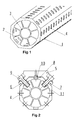
- an octagonal profile 1 is shown, in its interior stiffening ribs 2, which are supported on an inner hollow core 3.
- the linking element 5 has laterally arranged flanges. 6 and 7 on.
- the flanges 6 and 7 and the base 8 of the linking element 5 correspond to the octagonal profile 1. They comprise three sides of the Octagonal profile 1, wherein in the flanges 6 and 7 mounting screws 9 for Attach in the holes 4 serve.
- the holes 4 with Provided internal thread or it are introduced into the holes blind rivet nuts 11, which are held against rotation by suitable measures.
- the linking element 5 continues a centering pin 10 which in the enclosed hole 4 between the Screws 9 engages.
- the linking element 5 is repeatable and positively secure held.
- FIGS. 1 and 2 The arrangement shown in FIGS. 1 and 2 is particularly suitable for long hollow profiles, due to the stiffening ribs a high bending and torsional stiffness have low weight.
- blind rivet nuts 11 can also be inserted into the bores 4 become. Just as well, it is conceivable in the holes 4 threaded holes contribute.
Landscapes
- Engineering & Computer Science (AREA)
- Mechanical Engineering (AREA)
- Connection Of Plates (AREA)
- Lining And Supports For Tunnels (AREA)
- Clamps And Clips (AREA)
- Mutual Connection Of Rods And Tubes (AREA)
- Adornments (AREA)
- Vending Machines For Individual Products (AREA)
- Dowels (AREA)
- Insertion Pins And Rivets (AREA)
Abstract
Description
- Figur 1
- eine perspektivische Ansicht eines ersten Profils;
- Figur 2
- einen Querschnitt durch das Profil gemäß Figur 1;
- Figur 3
- eine zweite Ausführung des Profils;
- Figur 4
- einen Querschnitt durch die zweite Ausführung.
Claims (6)
- Elementsystem zum Aufbauen von Haltevorrichtungen für Werkstücke, bestehend aus einer Grundplatte und daran befestigbaren Profilen unterschiedlicher Länge, an denen Verknüpfungselemente befestigt werden,
dadurch gekennzeichnet, dass das Profil aus einem Vielkantprofil (Achtkantprofil 1) besteht, das auf seinem Umfang Bohrungen (4) zum Befestigen der Verknüpfungselemente (5) aufweist und dass jedes Verknüpfungselement (5) auf mindestens drei Seiten das Vielkantprofil umfasst. - Elementsystem nach Anspruch 1,
dadurch gekennzeichnet, dass das Vielkantprofil ein Achtkantprofil (1) ist. - Elementsystem nach Anspruch 1 oder 2,
dadurch gekennzeichnet, dass die Bohrungen (4) als Gewindebohrungen zum Befestigen der Verknüpfungselemente (5) ausgebildet sind. - Elementsystem nach Anspruch 1 oder 2,
dadurch gekennzeichnet, dass die Bohrungen (4) zur Aufnahme von Blindnietmuttern dienen. - Elementsystem nach einem der vorangegangenen Ansprüche,
dadurch gekennzeichnet, dass das Verknüpfungselement (5) einen Zentrierstift (10) aufweist, der zwischen den Befestigungselementen in eine Bohrung (4) eingreift. - Elementsystem nach einem der vorangegangenen Ansprüche,
dadurch gekennzeichnet, dass das Vielkantprofil in seinem Inneren Versteifungsrippen (2) aufweist.
Applications Claiming Priority (2)
| Application Number | Priority Date | Filing Date | Title |
|---|---|---|---|
| DE10353008 | 2003-11-13 | ||
| DE10353008A DE10353008A1 (de) | 2003-11-13 | 2003-11-13 | Elementsystem zum Aufbauen von Haltevorrichtungen |
Publications (2)
| Publication Number | Publication Date |
|---|---|
| EP1533072A1 true EP1533072A1 (de) | 2005-05-25 |
| EP1533072B1 EP1533072B1 (de) | 2009-03-04 |
Family
ID=34428715
Family Applications (1)
| Application Number | Title | Priority Date | Filing Date |
|---|---|---|---|
| EP04024359A Expired - Lifetime EP1533072B1 (de) | 2003-11-13 | 2004-10-13 | Elementsystem zum Aufbauen von Haltevorrichtungen |
Country Status (4)
| Country | Link |
|---|---|
| EP (1) | EP1533072B1 (de) |
| AT (1) | ATE424277T1 (de) |
| DE (2) | DE10353008A1 (de) |
| ES (1) | ES2319522T3 (de) |
Families Citing this family (5)
| Publication number | Priority date | Publication date | Assignee | Title |
|---|---|---|---|---|
| DE102011121584A1 (de) | 2011-12-16 | 2013-06-20 | Audi Ag | Modulares Tragsystem zur Fixierung von Bauteilen |
| DE102013006723A1 (de) | 2013-04-19 | 2014-10-23 | Springer Gmbh | Hohlprofilträger für eine Tragvorrichtung zum Tragen von Werkzeugen, Werkstücken oder dergleichen, System zum Aufbauen einer derartigen Tragvorrichtung sowie Kreuzverbinder und Vorrichtung zur Befestigung eines Endeffektors an einem Grundrahmen an einer derartigen Tragvorrichtung |
| DE102016123161A1 (de) * | 2016-11-30 | 2018-05-30 | Airbus Operations Gmbh | Aufsetzverbinder und System |
| DE102022204659A1 (de) | 2022-05-12 | 2023-11-16 | Springer Gmbh | Modular aufgebautes Tragsystem mit einer Traggrundstruktur aus Achtkantprofilen |
| DE102023115857A1 (de) | 2023-06-16 | 2024-12-19 | Thyssenkrupp Ag | Tragsystem und aus Formteilen gebildete Verbindungselemente eines Tragsystems |
Citations (5)
| Publication number | Priority date | Publication date | Assignee | Title |
|---|---|---|---|---|
| FR2543467A1 (fr) * | 1983-03-30 | 1984-10-05 | Ernault Somua H | Dispositif de changement d'outils dans une machine-outil a commande numerique |
| EP0310937A2 (de) * | 1987-10-09 | 1989-04-12 | Pehac Werkzeugmaschinen Gmbh | Spannkörper zur Befestigung von zu bearbeitenden Werkstücken |
| US5242043A (en) * | 1991-07-06 | 1993-09-07 | Giddings & Lewis Gmbh | Workpiece mounting pallet |
| DE29612937U1 (de) * | 1996-07-29 | 1996-09-05 | Horst Witte Entwicklungs- und Vertriebs-KG, 21369 Nahrendorf | Verbindungsrohr für Aufnahmeteile für ein System zum Aufbau von Vorrichtungen zum Aufspannen von Werkstücken |
| US6191983B1 (en) * | 1997-06-19 | 2001-02-20 | Hitachi, Ltd. | Semiconductor memory |
Family Cites Families (6)
| Publication number | Priority date | Publication date | Assignee | Title |
|---|---|---|---|---|
| DE3538034C1 (de) * | 1985-10-25 | 1986-09-25 | Bayerische Motoren Werke AG, 8000 München | Elementsystem zum Aufbau von Haltevorrichtungen fuer Werkstuecke |
| DE9216764U1 (de) * | 1992-12-09 | 1993-03-11 | Horst Witte Entwicklungs- und Vertriebs KG, 2122 Bleckede | Quaderförmiges Rohr für ein System zum Aufbau von Vorrichtungen zum Aufspannen von Werkstücken |
| DE29614657U1 (de) * | 1996-08-23 | 1996-11-14 | MERO GmbH & Co. KG, 97084 Würzburg | Profil zur Befestigung von vorzugsweise stab- oder trägerförmigen und/oder flächigen Bauelementen |
| US6098127A (en) * | 1998-06-26 | 2000-08-01 | Kwang; Yun-Ming | Interface socket for transmitting both signal transmission and power supply from motherboard to external peripheral |
| DE29905687U1 (de) * | 1999-03-27 | 1999-07-08 | DE-STA-CO Metallerzeugnisse GmbH, 61449 Steinbach | Trageinrichtung |
| DE20000695U1 (de) * | 2000-01-17 | 2000-06-29 | Schlagheck Design GmbH, 81539 München | Pendelleuchte |
-
2003
- 2003-11-13 DE DE10353008A patent/DE10353008A1/de not_active Withdrawn
-
2004
- 2004-10-13 DE DE502004009076T patent/DE502004009076D1/de not_active Expired - Lifetime
- 2004-10-13 EP EP04024359A patent/EP1533072B1/de not_active Expired - Lifetime
- 2004-10-13 ES ES04024359T patent/ES2319522T3/es not_active Expired - Lifetime
- 2004-10-13 AT AT04024359T patent/ATE424277T1/de not_active IP Right Cessation
Patent Citations (5)
| Publication number | Priority date | Publication date | Assignee | Title |
|---|---|---|---|---|
| FR2543467A1 (fr) * | 1983-03-30 | 1984-10-05 | Ernault Somua H | Dispositif de changement d'outils dans une machine-outil a commande numerique |
| EP0310937A2 (de) * | 1987-10-09 | 1989-04-12 | Pehac Werkzeugmaschinen Gmbh | Spannkörper zur Befestigung von zu bearbeitenden Werkstücken |
| US5242043A (en) * | 1991-07-06 | 1993-09-07 | Giddings & Lewis Gmbh | Workpiece mounting pallet |
| DE29612937U1 (de) * | 1996-07-29 | 1996-09-05 | Horst Witte Entwicklungs- und Vertriebs-KG, 21369 Nahrendorf | Verbindungsrohr für Aufnahmeteile für ein System zum Aufbau von Vorrichtungen zum Aufspannen von Werkstücken |
| US6191983B1 (en) * | 1997-06-19 | 2001-02-20 | Hitachi, Ltd. | Semiconductor memory |
Also Published As
| Publication number | Publication date |
|---|---|
| EP1533072B1 (de) | 2009-03-04 |
| ES2319522T3 (es) | 2009-05-08 |
| DE10353008A1 (de) | 2005-06-16 |
| ATE424277T1 (de) | 2009-03-15 |
| DE502004009076D1 (de) | 2009-04-16 |
Similar Documents
| Publication | Publication Date | Title |
|---|---|---|
| DE10018058B4 (de) | Montagehilfe für ein Federbein | |
| DE19912474C2 (de) | Befestigungsanordnung für die Anbringung eines Bauteils an einer C-förmigen Halteschiene | |
| DE3604030A1 (de) | Halteeinrichtung zur halterung eines elektrischen wandlers | |
| DE4200096C2 (de) | Vorrichtung zum Verschließen einer Öffnung in einer Verkleidung | |
| DE10021873B4 (de) | Elementsystem zum Aufbau von Halte- und/oder Messvorrichtungen | |
| EP1533072B1 (de) | Elementsystem zum Aufbauen von Haltevorrichtungen | |
| DE102018114830A1 (de) | Gaumenerweiterungsvorrichtung für eine kieferorthopädische Behandlung | |
| DE102011080118B4 (de) | Nullpunktspannstation | |
| DE19719915C2 (de) | Gabelglied für einen Leitwerkanschluß | |
| EP1332950B1 (de) | Vorrichtung zum Justieren der Einbaulage eines Mehrkomponentenmoduls in einem Kraftfahrzeug | |
| DE19543995A1 (de) | Verstellbares Stützlager, insbesondere oberes Federbein-Stützlager an einem Kraftfahrzeug | |
| DE19743873A1 (de) | Befestigung für eine vormontierte Baueinheit | |
| DE102018110924A1 (de) | Befestigungssystem | |
| DE19920521C2 (de) | Ausrichtvorrichtung zum Einpassen eines Kraftfahrzeugschweinwerfers in einen Karosserieausschnitt | |
| DE4430975C1 (de) | Vorrichtung mit einem gegen Herunterfallen an einem Körper gesicherten Befestigungselement | |
| EP2102038B1 (de) | Gehäuseanordnung einer wischeranlage mit schraubverbindung | |
| EP1593861B1 (de) | Verbindungselement | |
| DE102017114906B3 (de) | Sensorgehäuse zur Fixierung in verschiedenen C-Nutvarianten metallischer Befestigungskörper durch unterschiedliche Klemmflächenpaare | |
| EP3670957A1 (de) | Federpaket | |
| EP3344419B1 (de) | Drehmomentschrauber | |
| DE102014217781A1 (de) | Vorrichtung zum Befestigen eines Verkleidungselements | |
| DE102005007030B4 (de) | Rohrverbinder | |
| DE10107307A1 (de) | Flanschmitnehmer | |
| DE4317057C2 (de) | Vorrichtung zum Befestigen eines Federbeines, insbesondere eines Stoßdämpfers | |
| EP1388626A1 (de) | Halter |
Legal Events
| Date | Code | Title | Description |
|---|---|---|---|
| PUAI | Public reference made under article 153(3) epc to a published international application that has entered the european phase |
Free format text: ORIGINAL CODE: 0009012 |
|
| AK | Designated contracting states |
Kind code of ref document: A1 Designated state(s): AT BE BG CH CY CZ DE DK EE ES FI FR GB GR HU IE IT LI LU MC NL PL PT RO SE SI SK TR |
|
| AX | Request for extension of the european patent |
Extension state: AL HR LT LV MK |
|
| 17P | Request for examination filed |
Effective date: 20050607 |
|
| AKX | Designation fees paid |
Designated state(s): AT BE BG CH CY CZ DE DK EE ES FI FR GB GR HU IE IT LI LU MC NL PL PT RO SE SI SK TR |
|
| 17Q | First examination report despatched |
Effective date: 20070620 |
|
| GRAP | Despatch of communication of intention to grant a patent |
Free format text: ORIGINAL CODE: EPIDOSNIGR1 |
|
| GRAS | Grant fee paid |
Free format text: ORIGINAL CODE: EPIDOSNIGR3 |
|
| GRAA | (expected) grant |
Free format text: ORIGINAL CODE: 0009210 |
|
| AK | Designated contracting states |
Kind code of ref document: B1 Designated state(s): AT BE BG CH CY CZ DE DK EE ES FI FR GB GR HU IE IT LI LU MC NL PL PT RO SE SI SK TR |
|
| REG | Reference to a national code |
Ref country code: GB Ref legal event code: FG4D Free format text: NOT ENGLISH |
|
| REG | Reference to a national code |
Ref country code: CH Ref legal event code: EP |
|
| REG | Reference to a national code |
Ref country code: IE Ref legal event code: FG4D Free format text: LANGUAGE OF EP DOCUMENT: GERMAN |
|
| REF | Corresponds to: |
Ref document number: 502004009076 Country of ref document: DE Date of ref document: 20090416 Kind code of ref document: P |
|
| REG | Reference to a national code |
Ref country code: ES Ref legal event code: FG2A Ref document number: 2319522 Country of ref document: ES Kind code of ref document: T3 |
|
| PG25 | Lapsed in a contracting state [announced via postgrant information from national office to epo] |
Ref country code: NL Free format text: LAPSE BECAUSE OF FAILURE TO SUBMIT A TRANSLATION OF THE DESCRIPTION OR TO PAY THE FEE WITHIN THE PRESCRIBED TIME-LIMIT Effective date: 20090304 Ref country code: SI Free format text: LAPSE BECAUSE OF FAILURE TO SUBMIT A TRANSLATION OF THE DESCRIPTION OR TO PAY THE FEE WITHIN THE PRESCRIBED TIME-LIMIT Effective date: 20090304 Ref country code: FI Free format text: LAPSE BECAUSE OF FAILURE TO SUBMIT A TRANSLATION OF THE DESCRIPTION OR TO PAY THE FEE WITHIN THE PRESCRIBED TIME-LIMIT Effective date: 20090304 |
|
| NLV1 | Nl: lapsed or annulled due to failure to fulfill the requirements of art. 29p and 29m of the patents act | ||
| PG25 | Lapsed in a contracting state [announced via postgrant information from national office to epo] |
Ref country code: SE Free format text: LAPSE BECAUSE OF FAILURE TO SUBMIT A TRANSLATION OF THE DESCRIPTION OR TO PAY THE FEE WITHIN THE PRESCRIBED TIME-LIMIT Effective date: 20090604 Ref country code: PL Free format text: LAPSE BECAUSE OF FAILURE TO SUBMIT A TRANSLATION OF THE DESCRIPTION OR TO PAY THE FEE WITHIN THE PRESCRIBED TIME-LIMIT Effective date: 20090304 |
|
| REG | Reference to a national code |
Ref country code: IE Ref legal event code: FD4D |
|
| PG25 | Lapsed in a contracting state [announced via postgrant information from national office to epo] |
Ref country code: EE Free format text: LAPSE BECAUSE OF FAILURE TO SUBMIT A TRANSLATION OF THE DESCRIPTION OR TO PAY THE FEE WITHIN THE PRESCRIBED TIME-LIMIT Effective date: 20090304 Ref country code: IE Free format text: LAPSE BECAUSE OF FAILURE TO SUBMIT A TRANSLATION OF THE DESCRIPTION OR TO PAY THE FEE WITHIN THE PRESCRIBED TIME-LIMIT Effective date: 20090304 Ref country code: PT Free format text: LAPSE BECAUSE OF FAILURE TO SUBMIT A TRANSLATION OF THE DESCRIPTION OR TO PAY THE FEE WITHIN THE PRESCRIBED TIME-LIMIT Effective date: 20090819 |
|
| PG25 | Lapsed in a contracting state [announced via postgrant information from national office to epo] |
Ref country code: SK Free format text: LAPSE BECAUSE OF FAILURE TO SUBMIT A TRANSLATION OF THE DESCRIPTION OR TO PAY THE FEE WITHIN THE PRESCRIBED TIME-LIMIT Effective date: 20090304 Ref country code: RO Free format text: LAPSE BECAUSE OF FAILURE TO SUBMIT A TRANSLATION OF THE DESCRIPTION OR TO PAY THE FEE WITHIN THE PRESCRIBED TIME-LIMIT Effective date: 20090304 |
|
| PLBE | No opposition filed within time limit |
Free format text: ORIGINAL CODE: 0009261 |
|
| STAA | Information on the status of an ep patent application or granted ep patent |
Free format text: STATUS: NO OPPOSITION FILED WITHIN TIME LIMIT |
|
| PG25 | Lapsed in a contracting state [announced via postgrant information from national office to epo] |
Ref country code: BG Free format text: LAPSE BECAUSE OF FAILURE TO SUBMIT A TRANSLATION OF THE DESCRIPTION OR TO PAY THE FEE WITHIN THE PRESCRIBED TIME-LIMIT Effective date: 20090604 Ref country code: DK Free format text: LAPSE BECAUSE OF FAILURE TO SUBMIT A TRANSLATION OF THE DESCRIPTION OR TO PAY THE FEE WITHIN THE PRESCRIBED TIME-LIMIT Effective date: 20090304 |
|
| 26N | No opposition filed |
Effective date: 20091207 |
|
| BERE | Be: lapsed |
Owner name: BAYERISCHE MOTOREN WERKE A.G. Effective date: 20091031 |
|
| PG25 | Lapsed in a contracting state [announced via postgrant information from national office to epo] |
Ref country code: MC Free format text: LAPSE BECAUSE OF NON-PAYMENT OF DUE FEES Effective date: 20091031 |
|
| REG | Reference to a national code |
Ref country code: CH Ref legal event code: PL |
|
| PG25 | Lapsed in a contracting state [announced via postgrant information from national office to epo] |
Ref country code: GR Free format text: LAPSE BECAUSE OF FAILURE TO SUBMIT A TRANSLATION OF THE DESCRIPTION OR TO PAY THE FEE WITHIN THE PRESCRIBED TIME-LIMIT Effective date: 20090605 Ref country code: CH Free format text: LAPSE BECAUSE OF NON-PAYMENT OF DUE FEES Effective date: 20091031 Ref country code: LI Free format text: LAPSE BECAUSE OF NON-PAYMENT OF DUE FEES Effective date: 20091031 Ref country code: BE Free format text: LAPSE BECAUSE OF NON-PAYMENT OF DUE FEES Effective date: 20091031 |
|
| PG25 | Lapsed in a contracting state [announced via postgrant information from national office to epo] |
Ref country code: AT Free format text: LAPSE BECAUSE OF NON-PAYMENT OF DUE FEES Effective date: 20091013 |
|
| PG25 | Lapsed in a contracting state [announced via postgrant information from national office to epo] |
Ref country code: LU Free format text: LAPSE BECAUSE OF NON-PAYMENT OF DUE FEES Effective date: 20091013 |
|
| PG25 | Lapsed in a contracting state [announced via postgrant information from national office to epo] |
Ref country code: HU Free format text: LAPSE BECAUSE OF FAILURE TO SUBMIT A TRANSLATION OF THE DESCRIPTION OR TO PAY THE FEE WITHIN THE PRESCRIBED TIME-LIMIT Effective date: 20090905 |
|
| PG25 | Lapsed in a contracting state [announced via postgrant information from national office to epo] |
Ref country code: TR Free format text: LAPSE BECAUSE OF FAILURE TO SUBMIT A TRANSLATION OF THE DESCRIPTION OR TO PAY THE FEE WITHIN THE PRESCRIBED TIME-LIMIT Effective date: 20090304 |
|
| PG25 | Lapsed in a contracting state [announced via postgrant information from national office to epo] |
Ref country code: CY Free format text: LAPSE BECAUSE OF FAILURE TO SUBMIT A TRANSLATION OF THE DESCRIPTION OR TO PAY THE FEE WITHIN THE PRESCRIBED TIME-LIMIT Effective date: 20090304 |
|
| REG | Reference to a national code |
Ref country code: FR Ref legal event code: PLFP Year of fee payment: 12 |
|
| REG | Reference to a national code |
Ref country code: FR Ref legal event code: PLFP Year of fee payment: 13 |
|
| REG | Reference to a national code |
Ref country code: FR Ref legal event code: PLFP Year of fee payment: 14 |
|
| REG | Reference to a national code |
Ref country code: FR Ref legal event code: PLFP Year of fee payment: 15 |
|
| P01 | Opt-out of the competence of the unified patent court (upc) registered |
Effective date: 20230502 |
|
| PGFP | Annual fee paid to national office [announced via postgrant information from national office to epo] |
Ref country code: GB Payment date: 20231025 Year of fee payment: 20 |
|
| PGFP | Annual fee paid to national office [announced via postgrant information from national office to epo] |
Ref country code: ES Payment date: 20231117 Year of fee payment: 20 |
|
| PGFP | Annual fee paid to national office [announced via postgrant information from national office to epo] |
Ref country code: IT Payment date: 20231031 Year of fee payment: 20 Ref country code: FR Payment date: 20231023 Year of fee payment: 20 Ref country code: DE Payment date: 20231017 Year of fee payment: 20 Ref country code: CZ Payment date: 20231002 Year of fee payment: 20 |
|
| REG | Reference to a national code |
Ref country code: DE Ref legal event code: R071 Ref document number: 502004009076 Country of ref document: DE |
|
| PG25 | Lapsed in a contracting state [announced via postgrant information from national office to epo] |
Ref country code: CZ Free format text: LAPSE BECAUSE OF EXPIRATION OF PROTECTION Effective date: 20241013 |
|
| REG | Reference to a national code |
Ref country code: ES Ref legal event code: FD2A Effective date: 20241025 |
|
| PG25 | Lapsed in a contracting state [announced via postgrant information from national office to epo] |
Ref country code: CZ Free format text: LAPSE BECAUSE OF EXPIRATION OF PROTECTION Effective date: 20241013 |
|
| REG | Reference to a national code |
Ref country code: GB Ref legal event code: PE20 Expiry date: 20241012 |
|
| PG25 | Lapsed in a contracting state [announced via postgrant information from national office to epo] |
Ref country code: GB Free format text: LAPSE BECAUSE OF EXPIRATION OF PROTECTION Effective date: 20241012 |
|
| PG25 | Lapsed in a contracting state [announced via postgrant information from national office to epo] |
Ref country code: ES Free format text: LAPSE BECAUSE OF EXPIRATION OF PROTECTION Effective date: 20241014 |
|
| PG25 | Lapsed in a contracting state [announced via postgrant information from national office to epo] |
Ref country code: GB Free format text: LAPSE BECAUSE OF EXPIRATION OF PROTECTION Effective date: 20241012 Ref country code: ES Free format text: LAPSE BECAUSE OF EXPIRATION OF PROTECTION Effective date: 20241014 |