EP1533068B1 - Laserperforation - Google Patents
Laserperforation Download PDFInfo
- Publication number
- EP1533068B1 EP1533068B1 EP04026531A EP04026531A EP1533068B1 EP 1533068 B1 EP1533068 B1 EP 1533068B1 EP 04026531 A EP04026531 A EP 04026531A EP 04026531 A EP04026531 A EP 04026531A EP 1533068 B1 EP1533068 B1 EP 1533068B1
- Authority
- EP
- European Patent Office
- Prior art keywords
- rotation
- axis
- drum
- articles
- during
- Prior art date
- Legal status (The legal status is an assumption and is not a legal conclusion. Google has not performed a legal analysis and makes no representation as to the accuracy of the status listed.)
- Expired - Lifetime
Links
Images



Classifications
-
- B—PERFORMING OPERATIONS; TRANSPORTING
- B23—MACHINE TOOLS; METAL-WORKING NOT OTHERWISE PROVIDED FOR
- B23K—SOLDERING OR UNSOLDERING; WELDING; CLADDING OR PLATING BY SOLDERING OR WELDING; CUTTING BY APPLYING HEAT LOCALLY, e.g. FLAME CUTTING; WORKING BY LASER BEAM
- B23K26/00—Working by laser beam, e.g. welding, cutting or boring
- B23K26/02—Positioning or observing the workpiece, e.g. with respect to the point of impact; Aligning, aiming or focusing the laser beam
- B23K26/06—Shaping the laser beam, e.g. by masks or multi-focusing
- B23K26/067—Dividing the beam into multiple beams, e.g. multi-focusing
- B23K26/0676—Dividing the beam into multiple beams, e.g. multi-focusing into dependently operating sub-beams, e.g. an array of spots with fixed spatial relationship or for performing simultaneously identical operations
-
- A—HUMAN NECESSITIES
- A24—TOBACCO; CIGARS; CIGARETTES; SIMULATED SMOKING DEVICES; SMOKERS' REQUISITES
- A24C—MACHINES FOR MAKING CIGARS OR CIGARETTES
- A24C5/00—Making cigarettes; Making tipping materials for, or attaching filters or mouthpieces to, cigars or cigarettes
- A24C5/60—Final treatment of cigarettes, e.g. marking, printing, branding, decorating
- A24C5/606—Perforating cigarettes
-
- B—PERFORMING OPERATIONS; TRANSPORTING
- B23—MACHINE TOOLS; METAL-WORKING NOT OTHERWISE PROVIDED FOR
- B23K—SOLDERING OR UNSOLDERING; WELDING; CLADDING OR PLATING BY SOLDERING OR WELDING; CUTTING BY APPLYING HEAT LOCALLY, e.g. FLAME CUTTING; WORKING BY LASER BEAM
- B23K26/00—Working by laser beam, e.g. welding, cutting or boring
- B23K26/02—Positioning or observing the workpiece, e.g. with respect to the point of impact; Aligning, aiming or focusing the laser beam
- B23K26/06—Shaping the laser beam, e.g. by masks or multi-focusing
- B23K26/0604—Shaping the laser beam, e.g. by masks or multi-focusing by a combination of beams
-
- B—PERFORMING OPERATIONS; TRANSPORTING
- B23—MACHINE TOOLS; METAL-WORKING NOT OTHERWISE PROVIDED FOR
- B23K—SOLDERING OR UNSOLDERING; WELDING; CLADDING OR PLATING BY SOLDERING OR WELDING; CUTTING BY APPLYING HEAT LOCALLY, e.g. FLAME CUTTING; WORKING BY LASER BEAM
- B23K26/00—Working by laser beam, e.g. welding, cutting or boring
- B23K26/08—Devices involving relative movement between laser beam and workpiece
- B23K26/082—Scanning systems, i.e. devices involving movement of the laser beam relative to the laser head
- B23K26/0821—Scanning systems, i.e. devices involving movement of the laser beam relative to the laser head using multifaceted mirrors, e.g. polygonal mirror
-
- B—PERFORMING OPERATIONS; TRANSPORTING
- B23—MACHINE TOOLS; METAL-WORKING NOT OTHERWISE PROVIDED FOR
- B23K—SOLDERING OR UNSOLDERING; WELDING; CLADDING OR PLATING BY SOLDERING OR WELDING; CUTTING BY APPLYING HEAT LOCALLY, e.g. FLAME CUTTING; WORKING BY LASER BEAM
- B23K26/00—Working by laser beam, e.g. welding, cutting or boring
- B23K26/08—Devices involving relative movement between laser beam and workpiece
- B23K26/0823—Devices involving rotation of the workpiece
-
- B—PERFORMING OPERATIONS; TRANSPORTING
- B23—MACHINE TOOLS; METAL-WORKING NOT OTHERWISE PROVIDED FOR
- B23K—SOLDERING OR UNSOLDERING; WELDING; CLADDING OR PLATING BY SOLDERING OR WELDING; CUTTING BY APPLYING HEAT LOCALLY, e.g. FLAME CUTTING; WORKING BY LASER BEAM
- B23K26/00—Working by laser beam, e.g. welding, cutting or boring
- B23K26/36—Removing material
- B23K26/38—Removing material by boring or cutting
- B23K26/382—Removing material by boring or cutting by boring
-
- B—PERFORMING OPERATIONS; TRANSPORTING
- B23—MACHINE TOOLS; METAL-WORKING NOT OTHERWISE PROVIDED FOR
- B23K—SOLDERING OR UNSOLDERING; WELDING; CLADDING OR PLATING BY SOLDERING OR WELDING; CUTTING BY APPLYING HEAT LOCALLY, e.g. FLAME CUTTING; WORKING BY LASER BEAM
- B23K2103/00—Materials to be soldered, welded or cut
- B23K2103/30—Organic materials
- B23K2103/40—Paper
-
- B—PERFORMING OPERATIONS; TRANSPORTING
- B23—MACHINE TOOLS; METAL-WORKING NOT OTHERWISE PROVIDED FOR
- B23K—SOLDERING OR UNSOLDERING; WELDING; CLADDING OR PLATING BY SOLDERING OR WELDING; CUTTING BY APPLYING HEAT LOCALLY, e.g. FLAME CUTTING; WORKING BY LASER BEAM
- B23K2103/00—Materials to be soldered, welded or cut
- B23K2103/50—Inorganic materials other than metals or composite materials
Definitions
- the invention relates to a method and a device for perforation of rod-shaped articles of the tobacco-processing industry.
- ventilated cigarettes can be produced. These are cigarettes provided with a multiplicity of perforations in the area of their filter, which allow the smoker to inhale a certain amount of ambient air together with the tobacco smoke. This has the advantage of thinning the one hand inhaled tobacco smoke and on the other hand the advantage of reducing the smoking temperature and thus the nicotine and tar content in the smoke.
- the US 4,281,670 shows, for example, a method in which the cigarettes to be perforated for rolling about its longitudinal axis between the outer periphery of the conveyor roller carrying them and a corresponding concave outer surface of a stationary support block are rolled, the cigarettes already before passing through a passage opening in the support block passing laser beam rolled out of the arranged on the circumference of the rotating conveyor roller bearing points and are still rolled after passing the laser beam between the feed roller and the support block. Since this rolling must be carried out under sufficient contact pressure between the feed roller and the support block and the cigarettes have a very high throughput speed in view of today's high machine speeds in this area, there is an undesirable mechanical stress on the cigarettes.
- the DE 33 13 064 A1 a device in which the cigarettes are arranged in distributed over the outer circumference of a cylindrical roller troughs.
- the roller is driven by a hollow shaft, in which a further hollow shaft is rotatably mounted.
- This inner hollow shaft contains in a lying outside the outer shaft end portion of a beam splitter, and a downstream of this mirror, each associated with a focusing lens.
- These focusing lenses are arranged as well as the beam splitter and the mirror within the respective end portion of the inner hollow shaft.
- the arranged at the other end of the hollow shaft laser light source provides a pulsed laser beam, which extends within the inner hollow shaft.
- this pulsating laser beam at the other end of the inner hollow shaft divided into two partial beams, which are directed by a slot provided in the shaft on the exposed filter of a respective single cigarette.
- the inner hollow shaft rotates in the same direction, but at a higher frequency than the feed roller, so that the individual cigarettes each receive one hole in succession during one revolution of the inner hollow shaft.
- a disadvantage of this known device is that only single cigarettes can be perforated.
- a device for drilling holes in cigarettes in which a laser beam is fanned using a diverging lens to meet a plurality of converging lenses, each associated with a trough a number of rotatably arranged on a conveyor drum troughs.
- a device for perforating cigarettes or similar smoking article articles comprising a drum for conveying the cigarettes rotating about a rotation axis, carrying the cigarettes transversely axially on its circumference, in which a reflecting element for reflecting the beam onto a second reflecting element and from this to another reflective element is provided, the latter directing the beam in a direction parallel to the drum circumference and the beam is finally deflected by circularly suspended mirrors again outside the drum circumference in a direction substantially perpendicular to the drum periphery direction to the perforation of the article ,
- Object of the present invention is to improve methods and apparatus of the type mentioned.
- Embodiments of the invention in particular avoid the disadvantages of the aforementioned prior art.
- embodiments of the invention avoid rolling the cigarettes between a conveyor roller and a support block and / or the restriction to the perforation of single cigarettes.
- the invention includes the recognition that methods and devices of the type mentioned above must always be suitable for the perforation of double-filter cigarettes and this on economically rational way only by a perforation with the aid of an externally directed on a drum for conveying the articles directed high-energy beam is possible.
- the alignment means comprise a polygon mirror rotatable with its surfaces substantially through the axis of rotation of the drum and about an axis parallel to the axis of rotation of the drum for directing the beam outwards from the axis of rotation and for pivoting the beam about the axis of rotation, the polygon mirror being opposite the direction of rotation of the drum should be rotatable. In this way, the invention can be particularly reliable and easy to implement.
- At least one optical system is additionally provided for imaging the beam emerging from the axis of rotation, in which the focus of the optical system lies substantially on the line lying in the axis of rotation, the optical system having a second, preferably space-fixed, cylindrical lens for reshaping a pivoting movement of the beam.
- a focusing optics for focusing the deflected in the direction of the drum circumference beam is provided on at least one substantially spatially fixed focal point.
- the focal point is positioned in such a way that from the drum up its extent carried article transported through the focal point can be perforated by the jet a hole in the article.
- the second cylindrical lens and the focusing optics are designed and matched to one another such that at least two, preferably five, foci lying one behind the other in the direction of rotation of the drum can be generated by the parallel displacement of the beam by the focusing optics generated by the second cylindrical lens.
- the beam is switched off between the focal points.
- the rotational speeds of the polygonal mirror and drum, the circumference of the drum and the distance of the articles on the circumference of the drum and the number of facets of the polygon mirror are coordinated such that during a pivoting movement of the beam during the residence of the beam on a facet of the rotating polygon mirror, only the first, third, fifth, etc. articles are perforated in the angular range swept by the beam during this pivoting movement so that the respective articles following the perforated articles only during a subsequent pivoting movement on the subsequent facet of the Polygon mirror are perforable.
- the vote is such that the not perforated during the specific pivoting movement of the beam articles, at the earliest until the beginning of the subsequent pivoting movement, but at the latest when the article arrives under the focusing optics used for the directly leading article, under the previously focussed for the directly leading article active focusing optics, in turn, to be perforated.
- the tuning should be such that each article conveyed through the at least one stationary focal point of a focusing lens is perforated at this focal point.
- a rotating means may be provided for rotating the articles, preferably once, more preferably three times 360 °, about their longitudinal axis during the stay of the articles on the drum.
- These rotation means should be tuned to the other elements of the device such that the beam is pivoted about the axis of rotation by a certain angle, while by means of the rotation means the articles at least 360 ° around during their stay in the pivoting range of the beam corresponding to the given angle their longitudinal axis are rotatable, so that under each focusing optics, another peripheral portion of the article is perforated to eventually perforate the entire circumference of the article can.
- the beam used for perforation may have a i.w. circular or alternatively have an oval cross-section.
- FIG. 1 shows a schematic perspective view of a first embodiment 1 of a device according to the invention for the perforation of rod-shaped articles, here cigarettes 2, the tobacco processing industry.
- the device 1 has a rotatable about a rotation axis 4 in the counterclockwise direction, the cigarettes 2 transversely on its circumference carrying drum 6 for transversely axial conveying the cigarettes 2.
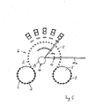
- the drum 6 is located between one in the Fig. 4 and 5 at the bottom right of the drum 6 shown ZuANCtrommel 5 for feeding the cigarettes 2 to the drum 6 and one in the Fig. 4 and 5 Bottom left of the drum 6 shown removal conveyor 7 for removing and conveying the cigarettes 2 from the drum. 6
- the device 1 furthermore has an alignment means designed as a polygon mirror 8 for aligning two energy-rich laser beams 10a and 10b suitable for perforation of the cigarettes 2 radially outward starting from the axis of rotation 4.
- the polygon mirror 8 has eight equally large facets 14 and is rotatable about an axis 16 parallel to the axis of rotation 4 of the drum 6.
- the axis 16 is arranged so that the facets 14 of the polygon mirror 8 are rotatable in the middle substantially through the axis of rotation 4 of the drum 6.
- the polygon mirror 8 is rotatable clockwise and thus counter to the direction of rotation of the drum 6.
- the two high-energy laser beams 10a and 10b suitable for perforating the cigarettes 2 can be generated by a CO 2 laser (not shown ) .
- the laser beams 10a, 10b are provided pulsed.
- the laser beam 10a is in the FIG. 1 shown in front, while the laser beam 10b in the FIG. 1 is shown lying behind.
- a first spatially fixed cylindrical lens 12 by means of which the beams 10 a, 10 b can be focused on a lying substantially in the axis of rotation 4 line.
- the facets 14 are rotatable by the focus of the first cylindrical lens 12.
- cylinder lenses 18a, 18b, 18c, 18d and 18e serving as optics for imaging the beams 10a and 10b emanating from the rotation axis 4 are arranged in an arcuate manner around the rotation axis 4 at the same distance from the rotation axis 4.
- the cylindrical lenses 18a to 18e are formed to deform a pivotal movement of the laser beams 10a, 10b about the rotation axis 4 caused by rotation of the polygon mirror 8 to a parallel displacement along the surfaces of the cylindrical lenses 18a to 18e.
- a caused by the facets 14 of the polygon mirror 8 pivoting range of the beams 10a, 10b from 90 ° here is covered by the cylindrical lenses 18a to 18d.
- Each cylindrical lens 18a to 18e is in turn associated with a first deflecting mirror 20a to 20e that is dimensionally stable and serves as the first deflecting means and is oriented at an angle of 45 ° to the circumference of the drum and is arranged outside the circumference of the drum.
- the beams 10a, 10b outside the drum circumference can be deflected in a direction substantially parallel to the drum circumference.
- Each first deflecting mirror 20a to 20e are in turn associated with space-fixed, second deflecting mirrors 22a to 22j, serving as second deflecting means and aligned at an angle of 45 ° to the drum circumference and arranged outside the drum circumference.
- the second deflecting mirrors 22a to 22e serve for deflecting the beam 10a in a direction substantially perpendicular to the drum circumference and the second deflecting mirrors 22f to 22j for deflecting the beam 10b in a direction substantially perpendicular to the drum circumference.
- spherical lenses 24 are arranged approximately parallel to the circumference of the drum as focusing optics for focusing a respective beam 10a, 10b deflected in the direction of the circumference of the drum.
- the spherical lenses 24 can focus the beams 10a, 10b at a substantially space fixed focal point.
- the spherical lenses 24 and thus their focus are designed and positioned in such a way that the cigarettes 2 carried by the drum 6 on their circumference can be conveyed through the focal point generated by the spherical lenses 24 such that one or each of the beams 10a, 10b several holes in the cigarettes is perforable.
- the operation of the device 1 is as follows:
- the laser beams 10a and 10b are generated by the CO 2 laser and directed to the first space-fixed cylindrical lens 12, which focuses the laser beams 10 a, 10 b on the substantially lying in the axis of rotation 4 line.
- the polygon mirror 8 with its facet 14 lying in the focus of the cylindrical lens 12 at this time, throws the facet 14 onto this facet 14 incident laser beams 10a and 10b on one of the five cylindrical lenses 18a, 18b, 18c, 18d and 18e. In the Fig. 1 this is the lens 18b.
- the cylindrical lenses 18a to 18e, in the Fig. 1 If this is the lens 18b, the pivotal movement of the laser beams 10a, 10b caused by the rotation of the polygon mirror 8 forms about the rotation axis 4 in a parallel displacement along the surfaces of the cylindrical lenses 18a through 18e, in FIG Fig. 1 this is the lens 18b to.
- the rotational speed of the polygon mirror 8 and thus the movement of the beams 10a, 10b through the respective cylindrical lenses 18a to 18e are tuned to the on / off frequency of the pulsed beams 10a and 10b such that the beams 10a, 10b move during their pivoting through one of the Cylinder lenses 18a to 18e through several times, can be turned on in the example shown five times for a period of time that is sufficient to introduce a perforation in the cigarette 2.
- the laser and thus the beams 10a, 10b are switched off.
- each of the facets 14 pivots the beams 10a and 10b by 90 ° clockwise while the beams 10a and 10b are on this facet 14.
- the first deflecting mirrors 20a to 20e deflect the beams 10a, 10b outside the circumference of the drum in a direction substantially parallel to the drum circumference. Subsequently, the beam 10a from the second deflecting mirrors 22a to 22e, in the Fig. 1 the mirror 22b, and the second laser beam 10b from the second deflecting mirrors 22f to 22j, in FIG Fig. 1 the mirror 22g, deflected in a direction substantially perpendicular to the drum circumference direction.
- the laser beams 10a and 10b thus deflected perpendicular to the drum periphery are focused by the lenses 24 on the peripheral surfaces 2a of the cigarettes 2 rotating on the drum 6 to perforate the peripheral surfaces 2a.
- FIG. 1 shows by way of example the situation in which the laser beams 10a, 10b are focused by the polygon mirror 8 on the cylindrical lens 18b, from there to the deflection mirror 20b and from there to the deflection mirrors 22b and 22g and from these to the spherical lenses 24.
- the angle of incidence of the laser beams 10a, 10b on one of the eight facets 14 of the polygon mirror 8 changes such that the laser beams 10a, 10b through 90 ° around the axis of rotation 4 through all cylindrical lenses 18a to 18e and thus also be swiveled through all deflecting mirrors 20a to 20e, through all the second deflecting mirrors 22a to 22j and also through all the focusing lenses 24, and thus gradually perforate all cigarettes 2 conveyed under the focusing lenses 24.
- FIG. 2 shows in close-up the area of the second deflection mirrors 22a to 22j.
- the laser beams 10a, 10b are in a clockwise direction due to advanced rotation of the polygon mirror 8 FIG. 1 represented more advanced pivoted position in which they pass through in the FIG. 2 not shown cylindrical lens 18c on the also in the FIG. 2
- Deflection mirror 20c, not shown are directed onto the deflection mirrors 22c (beam 10a) and 22h (beam 10b) and focused from there via the lenses 24c (beam 10a) and 24h (beam 10b) onto the peripheral surface 2a of a cigarette 2, around the peripheral surface 2a to perforate.
- FIG. 3 shows a side view of the device 1 of FIG. 1 in the in the FIG. 2 illustrated situation.
- FIG. 4 shows a front view of the device 1 of FIG. 1 in the in the FIG. 1 illustrated situation.
- FIG. 5 shows one opposite the FIG. 2 more advanced state, in which the polygon mirror 8 is rotated even further in a clockwise direction, so that the laser beams 10a, 10b have come to the edge of that facet 14, with which they from the in the FIGS. 1 or 4 position shown in the FIG. 2 shown position and finally on the FIG. 5 shown position were pivoted.
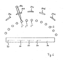
- FIGS. 6 and 7 each show in its upper part a schematic representation of the promoted on the drum circumference of the drum 6 cigarettes 2 and a schematic representation of the lenses 24 and the beam 10a.
- the peripheral surface 2a of a cigarette 2 ' which has just been processed by the beam 10a, in the unwound state, together with holes 30 which have already been perforated into the cigarette 2 in this peripheral surface 2a, is shown.
- FIG. 6 is the one in the FIGS. 1 and 4 illustrated pivot angle of the beam 10a on the cylindrical lens 18b, the deflecting mirror 20b, the second deflecting mirror 22b and thus to this second deflecting mirror 22b associated lens 24b shown.
- the article 2 'currently located at this point has already passed the foci of the lenses 24e to 24c associated with the deflecting mirrors 22e, 22d and 22c. Due to the parallel displacement of the laser beam 10a turned on during the pivoting on a cylindrical lens 18e, 18d and 18c by the cylindrical lenses 18e, 18d and 18c, the peripheral surface 2a of the article 2 'has five each during each stay under one of the lenses 24e, 24d and 24c Holes 30 get perforated.
- the article 2 ' is now below the fourth in the conveying or rotation direction of the drum 6 focusing lens 24b.
- the laser beam 10a is also at this position. Because the rotational speed of the drum 6, the rotational speed of the polygon mirror 8, the number of facets 14 on the polygon mirror 8, the distance of the cigarettes 2 on the circumference of the drum 6 and the circumference of the drum 6 are coordinated so that always a cigarette. 2 under a lens 24a, 24b, 24c, 24d, 24e when the beam 10a is on this lens 24a, 24b, 24c, 24d, 24e.
- the rotational speed of the drum 6, the rotational speed of the polygon mirror 8, the number of facets 14 on the polygon mirror 8, the distance of the cigarettes 2 on the circumference of the drum 6 and the circumference of the drum 6 are coordinated so that each cigarette. 2 under each lens 24a, 24b, 24c, 24d, 24e once, so here a total of five times with five individual holes 30 is perforated.
- FIG. 6 has caused by the polygon mirror 8 pivotal movement of the laser beam 10a in the region of the cylindrical lens 18b, which was converted by the cylindrical lens 18b in a parallel displacement, already to three holes 30 in a portion of the peripheral surface 2a of the article 2 '.
- the laser beam 10a is now moved by the pivoting movement of the polygon mirror 8 and the transformation of this pivotal movement in a parallel displacement by the cylindrical lens 18b further to the right on the lens 24b and is in this way two more holes to the right of the three on the peripheral surface 2a shown Holes 30 in the peripheral surface 2a of the article 2 'perforate.
- the article 2 'passes outside the area of the lens 24b.
- the laser beam 10a leaves in the FIG. 6 shown lens 24b and is further pivoted by the polygon mirror 8 in the clockwise subsequent thereto lens 24c at which he will perforate the then directly under the lens 24 promoted Article 2 ".
- the laser 10a has already been pivoted clockwise by the polygon mirror 8 as far as the lens 24e, has reached the next facet 14 of the polygon mirror 8 and thus in the - off state - have been pivoted back counterclockwise to its on the lens 24a leftmost starting position, has been moved from the cylindrical lens 18a on the lens 24a in a clockwise direction to a far right on the lens 24a lying position and to change from the rightmost position on lens 24a has been turned off and on again to the leftmost position of lens 24b.
- the article 2 "' is then perforated by the laser 10a via the lens 24b. In this way, each of the articles 2 in the area of each of the lenses 24a to 24e is perforated with a hole 30 five times at a time.
- the cigarettes 2 are rotatably mounted on the circumference. For example, this can be done in one of the DE 3510119 C2 or in the DE 3313064 C2 revealed manner happen.
- the cigarettes 2 By the rotation of the cigarettes 2 on the circumference of the drum 6, it is ensured that the cigarettes 2 under each lens 24a, 24b, 24c, 24d, 24e are perforated at another portion.
- a perforation pattern uniformly provided with holes 30 results on the entire peripheral surface 2a of the articles 2. This is evident from the illustration of FIGS Circumferential surface 2a below in the FIGS. 6 and 7 ,
- FIG. 7 shows a state in which the article 2 'is perforated with its peripheral surface 2a almost completely with holes 30 on its peripheral surface 2a.
- the in the FIG. 7 The position shown shows the position of the laser 10 a rightmost on the lens 24 a immediately before the introduction of the last rightmost on the peripheral surface 2 a of FIG. 7 missing hole 30 in the cigarette 2 '.
Landscapes
- Physics & Mathematics (AREA)
- Optics & Photonics (AREA)
- Engineering & Computer Science (AREA)
- Plasma & Fusion (AREA)
- Mechanical Engineering (AREA)
- Manufacturing Of Cigar And Cigarette Tobacco (AREA)
- Laser Beam Processing (AREA)
- Laser Surgery Devices (AREA)
- Glass Compositions (AREA)
- Materials For Medical Uses (AREA)
Description
- Die Erfindung betrifft ein Verfahren und eine Vorrichtung zur Perforation von stabförmigen Artikeln der tabakverarbeitenden Industrie.
- Unter stabförmigen Artikeln der tabakverarbeitenden Industrie werden hier insbesondere Einzelzigaretten, Doppelfilterzigaretten, Zigarettenfilter oder Tabakstöcke für Zigaretten, bspw. Tabakstöcke aus Schnitttabak, verstanden.
- Die eingangs genannten Verfahren und Vorrichtungen sind aus dem Stand der Technik bekannt. Mit solchen Verfahren und Vorrichtungen können beispielsweise sogenannte belüftete Zigaretten erzeugt werden. Dies sind Zigaretten, die im Bereich ihres Filters mit einer Vielzahl von Perforationen versehen sind, die es dem Raucher gestatten, zusammen mit dem Tabakrauch einen gewissen Anteil von Umgebungsluft zu inhalieren. Dies hat zum einen den Vorteil des Verdünnens des inhalierten Tabakrauchs und zum anderen den Vorteil der Reduzierung der Rauchtemperatur und somit des Nikotin- und Teergehalts im Rauch.
- Die
US 4,281,670 zeigt beispielsweise ein Verfahren, bei dem die zu perforierenden Zigaretten zum Drehen um ihre Längsachse zwischen dem Außenumfang der sie tragenden Förderwalze und einer entsprechend konkav verlaufenden Außenfläche eines stationären Stützblockes abgerollt werden, wobei die Zigaretten bereits vor dem Passieren des durch eine Durchtrittsöffnung im Stützblock hindurchtretenden Laserstrahlbündels aus dem am Umfang der umlaufenden Förderwalze angeordneten Auflagerstellen herausgerollt und auch nach dem Passieren des Laserstrahlenbündels noch zwischen der Förderwalze und dem Stützblock gerollt werden. Da dieses Rollen unter hinreichendem Anpressdruck zwischen der Förderwalze und dem Stützblock erfolgen muss und die Zigaretten angesichts der heutigen hohen Maschinengeschwindigkeiten in diesem Bereich eine sehr hohe Durchlaufgeschwindigkeit aufweisen, kommt es zu einer unerwünschten mechanischen Strapazierung der Zigaretten. - Es existieren daher Vorrichtungen, die diese Strapazen zu vermeiden suchen. So zeigt beispielsweise die
DE 33 13 064 A1 eine Vorrichtung, bei der die Zigaretten in über den Außenumfang einer zylindrischen Walze verteilten Mulden angeordnet sind. Die Walze ist über eine Hohlwelle angetrieben, in der eine weitere Hohlwelle drehbar gelagert ist. Diese innere Hohlwelle enthält in einem außerhalb der Außenwelle liegenden Endabschnitt einen Strahlenteiler, sowie einem diesen nachgeordneten Spiegel, denen jeweils eine Fokussierlinse zugeordnet ist. Diese Fokussierlinsen sind ebenso wie der Strahlenteiler und der Spiegel innerhalb des betreffenden Endabschnittes der inneren Hohlwelle angeordnet. Die am anderen Ende der Hohlwellen angeordnete Laserlichtquelle liefert einen pulsierenden Laserstrahl, der innerhalb der inneren Hohlwelle verläuft. Durch den Strahlenteiler und den Spiegel wird dieser pulsierende Laserstrahl am anderen Ende der inneren Hohlwelle in zwei Teilstrahlen aufgeteilt, die durch einen in der Welle vorgesehenen Schlitz auf den freiliegenden Filter einer jeweiligen Einzelzigarette gerichtet werden. Die innere Hohlwelle dreht dabei in gleicher Richtung, aber mit einer höheren Frequenz als die Förderwalze, so dass die Einzelzigaretten während einer Umdrehung der inneren Hohlwelle jeweils nacheinander jeweils ein Loch erhalten. - Nachteilig bei dieser bekannten Vorrichtung ist es jedoch, dass nur Einzelzigaretten perforiert werden können.
- Der gleiche Nachteil ist bei einer aus der
DE 35 101 19 C2 bekannten Vorrichtung der eingangs genannten Art zu beobachten. Aus dieser Druckschrift ist eine Vorrichtung zum Bohren von Löchern in Zigaretten bekannt, bei der ein Laserstrahl mit Hilfe einer Streulinse aufgefächert wird, um eine Mehrzahl von Sammellinsen zu treffen, die jeweils einer Mulde einer Anzahl von auf einer Fördertrommel drehbar angeordneten Mulden zugeordnet sind. - Aus der
US 4.585.919 ist eine Vorrichtung zur Perforation von Zigaretten oder ähnlichen Rauchwarenartikeln bekannt, bei der eine um eine Rotationsachse rotierende, die Zigaretten quer axial auf ihrem Umfang tragende Trommel zum Fördern der Zigaretten vorgesehen ist, bei der ein reflektierendes Element zum Reflektieren des Strahls auf ein zweites reflektierendes Element und von diesem auf ein weiteres reflektierendes Element vorgesehen ist, wobei letzteres den Strahl in eine parallel zum Trommelumfang verlaufende Richtung lenkt und der Strahl schließlich von kreisförmig aufgehängten Spiegeln erneut außerhalb des Trommelumfangs in eine im wesentlichen senkrecht zum Trommelumfang verlaufende Richtung zur Perforation der Artikel umgelenkt wird. - Aufgabe der vorliegenden Erfindung ist es, Verfahren und Vorrichtungen der eingangs genannten Art zu verbessern.
- Diese Aufgabe wird erfindungsgemäß durch ein Verfahren gemäß Anspruch 1 und durch eine Vorrichtung gemäß Anspruch 20 gelöst.
- Ausführungsformen der Erfindung vermeiden insbesondere die Nachteile des vorstehend genannten Standes der Technik. So vermeiden Ausführungsformen der Erfindung das Rollen der Zigaretten zwischen einer Förderwalze und einem Stützblock und/oder die Beschränkung auf die Perforation von Einzelzigaretten.
- Die Erfindung schließt die Erkenntnis ein, dass Verfahren und Vorrichtungen der eingangs genannten Art immer auch zur Perforation von Doppelfilterzigaretten geeignet sein müssen und dies auf wirtschaftlich vernünftige Weise nur durch eine Perforation mit Hilfe eines von außen auf eine Trommel zum Fördern der Artikel gerichteten energiereichen Strahls möglich ist.
- Bevorzugt sind Mittel vorgesehen, die den Strahl im wesentlichen senkrecht zur Rotationsachse zur Verfügung stellen. Weiter bevorzugt weisen die Mittel eine erste, vorteilhaft raumfeste, Zylinderlinse auf, die den Strahl auf eine im wesentlichen in der Rotationsachse liegende Linie fokussiert. Erfindungsgemäß weisen die Ausrichtmittel einen mit seinen Oberflächen im wesentlichen durch die Rotationsachse der Trommel und um eine zur Rotationsachse der Trommel parallele Achse rotierbaren Polygonspiegel zum Ausrichten des Strahls von der Rotationsachse ausgehend nach außen und zum Verschwenken des Strahls um die Rotationsachse auf, wobei der Polygonspiegel entgegen der Rotationsrichtung der Trommel rotierbar sein sollte. Auf diese Weise lässt sich die Erfindung besonders zuverlässig und einfach verwirklichen.
- Erfindungsgemäß ist zusätzlich mindestens eine Optik zum Abbilden des von der Rotationsachse ausgehenden Strahls vorgesehen, bei der der Fokus der Optik im wesentlichen auf der in der Rotationsachse liegenden Linie liegt, wobei die Optik eine zweite, bevorzugt raumfeste, Zylinderlinse aufweist zum Umformen einer Schwenkbewegung des Strahls um die Rotationsachse in eine Parallelverschiebung des Strahls, Dadurch wird vorteilhaft sichergestellt, dass die Strahleigenschaften des Strahls, wie beispielsweise Zweireihigkeit des Strahls, Strahldurchmesser und Polarisation, erhalten bleiben.
- Bei der Erfindung ist eine Fokussieroptik zum Fokussieren des in Richtung auf den Trommelumfang umgelenkten Strahls auf mindestens einen im wesentlichen raumfesten Brennpunkt vorgesehen. Der Brennpunkt ist dabei derart positioniert, dass die von der Trommel auf ihrem Umfang getragenen Artikel derart durch den Brennpunkt hindurchgefördert werden können, dass von dem Strahl ein Loch in die Artikel perforierbar ist. Die zweite Zylinderlinse und die Fokussieroptik sind erfindungsgemäß derart ausgebildet und aufeinander abgestimmt, dass durch die von der zweiten Zylinderlinse erzeugte Parallelverschiebung des Strahls von der Fokussieroptik mindestens zwei, bevorzugt fünf, in Rotationsrichtung der Trommel hintereinander liegende Brennpunkte erzeugbar sind. Vorteilhafterweise wird der Strahl zwischen den Brennpunkten abgeschaltet.
- Von Vorteil ist auch, wenn die Rotationsgeschwindigkeiten von Polygonspiegel und Trommel, der Umfang der Trommel und der Abstand der Artikel auf dem Umfang der Trommel und die Anzahl der Facetten des Polygonspiegels derart aufeinander abgestimmt sind, dass während einer Verschwenkbewegung des Strahls während des Aufenthalts des Strahls auf einer Facette des rotierenden Polygonspiegels nur der erste, dritte, fünfte, usw. Artikel in dem während dieser Verschwenkbewegung von dem Strahl überstrichenen Winkelbereich perforiert wird, so dass die auf die perforierten Artikel jeweils nachfolgenden Artikel erst während einer darauffolgenden Verschwenkbewegung auf der darauffolgenden Facette des Polygonspiegels perforierbar sind.
- Dabei sollte sichergestellt sein, dass die Abstimmung derart ist, dass die während der bestimmten Verschwenkbewegung des Strahls nicht perforierten Artikel, frühestens bis zum Beginn der darauffolgenden Verschwenkbewegung, jedoch spätestens beim Eintreffen des Artikels unter der für den direkt vorauseilenden Artikel verwendeten Fokussieroptik, unter jeweils die zuvor für den direkt vorauseilenden Artikel aktiven Fokussieroptiken gefördert werden, um ihrerseits perforiert zu werden.
- Die Abstimmung sollte so sein, dass jeder durch den mindestens einen raumfesten Brennpunkt einer Fokussieroptik hindurch geförderte Artikel an diesem Brennpunkt perforiert wird.
- Um die Artikel auf ihrem Umfang gleichmäßig zu perforieren, kann ein Rotationsmittel zum Rotieren der Artikel, bevorzugt einmal, weiter bevorzugt dreimal um 360°, um ihre Längsachse während des Aufenthalts der Artikel auf der Trommel vorgesehen werden. Diese Rotationsmittel sollten so auf die anderen Elemente der Vorrichtung abgestimmt werden, dass der Strahl um die Rotationsachse um einen bestimmten Winkel verschwenkt wird, während mit Hilfe der Rotationsmittel die Artikel während ihres Aufenthalts in dem dem bestimmten Winkel entsprechenden Verschwenkbereich des Strahls mindestens um 360° um ihre Längsachse rotierbar sind, so dass unter jeder Fokussieroptik ein anderer Umfangsabschnitt der Artikel perforierbar ist, um schließlich den gesamten Umfang des Artikels perforieren zu können.
- Der zum Perforieren verwendete Strahl kann einen i.w. kreisförmigen oder alternativ einen ovalen Querschnitt aufweisen.
- Weitere bevorzugte Ausführungsformen der Erfindung sind in den Unteransprüchen angegeben.
- Ein bevorzugtes Ausführungsbeispiel der Erfindung wird nun anhand der begleitenden Zeichnungen beschrieben. Die Zeichnungen zeigen:
- Figur 1
- eine schematische perspektivische Ansicht einer Ausführungsform einer erfindungsgemäßen Vorrichtung;
- Figur 2
- ein Detail der Ausführungsform der
Figur 1 ; - Figur 3
- die Ausführungsform der
Figur 1 in einer Seitenansicht; - Figur 4
- eine Vorderansicht der Ausführungsform der
Figur 1 ; - Figur 5
- die Ansicht der
Figur 4 bei weiter rotiertem Polygonspiegel; - Figur 6
- eine schematische Darstellung der Funktionsweise der Ausführungsform der
Figur 1 ; und - Figur 7
- die schematische Darstellung der
Figur 6 in fortgeschrittenem Zustand. -
Figur 1 zeigt eine schematische perspektivische Ansicht einer ersten Ausführungsform 1 einer erfindungsgemäßen Vorrichtung zur Perforation von stabförmigen Artikeln, hier Zigaretten 2, der tabakverarbeitenden Industrie. - Die Vorrichtung 1 weist eine um eine Rotationsachse 4 im Gegenuhrzeigersinn rotierbare, die Zigaretten 2 queraxial auf ihrem Umfang tragende Trommel 6 zum queraxialen Fördern der Zigaretten 2 auf. Die Trommel 6 liegt zwischen einer in den
Fig. 4 und5 rechts unten von der Trommel 6 dargestellten Zufördertrommel 5 zum Zufördern der Zigaretten 2 zu der Trommel 6 und einer in denFig. 4 und5 links unten von der Trommel 6 dargestellten Abfördertrommel 7 zum Abnehmen und Abfördern der Zigaretten 2 von der Trommel 6. - Die Vorrichtung 1 weist weiterhin ein als Polygonspiegel 8 ausgebildetes Ausrichtmittel zum Ausrichten von zwei zur Perforation der Zigaretten 2 geeigneten energiereichen Laserstrahlen 10a und 10b von der Rotationsachse 4 ausgehend radial nach außen auf. Zu diesem Zweck weist der Polygonspiegel 8 acht gleich große Facetten 14 auf und ist um eine zur Rotationsachse 4 der Trommel 6 parallele Achse 16 rotierbar. Dabei ist die Achse 16 so angeordnet, dass die Facetten 14 des Polygonspiegels 8 im Mittel im wesentlichen durch die Rotationsachse 4 der Trommel 6 rotierbar sind. Der Polygonspiegel 8 ist im Uhrzeigersinn und somit entgegen der Rotationsrichtung der Trommel 6 rotierbar.
- Die zwei zur Perforation der Zigaretten 2 geeigneten energiereichen Laserstrahlen 10a und 10b sind von einem nicht dargestellten CO2-Laser erzeugbar. Die Laserstrahlen 10a, 10b werden gepulst zur Verfügung gestellt. Der Laserstrahl 10a ist in der
Figur 1 vorne dargestellt, während der Laserstrahl 10b in derFigur 1 hinten liegend dargestellt ist. - Zwischen dem CO2-Laser und dem Polygonspiegel 8 befindet sich im Strahlengang des Strahlen 10a, 10b eine erste raumfest angeordnete Zylinderlinse 12, mit deren Hilfe die Strahlen 10a, 10b auf eine im wesentlichen in der Rotationsachse 4 liegende Linie fokussierbar sind. Somit sind die Facetten 14 durch den Fokus der ersten Zylinderlinse 12 rotierbar.
- Fünf als Optiken zum Abbilden der von der Rotationsachse 4 ausgehenden Strahlen 10a und 10b dienende Zylinderlinsen 18a, 18b, 18c, 18d und 18e sind nebeneinander bogenförmig um die Rotationsachse 4 herum in gleichem Abstand zur Rotationsachse 4 angeordnet. Die Zylinderlinsen 18a bis 18e sind so ausgebildet, dass sie eine durch eine Rotation des Polygonspiegels 8 verursachte Schwenkbewegung der Laserstrahlen 10a, 10b um die Rotationsachse 4 in eine Parallelverschiebung entlang der Oberflächen der Zylinderlinsen 18a bis 18e umformen. Ein durch die Facetten 14 des Polygonspiegels 8 verursachter Verschwenkbereich der Strahlen 10a, 10b von hier 90° wird durch die Zylinderlinsen 18a bis 18d abgedeckt.
- Jeder Zylinderlinse 18a bis 18e ist wiederum ein raumfester, als erstes Umlenkmittel dienender und jeweils im 45° Winkel zum Trommelumfang ausgerichteter und außerhalb des Trommelumfangs angeordneter erster Umlenkspiegel 20a bis 20e zugeordnet. Mit diesen Umlenkspiegeln 20a bis 20e können die Strahlen 10a, 10b außerhalb des Trommelumfangs in eine im wesentlichen parallel zum Trommelumfang verlaufende Richtung umgelenkt werden.
- Jedem ersten Umlenkspiegel 20a bis 20e sind wiederum raumfeste, als zweite Umlenkmittel dienende und jeweils im 45° Winkel zum Trommelumfang ausgerichtete und außerhalb des Trommelumfangs angeordnete zweiter Umlenkspiegel 22a bis 22j zugeordnet. Dabei dienen die zweiten Umlenkspiegel 22a bis 22e zum Umlenken des Strahls 10a in eine im wesentlichen senkrecht zum Trommelumfang verlaufende Richtung und die zweiten Umlenkspiegel 22f bis 22j zum Umlenken des Strahls 10b in eine im wesentlichen senkrecht zum Trommelumfang verlaufende Richtung.
- Senkrecht zwischen den zweiten Umlenkspiegeln 22a bis 22j und dem Trommelumfang sind als Fokussieroptik zum Fokussieren eines jeweils in Richtung auf den Trommelumfang umgelenkten Strahls 10a, 10b sphärische Linsen 24 in etwa parallel zum Trommelumfang angeordnet. Die sphärischen Linsen 24 können die Strahlen 10a, 10b auf einen im wesentlichen raumfesten Brennpunkt fokussieren. Die sphärischen Linsen 24 und damit ihr Fokus sind dabei derart ausgebildet und positioniert, dass die von Trommel 6 auf ihrem Umfang getragenen Zigaretten 2 derart durch den von den sphärischen Linsen 24 erzeugten Brennpunkt hindurch förderbar sind, dass von den Strahlen 10a, 10b jeweils ein oder mehrere Löcher in die Zigaretten perforierbar ist.
- Die Funktionsweise der Vorrichtung 1 ist wie folgt:
- Die Laserstrahlen 10a und 10b werden von dem CO2-Laser erzeugt und auf die erste raumfeste Zylinderlinse 12 gerichtet, die die Laserstrahlen 10a, 10b auf die im wesentlichen in der Rotationsachse 4 liegende Linie fokussiert.
- Der Polygonspiegel 8 wirft mit seiner zu diesem Zeitpunkt im Fokus der Zylinderlinse 12 liegenden Facette 14 die auf diese Facette 14 auftreffenden Laserstrahlen 10a und 10b auf eine der fünf Zylinderlinsen 18a, 18b, 18c, 18d und 18e. In der
Fig. 1 ist dies die Linse 18b. - Die Zylinderlinsen 18a bis 18e, in der
Fig. 1 ist dies die Linse 18b, formen die durch die Rotation des Polygonspiegels 8 verursachte Schwenkbewegung der Laserstrahlen 10a, 10b um die Rotationsachse 4 herum in eine Parallelverschiebung entlang der Oberflächen der Zylinderlinsen 18a bis 18e, in derFig. 1 ist dies die Linse 18b, um. Die Rotationsgeschwindigkeit des Polygonspiegels 8 und damit die Bewegung der Strahlen 10a, 10b durch die jeweiligen Zylinderlinsen 18a bis 18e hindurch sind so auf die Ein-/Ausschaltfrequenz der gepulsten Strahlen 10a und 10b abgestimmt, dass die Strahlen 10a, 10b während ihres Verschwenkens durch eine der Zylinderlinsen 18a bis 18e hindurch mehrfach, im dargestellten Beispiel fünfmal für eine Zeitdauer eingeschaltet werden können, die zum Einbringen einer Perforation in die Zigaretten 2 ausreichend ist. Während des Übergangs von einer Zylinderlinse 18a bis 18e zur nächsten wird der Laser und damit die Strahlen 10a, 10b ausgeschaltet. - Da der Polygonspiegel 8 insgesamt acht Facetten 14 aufweist, verschwenkt während der Rotation des Polygonspiegels 8 jede der Facetten 14 die Strahlen 10a und 10b um jeweils 90° im Uhrzeigersinn während die Strahlen 10a und 10b sich auf dieser Facette 14 befinden.
- Die ersten Umlenkspiegel 20a bis 20e lenken die Strahlen 10a, 10b außerhalb des Trommelumfangs in eine im wesentlichen parallel zum Trommelumfang verlaufende Richtung um. Anschließend wird der Strahl 10a von den zweiten Umlenkspiegeln 22a bis 22e, in der
Fig. 1 der Spiegel 22b, und der zweite Laserstrahl 10b von den zweiten Umlenkspiegeln 22f bis 22j, in derFig. 1 der Spiegel 22g, in eine im wesentlichen senkrecht zum Trommelumfang verlaufende Richtung umgelenkt. - Anschließend werden die so senkrecht auf den Trommelumfang umgelenkten Laserstrahlen 10a und 10b von den Linsen 24 auf die Umfangsoberflächen 2a der auf der Trommel 6 rotierenden Zigaretten 2 zur Perforation der Umfangsoberflächen 2a fokussiert.
-
Figur 1 zeigt beispielhaft die Situation, in der die Laserstrahlen 10a, 10b von dem Polygonspiegel 8 auf die Zylinderlinse 18b, von dort auf den Umlenkspiegel 20b und von diesem auf die Umlenkspiegel 22b und 22g und von diesen auf die sphärischen Linsen 24 fokussiert werden. Durch die Rotation des Polygonspiegels 8 verändert sich jedoch der Auftreffwinkel der Laserstrahlen 10a, 10b auf eine der acht Facetten 14 des Polygonspiegels 8 derart, dass die Laserstrahlen 10a, 10b um 90° um die Rotationsachse 4 herum durch alle Zylinderlinsen 18a bis 18e und somit auch durch alle Umlenkspiegel 20a bis 20e, durch alle zweiten Umlenkspiegel 22a bis 22j und auch durch alle Fokussierlinsen 24 hindurch verschwenkt werden und so nach und nach alle unter den Fokussierlinsen 24 hindurch geförderten Zigaretten 2 perforieren. -
Figur 2 zeigt in Grossaufnahme den Bereich der zweiten Umlenkspiegel 22a bis 22j. Dabei sind die Laserstrahlen 10a, 10b wegen fortgeschrittener Rotation des Polygonspiegels 8 in einer im Uhrzeigersinn gemäßFigur 1 weiter fortgeschritten verschwenkten Position dargestellt, in der sie durch die in derFigur 2 nicht dargestellte Zylinderlinse 18c auf den ebenfalls in derFigur 2 nicht dargestellten Umlenkspiegel 20c auf die Umlenkspiegel 22c (Strahl 10a) und 22h (Strahl 10b) gelenkt und von dort über die Linsen 24c (Strahl 10a) und 24h (Strahl 10b) auf die Umfangsoberfläche 2a einer Zigarette 2 fokussiert werden, um die Umfangsoberfläche 2a zu perforieren. -
Figur 3 zeigt eine Seitenansicht der Vorrichtung 1 derFigur 1 in der in derFigur 2 dargestellten Situation. -
Figur 4 zeigt eine Frontansicht der Vorrichtung 1 derFigur 1 in der in derFigur 1 dargestellten Situation. -
Figur 5 zeigt einen gegenüber derFigur 2 noch weiter fortgeschrittenen Zustand, in dem der Polygonspiegel 8 noch weiter im Uhrzeigersinn rotiert ist, so dass die Laserstrahlen 10a, 10b an den Rand derjenigen Facette 14 gekommen sind, mit der sie von der in denFiguren 1 bzw. 4 dargestellten Position auf die in derFigur 2 dargestellte Position und schließlich auf dieFigur 5 dargestellte Position verschwenkt wurden. - Wird der Polygonspiegel 8 aus der in der
Figur 5 dargestellten Position weiter im Uhrzeigersinn rotiert, so gelangt der Strahl 10a, 10b auf die nächste Facette 14 des Polygonspiegels 8. - Da diese nächste Facette 14 dem Strahl 10a, 10b in einem flacheren Winkel erscheint, springt der Laserstrahl 10a, 10b beim Übergang auf diese nächste Facette 14 von der in der
Figur 5 dargestellten Position um 90° im Gegenuhrzeigersinn zurück. - Die Funktionsweise der Vorrichtung 1 der
Figur 1 sei nun anhand der schematischen Darstellungen derFiguren 6 und7 noch genauer wie folgt erläutert: - Die
Figuren 6 und7 zeigen jeweils in ihrem oberen Teil eine schematische Darstellung der auf dem Trommelumfang der Trommel 6 geförderten Zigaretten 2 und eine schematische Darstellung der Linsen 24 und des Strahls 10a. Im unteren Teil derFiguren 6 und7 ist jeweils die Umfangsoberfläche 2a einer jeweils gerade vom Strahl 10a bearbeiteten Zigarette 2' im abgewickelten Zustand zusammen mit bereits in diese Umfangsoberfläche 2a in die Zigarette 2 perforierten Löchern 30 dargestellt. - In der
Figur 6 ist der in denFiguren 1 und4 dargestellte Schwenkwinkel des Strahls 10a auf die Zylinderlinse 18b, den Umlenkspiegel 20b, den zweiten Umlenkspiegel 22b und somit auf die diesem zweiten Umlenkspiegel 22b zugeordnete Linse 24b dargestellt. - Zu diesem Zeitpunkt hat der sich gerade an dieser Stelle befindende Artikel 2' bereits die Brennpunkte der den Umlenkspiegeln 22e, 22d und 22c zugeordneten Linsen 24e bis 24c passiert. Aufgrund der von den Zylinderlinsen 18e, 18d und 18c verursachten Parallelverschiebung des während des Verschwenkens auf einer Zylinderlinse 18e, 18d und 18c fünfmal eingeschalteten Laserstrahls 10a hat die Umfangsoberfläche 2a des Artikels 2' während jedes Aufenthaltes unter einer der Linsen 24e, 24d und 24c jeweils fünf Löcher 30 einperforiert erhalten.
- Zu dem in der
Figur 6 dargestellten Zeitpunkt befindet sich der Artikel 2' nun unterhalb der in Förder- oder Rotationsrichtung der Trommel 6 gesehen vierten Fokussierlinse 24b. Zu diesem Zeitpunkt befindet sich auch der Laserstrahl 10a an dieser Stelle. Denn die Rotationsgeschwindigkeit der Trommel 6, die Rotationsgeschwindigkeit des Polygonspiegels 8, die Anzahl der Facetten 14 auf dem Polygonspiegel 8, der Abstand der Zigaretten 2 auf dem Umfang der Trommel 6 und der Umfang der Trommel 6 sind so aufeinander abgestimmt, dass immer eine Zigarette 2 unter einer Linse 24a, 24b, 24c, 24d, 24e ist, wenn der Strahl 10a sich auf dieser Linse 24a, 24b, 24c, 24d, 24e befindet. Weiterhin sind die Rotationsgeschwindigkeit der Trommel 6, die Rotationsgeschwindigkeit des Polygonspiegels 8, die Anzahl der Facetten 14 auf dem Polygonspiegel 8, der Abstand der Zigaretten 2 auf dem Umfang der Trommel 6 und der Umfang der Trommel 6 sind so aufeinander abgestimmt, dass jede Zigarette 2 unter jeder Linse 24a, 24b, 24c, 24d, 24e einmal, also hier insgesamt fünfmal mit jeweils fünf einzelnen Löchern 30 perforiert wird. GemäßFigur 6 hat die durch den Polygonspiegel 8 verursachte Schwenkbewegung des Laserstrahls 10a im Bereich der Zylinderlinse 18b, die von der Zylinderlinse 18b in eine Parallelverschiebung umgesetzt wurde, bereits zu drei Löchern 30 in einem Abschnitt der Umfangsoberfläche 2a des Artikels 2' geführt. - Der Laserstrahl 10a wird nun durch die Schwenkbewegung des Polygonspiegels 8 und die Umformung dieser Schwenkbewegung in eine Parallelverschiebung durch die Zylinderlinse 18b noch weiter nach rechts auf der Linse 24b verschoben und wird auf diese Weise noch zwei weitere Löcher rechts neben den drei auf der Umfangsoberfläche 2a dargestellten Löchern 30 in die Umfangsoberfläche 2a des Artikels 2' perforieren.
- Anschließend gelangt der Artikel 2' außerhalb des Bereichs der Linse 24b. Gleichzeitig verlässt auch der Laserstrahl 10a die in der
Figur 6 dargestellte Linse 24b und wird von dem Polygonspiegel 8 weiter auf die im Uhrzeigersinn darauf folgende Linse 24c verschwenkt an der er den dann direkt unter die Linse 24 geförderten Artikel 2" perforieren wird. - Bis der zwischen den Artikeln 2' und 2" liegende Artikel 2"' unter die Linse 24b gefördert ist, ist der Laser 10a von dem Polygonspiegel 8 bereits bis zur Linse 24e im Uhrzeigersinn verschwenkt worden, ist auf die nächste Facette 14 des Polygonspiegels 8 gelangt und somit im - ausgeschalteten Zustand - im Gegenuhrzeigersinn auf seine auf der Linse 24a ganz links liegende Ausgangsposition zurück verschwenkt worden, von der Zylinderlinse 18a auf der Linse 24a im Uhrzeigersinn bis auf eine ganz rechts auf der Linse 24a liegende Position verschoben worden und zum Wechseln von der auf der Linse 24a ganz rechts liegenden Position auf die auf der Linse 24b ganz links liegende Position aus und wieder eingeschaltet worden. Sobald der Laser 10a an der Linse 24b angelangt ist, wird dann der Artikel 2"' von dem Laser 10a über die Linse 24b perforiert. Auf diese Weise wird jeder der Artikel 2 im Bereich jeder der Linsen 24a bis 24e jeweils fünfmal mit einem Loch 30 perforiert.
- Gleichzeitig sind die Zigaretten 2 auf dem Umfang rotierbar gelagert. Dies kann beispielsweise auf eine der in der
DE 3510119 C2 oder in derDE 3313064 C2 offenbarten Art und Weise geschehen. Durch die Rotation der Zigaretten 2 auf dem Umfang der Trommel 6 wird sichergestellt, dass die Zigaretten 2 unter jeder Linse 24a, 24b, 24c, 24d, 24e an einem anderen Abschnitt perforiert werden. Da die Artikel 2 somit gleichzeitig während ihres Weges auf dem Trommelumfang und unterhalb der Linsen 24a bis 24e einmal um 360° rotiert werden, entsteht ein gleichmäßig mit Löchern 30 versehenes Perforationsmuster auf der gesamten Umfangsoberfläche 2a der Artikel 2. Dies ergibt sich aus der Darstellung der Umfangsoberfläche 2a unten in denFiguren 6 und7 . - Die
Figur 7 zeigt einen Zustand, in dem der Artikel 2' mit seiner Umfangsoberfläche 2a nahezu vollständig mit Löchern 30 auf seiner Umfangsoberfläche 2a perforiert ist. Die in derFigur 7 dargestellte Position zeigt die Position des Lasers 10a ganz rechts auf der Linse 24a unmittelbar vor dem Einbringen des letzten ganz rechts auf der Umfangsoberfläche 2a derFigur 7 noch fehlenden Lochs 30 in der Zigarette 2'.
Claims (41)
- Verfahren zur Perforation von stabförmigen Artikeln (2, 2', 2", 2"') der tabakverarbeitenden Industrie, mit den Schritten:die Artikel (2, 2', 2", 2"') werden queraxial mit einer um eine Rotationsachse (4) rotierenden, die Artikel (2, 2', 2", 2"') auf ihrem Umfang tragenden Trommel (6) gefördert,mindestens ein zur Perforation der Artikel (2, 2', 2", 2"') geeigneter energiereicher Strahl (10a, 10b) wird zur Verfügung gestellt,der Strahl (10a, 10b) wird von der Rotationsachse (4) ausgehend radial nach außen gerichtet,der Strahl (10a, 10b) wird außerhalb des Trommelumfangs in eine im wesentlichen parallel zum Trommelumfang verlaufende Richtung umgelenkt, undder Strahl (10a, 10b) wird außerhalb des Trommelumfangs zur Perforation der Artikel (2, 2', 2", 2"') in eine im wesentlichen senkrecht zum Trommelumfang verlaufende Richtung umgelenkt,der auf den Trommelumfang umgelenkte Strahl (10a, 10b) wird von einer Fokussieroptik (24, 24a, 24b, 24c, 24d, 24e, 24f, 24g, 24h, 24i, 24j) auf mindestens einen im wesentlichen raumfesten Brennpunkt fokussiert, unddie Artikel (2, 2', 2", 2"') werden von der Trommel (6) derart durch den Brennpunkt hindurchgefördert, dass von dem Strahl (10a, 10b) ein Loch (30) in die Artikel (2, 2', 2", 2"') perforiert wird,wobei der Strahl (10a, 10b) um die Rotationsachse (4) verschwenkt wird,
wobei der von der Rotationsachse (4) ausgehende Strahl (10a, 10b) von mindestens einer Optik (18a, 18b, 18c, 18d, 18e) abgebildet wird, deren Fokus im wesentlichen auf der in der Rotationsachse (4) liegenden Linie liegt,
wobei die Optik (18a, 18b, 18c, 18d, 18e) eine Schwenkbewegung des Strahls (10a, 10b)s um die Rotationsachse (4) in eine Parallelverschiebung des Strahls (10a, 10b) umformt,
wobei durch die Parallelverschiebung des Strahls (10a, 10b) von der Fokussieroptik (24, 24a, 24b, 24c, 24d, 24e, 24f, 24g, 24h, 24i, 24j) mindestens zwei, bevorzugt fünf, in Förderrichtung der Trommel (6) hintereinander liegende, bevorzugt leicht längliche, Brennpunkte erzeugt werden. - Verfahren nach Anspruch 1,
wobei der Strahl (10a, 10b) senkrecht zur Rotationsachse (4) zur Verfügung gestellt wird. - Verfahren nach einem der vorstehenden Ansprüche,
wobei der Strahl (10a, 10b) auf eine im wesentlichen in der Rotationsachse (4) liegende Linie fokussiert wird. - Verfahren nach einem der vorstehenden Ansprüche,
wobei der Strahl (10a, 10b) entgegen der Rotationsrichtung der Trommel (6) um die Rotationsachse (4) verschwenkt wird. - Verfahren nach dem vorstehenden Anspruch,
wobei während des Verschwenkens des Strahls (10a, 10b) zwischen den Brennpunkten der Strahl (10a, 10b) vorübergehend abgeschaltet wird. - Verfahren nach einem der vorstehenden Ansprüche,
wobei der Strahl (10a, 10b) um einen bestimmten Winkel, bevorzugt um mindestens 35°, weiter bevorzugt um mindestens 90°, um die Rotationsachse (4) verschwenkt wird. - Verfahren nach einem der vorstehenden Ansprüche,
wobei der von der Rotationsachse (4) ausgehende Strahl (10a, 10b) während eines Verschwenkens um einen bestimmten Winkel um die Rotationsachse (4) von mindestens zwei, bevorzugt von mindestens fünf, Optiken (18a, 18b, 18c, 18d, 18e) abgebildet wird, deren jeweiliger Fokus im wesentlichen auf der in der Rotationsachse (4) liegenden Linie liegt. - Verfahren nach dem vorstehenden Anspruch,
wobei der Strahl (10a, 10b) während des Verschwenkens von einer Optik (18a, 18b, 18c, 18d, 18e) zur nächsten vorübergehend abgeschaltet wird. - Verfahren nach einem der vorstehenden Ansprüche,
wobei der Strahl (10a, 10b) aus einer bestimmten Ausgangsposition heraus um einen bestimmten Winkel um die Rotationsachse (4) verschwenkt wird und nach dem Verschwenken um den bestimmten Winkel wieder an seine Ausgangsposition zurückverschwenkt wird. - Verfahren nach dem vorstehenden Anspruch,
wobei der Strahl (10a, 10b) zumindest während des Zurückschwenkens vorübergehend abgeschaltet wird. - Verfahren nach einem der vorstehenden Ansprüche,
wobei der Strahl (10a, 10b) um die Rotationsachse (4) um einen bestimmten Winkelbereich verschwenkt wird, und wobei während einer Verschwenkbewegung des Strahls (10a, 10b) nur jeder zweite Artikel (2, 2', 2", 2"') in dem bestimmten Winkelbereich perforiert wird, so dass die verbleibenden Artikel (2, 2', 2", 2"') erst während einer darauf folgenden Verschwenkbewegung des Strahls (10a, 10b) perforiert werden. - Verfahren nach einem der vorstehenden Ansprüche,
wobei der Strahl (10a, 10b) um die Rotationsachse (4) in einem bestimmten Winkelbereich verschwenkt wird, und wobei während einer bestimmten Verschwenkbewegung des Strahls (10a, 10b) durch die Fokussieroptiken (24, 24a, 24b, 24c, 24d, 24e, 24f, 24g, 24h, 24i, 24j) in diesem Winkelbereich nur jeder zweite Artikel (2, 2', 2", 2"') perforiert wird. - Verfahren nach dem vorstehenden Anspruch,
wobei die während der bestimmten Verschwenkbewegung des Strahls (10a, 10b) nicht perforierten Artikel (2, 2', 2", 2"'), frühestens bis zum Beginn der darauf folgenden Verschwenkbewegung, jedoch spätestens beim Eintreffen des Artikels (2, 2', 2", 2"') unter der für den direkt vorauseilenden Artikel (2, 2', 2", 2"') verwendeten Fokussieroptik (24, 24a, 24b, 24c, 24d, 24e, 24f, 24g, 24h, 24i, 24j), unter jeweils die zuvor für den direkt vorauseilenden Artikel (2, 2', 2", 2"') aktiven Fokussieroptiken (24, 24a, 24b, 24c, 24d, 24e, 24f, 24g, 24h, 24i, 24j) gefördert werden, um ihrerseits perforiert zu werden. - Verfahren nach einem der vorstehenden Ansprüche,
wobei jeder durch den mindestens einen raumfesten Brennpunkt einer Fokussieroptik (24, 24a, 24b, 24c, 24d, 24e, 24f, 24g, 24h, 24i, 24j) hindurch geförderte Artikel (2, 2', 2", 2"') an diesem Brennpunkt perforiert wird. - Verfahren nach einem der vorstehenden Ansprüche,
wobei der Strahl (10a, 10b) um die Rotationsachse (4) um einen bestimmten Winkel verschwenkt wird und die Artikel (2, 2', 2", 2"') während ihres Aufenthalts in dem dem bestimmten Winkel entsprechenden Verschwenkbereich des Strahls (10a, 10b) mindestens um 360° um ihre Längsachse rotiert werden, so dass unter jeder Fokussieroptik (24, 24a, 24b, 24c, 24d, 24e, 24f, 24g, 24h, 24i, 24j) ein anderer Umfangsabschnitt der Artikel (2, 2', 2", 2"') perforierbar ist. - Verfahren nach einem der vorstehenden Ansprüche,
wobei die Artikel (2, 2', 2", 2"') während ihres Aufenthalts auf der Trommel (6) mindestens einmal, bevorzugt dreimal, um 360° um ihre Längsachse rotiert werden. - Verfahren nach einem der vorstehenden Ansprüche,
wobei mindestens zwei im wesentlichen parallele Strahlen (10a, 10b) zur Verfügung gestellt werden, um mindestens zwei parallel verlaufende Perforationsspuren auf den Artikeln (2, 2', 2", 2''') zu erzeugen. - Verfahren nach dem vorstehenden Anspruch,
wobei die mindestens zwei Strahlen (10a, 10b) leicht konvergierend in die im wesentlichen senkrecht zum Trommelumfang verlaufende Richtung umgelenkt werden. - Verfahren nach einem der vorstehenden Ansprüche,
wobei der mindestens eine Strahl (10a, 10b) mit einem im wesentlichen kreisförmigen Querschnitt zur Verfügung gestellt wird. - Vorrichtung zur Perforation von stabförmigen Artikeln (2, 2', 2", 2"') der tabakverarbeitenden Industrie, mit:einer um eine Rotationsachse (4) rotierenden, die Artikel (2, 2', 2", 2"') queraxial auf ihrem Umfang tragenden Trommel (6) zum Fördern der Artikel (2, 2', 2", 2"'),mit einem Ausrichtmittel zum Ausrichten mindestens eines zur Perforation der Artikel (2, 2', 2", 2"') geeigneten energiereichen Strahls (10a, 10b) im wesentlichen von der Rotationsachse (4) ausgehend radial nach außen,mit einem ersten Umlenkmittel (20a, 20b, 20c, 20d, 20e) zum Umlenken des Strahls (10a, 10b) außerhalb des Trommelumfangs in eine im wesentlichen parallel zum Trommelumfang verlaufende Richtung, undmit einem zweiten Umlenkmittel (22a, 22b, 22c, 22d, 22e, 22f, 22g, 22h, 22i, 22j) zum Umlenken des Strahls (10a, 10b) außerhalb des Trommelumfangs in einem wesentlichen senkrecht zum Trommelumfang verlaufende Richtung zur Perforation der Artikel (2, 2', 2", 2'"),mit einer Fokussieroptik (24, 24a, 24b, 24c, 24d, 24e, 24f, 24g, 24h, 24i, 24j) zum Fokussieren des in Richtung auf den Trommelumfang umgelenkten Strahls (10a, 10b) auf mindestens einen im wesentlichen raumfesten Brennpunkt, der derart positioniert ist, dass die von der Trommel (6) auf ihrem Umfang getragenen Artikel (2, 2', 2", 2"') derart durch den Brennpunkt hindurchgefördert werden können, dass von dem Strahl (10a, 10b) ein Loch (30) in die Artikel (2, 2', 2", 2"') perforierbar ist,
wobei die Ausrichtmittel (8) einen mit seinen Oberflächen im wesentlichen durch die Rotationsachse (4) der Trommel (6) und um eine zur Rotationsachse (4) der Trommel (6) parallele Achse rotierbaren Polygonspiegel (8) zum Ausrichten des Strahls (10a, 10b) von der Rotationsachse (4) ausgehend nach außen und zum Verschwenken des Strahls (10a, 10b) um die Rotationsachse (4) aufweisen,mit mindestens einer Optik (18a, 18b, 18c, 18d, 18e) zum Abbilden des von der Rotationsachse (4) ausgehenden Strahls (10a, 10b), wobei der Fokus der Optik (18a, 18b, 18c, 18d, 18e) im wesentlichen auf der in der Rotationsachse (4) liegenden Linie liegt,
wobei die Optik (18a, 18b, 18c, 18d, 18e) eine zweite, bevorzugt raumfeste, Zylinderlinse (18a, 18b, 18c, 18d, 18e) aufweist zum Umformen einer Schwenkbewegung des Strahls (10a, 10b) um die Rotationsachse (4) in eine Parallelverschiebung des Strahls (10a, 10b),
wobei die zweite Zylinderlinse (18a, 18b, 18c, 18d, 18e) und die Fokussieroptik (24, 24a, 24b, 24c, 24d, 24e, 24f, 24g, 24h, 24i, 24j) derart ausgebildet und aufeinander abgestimmt sind, dass durch die von der zweiten Zylinderlinse (18a, 18b, 18c, 18d, 18e) erzeugte Parallelverschiebung des Strahls (10a, 10b) von der Fokussieroptik (24, 24a, 24b, 24c, 24d, 24e, 24f, 24g, 24h, 24i, 24j) mindestens zwei, bevorzugt fünf, in Rotationsrichtung der Trommel (6) hintereinander liegende Brennpunkte erzeugbar sind. - Vorrichtung nach Anspruch 20,
mit Mitteln (12), die den Strahl (10a, 10b) im wesentlichen senkrecht zur Rotationsachse (4) zur Verfügung stellen. - Vorrichtung nach dem vorstehenden Anspruch,
wobei die Mittel (12) eine erste, bevorzugt raumfeste, Zylinderlinse (12) aufweisen, die den Strahl (10a, 10b) auf eine im wesentlichen in der Rotationsachse (4) liegende Linie fokussiert. - Vorrichtung nach einem der Ansprüche 20-22,
wobei der Polygonspiegel (8) entgegen der Rotationsrichtung der Trommel (6) rotierbar ist. - Vorrichtung nach einem der vorstehenden Ansprüche 20-23,
wobei der Strahl (10a, 10b) zwischen den Brennpunkten abschaltbar ist. - Vorrichtung nach einem der Ansprüche 20-24,
wobei der Polygonspiegel (8) mehrere Facetten (14) aufweist, deren Anzahl derart gewählt ist, dass bei einem Auftreffen des Strahls (10a, 10b) auf eine bestimmte Facette (14) der Strahl (10a, 10b) während der Rotation des Polygonspiegels (8) um einen bestimmten Winkel um die Rotationsachse (4) herum verschwenkt wird. - Vorrichtung nach Anspruch 25,
wobei der Polygonspiegel (8) ein acht Facetten (14) aufweist, so dass der Strahl (10a, 10b) während seines Aufenthalts auf einer Facette (14) um 90° um die Rotationsachse (4) verschwenkbar ist. - Vorrichtung nach dem vorstehenden Anspruch,
mit fünf jeweils eine zweite Zylinderlinse (18a, 18b, 18c, 18d, 18e) aufweisenden Optiken (18a, 18b, 18c, 18d, 18e) zum Abbilden des von der Rotationsachse (4) ausgehenden Strahls (10a, 10b) auf die ersten Umlenkmittel (20a, 20b, 20c, 20d, 20e) während des Verschwenkens des Strahls (10a, 10b) während des Aufenthalts des Strahls (10a, 10b) auf einer Facette (14) des Polygonspiegels (8), wobei der jeweilige Fokus jeder der zweiten Zylinderlinsen (18a, 18b, 18c, 18d, 18e) im wesentlichen auf der in der Rotationsachse (4) liegenden Linie liegt. - Vorrichtung nach dem vorstehenden Anspruch,
wobei der Strahl (10a, 10b) während des Übergangs von einer der zweiten Zylinderlinsen (18a, 18b, 18c, 18d, 18e) zur nächsten abschaltbar ist. - Vorrichtung nach einem der Ansprüche 20-28,
wobei der Polygonspiegel (8) derart ausgebildet ist, dass der Strahl (10a, 10b), nach dem Verschwenken um einen bestimmten Winkel um die Rotationsachse (4) herum während seines Aufenthalts auf einer Facette (14) des Polygonspiegels (8), beim Übergang auf die nachfolgende Facette (14) wieder an seine Ursprungsposition zurückverschwenkt wird. - Vorrichtung nach dem vorstehenden Anspruch,
wobei der Strahl (10a, 10b) während des Übergangs von einer Facette (14) auf die nächste abschaltbar ist. - Vorrichtung nach einem der Ansprüche 20-30,
wobei die Rotationsgeschwindigkeiten von Polygonspiegel (8) und Trommel (6), der Umfang der Trommel (6) und der Abstand der Artikel (2, 2', 2", 2"') auf dem Umfang der Trommel (6) und die Anzahl der Facetten (14) des Polygonspiegels (8) derart aufeinander abgestimmt sind, dass während einer Verschwenkbewegung des Strahls (10a, 10b) während des Aufenthalts des Strahls (10a, 10b) auf einer Facette (14) des rotierenden Polygonspiegels (8) nur der erste, dritte, fünfte, usw. Artikel (2, 2', 2", 2"') in dem während dieser Verschwenkbewegung von dem Strahl (10a, 10b) überstrichenen Winkelbereich perforierbar ist, so dass die auf die perforierten Artikel (2, 2', 2", 2"') jeweils nachfolgenden Artikel (2, 2', 2", 2"') erst während einer darauffolgenden Verschwenkbewegung auf der darauffolgenden Facette (14) des Polygonspiegels (8) perforierbar sind. - Vorrichtung nach dem vorstehenden Anspruch,
wobei die Abstimmung derart ist, dass die während der bestimmten Verschwenkbewegung des Strahls (10a, 10b) nicht perforierten Artikel (2, 2', 2", 2"'), frühestens bis zum Beginn der darauffolgenden Verschwenkbewegung, jedoch spätestens beim Eintreffen des Artikels (2, 2', 2", 2"') unter der für den direkt vorauseilenden Artikel (2, 2', 2", 2"') verwendeten Fokussieroptik (24, 24a, 24b, 24c, 24d, 24e, 24f, 24g, 24h, 24i, 24j), unter jeweils die zuvor für den direkt vorauseilenden Artikel (2, 2', 2", 2"') aktiven Fokussieroptiken (24, 24a, 24b, 24c, 24d, 24e, 24f, 24g, 24h, 24i, 24j) gefördert werden, um ihrerseits perforiert zu werden. - Vorrichtung nach dem vorstehenden Anspruch,
wobei die Abstimmung derart ist, dass jeder durch den mindestens einen raumfesten Brennpunkt einer Fokussieroptik (24, 24a, 24b, 24c, 24d, 24e, 24f, 24g, 24h, 24i, 24j) hindurch geförderte Artikel (2, 2', 2", 2"') an diesem Brennpunkt perforierbar ist. - Vorrichtung nach einem der Ansprüche 20-33,
mit einem Rotationsmittel zum Rotieren der Artikel (2, 2', 2", 2"'), bevorzugt einmal, weiter bevorzugt dreimal um 360°, um ihre Längsachse während ihres Aufenthalts auf der Trommel (6). - Vorrichtung nach einem der vier vorstehenden Ansprüche,
wobei die Abstimmung derart ist, dass der Strahl (10a, 10b) um die Rotationsachse (4) um einen bestimmten Winkel verschwenkbar ist, während mit Hilfe der Rotationsmittel die Artikel (2, 2', 2", 2"') während ihres Aufenthalts in dem dem bestimmten Winkel entsprechenden Verschwenkbereich des Strahls (10a, 10b) mindestens um 360° um ihre Längsachse rotierbar sind, so dass unter jeder Fokussieroptik (24, 24a, 24b, 24c, 24d, 24e, 24f, 24g, 24h, 24i, 24j) ein anderer Umfangsabschnitt der Artikel (2, 2', 2", 2"') perforierbar ist. - Vorrichtung nach einem der Ansprüche 20-35,
wobei mindestens zwei im wesentlichen parallele Strahlen (10a, 10b) vorgesehen sind, um mindestens zwei parallel verlaufende Perforationsspuren auf den Artikeln (2, 2', 2", 2"') zu erzeugen. - Vorrichtung nach dem vorstehenden Anspruch,
wobei die zweiten Umlenkmittel (22a, 22b, 22c, 22d, 22e, 22f, 22g, 22h, 22i, 22j) derart ausgebildet sind, dass die mindestens zwei Strahlen (10a, 10b) leicht konvergierend in die im wesentlichen senkrecht zum Trommelumfang verlaufende Richtung umlenkbar sind. - Vorrichtung nach einem der Ansprüche 20-37,
wobei der mindestens eine Strahl (10a, 10b) einen im wesentlichen kreisförmigen Querschnitt aufweist. - Vorrichtung nach einem der Ansprüche 20-38,
wobei das erste Umlenkmittel (20a, 20b, 20c, 20d, 20e) einen raumfesten, außerhalb des Trommelumfangs liegenden ersten Umlenkspiegel (20a, 20b, 20c, 20d, 20e) aufweist. - Vorrichtung nach einem der Ansprüche 20-39,
wobei das zweite Umlenkmittel (22a, 22b, 22c, 22d, 22e, 22f, 22g, 22h, 22i, 22j) einen raumfesten, außerhalb des Trommelumfangs liegenden zweiten Umlenkspiegel (22a, 22b, 22c, 22d, 22e, 22f, 22g, 22h, 22i, 22j) aufweist. - Vorrichtung nach einem der Ansprüche 20-40,
wobei die Fokussieroptik (24, 24a, 24b, 24c, 24d, 24e, 24f, 24g, 24h, 24i, 24j) eine sphärische Linse (24, 24a, 24b, 24c, 24d, 24e, 24f, 24g, 24h, 24i, 24j) aufweist.
Priority Applications (1)
| Application Number | Priority Date | Filing Date | Title |
|---|---|---|---|
| PL04026531T PL1533068T3 (pl) | 2003-11-21 | 2004-11-09 | Perforacja laserowa |
Applications Claiming Priority (2)
| Application Number | Priority Date | Filing Date | Title |
|---|---|---|---|
| DE10354743 | 2003-11-21 | ||
| DE10354743A DE10354743A1 (de) | 2003-11-21 | 2003-11-21 | Laserperforation |
Publications (2)
| Publication Number | Publication Date |
|---|---|
| EP1533068A1 EP1533068A1 (de) | 2005-05-25 |
| EP1533068B1 true EP1533068B1 (de) | 2008-03-12 |
Family
ID=34428867
Family Applications (1)
| Application Number | Title | Priority Date | Filing Date |
|---|---|---|---|
| EP04026531A Expired - Lifetime EP1533068B1 (de) | 2003-11-21 | 2004-11-09 | Laserperforation |
Country Status (7)
| Country | Link |
|---|---|
| US (1) | US7279656B2 (de) |
| EP (1) | EP1533068B1 (de) |
| JP (1) | JP4781668B2 (de) |
| CN (1) | CN100521989C (de) |
| AT (1) | ATE388785T1 (de) |
| DE (2) | DE10354743A1 (de) |
| PL (1) | PL1533068T3 (de) |
Cited By (1)
| Publication number | Priority date | Publication date | Assignee | Title |
|---|---|---|---|---|
| DE102008020575A1 (de) * | 2008-04-24 | 2009-10-29 | Mlt Micro Laser Technology Gmbh | Perforationsvorrichtung |
Families Citing this family (17)
| Publication number | Priority date | Publication date | Assignee | Title |
|---|---|---|---|---|
| RU2281016C1 (ru) * | 2005-01-11 | 2006-08-10 | ГНУ Всероссийский научно-исследовательский институт табака, махорки и табачных изделий (ВНИИТТИ) Россельхозакадемии | Способ подготовки табака к ферментации |
| DE102006013929A1 (de) | 2006-03-21 | 2007-09-27 | Hauni Maschinenbau Ag | Perforationsvorrichtung der tabakverarbeitenden Industrie zum Perforieren einer Umhüllung eines stabförmigen Artikels |
| US20080084611A1 (en) * | 2006-10-05 | 2008-04-10 | Bright View Technologies, Inc. | Methods and Apparatus for Creating Apertures Through Microlens Arrays Using Curved Cradles, and Products Produced Thereby |
| ITBO20100109A1 (it) * | 2010-02-25 | 2011-08-26 | Gd Spa | Dispositivo perforatore per la realizzazione di fori di ventilazione in sigarette o simili articoli da fumo. |
| CN101804518A (zh) * | 2010-04-02 | 2010-08-18 | 苏州市博海激光科技有限公司 | 多激光器并联式卷烟接装纸激光打孔方法及设备 |
| DE102010063523A1 (de) * | 2010-12-20 | 2012-06-21 | Hauni Maschinenbau Ag | Perforation von Zigaretten |
| KR101494564B1 (ko) * | 2011-03-08 | 2015-02-17 | 카와사키 주코교 카부시키 카이샤 | 광 주사 장치 및 레이저 가공 장치 |
| DE102013211424A1 (de) | 2013-06-18 | 2014-12-18 | Hauni Maschinenbau Ag | Maschine der Tabak verarbeitenden Industrie, insbesondere Filteransetzmaschine |
| KR101711853B1 (ko) * | 2014-12-24 | 2017-03-03 | 주식회사 포스코 | 강판 표면 홈 형성 방법 및 그 장치 |
| CN107041568B (zh) * | 2017-03-07 | 2018-11-16 | 江苏瑞驰机电科技有限公司 | 在线式细棒物体旋转装置及其配套的打孔装置 |
| JP6949539B2 (ja) * | 2017-04-24 | 2021-10-13 | 理研ビタミン株式会社 | 種実加工品用コク味増強剤 |
| JP6607649B2 (ja) * | 2017-09-01 | 2019-11-20 | 株式会社ワイヤード | レーザ加工装置、レーザ加工方法およびこれを用いて加工された薄板 |
| CN108515280A (zh) * | 2018-03-29 | 2018-09-11 | 大族激光科技产业集团股份有限公司 | 激光打孔装置及打孔方法 |
| CN113473868B (zh) * | 2019-08-21 | 2023-01-31 | 南京智晟达自动化科技有限公司 | 一种在线式烟支打孔机、控制系统及其控制方法 |
| CN111069799A (zh) * | 2020-01-02 | 2020-04-28 | 河海大学 | 一种宽范围扫描聚焦的激光打孔装置 |
| CN111572849B (zh) * | 2020-05-19 | 2021-08-31 | 四川中烟工业有限责任公司 | 一种天然茄衣机制雪茄在线打孔加香装置及方法 |
| CN117548814B (zh) * | 2023-09-27 | 2024-11-08 | 深圳市锐豪科技有限公司 | 人工智能设备组装的精密件焊接安装设备 |
Family Cites Families (21)
| Publication number | Priority date | Publication date | Assignee | Title |
|---|---|---|---|---|
| US4281670A (en) * | 1977-06-13 | 1981-08-04 | Hauni-Werke Korber & Co. Kg | Apparatus for increasing the permeability of wrapping material for rod-shaped smokers products |
| DE2751522C2 (de) * | 1977-02-09 | 1986-06-12 | Hauni-Werke Körber & Co KG, 2050 Hamburg | Vorrichtung zum Herstellen einer Zone gewünschter Luftdurchlässigkeit in einem Hüllmaterialstreifen für stabförmige Artikel der tabakverarbeitenden Industrie |
| US4140137A (en) * | 1977-06-07 | 1979-02-20 | Philip Morris Incorporated | Adjustable aperture cigarette perforating apparatus |
| IT1147880B (it) * | 1982-05-03 | 1986-11-26 | Gd Spa | Metodo e dispositivo per praticare perforazioni in articolo a forma di barretta |
| IT1163485B (it) * | 1982-07-06 | 1987-04-08 | Hauni Werke Koerber & Co Kg | Dispositivo per perforare articoli dell'industria di lavorazione del tabacco |
| IT1168684B (it) * | 1983-09-12 | 1987-05-20 | Gd Spa | Dispositivo perforatore per la realizzazione di fori di ventilazione in sigarette o simili articoli da fumo |
| IT1179292B (it) * | 1984-03-22 | 1987-09-16 | Gd Spa | Dispositivo per praticare perforazioni in articoli a forma di barretta |
| IT1179293B (it) * | 1984-03-22 | 1987-09-16 | Gd Spa | Dispositivo per praticare perforazioni in articoli a forma di barretta |
| JPS61115474A (ja) * | 1984-11-13 | 1986-06-03 | ジ−.デ− ソチエタ ペル アツイオニ | たばこに通気孔をあけるための穿孔装置 |
| DE3702915C2 (de) | 1987-01-31 | 1998-09-24 | Hauni Werke Koerber & Co Kg | Vorrichtung zum Verbinden von stabförmigen Tabakartikeln und Filterstopfen |
| JP2713625B2 (ja) * | 1989-02-02 | 1998-02-16 | 株式会社リコー | 画像形成装置 |
| GB2260256B (en) * | 1989-04-27 | 1993-07-21 | Molins Plc | Cigarette manufacture |
| IT1239445B (it) | 1989-04-27 | 1993-11-02 | Molins Plc | Metodo ed apparecchiatura per la produzione di sigarette. |
| IT1233313B (it) * | 1989-06-13 | 1992-03-26 | Gd Spa | Dispositivo perforatore per la realizzazione di fori di ventilazione in sigarette o simili articoli da fumo |
| DE4008475C2 (de) | 1990-03-16 | 2002-10-10 | Hauni Werke Koerber & Co Kg | Verfahren und Vorrichtung zum Herstellen von Filterzigaretten |
| IT1264297B1 (it) | 1993-12-23 | 1996-09-23 | Gd Spa | Metodo e macchina per la realizzazione di sigarette ventilate. |
| DE19530216A1 (de) * | 1995-08-17 | 1997-05-15 | Hauni Maschinenbau Ag | Vorrichtung zum Perforieren von Artikeln der tabakverarbeitenden Industrie |
| IT1279607B1 (it) | 1995-08-24 | 1997-12-16 | Gd Spa | Unita' di perforazione per la realizzazione di sigarette ventilate |
| DE19937267A1 (de) * | 1999-08-06 | 2001-02-15 | Baasel Carl Lasertech | Vorrichtung zur Behandlung eines Substrates mittels Laserstrahlung |
| DE10105878A1 (de) * | 2001-02-09 | 2002-09-12 | Mlt Micro Laser Technology Gmb | Vorrichtung zur Substratbehandlung mittels Laserstrahlung |
| DE10111667A1 (de) * | 2001-03-09 | 2002-09-12 | Hauni Maschinenbau Ag | Strahlführungsvorrichtung zum Führen eines Strahles energiereicher Strahlung |
-
2003
- 2003-11-21 DE DE10354743A patent/DE10354743A1/de not_active Ceased
-
2004
- 2004-11-09 DE DE502004006475T patent/DE502004006475D1/de not_active Expired - Lifetime
- 2004-11-09 EP EP04026531A patent/EP1533068B1/de not_active Expired - Lifetime
- 2004-11-09 AT AT04026531T patent/ATE388785T1/de not_active IP Right Cessation
- 2004-11-09 PL PL04026531T patent/PL1533068T3/pl unknown
- 2004-11-19 JP JP2004335199A patent/JP4781668B2/ja not_active Expired - Fee Related
- 2004-11-22 US US10/993,366 patent/US7279656B2/en not_active Expired - Lifetime
- 2004-11-22 CN CNB2004100758769A patent/CN100521989C/zh not_active Expired - Fee Related
Cited By (2)
| Publication number | Priority date | Publication date | Assignee | Title |
|---|---|---|---|---|
| DE102008020575A1 (de) * | 2008-04-24 | 2009-10-29 | Mlt Micro Laser Technology Gmbh | Perforationsvorrichtung |
| DE102008020575B4 (de) * | 2008-04-24 | 2015-05-28 | Mlt Micro Laser Technology Gmbh | Perforationsvorrichtung |
Also Published As
| Publication number | Publication date |
|---|---|
| PL1533068T3 (pl) | 2008-08-29 |
| JP2005151988A (ja) | 2005-06-16 |
| US20050127046A1 (en) | 2005-06-16 |
| US7279656B2 (en) | 2007-10-09 |
| ATE388785T1 (de) | 2008-03-15 |
| DE502004006475D1 (de) | 2008-04-24 |
| JP4781668B2 (ja) | 2011-09-28 |
| DE10354743A1 (de) | 2005-06-30 |
| EP1533068A1 (de) | 2005-05-25 |
| CN100521989C (zh) | 2009-08-05 |
| CN1653976A (zh) | 2005-08-17 |
Similar Documents
| Publication | Publication Date | Title |
|---|---|---|
| EP1533068A1 (de) | Laserperforation | |
| DE2754104C2 (de) | Vorrichtung zum Herstellen einer Zone gewünschter Luftdurchlässigkeit in einem Hüllmaterialstreifen für stabförmige Artikel der tabakverarbeitenden Industrie | |
| DE102008020575B4 (de) | Perforationsvorrichtung | |
| DE3510088C2 (de) | Vorrichtung zum Bohren von Löchern in stabförmige Gegenstände | |
| DE68903066T2 (de) | Perforiergeraet fuer gewebe. | |
| DE2942225A1 (de) | Vorrichtung zum bilden von lochreihen in blattmaterial | |
| EP1836909B1 (de) | Perforationsvorrichtung der tabakverarbeitenden Industrie zum Perforieren einer Umhüllung eines stabförmigen Artikels | |
| DE1757013C3 (de) | Vorrichtung zum Wenden von Filterzigaretten | |
| DE2804991A1 (de) | Filterzigarette mit einem aus mindestens zwei filterkomponenten bestehenden mundstueck, verfahren zur herstellung einer filterzigarette und vorrichtung zum ausueben des verfahrens | |
| DE2920264A1 (de) | Verfahren und vorrichtung zum perforieren der oberflaeche von gegenstaenden | |
| DE3882916T2 (de) | Vorrichtung und Verfahren zum Herstellen von Zweifachfilterstopfen für Zigaretten. | |
| DE19856413A1 (de) | Perforationsvorrichtung | |
| DE69000893T2 (de) | Vorrichtung zum perforieren von lueftungsloechern in zigaretten oder dergleichen. | |
| EP1510142B1 (de) | Bearbeiten von stabförmigen Artikeln der tabakverarbeitenden Industrie | |
| DE60127132T2 (de) | Vorrichtung zum trennen und/oder zur peforierung | |
| DE4013642A1 (de) | Verfahren und vorrichtung zum perforieren von zigaretten | |
| EP1072200B1 (de) | Perforationsvorrichtung | |
| DE3873823T2 (de) | Perforierendes geraet fuer stabfoermige gegenstaende. | |
| DE10160167A1 (de) | Vorrichtung zum Perforieren von stabförmigen Gegenständen insbesondere der Tabak verarbeitenden Industrie | |
| DE69114751T2 (de) | Einrichtung zum alternierend Anordnen der Richtung von Artikeln. | |
| EP1647800B1 (de) | Vorrichtung und Verfahren zum Messen des Durchmessers eines stabförmigen Gegenstandes insbesondere der Tabak verarbeitenden Industrie | |
| DE19530216A1 (de) | Vorrichtung zum Perforieren von Artikeln der tabakverarbeitenden Industrie | |
| EP1325684B1 (de) | Vorrichtung zum Perforieren von stabförmigen Gegenstände, insbesondere der Tabak verarbeitenden Industrie | |
| DE69418685T2 (de) | Verfahren und Einrichtung zur Herstellung ventilierter Zigaretten | |
| DE69019461T2 (de) | Perforiergerät für zylindrische Artikel. |
Legal Events
| Date | Code | Title | Description |
|---|---|---|---|
| PUAI | Public reference made under article 153(3) epc to a published international application that has entered the european phase |
Free format text: ORIGINAL CODE: 0009012 |
|
| AK | Designated contracting states |
Kind code of ref document: A1 Designated state(s): AT BE BG CH CY CZ DE DK EE ES FI FR GB GR HU IE IS IT LI LU MC NL PL PT RO SE SI SK TR |
|
| AX | Request for extension of the european patent |
Extension state: AL HR LT LV MK YU |
|
| 17P | Request for examination filed |
Effective date: 20051125 |
|
| AKX | Designation fees paid |
Designated state(s): AT BE BG CH CY CZ DE DK EE ES FI FR GB GR HU IE IS IT LI LU MC NL PL PT RO SE SI SK TR |
|
| 17Q | First examination report despatched |
Effective date: 20061206 |
|
| GRAP | Despatch of communication of intention to grant a patent |
Free format text: ORIGINAL CODE: EPIDOSNIGR1 |
|
| GRAS | Grant fee paid |
Free format text: ORIGINAL CODE: EPIDOSNIGR3 |
|
| GRAA | (expected) grant |
Free format text: ORIGINAL CODE: 0009210 |
|
| AK | Designated contracting states |
Kind code of ref document: B1 Designated state(s): AT BE BG CH CY CZ DE DK EE ES FI FR GB GR HU IE IS IT LI LU MC NL PL PT RO SE SI SK TR |
|
| REG | Reference to a national code |
Ref country code: GB Ref legal event code: FG4D Free format text: NOT ENGLISH |
|
| REG | Reference to a national code |
Ref country code: CH Ref legal event code: EP |
|
| REG | Reference to a national code |
Ref country code: IE Ref legal event code: FG4D Free format text: LANGUAGE OF EP DOCUMENT: GERMAN |
|
| REF | Corresponds to: |
Ref document number: 502004006475 Country of ref document: DE Date of ref document: 20080424 Kind code of ref document: P |
|
| PG25 | Lapsed in a contracting state [announced via postgrant information from national office to epo] |
Ref country code: FI Free format text: LAPSE BECAUSE OF FAILURE TO SUBMIT A TRANSLATION OF THE DESCRIPTION OR TO PAY THE FEE WITHIN THE PRESCRIBED TIME-LIMIT Effective date: 20080312 |
|
| REG | Reference to a national code |
Ref country code: PL Ref legal event code: T3 |
|
| PG25 | Lapsed in a contracting state [announced via postgrant information from national office to epo] |
Ref country code: SI Free format text: LAPSE BECAUSE OF FAILURE TO SUBMIT A TRANSLATION OF THE DESCRIPTION OR TO PAY THE FEE WITHIN THE PRESCRIBED TIME-LIMIT Effective date: 20080312 |
|
| REG | Reference to a national code |
Ref country code: IE Ref legal event code: FD4D |
|
| PG25 | Lapsed in a contracting state [announced via postgrant information from national office to epo] |
Ref country code: SE Free format text: LAPSE BECAUSE OF FAILURE TO SUBMIT A TRANSLATION OF THE DESCRIPTION OR TO PAY THE FEE WITHIN THE PRESCRIBED TIME-LIMIT Effective date: 20080612 Ref country code: PT Free format text: LAPSE BECAUSE OF FAILURE TO SUBMIT A TRANSLATION OF THE DESCRIPTION OR TO PAY THE FEE WITHIN THE PRESCRIBED TIME-LIMIT Effective date: 20080818 Ref country code: SK Free format text: LAPSE BECAUSE OF FAILURE TO SUBMIT A TRANSLATION OF THE DESCRIPTION OR TO PAY THE FEE WITHIN THE PRESCRIBED TIME-LIMIT Effective date: 20080312 Ref country code: CZ Free format text: LAPSE BECAUSE OF FAILURE TO SUBMIT A TRANSLATION OF THE DESCRIPTION OR TO PAY THE FEE WITHIN THE PRESCRIBED TIME-LIMIT Effective date: 20080312 Ref country code: ES Free format text: LAPSE BECAUSE OF FAILURE TO SUBMIT A TRANSLATION OF THE DESCRIPTION OR TO PAY THE FEE WITHIN THE PRESCRIBED TIME-LIMIT Effective date: 20080623 |
|
| PG25 | Lapsed in a contracting state [announced via postgrant information from national office to epo] |
Ref country code: RO Free format text: LAPSE BECAUSE OF FAILURE TO SUBMIT A TRANSLATION OF THE DESCRIPTION OR TO PAY THE FEE WITHIN THE PRESCRIBED TIME-LIMIT Effective date: 20080312 |
|
| PG25 | Lapsed in a contracting state [announced via postgrant information from national office to epo] |
Ref country code: IS Free format text: LAPSE BECAUSE OF FAILURE TO SUBMIT A TRANSLATION OF THE DESCRIPTION OR TO PAY THE FEE WITHIN THE PRESCRIBED TIME-LIMIT Effective date: 20080712 |
|
| EN | Fr: translation not filed | ||
| PLBE | No opposition filed within time limit |
Free format text: ORIGINAL CODE: 0009261 |
|
| STAA | Information on the status of an ep patent application or granted ep patent |
Free format text: STATUS: NO OPPOSITION FILED WITHIN TIME LIMIT |
|
| PG25 | Lapsed in a contracting state [announced via postgrant information from national office to epo] |
Ref country code: DK Free format text: LAPSE BECAUSE OF FAILURE TO SUBMIT A TRANSLATION OF THE DESCRIPTION OR TO PAY THE FEE WITHIN THE PRESCRIBED TIME-LIMIT Effective date: 20080312 Ref country code: IE Free format text: LAPSE BECAUSE OF FAILURE TO SUBMIT A TRANSLATION OF THE DESCRIPTION OR TO PAY THE FEE WITHIN THE PRESCRIBED TIME-LIMIT Effective date: 20080312 |
|
| 26N | No opposition filed |
Effective date: 20081215 |
|
| PG25 | Lapsed in a contracting state [announced via postgrant information from national office to epo] |
Ref country code: BG Free format text: LAPSE BECAUSE OF FAILURE TO SUBMIT A TRANSLATION OF THE DESCRIPTION OR TO PAY THE FEE WITHIN THE PRESCRIBED TIME-LIMIT Effective date: 20080612 Ref country code: EE Free format text: LAPSE BECAUSE OF FAILURE TO SUBMIT A TRANSLATION OF THE DESCRIPTION OR TO PAY THE FEE WITHIN THE PRESCRIBED TIME-LIMIT Effective date: 20080312 Ref country code: FR Free format text: LAPSE BECAUSE OF FAILURE TO SUBMIT A TRANSLATION OF THE DESCRIPTION OR TO PAY THE FEE WITHIN THE PRESCRIBED TIME-LIMIT Effective date: 20090102 |
|
| BERE | Be: lapsed |
Owner name: HAUNI MASCHINENBAU A.G. Effective date: 20081130 |
|
| PG25 | Lapsed in a contracting state [announced via postgrant information from national office to epo] |
Ref country code: MC Free format text: LAPSE BECAUSE OF NON-PAYMENT OF DUE FEES Effective date: 20081130 |
|
| REG | Reference to a national code |
Ref country code: CH Ref legal event code: PL |
|
| PG25 | Lapsed in a contracting state [announced via postgrant information from national office to epo] |
Ref country code: CY Free format text: LAPSE BECAUSE OF FAILURE TO SUBMIT A TRANSLATION OF THE DESCRIPTION OR TO PAY THE FEE WITHIN THE PRESCRIBED TIME-LIMIT Effective date: 20080312 Ref country code: BE Free format text: LAPSE BECAUSE OF NON-PAYMENT OF DUE FEES Effective date: 20081130 |
|
| PG25 | Lapsed in a contracting state [announced via postgrant information from national office to epo] |
Ref country code: LI Free format text: LAPSE BECAUSE OF NON-PAYMENT OF DUE FEES Effective date: 20081130 Ref country code: CH Free format text: LAPSE BECAUSE OF NON-PAYMENT OF DUE FEES Effective date: 20081130 |
|
| PG25 | Lapsed in a contracting state [announced via postgrant information from national office to epo] |
Ref country code: AT Free format text: LAPSE BECAUSE OF NON-PAYMENT OF DUE FEES Effective date: 20081109 |
|
| PG25 | Lapsed in a contracting state [announced via postgrant information from national office to epo] |
Ref country code: LU Free format text: LAPSE BECAUSE OF NON-PAYMENT OF DUE FEES Effective date: 20081109 Ref country code: HU Free format text: LAPSE BECAUSE OF FAILURE TO SUBMIT A TRANSLATION OF THE DESCRIPTION OR TO PAY THE FEE WITHIN THE PRESCRIBED TIME-LIMIT Effective date: 20080913 |
|
| PG25 | Lapsed in a contracting state [announced via postgrant information from national office to epo] |
Ref country code: TR Free format text: LAPSE BECAUSE OF FAILURE TO SUBMIT A TRANSLATION OF THE DESCRIPTION OR TO PAY THE FEE WITHIN THE PRESCRIBED TIME-LIMIT Effective date: 20080312 |
|
| PG25 | Lapsed in a contracting state [announced via postgrant information from national office to epo] |
Ref country code: GR Free format text: LAPSE BECAUSE OF FAILURE TO SUBMIT A TRANSLATION OF THE DESCRIPTION OR TO PAY THE FEE WITHIN THE PRESCRIBED TIME-LIMIT Effective date: 20080613 |
|
| PGFP | Annual fee paid to national office [announced via postgrant information from national office to epo] |
Ref country code: GB Payment date: 20121126 Year of fee payment: 9 |
|
| GBPC | Gb: european patent ceased through non-payment of renewal fee |
Effective date: 20131109 |
|
| PG25 | Lapsed in a contracting state [announced via postgrant information from national office to epo] |
Ref country code: GB Free format text: LAPSE BECAUSE OF NON-PAYMENT OF DUE FEES Effective date: 20131109 |
|
| REG | Reference to a national code |
Ref country code: DE Ref legal event code: R081 Ref document number: 502004006475 Country of ref document: DE Owner name: HAUNI MASCHINENBAU GMBH, DE Free format text: FORMER OWNER: HAUNI MASCHINENBAU AG, 21033 HAMBURG, DE |
|
| REG | Reference to a national code |
Ref country code: NL Ref legal event code: PD Owner name: HAUNI MASCHINENBAU GMBH; DE Free format text: DETAILS ASSIGNMENT: VERANDERING VAN EIGENAAR(S), VERANDERING VAN DE JURIDISCHE ENTITEIT; FORMER OWNER NAME: HAUNI MASCHINENBAU AG Effective date: 20161007 |
|
| PGFP | Annual fee paid to national office [announced via postgrant information from national office to epo] |
Ref country code: NL Payment date: 20211126 Year of fee payment: 18 Ref country code: DE Payment date: 20211125 Year of fee payment: 18 |
|
| PGFP | Annual fee paid to national office [announced via postgrant information from national office to epo] |
Ref country code: IT Payment date: 20211130 Year of fee payment: 18 |
|
| PGFP | Annual fee paid to national office [announced via postgrant information from national office to epo] |
Ref country code: PL Payment date: 20211028 Year of fee payment: 18 |
|
| REG | Reference to a national code |
Ref country code: NL Ref legal event code: HC Owner name: KOERBER TECHNOLOGIES GMBH; DE Free format text: DETAILS ASSIGNMENT: CHANGE OF OWNER(S), CHANGE OF OWNER(S) NAME; FORMER OWNER NAME: HAUNI MASCHINENBAU GMBH Effective date: 20221031 |
|
| REG | Reference to a national code |
Ref country code: DE Ref legal event code: R119 Ref document number: 502004006475 Country of ref document: DE |
|
| REG | Reference to a national code |
Ref country code: NL Ref legal event code: MM Effective date: 20221201 |
|
| PG25 | Lapsed in a contracting state [announced via postgrant information from national office to epo] |
Ref country code: NL Free format text: LAPSE BECAUSE OF NON-PAYMENT OF DUE FEES Effective date: 20221201 |
|
| PG25 | Lapsed in a contracting state [announced via postgrant information from national office to epo] |
Ref country code: IT Free format text: LAPSE BECAUSE OF NON-PAYMENT OF DUE FEES Effective date: 20221109 Ref country code: DE Free format text: LAPSE BECAUSE OF NON-PAYMENT OF DUE FEES Effective date: 20230601 |
|
| PG25 | Lapsed in a contracting state [announced via postgrant information from national office to epo] |
Ref country code: PL Free format text: LAPSE BECAUSE OF NON-PAYMENT OF DUE FEES Effective date: 20221109 |
|
| PG25 | Lapsed in a contracting state [announced via postgrant information from national office to epo] |
Ref country code: PL Free format text: LAPSE BECAUSE OF NON-PAYMENT OF DUE FEES Effective date: 20221109 |