EP1532802B1 - Systeme de communication et unite de transmission pour la transmission d'informations par l'intermediaire d'au moins une ligne de transmission et ensemble circuit pouvant etre relie a cette unite de transmission - Google Patents
Systeme de communication et unite de transmission pour la transmission d'informations par l'intermediaire d'au moins une ligne de transmission et ensemble circuit pouvant etre relie a cette unite de transmission Download PDFInfo
- Publication number
- EP1532802B1 EP1532802B1 EP03793592A EP03793592A EP1532802B1 EP 1532802 B1 EP1532802 B1 EP 1532802B1 EP 03793592 A EP03793592 A EP 03793592A EP 03793592 A EP03793592 A EP 03793592A EP 1532802 B1 EP1532802 B1 EP 1532802B1
- Authority
- EP
- European Patent Office
- Prior art keywords
- transmission unit
- transmission
- syn
- operating state
- xdsl
- Prior art date
- Legal status (The legal status is an assumption and is not a legal conclusion. Google has not performed a legal analysis and makes no representation as to the accuracy of the status listed.)
- Expired - Lifetime
Links
- 230000005540 biological transmission Effects 0.000 title claims description 82
- 238000004891 communication Methods 0.000 title claims description 14
- 238000000034 method Methods 0.000 claims description 9
- 230000004913 activation Effects 0.000 claims description 7
- 230000001419 dependent effect Effects 0.000 claims description 4
- 230000015572 biosynthetic process Effects 0.000 description 9
- 238000003786 synthesis reaction Methods 0.000 description 9
- 238000001514 detection method Methods 0.000 description 6
- 230000009849 deactivation Effects 0.000 description 4
- 238000011144 upstream manufacturing Methods 0.000 description 4
- 230000008859 change Effects 0.000 description 3
- 238000000926 separation method Methods 0.000 description 3
- 230000007704 transition Effects 0.000 description 3
- RYGMFSIKBFXOCR-UHFFFAOYSA-N Copper Chemical compound [Cu] RYGMFSIKBFXOCR-UHFFFAOYSA-N 0.000 description 2
- 230000002238 attenuated effect Effects 0.000 description 2
- 229910052802 copper Inorganic materials 0.000 description 2
- 239000010949 copper Substances 0.000 description 2
- 238000011156 evaluation Methods 0.000 description 2
- 238000001228 spectrum Methods 0.000 description 2
- 241001295925 Gegenes Species 0.000 description 1
- 230000003213 activating effect Effects 0.000 description 1
- 230000003044 adaptive effect Effects 0.000 description 1
- 238000004378 air conditioning Methods 0.000 description 1
- 230000008901 benefit Effects 0.000 description 1
- 238000004364 calculation method Methods 0.000 description 1
- 239000003990 capacitor Substances 0.000 description 1
- 238000001816 cooling Methods 0.000 description 1
- 238000010586 diagram Methods 0.000 description 1
- 230000009467 reduction Effects 0.000 description 1
- 238000004088 simulation Methods 0.000 description 1
Images

Classifications
-
- H—ELECTRICITY
- H04—ELECTRIC COMMUNICATION TECHNIQUE
- H04L—TRANSMISSION OF DIGITAL INFORMATION, e.g. TELEGRAPHIC COMMUNICATION
- H04L12/00—Data switching networks
- H04L12/64—Hybrid switching systems
Definitions
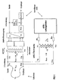
- FIG. 1 a connection scenario currently used in existing subscriber access networks is shown by which a subscriber is provided with both a narrowband subscriber line (ISDN transmission) and a broadband subscriber line (xDSL transmission).
- ISDN transmission narrowband subscriber line
- xDSL transmission broadband subscriber line
- the same frequency spectrum is used in both transmission directions.
- a method for directional separation is required for the transmission of the signals transmitted in both transmission directions via a common transmission channel (here the copper double wire). a method for directional separation is required. Frequently, the echo compensation method is used.
- the directional separation is carried out in a first step by a hybrid circuit - hereinafter also referred to as hybrid - which is arranged in each case at both ends of the transmission line.
- hybrid circuit By the hybrid circuit, the transition between two-wire and four-wire is realized simultaneously.
- the echo cancellation method has the disadvantage that due to the incomplete line simulation in the hybrid circuit and additional reflections on the transmission part of the transmission signal passes as an echo in the own receiver and thus superimposed on the incoming received signal as interference signal.
- this echo becomes adaptive, i. self-adjusting to the line, simulated and subtracted from the signal of the receive direction (consisting of received signal and echo), so that ultimately only the desired received signal reaches the receiver.
- the echo canceller is designed as a transversal filter (low-pass filter) whose coefficients are adaptively adjusted by a controller.
- the upstream signal - In the case of longer subscriber lines, the signal emitted by a subscriber in the direction of the switching center or switching center - referred to below as the upstream signal - is strongly attenuated at the receiving location (switching center) and greatly distorted due to the frequency-dependent group delay.
- the signal sent out in the direction of the subscriber at high power - referred to below as the downstream signal - superimposes itself on the upstream signal.
- the task of the hybrid circuit and of the hybrid and of the echo canceller is to almost completely subtract the downlink signal reflected at the switchboard-side hybrid circuit, which is superimposed in the upstream direction on the payload signal received in the upstream direction. This means that even the slightest change in the impedance of the 2-wire line will lead to a change in the fork transition loss (in terms of phase and amplitude) and the echo canceller together with the equalizer will have to be readjusted.
- the connection scenario illustrated here applies to the transformer Tr1 having the impedance of the subscriber line Z Ltg is completed.
- the impedance Z xDSL of the xDSL transmission or the xDSL line driver side is present.
- the transmission path of the xDSL transmission has only a small stopband attenuation in the frequency range of the ISDN transmission (up to approximately 140 kHz), so that changes in impedance on the xDSL line driver side also affect the input impedance Z xDSL . Even a slight change in the input impedance Z xDSL therefore leads to disruptions and interruptions of the ISDN transmission.
- these impedance changes currently occur through the activation or deactivation of xDSL line drivers. These are in the idle state usually high impedance, alternatively, they may also have a low value.
- the invention is thus based on the object of avoiding disruptive interruptions of the ISDN transmission on subscriber lines caused by the activation or deactivation of the xDSL transmission, in particular the xDSL line driver.
- the object is achieved on the basis of a communication arrangement and a transmission device according to the features of the preamble of claims 1 and 8 by the respective characterizing features. Furthermore, the object is achieved by a connectable to the transmission unit circuit arrangement according to the features of claim 13.
- At least one transmission unit each having an active or passive operating state for transmitting and / or receiving information having an input impedance dependent on the current operating state is connected to at least one transmission line.
- detection means which detect the current operating state of the transmission unit are provided, to which impedance means are assigned, by means of which, depending on the determined operating state, at least a switchable electrical component is switched in such a way that the input impedance of the at least one transmission unit is kept at an approximately constant value.
- the essential advantage of the communication arrangement according to the invention is that impedance jumps in the activation or deactivation of the transmission unit connected to the transmission line are prevented. By avoiding impedance jumps, the disruption of an already ongoing transmission of information over the same transmission line - e.g. an ISDN transmission - avoided. By avoiding impedance jumps, the fork transition loss (in terms of phase and amplitude) is kept at an approximately constant value, so that with respect to the ISDN transmission of the echo canceller and equalizer no longer needs to be readjusted.
- FIG. 2 already shows this in general FIG. 1 explained connection scenario, which represents the exchange end of both narrowband transmission (ISDN transmission) and broadband transmission (xDSL transmission).
- the in FIG. 1 generally illustrated line driver designed as an xDSL line driver LD with impedance synthesis.
- the xDSL line driver LD comprises 2 operational amplifiers OP1,2, which each have an output AO.
- the outputs AO of the two operational amplifiers OP1, 2 can be connected to one another via a switch S and an impedance Z Syn .
- the switch S is connected to an evaluation logic by means of which the active or passive state of the xDSL line driver LD can be determined.
- the evaluation logic can be configured as a detection unit EE assigned to the xDSL line driver LD for evaluating wake-up signals transmitted via the transmission line UL in accordance with the ITU-T G.992.2 standard.
- the current active or passive state can be determined by the detection unit EE and the switch S can be opened or closed depending on the determined state.
- the outputs AO of the two operational amplifiers OP1,2 are each fed back via a resistor R3 T , R3 R to a corresponding input EO of the respective operational amplifier OP1,2.
- the input EO of the first operational amplifier OP1 is connected via a resistor R2 T and a resistor R1 R to the output AO of the second operational amplifier OP2.
- the input EO of the second operational amplifier OP2 is connected via a resistor R2 R and a resistor R1 T to the output AO of the first operational amplifier OP1.
- the outputs of the two operational amplifiers OP1,2 are each connected via the resistor R1 T , R1 R to a transformer Tr2.
- the inputs EO of the two operational amplifiers OP1,2 are connected to one another via resistors R4 T , R4 R and via an alternating voltage source U 0 (which in this embodiment represents the xDSL data signal to be transmitted in the direction of the subscriber).
- the xDSL line driver LD is connected to the subscriber line UL.
- the xDSL line driver LD is activated only when actually connected to the subscriber line UL to be transmitted information from the exchange VST or when wake-up signals are detected by the detection unit.
- the transmission line UL associated inductors L1 T , L1 R represent a low-pass filter, are attenuated by which frequency components of the xDSL transmission, which are above the frequency spectrum of the ISDN transmission.
- the capacitors C1, C2 are used for DC separation.
- R ⁇ 1 T R ⁇ 1 R .
- R ⁇ 4 T R ⁇ 4 R R ⁇ 2 .
- the resistors R2, R3 and R4 can generally be neglected, since they are approximately 2 orders of magnitude above the value of R1.
- the switchable impedance Z syn according to the invention can alternatively-optionally together with the switch S-be configured as an external additional circuit assigned to the xDSL line driver-not shown.
- the additional circuit may also include the detection unit EE.
Landscapes
- Engineering & Computer Science (AREA)
- Computer Networks & Wireless Communication (AREA)
- Signal Processing (AREA)
- Cable Transmission Systems, Equalization Of Radio And Reduction Of Echo (AREA)
- Dc Digital Transmission (AREA)
- Interface Circuits In Exchanges (AREA)
Claims (14)
- Dispositif de communication pour la transmission d'informations, comprenant au moins une ligne de transmission (UL) ainsi qu'au moins une unité de transmission (LD), raccordée à la ligne de transmission (UL) et présentant respectivement un état de fonctionnement actif ou passif, pour émettre et/ou recevoir des informations avec une impédance d'entrée (ZxDSL) qui dépend de l'état de fonctionnement actuel,
caractérisé en ce que- sont prévus des moyens de détection (EE) qui détectent l'état de fonctionnement actuel de l'unité de transmission (LD),- sont prévus des moyens d'impédance (S1, ZSyn) associés au moyens de détection (EE) et par lesquels au moins un composant électrique commutable (ZSyn) est commuté de manière telle, en fonction de l'état de fonctionnement détecté, que l'impédance d'entrée (ZxDSL) de l'au moins une unité de transmission (LD) est maintenue à une valeur approximativement constante. - Dispositif de communication selon la revendication 1,
caractérisé en ce que- l'unité de transmission (LD) comprend au moins deux amplificateurs d'opération (OP1, OP2) qui émettent sur l'au moins une ligne de transmission (UL) les informations à transmettre,- l'au moins un composant électrique (ZSyn) étant commuté entre des sorties (AO) des deux amplificateurs d'opération (OP1, OP2) par l'intermédiaire d'un commutateur (S1) commandé par les moyens de détection (EE), les moyens d'impédance (S, ZSyn) et les moyens de détection (EE) étant réalisés de manière telle que le commutateur (S1) est ouvert à l'état de fonctionnement actif et est fermé à l'état de fonctionnement passif. - Dispositif de communication selon la revendication 1 ou 2, caractérisé en ce que l'au moins un composant électrique comprend au moins une résistance électrique (ZSyn).
- Dispositif de communication selon l'une des revendications précédentes, caractérisé en ce que l'unité de transmission (LD) est réalisée pour émettre et/ou pour recevoir des informations selon un procédé de transmission xDSL.
- Dispositif de communication selon l'une des revendications précédentes, caractérisé en ce qu'est raccordée, à l'au moins une ligne de transmission (UL), au moins une autre unité de transmission pour émettre et/ou pour recevoir des informations réalisées conformément au procédé de transmission RNIS.
- Dispositif de communication selon l'une des revendications précédentes, caractérisé en ce que- les moyens de détection (EE) sont réalisés de manière telle que des signaux d'activation transmis sur l'au moins une ligne de transmission (UL) sont détectés,- les moyens de détection (EE) sont réalisés de manière telle que, à la détection d'un signal d'activation, l'état de fonctionnement actif de l'unité de transmission (LD) est constaté.
- Dispositif de communication selon la revendication 6, caractérisé en ce que les signaux d'activation se présentent sous la forme de signaux wake-up conformément au standard G.922 de l'UIT-T.
- Unité de transmission (LD) pour émettre et/ou recevoir des informations via au moins une ligne de transmission (UL) raccordable, l'unité de transmission (LD) présentant un état de fonctionnement actif ou passif ainsi qu'une impédance d'entrée (ZxDSL) qui dépend de l'état de fonctionnement actuel,
caractérisée en ce que- sont prévus des moyens de détection (EE) qui détectent l'état de fonctionnement actuel de l'unité de transmission (LD),- sont prévus des moyens d'impédance (S1, ZSyn) associés au moyens de détection (EE) et par lesquels au moins un composant électrique commutable (ZSyn) est commuté de manière telle, en fonction de l'état de fonctionnement actuel détecté, que l'impédance d'entrée (ZxDSL) de l'unité de transmission (LD) est maintenue à une valeur approximativement constante. - Unité de transmission selon la revendication 8, caractérisée en ce que- au moins deux amplificateurs d'opération (OP1, OP2) qui émettent sur l'au moins une ligne de transmission (UL) les informations à transmettre sont montés,- l'au moins un composant électrique (ZSyn) est commuté entre des sorties (AO) des deux amplificateurs d'opération (OP1, 2) par l'intermédiaire d'un commutateur (S1) commandé par les moyens de détection (EE), les moyens d'impédance (S, ZSyn) et les moyens de détection (EE) étant réalisés de manière telle que le commutateur (S1) est ouvert à l'état de fonctionnement actif et est fermé à l'état de fonctionnement passif.
- Unité de transmission selon la revendication 8 ou 9, caractérisée en ce que l'au moins un composant électrique comprend au moins une résistance électrique (ZSyn).
- Unité de transmission selon l'une des revendications 8 à 10, caractérisée en ce que l'unité de transmission (LD) est réalisée pour émettre et/ou pour recevoir des informations selon un procédé de transmission xDSL.
- Unité de transmission selon l'une des revendications 8 à 11, caractérisée en ce que les moyens de détection et les moyens d'impédance se présentent sous la forme d'un ensemble de circuit raccordable de manière externe à l'unité de transmission (LD).
- Ensemble de circuit destiné à être raccordé de manière externe à une unité de transmission selon l'une des revendications 8 à 12, caractérisée en ce que sont prévus des moyens d'impédance (S1, ZSyn) pouvant être reliés aux moyens de détection (EE) situés dans l'unité de transmission, lesquels moyens d'impédance se présentent de manière telle que l'impédance d'entrée (ZxDSL) de l'unité de transmission (LD) est, en fonction de l'état de fonctionnement actuel déterminé, maintenue à une valeur approximativement constante à l'aide d'au moins un composant électrique commutable (ZSyn).
- Ensemble de circuit selon la revendication 13, caractérisé en ce que les moyens de détection (EE) sont inclus dans le circuit.
Applications Claiming Priority (3)
| Application Number | Priority Date | Filing Date | Title |
|---|---|---|---|
| DE10240140 | 2002-08-30 | ||
| DE10240140A DE10240140A1 (de) | 2002-08-30 | 2002-08-30 | Kommunikationsanordnung und Übertragungseinheit zur Informationsübermittlung über zumindest eine Übertragungsleitung sowie eine an die Übertragungseinheit anschließbare Schaltungsanordnung |
| PCT/DE2003/002673 WO2004023776A2 (fr) | 2002-08-30 | 2003-08-08 | Systeme de communication et unite de transmission pour la transmission d'informations par l'intermediaire d'au moins une ligne de transmission et ensemble circuit pouvant etre relie a cette unite de transmission |
Publications (2)
| Publication Number | Publication Date |
|---|---|
| EP1532802A2 EP1532802A2 (fr) | 2005-05-25 |
| EP1532802B1 true EP1532802B1 (fr) | 2009-10-14 |
Family
ID=31895616
Family Applications (1)
| Application Number | Title | Priority Date | Filing Date |
|---|---|---|---|
| EP03793592A Expired - Lifetime EP1532802B1 (fr) | 2002-08-30 | 2003-08-08 | Systeme de communication et unite de transmission pour la transmission d'informations par l'intermediaire d'au moins une ligne de transmission et ensemble circuit pouvant etre relie a cette unite de transmission |
Country Status (6)
| Country | Link |
|---|---|
| US (1) | US20060029213A1 (fr) |
| EP (1) | EP1532802B1 (fr) |
| CN (1) | CN1679315B (fr) |
| DE (2) | DE10240140A1 (fr) |
| ES (1) | ES2333653T3 (fr) |
| WO (1) | WO2004023776A2 (fr) |
Families Citing this family (1)
| Publication number | Priority date | Publication date | Assignee | Title |
|---|---|---|---|---|
| DE102015219666B4 (de) * | 2015-10-12 | 2023-02-16 | Robert Bosch Gmbh | Kommunikationssystem für ein Batteriemanagementsystem für eine Batterie und Verfahren zum Betreiben wenigstens eines vorbestimmten Koppelnetzwerks eines solchen Kommunikationssystems |
Family Cites Families (21)
| Publication number | Priority date | Publication date | Assignee | Title |
|---|---|---|---|---|
| US4267532A (en) * | 1979-10-11 | 1981-05-12 | W. L. Keefauver, Bell Laboratories | Adjustable microstrip and stripline tuners |
| US4402082A (en) * | 1980-10-31 | 1983-08-30 | Foster Wheeler Energy Corporation | Automatic line termination in distributed industrial process control system |
| US4316160A (en) * | 1980-07-28 | 1982-02-16 | Motorola Inc. | Impedance transforming hybrid ring |
| US5856758A (en) * | 1996-11-20 | 1999-01-05 | Adtran, Inc. | Low distortion driver employing positive feedback for reducing power loss in output impedance that effectively matches the impedance of driven line |
| US6269154B1 (en) * | 1998-02-04 | 2001-07-31 | Texas Instruments Incorporated | Splitterless modem with integrated off-hook detector |
| US6208732B1 (en) * | 1998-02-12 | 2001-03-27 | Globespan Semiconductor, Inc. | Switched hybrid circuit for use with digital subscriber lines |
| US6724890B1 (en) * | 1998-11-24 | 2004-04-20 | Premisenet Incorporated | Adaptive transmission line impedance matching device and method |
| US6728370B1 (en) * | 1999-03-15 | 2004-04-27 | Legerity, Inc. | Method and apparatus for impedance matching |
| US6211719B1 (en) * | 1999-04-19 | 2001-04-03 | Globespan Semiconductor Inc. | Power control circuit for a line driver |
| US6813343B1 (en) * | 1999-05-12 | 2004-11-02 | Orckitt Communications Ltd. | Method and apparatus for filtering asymmetric digital subscriber line (ADSL) signals |
| WO2000079693A1 (fr) * | 1999-06-18 | 2000-12-28 | 2Wire, Inc. | Configuration hybride active a adaptation d'impedance dynamique par rapport a differentes conditions de boucle, et procede correspondant |
| US6430266B2 (en) * | 1999-07-28 | 2002-08-06 | Legerity, Inc. | Apparatus and method for examining and standardizing line connections |
| US6351185B1 (en) * | 1999-08-16 | 2002-02-26 | Globespan, Inc. | Increased output swing line drivers for operation at supply voltages that exceed the breakdown voltage of the integrated circuit technology |
| AU5401499A (en) * | 1999-10-14 | 2001-04-26 | Alcatel | ADSL filter |
| US7106854B2 (en) * | 2000-01-25 | 2006-09-12 | Sbc Knowledge Ventures, L.P. | XDSL system having selectable hybrid circuitry |
| US7177349B2 (en) * | 2000-01-28 | 2007-02-13 | Sasken Communication Technologies, Ltd. | High impedance state for digital subscriber line transceivers on copper twisted pairs |
| EP1148683A3 (fr) * | 2000-03-01 | 2004-05-06 | Virata Corporation | Circuit hybride adaptatif pour la communication multiporteuse |
| US6738418B1 (en) * | 2000-04-03 | 2004-05-18 | Virata Corporation | Method and apparatus for adaptive data allocation in a multi-carrier communication system |
| EP1248444A1 (fr) * | 2001-02-12 | 2002-10-09 | Harris Corporation | Appareil téléphonique de test analogue possedant un filtre passe-bas et des resistances couplées avec les lignes de connection pour prévenir l'alteration des signaux de communication numériques |
| US7483528B2 (en) * | 2001-02-06 | 2009-01-27 | 2Wire, Inc. | Loop extender with selectable line termination and equalization |
| US6577154B2 (en) * | 2001-05-03 | 2003-06-10 | International Business Machines Corporation | Constant impedance driver for high speed interface |
-
2002
- 2002-08-30 DE DE10240140A patent/DE10240140A1/de not_active Withdrawn
-
2003
- 2003-08-08 US US10/525,156 patent/US20060029213A1/en not_active Abandoned
- 2003-08-08 EP EP03793592A patent/EP1532802B1/fr not_active Expired - Lifetime
- 2003-08-08 WO PCT/DE2003/002673 patent/WO2004023776A2/fr not_active Ceased
- 2003-08-08 DE DE50312028T patent/DE50312028D1/de not_active Expired - Lifetime
- 2003-08-08 ES ES03793592T patent/ES2333653T3/es not_active Expired - Lifetime
- 2003-08-08 CN CN03820511.4A patent/CN1679315B/zh not_active Expired - Lifetime
Also Published As
| Publication number | Publication date |
|---|---|
| ES2333653T3 (es) | 2010-02-25 |
| US20060029213A1 (en) | 2006-02-09 |
| WO2004023776A3 (fr) | 2004-06-24 |
| CN1679315B (zh) | 2010-10-13 |
| EP1532802A2 (fr) | 2005-05-25 |
| CN1679315A (zh) | 2005-10-05 |
| DE50312028D1 (de) | 2009-11-26 |
| DE10240140A1 (de) | 2004-03-25 |
| WO2004023776A2 (fr) | 2004-03-18 |
Similar Documents
| Publication | Publication Date | Title |
|---|---|---|
| DE3001362C3 (de) | Schaltungsanordnung zum Regeln des Speisestroms für zentralgespeiste Fernsprechapparate | |
| EP3375149A1 (fr) | Dispositif et procédé de suppression sélective d'oscillations de bus lors de la réception de données par le biais d'un système de bus | |
| EP1293049B1 (fr) | Ensemble circuit pour la suppression analogique d'echos | |
| DE112015000240T5 (de) | Schnittstellenschaltung mit Datenbusschnittstelle | |
| DE2635021A1 (de) | Schaltungsanordnung zur aenderung der impedanzeigenschaften einer uebertragungsleitung | |
| DE60217101T2 (de) | Leitungsschnittstellenschaltung mit impedanzanpassung, die eine rückkopplungspfad angeschlossenen ist | |
| EP3216173A1 (fr) | Système et procédé pour optimiser la transmission de données numériques dans des réseaux de communication bifilaires | |
| DE102009038272A1 (de) | Verfahren und Vorrichtung zur Datenübertragung | |
| DE10053763C2 (de) | Feldbussystem zum Steuern von sicherheitskritischen Prozessen sowie Busanschaltmodul zur Verwendung in einem solchen Feldbussystem | |
| EP1532802B1 (fr) | Systeme de communication et unite de transmission pour la transmission d'informations par l'intermediaire d'au moins une ligne de transmission et ensemble circuit pouvant etre relie a cette unite de transmission | |
| EP1206846A1 (fr) | Dispositif de couplage pour systeme de transmission de donnees pour reseaux basse tension | |
| EP0774185B1 (fr) | Station raccordee a un bus | |
| EP1906545A2 (fr) | Procédé de transmission d'un signal d'émission numérique, émetteur de communication de données, récepteur de communication de données et système de communication de données | |
| DE10147924A1 (de) | Verfahren und Einrichtung zur übertragerlosen Spannungsversorgung | |
| EP1665637B1 (fr) | Procede et dispositif de communication destines au controle de lignes de connexion d'abonnes | |
| DE68905782T2 (de) | Verfahren und anordnung zur adaptiven digitalen loeschung des im fernsprechverbindungen mit zeitvarianten eigenschaften erzeugten echos. | |
| DE102018220073A1 (de) | Leitungsabschluss für einen Bus eines Bussystems und Verfahren zum Unterdrücken von Reflexionen aufgrund von Gleichtaktstörungen in einem Bussystem | |
| DE102004014313B4 (de) | Netzwerk-Vorrichtung, insbesondere Aktuator-Sensor-Interface-Netzwerk | |
| DE69734888T2 (de) | Schaltungskonfiguration zur Anpassung eines Mehrgeschwindigkeitsmodems an eine Leitung und entsprechende Anpassungsmethode | |
| DE60125501T2 (de) | Einrichtung zum Anschluss einer Teilnehmerleitung an eine Verbindung mit hoher Frequenz und eine Verbindung mit niedriger Frequenz | |
| DE69526872T2 (de) | Telefontrennungsvorrichtung | |
| DE102006034835B4 (de) | Vorrichtung und Verfahren zum Aufbereiten eines Signals | |
| WO2012139641A1 (fr) | Système de transmission et procédé de fonctionnement correspondant | |
| DE69532933T2 (de) | Telefontrennungsvorrichtung | |
| EP0927471A1 (fr) | Circuit hybride |
Legal Events
| Date | Code | Title | Description |
|---|---|---|---|
| PUAI | Public reference made under article 153(3) epc to a published international application that has entered the european phase |
Free format text: ORIGINAL CODE: 0009012 |
|
| 17P | Request for examination filed |
Effective date: 20050201 |
|
| AK | Designated contracting states |
Kind code of ref document: A2 Designated state(s): AT BE BG CH CY CZ DE DK EE ES FI FR GB GR HU IE IT LI LU MC NL PT RO SE SI SK TR |
|
| RBV | Designated contracting states (corrected) |
Designated state(s): DE ES FR GB IT |
|
| 17Q | First examination report despatched |
Effective date: 20070622 |
|
| RAP1 | Party data changed (applicant data changed or rights of an application transferred) |
Owner name: NOKIA SIEMENS NETWORKS GMBH & CO. KG |
|
| RAP3 | Party data changed (applicant data changed or rights of an application transferred) |
Owner name: NOKIA SIEMENS NETWORKS S.P.A. |
|
| RAP3 | Party data changed (applicant data changed or rights of an application transferred) |
Owner name: NOKIA SIEMENS NETWORKS GMBH & CO. KG |
|
| GRAP | Despatch of communication of intention to grant a patent |
Free format text: ORIGINAL CODE: EPIDOSNIGR1 |
|
| GRAS | Grant fee paid |
Free format text: ORIGINAL CODE: EPIDOSNIGR3 |
|
| GRAA | (expected) grant |
Free format text: ORIGINAL CODE: 0009210 |
|
| AK | Designated contracting states |
Kind code of ref document: B1 Designated state(s): DE ES FR GB IT |
|
| REG | Reference to a national code |
Ref country code: GB Ref legal event code: FG4D Free format text: NOT ENGLISH |
|
| REF | Corresponds to: |
Ref document number: 50312028 Country of ref document: DE Date of ref document: 20091126 Kind code of ref document: P |
|
| REG | Reference to a national code |
Ref country code: ES Ref legal event code: FG2A Ref document number: 2333653 Country of ref document: ES Kind code of ref document: T3 |
|
| PLBE | No opposition filed within time limit |
Free format text: ORIGINAL CODE: 0009261 |
|
| STAA | Information on the status of an ep patent application or granted ep patent |
Free format text: STATUS: NO OPPOSITION FILED WITHIN TIME LIMIT |
|
| 26N | No opposition filed |
Effective date: 20100715 |
|
| REG | Reference to a national code |
Ref country code: DE Ref legal event code: R081 Ref document number: 50312028 Country of ref document: DE Owner name: NOKIA SOLUTIONS AND NETWORKS GMBH & CO. KG, DE Free format text: FORMER OWNER: NOKIA SIEMENS NETWORKS GMBH & CO. KG, 81541 MUENCHEN, DE Effective date: 20140731 Ref country code: DE Ref legal event code: R081 Ref document number: 50312028 Country of ref document: DE Owner name: BEIJING XIAOMI MOBILE SOFTWARE CO., LTD., CN Free format text: FORMER OWNER: NOKIA SIEMENS NETWORKS GMBH & CO. KG, 81541 MUENCHEN, DE Effective date: 20140731 |
|
| REG | Reference to a national code |
Ref country code: ES Ref legal event code: PC2A Owner name: NOKIA SOLUTIONS AND NETWORKS GMBH & CO.KG Effective date: 20141121 |
|
| REG | Reference to a national code |
Ref country code: FR Ref legal event code: CD Owner name: NOKIA SOLUTIONS AND NETWORKS GMBH & CO.KG, DE Effective date: 20150211 |
|
| REG | Reference to a national code |
Ref country code: FR Ref legal event code: PLFP Year of fee payment: 13 |
|
| REG | Reference to a national code |
Ref country code: FR Ref legal event code: PLFP Year of fee payment: 14 |
|
| PGFP | Annual fee paid to national office [announced via postgrant information from national office to epo] |
Ref country code: IT Payment date: 20160825 Year of fee payment: 14 Ref country code: GB Payment date: 20160819 Year of fee payment: 14 |
|
| PGFP | Annual fee paid to national office [announced via postgrant information from national office to epo] |
Ref country code: FR Payment date: 20160822 Year of fee payment: 14 |
|
| GBPC | Gb: european patent ceased through non-payment of renewal fee |
Effective date: 20170808 |
|
| REG | Reference to a national code |
Ref country code: FR Ref legal event code: ST Effective date: 20180430 |
|
| REG | Reference to a national code |
Ref country code: ES Ref legal event code: PC2A Effective date: 20180530 Ref country code: ES Ref legal event code: PC2A Owner name: BEIJING XIAOMI MOBILE SOFTWARE CO., LTD Effective date: 20180530 |
|
| PG25 | Lapsed in a contracting state [announced via postgrant information from national office to epo] |
Ref country code: GB Free format text: LAPSE BECAUSE OF NON-PAYMENT OF DUE FEES Effective date: 20170808 |
|
| REG | Reference to a national code |
Ref country code: DE Ref legal event code: R081 Ref document number: 50312028 Country of ref document: DE Owner name: BEIJING XIAOMI MOBILE SOFTWARE CO., LTD., CN Free format text: FORMER OWNER: NOKIA SOLUTIONS AND NETWORKS GMBH & CO. KG, 81541 MUENCHEN, DE |
|
| PG25 | Lapsed in a contracting state [announced via postgrant information from national office to epo] |
Ref country code: IT Free format text: LAPSE BECAUSE OF NON-PAYMENT OF DUE FEES Effective date: 20170808 Ref country code: FR Free format text: LAPSE BECAUSE OF NON-PAYMENT OF DUE FEES Effective date: 20170831 |
|
| PGFP | Annual fee paid to national office [announced via postgrant information from national office to epo] |
Ref country code: DE Payment date: 20220620 Year of fee payment: 20 |
|
| PGFP | Annual fee paid to national office [announced via postgrant information from national office to epo] |
Ref country code: ES Payment date: 20221024 Year of fee payment: 20 |
|
| P01 | Opt-out of the competence of the unified patent court (upc) registered |
Effective date: 20230531 |
|
| REG | Reference to a national code |
Ref country code: DE Ref legal event code: R071 Ref document number: 50312028 Country of ref document: DE |
|
| REG | Reference to a national code |
Ref country code: ES Ref legal event code: FD2A Effective date: 20230825 |
|
| PG25 | Lapsed in a contracting state [announced via postgrant information from national office to epo] |
Ref country code: ES Free format text: LAPSE BECAUSE OF EXPIRATION OF PROTECTION Effective date: 20230809 |