EP1532607B1 - Verfahren und vorrichtung zur bearbeitung von videobildern zurverbesserten kompensation des dynamischen falschfarbeneffekts - Google Patents
Verfahren und vorrichtung zur bearbeitung von videobildern zurverbesserten kompensation des dynamischen falschfarbeneffekts Download PDFInfo
- Publication number
- EP1532607B1 EP1532607B1 EP03761583.8A EP03761583A EP1532607B1 EP 1532607 B1 EP1532607 B1 EP 1532607B1 EP 03761583 A EP03761583 A EP 03761583A EP 1532607 B1 EP1532607 B1 EP 1532607B1
- Authority
- EP
- European Patent Office
- Prior art keywords
- noise
- sub
- motion
- field
- counter
- Prior art date
- Legal status (The legal status is an assumption and is not a legal conclusion. Google has not performed a legal analysis and makes no representation as to the accuracy of the status listed.)
- Expired - Lifetime
Links
Images






Classifications
-
- G—PHYSICS
- G06—COMPUTING OR CALCULATING; COUNTING
- G06T—IMAGE DATA PROCESSING OR GENERATION, IN GENERAL
- G06T5/00—Image enhancement or restoration
- G06T5/73—Deblurring; Sharpening
-
- G—PHYSICS
- G06—COMPUTING OR CALCULATING; COUNTING
- G06T—IMAGE DATA PROCESSING OR GENERATION, IN GENERAL
- G06T5/00—Image enhancement or restoration
- G06T5/20—Image enhancement or restoration using local operators
-
- G—PHYSICS
- G06—COMPUTING OR CALCULATING; COUNTING
- G06T—IMAGE DATA PROCESSING OR GENERATION, IN GENERAL
- G06T7/00—Image analysis
- G06T7/20—Analysis of motion
- G06T7/223—Analysis of motion using block-matching
- G06T7/231—Analysis of motion using block-matching using full search
-
- G—PHYSICS
- G09—EDUCATION; CRYPTOGRAPHY; DISPLAY; ADVERTISING; SEALS
- G09G—ARRANGEMENTS OR CIRCUITS FOR CONTROL OF INDICATING DEVICES USING STATIC MEANS TO PRESENT VARIABLE INFORMATION
- G09G3/00—Control arrangements or circuits, of interest only in connection with visual indicators other than cathode-ray tubes
- G09G3/20—Control arrangements or circuits, of interest only in connection with visual indicators other than cathode-ray tubes for presentation of an assembly of a number of characters, e.g. a page, by composing the assembly by combination of individual elements arranged in a matrix no fixed position being assigned to or needed to be assigned to the individual characters or partial characters
- G09G3/2007—Display of intermediate tones
- G09G3/2018—Display of intermediate tones by time modulation using two or more time intervals
- G09G3/2022—Display of intermediate tones by time modulation using two or more time intervals using sub-frames
- G09G3/2029—Display of intermediate tones by time modulation using two or more time intervals using sub-frames the sub-frames having non-binary weights
-
- G—PHYSICS
- G09—EDUCATION; CRYPTOGRAPHY; DISPLAY; ADVERTISING; SEALS
- G09G—ARRANGEMENTS OR CIRCUITS FOR CONTROL OF INDICATING DEVICES USING STATIC MEANS TO PRESENT VARIABLE INFORMATION
- G09G3/00—Control arrangements or circuits, of interest only in connection with visual indicators other than cathode-ray tubes
- G09G3/20—Control arrangements or circuits, of interest only in connection with visual indicators other than cathode-ray tubes for presentation of an assembly of a number of characters, e.g. a page, by composing the assembly by combination of individual elements arranged in a matrix no fixed position being assigned to or needed to be assigned to the individual characters or partial characters
- G09G3/2007—Display of intermediate tones
- G09G3/2044—Display of intermediate tones using dithering
- G09G3/2051—Display of intermediate tones using dithering with use of a spatial dither pattern
-
- H—ELECTRICITY
- H04—ELECTRIC COMMUNICATION TECHNIQUE
- H04N—PICTORIAL COMMUNICATION, e.g. TELEVISION
- H04N5/00—Details of television systems
- H04N5/14—Picture signal circuitry for video frequency region
- H04N5/21—Circuitry for suppressing or minimising disturbance, e.g. moiré or halo
- H04N5/213—Circuitry for suppressing or minimising impulsive noise
-
- G—PHYSICS
- G06—COMPUTING OR CALCULATING; COUNTING
- G06T—IMAGE DATA PROCESSING OR GENERATION, IN GENERAL
- G06T2207/00—Indexing scheme for image analysis or image enhancement
- G06T2207/10—Image acquisition modality
- G06T2207/10016—Video; Image sequence
-
- G—PHYSICS
- G09—EDUCATION; CRYPTOGRAPHY; DISPLAY; ADVERTISING; SEALS
- G09G—ARRANGEMENTS OR CIRCUITS FOR CONTROL OF INDICATING DEVICES USING STATIC MEANS TO PRESENT VARIABLE INFORMATION
- G09G2320/00—Control of display operating conditions
- G09G2320/02—Improving the quality of display appearance
- G09G2320/0261—Improving the quality of display appearance in the context of movement of objects on the screen or movement of the observer relative to the screen
-
- G—PHYSICS
- G09—EDUCATION; CRYPTOGRAPHY; DISPLAY; ADVERTISING; SEALS
- G09G—ARRANGEMENTS OR CIRCUITS FOR CONTROL OF INDICATING DEVICES USING STATIC MEANS TO PRESENT VARIABLE INFORMATION
- G09G2320/00—Control of display operating conditions
- G09G2320/02—Improving the quality of display appearance
- G09G2320/0266—Reduction of sub-frame artefacts
-
- G—PHYSICS
- G09—EDUCATION; CRYPTOGRAPHY; DISPLAY; ADVERTISING; SEALS
- G09G—ARRANGEMENTS OR CIRCUITS FOR CONTROL OF INDICATING DEVICES USING STATIC MEANS TO PRESENT VARIABLE INFORMATION
- G09G3/00—Control arrangements or circuits, of interest only in connection with visual indicators other than cathode-ray tubes
- G09G3/20—Control arrangements or circuits, of interest only in connection with visual indicators other than cathode-ray tubes for presentation of an assembly of a number of characters, e.g. a page, by composing the assembly by combination of individual elements arranged in a matrix no fixed position being assigned to or needed to be assigned to the individual characters or partial characters
- G09G3/22—Control arrangements or circuits, of interest only in connection with visual indicators other than cathode-ray tubes for presentation of an assembly of a number of characters, e.g. a page, by composing the assembly by combination of individual elements arranged in a matrix no fixed position being assigned to or needed to be assigned to the individual characters or partial characters using controlled light sources
- G09G3/28—Control arrangements or circuits, of interest only in connection with visual indicators other than cathode-ray tubes for presentation of an assembly of a number of characters, e.g. a page, by composing the assembly by combination of individual elements arranged in a matrix no fixed position being assigned to or needed to be assigned to the individual characters or partial characters using controlled light sources using luminous gas-discharge panels, e.g. plasma panels
Definitions
- the present invention relates to a method for processing video pictures, especially a method improving dynamic false contour effect compensation in matrix display screens based on the principle of duty cycle modulation (PWM for Pulse Width Modulation) of light emission.
- PWM Pulse Width Modulation
- the invention also relates to an apparatus for carrying out the method.
- the invention will be described in relation with plasma display panels (PDPs) but may be applicable to all kinds of displays based on the principle of duty cycle modulation such as DMD (Digital Micro-mirror Devices) or similar.
- plasma display panels are known for many years, plasma displays are encountering a growing interest from TV manufacturers. Indeed, this technology now makes it possible to achieve flat color panels of large size and with limited depths without any viewing angle constraints.
- the size of the displays may be much larger than the classical CRT picture tubes would have ever been allowed.
- the invention deals with a specific new artefact, which is called "dynamic false contour effect" since it corresponds to disturbances of gray levels and colors in the form of an apparition of colored edges in the picture when an observation point on the matrix screen moves.
- This kind of artefact is enhanced when the image has a smooth gradation like when the skin of a person is being displayed (e. g. displaying of a face or an arm, etc.).
- the same problem occurs on static images when observers are shaking their heads and that leads to the conclusion that such a failure depends on the human visual perception and happens on the retina of the eye.
- the object of the invention is to propose a new method optimising the choice of the coding depending on picture activity in terms of movement and noise.
- the present invention relates to a method for processing video pictures for display on a display device having a plurality of luminous elements corresponding to the pixels of a picture wherein the time of a video frame or field is divided into a plurality of N sub-fields (SF) during which the luminous elements can be activated for light emission in small pulses corresponding to a sub-field code word of n bits used for coding the p possible video levels lighting a pixel, comprising the steps of:
- the first sub-field encoding method is a standard encoding method wherein the n bit video level is decomposed in n or more lighting sub-periods or sub-fields.
- the second sub-field encoding method is a method wherein among the set of p possible video levels for lighting a pixel, a sub-set of m video levels with n ⁇ m ⁇ p is selected, which is used for light generation, wherein the m values are selected according to the rule that the temporal centre of gravity for the light generation of the corresponding sub-field code words grow continuously with the video level apart in the low video level range up to a first predefined limit and/or in the high video level range from a second predefined limit on.
- the set of possible sub-field code words is reduced by taking only those sub-field code words for each video level, which have the minimum binary value for the case that in a sub-field code word the weight of each bit is ordered according to size.
- the selection of video levels from the further reduced set of sub-field code words is performed by taking only one video level on each group of sub-field code words having the same radical on the MSB side, namely the video level belonging to the next higher group of sub-field code words and having the smallest centre of gravity superior to the centre of gravity of the previous selected video level, wherein in case that the next higher group of sub-field code words does not provide a sub-field code word having a centre of gravity inferior to the previous one, then the second next higher sub-field code word group will be chosen for selecting the next video level and so on.
- the method comprises an additional step of :
- the decision to switch between the first sub-field encoding method and the second sub-field encoding method in view of the detection of the motion is done according to the following algorithm :
- the motion detection can be done by using the following method comprising the steps of :
- the histogram of the zone is defined by choosing a number of discrete regions, each one defined by lower and upper video frontiers.
- This algorithm has the advantage to be quite simple. No specific frame memory is required since only histograms are memorized which represent only few bits.
- the noise detection can be done using the following method comparing two consecutive lines A(i), B(i).
- the method comprises the following steps of :
- the noise detection can be done using the following method :
- the estimation of the final noise is done using a histogram representation of the various mean square errors MSE(n').
- MSE mean square errors
- the highest value in the occurrence of the histogram is chosen to quantify the MSE of the whole picture.
- the noise can be detected using the following steps :
- the method comprises the following steps of:
- the present invention relates to a method improving false contour effect compensation in matrix displays screens using a PWM modulation of light emission, for example in plasma display panels.
- a first sub-field encoding method more particularly the standard encoding method is used when no motion is detected and a second sub-field encoding method is used when motion is detected.
- PDP plasma display panel
- gray levels can not be expressed by analog control of the light emission.
- a PDP controls gray levels by a plulse width modulation (PWM) of each cells, i.e. by modulating the number of light pulses per frame period. This time modulation will be integrated by the eye over a period corresponding to the eye time response. The more often a cell is switched on in a given time frame, the higher is its luminance.
- PWM plulse width modulation
- a minimum of 8 sub-fields are used in a sub-field organization for a frame period.
- each video level for each colour component will be represented by a combination of 8 bits with the following weights: 1 / 2 / 4 / 8 / 16 / 32 / 64 / 128
- the frame period will be divided in 8 lighting periods called sub-fields, each one corresponding to a bit in a corresponding sub-field code word.
- the number of light pulses for the bit "2" is double as for the bit "1" and so forth. So, as mentioned above, with these 8 sub-periods it is possible, through sub-field combination, to build the 256 gray levels.
- the light emission pattern according to the sub-field organization introduces new categories of image quality degradation corresponding to disturbances of gray levels and colours.
- These disturbances are defined as so called dynamic false contour effects, due to the fact that they correspond to the appearance of coloured edges in the picture when an observation point on the PDP screen moves.
- the observer has the impression of a strong contour appearing on a homogeneous area like displayed skin.
- the degradation is enhanced when the image has a smooth gradation and also when the light emission period exceeds several milliseconds. So, in dark scenes the effect is not so disturbing as in scenes with average gray level (e.g. luminance values from 32 to 223).
- Fig. 2 shows a darker shaded area corresponding to the luminance level 128 and a lighter shaded area corresponding to the luminance level 127.
- the sub-field organization shown in Fig. 1 is used for building the luminance levels 128 and 127 as it is depicted in the right side of Fig. 2 .
- the three parallel lines in Fig. 2 indicate the direction in which the eye follows the movement.
- the two outer lines show the area borders where a faulty signal will be perceived. Between them the eye will perceive a lack of luminance, which leads to the appearance of a dark edge in the corresponding area, which is illustrated in Fig. 2 at the bottom.
- the effect that the lack of luminance will be perceived in the shown area is due to the fact that the eye will no longer integrate all lighting periods of one pixel when the point from which the eye receives light is in movement. Only part of the light pulses will probably be integrated when the point moves. Therefore, there is a lack of corresponding luminance and a dark edge will occur.
- a curve is shown, which illustrates the behaviour of the eye cells during observing a moving picture depicted in Fig. 2 .
- the eye cells having a good distance from the horizontal transition will integrate enough light from the corresponding pixels. Only the eye cells, which are near the transition, will not be able to integrate a lot of light from the same pictures.
- this effect corresponds to the apparition of artificial white or black edges.
- this effect will occur independently on the different colour components, it will lead to the apparition of coloured edges in homogeneous areas like skin.
- the picture quality of moving images may be improved by using more than 8 sub-fields, for example a sub-field organization based on 10 sub-fields or 12 sub-fields which aim at reducing the weights of the MSBs, which are directly linked to the maximum level of false contour generated.
- standard coding scheme is used when no motion is detected and an other type of coding scheme taking in account the fact that the false contour effect occurs when there is a transition to one level to another, is used when motion is detected.
- Such coding scheme may be, for example, the coding scheme known as gravity centered coding (GCC).
- a PDP emits light pulses in pulse width modulation form and the human eye integrates these light pulses during a frame period in order to perceive the correct brightness impression.
- Fig. 4 it is indicated how the temporal centre of gravity CG1, CG2, CG3 of light emission varies when the video level is incremented one by one in case of a basic sub-field code like the well-known binary code.
- a vertical line indicates the temporal centre of gravity.
- a dark shaded sub-field means that during this sub-field the light generation is activated whereas a light shaded sub-field means that there is no light generation in this sub-field period. From Fig. 4 , it is evident that the temporal centre of gravity CG1, CG2, CG3, etc.
- sfW i is a sub-field weight of the i th sub-field
- ⁇ i is equal to 1 if the i th sub-field is "switched on" according to the sub-field code word and 0 otherwise.
- the temporal centre of gravity of the i th sub-field is named sfCG i in this formula.
- Fig. 5 shows for each sub-field in a sub-field organization its corresponding temporal centre of gravity, again indicated by a vertical line.
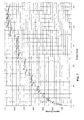
- Fig. 6 the temporal centres of gravity of all 256 video levels are shown in form of a curve for a sub-field organization with 11 sub-fields and sub-field weights as shown below: 1 2 3 5 8 12 18 27 41 58 80
- the temporal centre of gravity is calculated with the formula presented above.
- the curve in Fig. 6 is by far not monotonous and includes a lot of jumps. These jumps cause false contour effect, the gravity centered coding scheme suppress these jumps by selecting only some video levels, for which the corresponding sub-field code words have temporal centres of gravity, which will grow smoothly. This can be done by drawing a monotone curve without jumps in the previous graphic and selecting in each case the nearest point. A lot of best fitting techniques are known for this purpose from the mathematics, e.g. Gaussian fit method, which relies on minimization of the square errors. Of course, this is only one embodiment of the invention.
- An example of a monotonous curve is shown in Fig. 7 .
- the selected video levels for the sub-set of video levels are indicated with small black squares.
- a basic GCC coding has been described above.
- other embodiments may be used based on the following assumption.
- the low video level range it is not always sufficient to respect the above mentioned rule to only select those video levels where the temporal centre of gravity is smoothly growing, because in this range the number of possible levels is low and so if only growing temporal centre of gravity levels were selected, there would not be enough video levels to provide a good video quality in dark pictures, since the human eye is very sensitive in the dark video picture range.
- the false contour effect in the dark video picture range is negligible anyhow, so that it is acceptable that in this range the above-mentioned rule is violated.
- the relative video amplitude changes are low in comparison to the low or mid video level range.
- the above mentioned rule that only those video levels and corresponding sub-field code words are selected for setting up the sub-set of video levels can be revised to the less strict rule that the monotony of the curve is only required in the video level range between a first and a second limit.
- the field of possible sub-field code words is reduced by only taking the minimum weight code words (mWC).
- mWC minimum weight code words
- the numbers represent the sub-field weights.
- the video level 23 can be coded with the following codes: 0 0 0 1 0 0 1 0 0 0 0 0 1 1 0 0 0 0 1 0 0 0 0 0 0 0 1 0 1 1 0 0 0 0 0 0 0 1 1 0 0 0 0 0 0 1 1 0 0 0 0 0 0 1 1 1 0 0 0 0 0 0 1 1 1 1 0 1 0 0 0 0 0 0 0 0 0 0 0 0 0 0 0 0 0 0 0 0 0 0 0 0 0
- the selected codes also respect the rule that in each sub-field code word there should never be more than one consecutive 0 entry between two 1 entries, which means that there is never more than one inactivated sub-field between two activated sub-fields for the plasma cell addressing.
- Such codes are also called refreshing codes because the plasma cells are activated in short succession, therefore, the charge in the cell cannot vanish during a relatively long inactivated period.
- the mWC code words already respect this rule so that every video level can be used which has a corresponding mWC code word.
- the method may comprise an additional step wherein it is determined if static and moving pictures are noisy pictures or free noisy pictures and wherein, in view of the result, a specific dithering method is used. More specifically, the method of the present invention is defined as follow :
- the invention will be implemented, for example, in a PDP screen that is a progressive display with a fixed resolution.
- the GCC coding is activated (instant switch).
- the decision about no motion is filtered. This is mandatory to avoid any oscillation in the decision.
- the filtering method is illustrated in figure 9 and comprises the following steps :
- the adaptive noise dithering may use, for example, an error diffusion algorithm as described in " R.W. Floyd and L. Steinberg, Dig. Tech. Papers pp 36-37, 1975 ".
- the noise free dithering may be, for example, a 3D dithering method as described in EP No. 00 250 099.9 or in EP No. 01 250 199.5 of the same applicant.
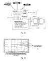
- the system comprises a Front-end IC 10.
- This IC 10 is in charge of several functions such as frame-rate conversion, format conversion, progressive conversion, video basic function.
- the front-end IC 10 receives signals from various inputs such as PC, DVD players, VCR and so on.
- the IC 10 outputs progressive signals (R, G, B) in a native format of the PDP and at the right frame rate to the dedicated plasma IC 11. It also outputs information on NOISE and MOTION.
- the dedicated Plasma IC 11 contains a lot of algorithms such as sub-field encoding (standard), gravity centered encoding (GCC), matrix and cell-based dithering, error diffusion dithering.
- the dedicated plasma IC 11 can decide which kind of algorithms should be used. As shown in figure 11 , from the IC 11, the data information as well as the scan and sustain pulses are sent to the drivers of a plasma screen 12.
- FIG. 12 represents another possible implementation.
- a microcontroller 13 is implemented between the front-end IC 10 and the dedicated plasma IC 11.
- the NOISE and MOTION information are sent to the microcontroller 13.
- the micro-controller will manage the various settings of the plasma dedicated IC while choosing between:
- the microcontroller will be in charge of the decision filtering.
- the concept is based on the split of the input pictures in various detection zones 20 as shown on figure 13 .
- the sizes as well as the number of zones are only given as example and, as known from the man skill in the art, other kinds of forms, size and number can be considered.
- a histogram of the zone will be firstly defined by choosing a number of discrete region each one defined by a lower and an upper video frontier as shown on figure 14 .
- one zone is described by a set of 8 values, each one giving the number of pixels located in a defined range (e.g. range [32; 64[). Such a histogram will be computed for each zone and memorized.
- the histogram will be compared with the corresponding histogram of the previous frame.
- a limit is set in order to decide whether there is a strong change or not. An example of decision is given below for a frame n:
- This method is based on the fact that there are a lot of similarities between two consecutive lines where only the noise makes the strongest difference.
- Noise min L (Noise(L)).
- the sub-division in segment is done by vertical lines A, A.
- the segments are shifted from one line to the other.
- the shifting may be of 1 or more pixels in the row direction as referenced by P,P'.
- some kind of overlapping between the segment should be planed to avoid any problem due to the proscan conversion or due to specific artificial test patterns. This overlapping is illustrated at the bottom of figure 16 . In this case, one line or row is common to two adjacent segments in the vertical direction.
- an additional estimation of the noise level can be performed on the inactive part of the picture.
- Such an estimation is less precise since, in case of digital pictures, the inactive part are artificially generated (e.g. DVD player).
- the figure 17 represents a typical picture sent to the plasma.
- the blanking area can have various sizes but this could be used for noise estimation.
- n analyzing regions will be defined in this blanking area called Reg(n) made of m pixels x I lines as shown on the figure 17 .
- the MSE(n) have been computed for each analyzing regions.
- a new concept is based on a histogram representation of this various MSE to extract the most accurate information.
- the overall decision for modes activating can be taken internally or can be sent to an external micro-controller as shown in figure 19 .
- the Front End IC 10' is dedicated to frame rate conversion, format conversion, progressive conversion, and video basic function. It receives input signals, for example a PC or a DVD and outputs R, G, B data to the dedicated plasma IC 11'.
- the IC 10' has no information on motion or noise.
- the dedicated plasma IC 11' is devoted to the analysis of the incoming picture. It outputs the result of the methods described above, i.e. MOTION and NOISE signals to the microcontroller 13'.
- the microcontroller will send information relating to GCC ON/OFF and to EDRD or DIT3D. So the microcontroller is in charge of the final algorithm selection as mentioned above.
- the plasma IC 11' will send data information and scan and sustain signals to the drivers of the plasma display panel 12'.
- Block(n) 1 N ⁇ Block n Pict i j t - Pict ⁇ i , j , t - 1 2 where t represents the current frame and t-1 the previous one, i and j being the horizontal and vertical position of each pixel.
- MOTION_counter When these MSE are bigger than a limit MOTION_BLOCK, a MOTION_counter will be increased: if MSE(n) ⁇ MOTION_BLOCK then MOTION_counter++, the MOTION_counter being initialized at the beginning of every frame.
- the current frame t can be compared with the previous one t-1.
- This method is based on a so-called block-matching algorithm.
- MSE ⁇ x ⁇ y n 1 N ⁇ Block n Pict i j t - Pict ⁇ i - ⁇ x , j - ⁇ y , t - 1 2 where N represents the size of the block n.
- the above method may be implemented in the system shown in figure 21 .
- the system differs from that of figure 19 in the adjunction of a frame memory 14' for storing consecutive frames (Frame t) in order to output to the plasma IC 11' the previous frame (Frame t-1).
Landscapes
- Engineering & Computer Science (AREA)
- Theoretical Computer Science (AREA)
- Physics & Mathematics (AREA)
- General Physics & Mathematics (AREA)
- Computer Hardware Design (AREA)
- Multimedia (AREA)
- Signal Processing (AREA)
- Computer Vision & Pattern Recognition (AREA)
- Control Of Indicators Other Than Cathode Ray Tubes (AREA)
- Control Of Gas Discharge Display Tubes (AREA)
- Compression Or Coding Systems Of Tv Signals (AREA)
- Liquid Crystal Display Device Control (AREA)
- Transforming Electric Information Into Light Information (AREA)
Claims (18)
- Verfahren zur Bearbeitung von Videobildern zur Wiedergabe auf einem Wiedergabegerät mit einer Vielzahl von Leuchtelementen, welche die Pixel eines Bilds bilden, wobei die Zeit eines Einzelbildes oder eines Halbbildes in eine Vielzahl von N Beleuchtungszeiträumen aufgeteilt wird, die als Sub-Felder SF bezeichnet werden, in denen die Leuchtelemente zur Lichtemission mit einer Reihe von Lichtimpulsen aktiviert werden können, welche einem Sub-Feld-Codewort entsprechen, das aus n Bits besteht und zur Kodierung der p möglichen Videopegel dient, die ein Pixel aufleuchten lassen, umfassend die folgenden Schritte:- Ermitteln, ob es sich bei den Bildern um statische Bilder oder bewegte Bilder handelt,- falls es sich um statische Bilder handelt, Bearbeiten der Videobilder unter Anwendung eines ersten Verfahrens zum Kodieren der Sub-Felder, wobei der aus n Bits bestehende Videopegel zum Aufleuchten eines Pixels in n oder mehr Sub-Zeiträume oder Sub-Felder zerlegt wird, und- falls es sich um bewegte Bilder handelt, Bearbeiten von Videobildern unter Anwendung eines zweiten Verfahrens zum Kodieren der Sub-Felder, welches den dynamischen Falschfarbeneffekt reduziert, wobei aus der Menge p möglicher Videopegel zum Aufleuchten eines Pixels eine Teilmenge von m Videopegeln mit n < m < p ausgewählt wird.
- Verfahren nach Anspruch 1, dadurch gekennzeichnet, dass es sich bei dem zweiten Verfahren zum Kodieren der Sub-Felder um ein Kodierungsverfahren handelt, bei dem jeder Videopegel der Teilmenge von m Videopegeln, die durch mindestens ein Sub-Feld-Codewort kodiert werden können, durch das Sub-Feld-Codewort kodiert wird, das unter möglichen Sub-Feld-Codewörtern den kleinsten Binärwert aufweist.
- Verfahren nach Anspruch 1, dadurch gekennzeichnet, dass es sich bei dem zweiten Verfahren zum Kodieren der Sub-Felder um ein Verfahren handelt, bei dem aus der Menge p möglicher Videopegel zum Aufleuchten eines Pixels eine Teilmenge von m Videopegeln mit n < m < p ausgewählt wird, die zur Erzeugung von Licht dient, wobei die m Werte unter Befolgung der Regel ausgewählt werden, dass der zeitliche Schwerpunkt für die Lichterzeugung mit den entsprechenden Sub-Feld-Codewörter kontinuierlich mit dem einzelnen Videopegel im unteren Videopegelbereich bis zu einem ersten festgelegten Grenzwert bzw. im oberen Videopegelbereich ab einem zweiten festgelegten Grenzwert ansteigt.
- Verfahren nach Anspruch 3, dadurch gekennzeichnet, dass der zeitliche Schwerpunkt für die Erzeugung des Lichts nach der folgenden Formel festgelegt wird:

wobei sfWl dem Sub-Feld-Gewicht des i-ten Sub-Felds entspricht, δi gleich l ist, wenn das i-te Sub-Feld aktiviert ist, und gleich Null ist, wenn das i-te Sub-Feld deaktiviert ist, und sfCGi für den zeitlichen Schwerpunkt zur Erzeugung des Lichts des i-ten Sub-Felds steht. - Verfahren nach Anspruch 3 oder 4, dadurch gekennzeichnet, dass, für den Fall, dass in einer Sub-Feld-Organisation, die durch eine bestimmte Anzahl von Sub-Feldern mit einer bestimmten Serie von Sub-Feld-Gewichten für einen Farbkomponentenwert gekennzeichnet ist, mehrere entsprechende Sub-Feld-Codewörter existieren, die Menge der möglichen Sub-Feld-Codewörter reduziert wird, indem nur die Sub-Feld-Codewörter für jeden Videopegel genommen werden, die für den Fall, dass in einem Sub-Feld-Codewort das Gewicht jedes Bits nach Größe geordnet ist, den kleinsten Binärwert aufweisen.
- Verfahren nach Anspruch 5, dadurch gekennzeichnet, dass die Auswahl von Videopegeln aus der weiter reduzierten Menge von Sub-Feld-Codewörtern dadurch erfolgt, dass für jede Gruppe von Sub-Feld-Codewörtern, die die gleiche Wurzel auf der MSB-Seite aufweisen, nur ein Videopegel genommen wird, wobei es sich bei dem nur einen Videopegel um den Videopegel handelt, der zu der nächsthöheren Gruppe von Sub-Feld-Codewörtern gehört und den kleinsten von den Schwerpunkten aufweist, die dem Schwerpunkt des zuvor ausgewählten Videopegels übergeordnet sind, wobei für den Fall, dass die nächsthöhere Gruppe von Sub-Feld-Codewörtern kein Sub-Feld-Codewort bereitstellt, das einen Schwerpunkt aufweist, der dem vorhergehenden Schwerpunkt untergeordnet ist, dann die zweite nächsthöhere Gruppe von Sub-Feld-Codewörtern für die Auswahl des nächsten Videopegels gewählt wird, und so weiter.
- Verfahren nach einem der Ansprüche 1 bis 6, dadurch gekennzeichnet, dass das Verfahren einen zusätzlichen Schritt zur Ermittlung dahingehend umfasst, ob es sich bei den statischen und bewegten Bildern um verrauschte Bilder oder rauschfreie Bilder handelt, sowie zur Verwendung einer adaptiven verrauschten Dithering-Methode für verrauschte Bilder bzw. eine rauschfreie Dithering-Methode für rauschfreie Bilder.
- Verfahren nach Anspruch 7, dadurch gekennzeichnet, dass es sich bei der adaptiven verrauschten Dithering-Methode um einen Fehlerstreuungsalgorithmus handelt.
- Verfahren nach Anspruch 7, dadurch gekennzeichnet, dass es sich bei der rauschfreien Dithering-Methode um eine 3D-Dithering-Methode handelt.
- Verfahren nach einem der Ansprüche 1 bis 9, dadurch gekennzeichnet, dass bei Vorliegen von Informationen über Bewegung die Entscheidung über eine Umschaltung zwischen dem ersten Verfahren zum Kodieren der Sub-Felder und dem zweiten Verfahren zum Kodieren der Sub-Felder angesichts der Erkennung von Bewegung nach dem folgenden Algorithmus erfolgt, in dem MOTION die Informationen über Bewegung bezeichnet, MOTION_counter einen Zähler bezeichnet und MOTION_LIMIT einen Grenzwert bezeichnet:- für jedes Einzelbild,
wenn MOTION EIN, dann MOTION_counter = 2 x MOTION_LIMIT, wenn MOTION AUS, dann MOTION_counter = MOTION_counter - 1- wenn MOTION_counter < MOTION_LIMIT, dann ist das erste Verfahren zum Kodieren der Sub-Felder aktiviert, ansonsten wird das zweite Verfahren zum Kodieren der Sub-Felder aufrecht erhalten, wobei es sich bei dem Motion-Zähler um einen Zähler handelt, der in der Lage ist, von 0 bis 2 x MOTION_LIMIT zu zählen, wenn MOTION_counter < 0, dann MOTION_counter = 0. - Verfahren nach einem der Ansprüche 1 bis 9, dadurch gekennzeichnet, dass bei Vorliegen von Informationen über Rauschen die Entscheidung über eine Umschaltung zwischen einer adaptiven verrauschten Dithering-Methode und einer rauschfreien Dithering-Methode nach dem folgenden Algorithmus erfolgt, in dem NOISE die Informationen über Rauschen bezeichnet, NOISE_counter einen Zähler bezeichnet und NOISE_LIMIT einen Grenzwert bezeichnet:- für jedes Einzelbild,
wenn NOISE EIN, dann NOISE_counter = NOISE_counter + 1, wenn NOISE AUS, dann NOISE_counter = NOISE_counter - 1,- wenn NOISE_counter > NOISE_LIMIT, ist eine aktive adaptierte verrauschte Dithering-Methode aktiviert, ansonsten wird eine rauschfreie Dithering-Methode angewendet, wobei es sich bei dem NOISE-Zähler um einen Zähler handelt, der in der Lage ist, von 0 bis 2 x NOISE_LIMIT zu zählen, wenn NOISE_counter < 0, dann NOISE_counter = 0, und wenn NOISE_counter > 2 x NOISE_LIMIT, dann NOISE_counter = 2 x NOISE_LIMIT. - Verfahren nach einem der Ansprüche 1 bis 9, dadurch gekennzeichnet, dass bei fehlendem Vorliegen von Informationen über Bewegung die Erkennung von Bewegung dadurch erfolgt, dass das folgende Verfahren angewendet wird, welches folgende Schritte umfasst:- Aufteilen des Bilds in M Erkennungszonen Z(i,j),- Berechnen eines Histogramms des Zoneninhalts für jede Erkennungszone Z(i,j),- für jede Zone Vergleichen des berechneten Histogramms mit dem entsprechenden Histogramm des vorhergehenden Bilds,- falls der Unterschied über einem vorgegebenen Grenzwert liegt, EINschalten von MOTION, wobei MOTION die Informationen über Bewegung bezeichnet.
- Verfahren nach Anspruch 12, dadurch gekennzeichnet, dass das Histogramm der Zone festgelegt wird, indem eine Anzahl diskreter Bereiche gewählt wird, die jeweils durch obere und untere Videogrenzen festgelegt sind.
- Verfahren nach einem der Ansprüche 1 bis 9, dadurch gekennzeichnet, dass bei fehlendem Vorliegen von Informationen über Rauschen das Erkennen von Rauschen mit Hilfe eines Verfahrens erfolgt, welches die folgenden Schritte umfasst:- Aufteilen des Bilds in Segmente L, die durch eine Menge von N Pixeln dargestellt werden, die aus zwei aufeinander folgenden Zeilen entnommen sind,- Berechnen eines geschätzten Rauschens für das Segment L:

wobei A(i) den Pixelwert von Pixel i in einer ersten Zeile zweier aufeinander folgender Zeilen bezeichnet und B(i) den Pixelwert von Pixel i in der zweiten Zeile der beiden aufeinander folgenden Zeilen bezeichnet, wobei i∈[1,N] ,- Festlegen des geschätzten Rauschens für das gesamte Bild als Mindestwert des geschätzten Rauschens Noise = minL (Noise (L)),- und Vergleichen des Werts Noise mit einem Schwellenwert, um zu ermitteln, ob Noise EIN oder AUS ist. - Verfahren nach einem der Ansprüche 1 bis 9, dadurch gekennzeichnet, dass bei fehlendem Vorliegen von Informationen über Rauschen das Erkennen von Rauschen mit Hilfe des folgenden Verfahrens erfolgt:- Festlegen einer Austastfläche eines Bilds, n' Bereiche Reg(n'), die aus m Pixeln x l Zeilen bestehen,- Berechnen der Mittelwerte jedes Bereichs anhand der folgenden Formel:

wobei i und j für die verschiedenen horizontalen und vertikalen Pixelpositionen jedes Bereichs stehen,- Berechnen des statistischen Gesamtfehlers für jeden Bereich: - danach Schätzen des endgültigen Rauschens des gesamten Bilds.
 - Anordnung, umfassend alle Mittel für die Anwendung des Verfahrens nach einem der Ansprüche 1 bis 15, gekennzeichnet durch eine integrierte Eingangsschaltung (10), die Videobilder empfängt und erkennt, ob es sich bei den Videobildern um statische oder bewegte Bilder handelt, eine integrierte Schaltung (11) zum Kodieren der statischen Bilder unter Anwendung eines ersten Verfahrens zum Kodieren der Sub-Felder, wobei der aus n Bits bestehende Videopegel in n oder mehr Sub-Zeiträume oder Sub-Felder zerlegt wird, um für Bilder, in denen keine Bewegung erkannt wird, ein Pixel aufleuchten zu lassen, und um die bewegten Bilder unter Anwendung eines zweiten Verfahrens zum Kodieren der Sub-Felder zu kodieren, wobei aus der Menge p möglicher Videopegel zum Aufleuchten eines Pixels eine Teilmenge von m Videopegeln mit n < m < p ausgewählt wird, um den dynamischen Falschfarbeneffekt bei Bildern, in denen Bewegung erkannt wird, zu reduzieren, und um Dateninformationen und Steuersignale an Treiber eines Plasmaanzeigefelds (12) zu liefern.
- Anordnung, umfassend alle Mittel für die Anwendung des Verfahrens nach einem der Ansprüche 1 bis 9 und 12 bis 15, gekennzeichnet durch eine integrierte Eingangsschaltung (10), die Videobilder empfängt und keine Informationen über Rauschen und Bewegung liefert, eine integrierte Schaltung (11) in Kombination mit einem Microcontroller (13), um zu erkennen, ob es sich bei den Videobildern um statische oder bewegliche Bilder handelt, die statischen Bilder unter Anwendung des ersten Verfahrens zum Kodieren der Sub-Felder zu kodieren und die bewegten Bilder unter Anwendung des zweiten Verfahrens zum Kodieren der Sub-Felder zu kodieren, was den dynamischen Falschfarbeneffekt reduziert, und um Dateninformationen und Steuersignale an Treiber eines Plasmaanzeigefelds (12) zu liefern.
- Anordnung nach Anspruch 16, wobei für den Fall, dass mehrere entsprechende Sub-Feld-Codewörter existieren, die Menge der möglichen Sub-Feld-Codewörter reduziert wird, indem nur die Sub-Feld-Codewörter für jeden Videopegel genommen werden, die den kleinsten Binärwert aufweisen.
Priority Applications (1)
| Application Number | Priority Date | Filing Date | Title |
|---|---|---|---|
| EP03761583.8A EP1532607B1 (de) | 2002-06-28 | 2003-06-17 | Verfahren und vorrichtung zur bearbeitung von videobildern zurverbesserten kompensation des dynamischen falschfarbeneffekts |
Applications Claiming Priority (4)
| Application Number | Priority Date | Filing Date | Title |
|---|---|---|---|
| EP02291612 | 2002-06-28 | ||
| EP02291612A EP1376521A1 (de) | 2002-06-28 | 2002-06-28 | Videobildbearbeitung zur verbesserten Kompensation des dynamischen Falschkontureffekts |
| EP03761583.8A EP1532607B1 (de) | 2002-06-28 | 2003-06-17 | Verfahren und vorrichtung zur bearbeitung von videobildern zurverbesserten kompensation des dynamischen falschfarbeneffekts |
| PCT/EP2003/050232 WO2004003881A1 (en) | 2002-06-28 | 2003-06-17 | Method and apparatus for processing video pictures improving dynamic false contour effect compensation |
Publications (2)
| Publication Number | Publication Date |
|---|---|
| EP1532607A1 EP1532607A1 (de) | 2005-05-25 |
| EP1532607B1 true EP1532607B1 (de) | 2015-10-21 |
Family
ID=29716957
Family Applications (2)
| Application Number | Title | Priority Date | Filing Date |
|---|---|---|---|
| EP02291612A Withdrawn EP1376521A1 (de) | 2002-06-28 | 2002-06-28 | Videobildbearbeitung zur verbesserten Kompensation des dynamischen Falschkontureffekts |
| EP03761583.8A Expired - Lifetime EP1532607B1 (de) | 2002-06-28 | 2003-06-17 | Verfahren und vorrichtung zur bearbeitung von videobildern zurverbesserten kompensation des dynamischen falschfarbeneffekts |
Family Applications Before (1)
| Application Number | Title | Priority Date | Filing Date |
|---|---|---|---|
| EP02291612A Withdrawn EP1376521A1 (de) | 2002-06-28 | 2002-06-28 | Videobildbearbeitung zur verbesserten Kompensation des dynamischen Falschkontureffekts |
Country Status (7)
| Country | Link |
|---|---|
| US (1) | US7339632B2 (de) |
| EP (2) | EP1376521A1 (de) |
| JP (1) | JP5010099B2 (de) |
| CN (1) | CN100458883C (de) |
| AU (1) | AU2003254499A1 (de) |
| TW (1) | TWI226796B (de) |
| WO (1) | WO2004003881A1 (de) |
Families Citing this family (43)
| Publication number | Priority date | Publication date | Assignee | Title |
|---|---|---|---|---|
| KR100550984B1 (ko) * | 2003-11-28 | 2006-02-13 | 삼성에스디아이 주식회사 | 플라즈마 디스플레이 패널의 구동 장치, 플라즈마디스플레이 패널의 화상 처리 방법 및 플라즈마디스플레이 패널 |
| EP1544836A1 (de) * | 2003-12-17 | 2005-06-22 | Deutsche Thomson-Brandt GmbH | Verfahren und Vorrichtung zur Vorbehandlung von Film-Mode Videofelder beinhaltenden Video Daten |
| KR20050091509A (ko) * | 2004-03-12 | 2005-09-15 | 삼성전자주식회사 | 디스플레이장치 |
| JP4886992B2 (ja) * | 2004-03-16 | 2012-02-29 | パナソニック株式会社 | 画像処理装置、表示装置、画像処理方法及びプログラム |
| KR100571201B1 (ko) | 2004-05-21 | 2006-04-17 | 엘지전자 주식회사 | 하프톤 노이즈를 감소시킬 수 있는 플라즈마 표시 패널의구동 장치 및 구동 방법 |
| KR100627297B1 (ko) * | 2005-01-12 | 2006-09-25 | 삼성에스디아이 주식회사 | 플라즈마 표시 장치 및 그 화상 처리 방법 |
| JP2007101960A (ja) * | 2005-10-05 | 2007-04-19 | Fujitsu Hitachi Plasma Display Ltd | デジタル表示装置の表示方法及びデジタル表示装置 |
| ATE488835T1 (de) | 2005-12-22 | 2010-12-15 | Imaging Systems Technology Inc | Sas-adressierung einer ac-plasmaanzeige mit oberflächenentladung |
| EP2002418A1 (de) * | 2006-04-03 | 2008-12-17 | Thomson Licensing | Verfahren und vorrichtung zur kodierung von videoebenen bei einer plasmaanzeigevorrichtung |
| EP1845509A1 (de) | 2006-04-11 | 2007-10-17 | Deutsche Thomson-Brandt Gmbh | Verfahren und Vorrichtung zur bewegungsabhängigen Kodierung |
| US9198084B2 (en) | 2006-05-26 | 2015-11-24 | Qualcomm Incorporated | Wireless architecture for a traditional wire-based protocol |
| US8532375B2 (en) * | 2007-01-19 | 2013-09-10 | Thomson Licensing | Identifying banding in digital images |
| WO2009032255A2 (en) * | 2007-09-04 | 2009-03-12 | The Regents Of The University Of California | Hierarchical motion vector processing method, software and devices |
| CN101753908B (zh) * | 2008-12-02 | 2011-07-20 | 青岛海信电器股份有限公司 | 一种适用于pdp的动画显示方法及pdp电视机 |
| US9398089B2 (en) | 2008-12-11 | 2016-07-19 | Qualcomm Incorporated | Dynamic resource sharing among multiple wireless devices |
| US9264248B2 (en) | 2009-07-02 | 2016-02-16 | Qualcomm Incorporated | System and method for avoiding and resolving conflicts in a wireless mobile display digital interface multicast environment |
| JPWO2011045924A1 (ja) * | 2009-10-13 | 2013-03-04 | パナソニック株式会社 | プラズマディスプレイ装置の駆動方法、プラズマディスプレイ装置およびプラズマディスプレイシステム |
| US9582238B2 (en) | 2009-12-14 | 2017-02-28 | Qualcomm Incorporated | Decomposed multi-stream (DMS) techniques for video display systems |
| CN101887680B (zh) * | 2009-12-25 | 2012-05-30 | 四川虹欧显示器件有限公司 | 降低动态伪轮廓的方法及系统 |
| TWI563479B (en) * | 2009-12-30 | 2016-12-21 | Tatung Co | Field emission display |
| CN101887679B (zh) * | 2009-12-31 | 2012-05-30 | 四川虹欧显示器件有限公司 | 降低动态伪轮廓的方法及系统 |
| US10135900B2 (en) | 2011-01-21 | 2018-11-20 | Qualcomm Incorporated | User input back channel for wireless displays |
| US9065876B2 (en) | 2011-01-21 | 2015-06-23 | Qualcomm Incorporated | User input back channel from a wireless sink device to a wireless source device for multi-touch gesture wireless displays |
| US8964783B2 (en) | 2011-01-21 | 2015-02-24 | Qualcomm Incorporated | User input back channel for wireless displays |
| US9413803B2 (en) | 2011-01-21 | 2016-08-09 | Qualcomm Incorporated | User input back channel for wireless displays |
| US9787725B2 (en) | 2011-01-21 | 2017-10-10 | Qualcomm Incorporated | User input back channel for wireless displays |
| US20130013318A1 (en) | 2011-01-21 | 2013-01-10 | Qualcomm Incorporated | User input back channel for wireless displays |
| US9503771B2 (en) | 2011-02-04 | 2016-11-22 | Qualcomm Incorporated | Low latency wireless display for graphics |
| US10108386B2 (en) | 2011-02-04 | 2018-10-23 | Qualcomm Incorporated | Content provisioning for wireless back channel |
| US8659701B2 (en) * | 2011-12-19 | 2014-02-25 | Sony Corporation | Usage of dither on interpolated frames |
| US9525998B2 (en) | 2012-01-06 | 2016-12-20 | Qualcomm Incorporated | Wireless display with multiscreen service |
| EP3069513B1 (de) | 2013-11-12 | 2019-03-13 | Dolby Laboratories Licensing Corporation | Vorab-dithering in einer bildcodierung mit hohem dynamikumfang |
| JP6643230B2 (ja) * | 2014-07-11 | 2020-02-12 | ソニーセミコンダクタソリューションズ株式会社 | 画像処理装置、撮像装置、画像処理方法、および、プログラム |
| TWI563495B (en) * | 2014-11-05 | 2016-12-21 | Jadard Technology Inc | Display device and image segment adjustment method thereof |
| CN105741747A (zh) * | 2014-12-08 | 2016-07-06 | 王丽香 | 一种提升pdp图像灰阶质量且降低显示功耗的方法 |
| CN105741746A (zh) * | 2014-12-08 | 2016-07-06 | 王丽香 | 一种改善pdp显示器高温误放电的驱动波形 |
| CN106057167B (zh) * | 2016-07-21 | 2019-04-05 | 京东方科技集团股份有限公司 | 一种对文字边缘暗化处理的方法及装置 |
| EP3316578A1 (de) | 2016-10-25 | 2018-05-02 | Thomson Licensing | Verfahren und vorrichtung zur codierung und decodierung eines bildes |
| CN107665666B (zh) * | 2017-10-31 | 2019-10-01 | 京东方科技集团股份有限公司 | 显示模组的伽马电压校正方法及系统 |
| JP7283487B2 (ja) * | 2019-01-25 | 2023-05-30 | 株式会社ソシオネクスト | 制御装置、制御方法及び表示システム |
| CN110248132B (zh) * | 2019-05-31 | 2020-12-01 | 成都东方盛行电子有限责任公司 | 一种视频帧率插值方法 |
| WO2022030133A1 (ja) * | 2020-08-07 | 2022-02-10 | ソニーセミコンダクタソリューションズ株式会社 | 駆動回路 |
| CN113099308B (zh) * | 2021-03-31 | 2023-10-27 | 聚好看科技股份有限公司 | 一种内容显示方法、显示设备及图像采集器 |
Family Cites Families (17)
| Publication number | Priority date | Publication date | Assignee | Title |
|---|---|---|---|---|
| JPH1039831A (ja) * | 1996-07-22 | 1998-02-13 | Matsushita Electric Ind Co Ltd | ディスプレイの駆動回路と表示装置 |
| WO1998044479A1 (en) * | 1997-03-31 | 1998-10-08 | Matsushita Electric Industrial Co., Ltd. | Dynamic image display method and device therefor |
| JPH10307561A (ja) * | 1997-05-08 | 1998-11-17 | Mitsubishi Electric Corp | プラズマディスプレイパネルの駆動方法 |
| JP3577888B2 (ja) * | 1997-05-19 | 2004-10-20 | 松下電器産業株式会社 | 多階調画像表示装置 |
| JP3414265B2 (ja) * | 1997-11-18 | 2003-06-09 | 松下電器産業株式会社 | 多階調画像表示装置 |
| JP2994634B2 (ja) * | 1997-12-10 | 1999-12-27 | 松下電器産業株式会社 | 表示装置 |
| JPH11231831A (ja) * | 1998-02-13 | 1999-08-27 | Samson Yokohama Kenkyusho:Kk | プラズマディスプレイ装置の駆動方法 |
| FR2776414B1 (fr) * | 1998-03-23 | 2000-05-12 | Thomson Multimedia Sa | Procede et dispositif pour adressage de panneaux a plasma |
| EP0978816B1 (de) * | 1998-08-07 | 2002-02-13 | Deutsche Thomson-Brandt Gmbh | Verfahren und Vorrichtung zur Videobildbearbeitung, insbesondere zur Kompensation des Falschkontureffekts |
| EP0978817A1 (de) * | 1998-08-07 | 2000-02-09 | Deutsche Thomson-Brandt Gmbh | Verfahren und Vorrichtung zur Bearbeitung von Videobildern, insbesondere zur Kompensation des Falschkontureffekts |
| FR2785076B1 (fr) * | 1998-10-23 | 2002-11-15 | Thomson Multimedia Sa | Procede d'adressage pour ecran a plasma base sur un adressage separe des lignes paires et impaires |
| JP3457251B2 (ja) * | 1999-04-12 | 2003-10-14 | 松下電器産業株式会社 | 画像表示装置 |
| EP1049068A1 (de) * | 1999-04-28 | 2000-11-02 | THOMSON multimedia S.A. | Verfahren und Vorrichtung zur Videosignalverarbeitung |
| AU7783900A (en) | 1999-09-29 | 2001-04-30 | Thomson Licensing S.A. | Data processing method and apparatus for a display device |
| DE60010063T2 (de) * | 2000-06-09 | 2004-08-19 | Deutsche Thomson-Brandt Gmbh | Verfahren und Vorrichtung zur Videobildbearbeitung zur Kompensation des Falschkontureffekts |
| EP1172765A1 (de) * | 2000-07-12 | 2002-01-16 | Deutsche Thomson-Brandt Gmbh | Verfahren und Vorrichtung zur Verarbeitung von Videobildern |
| EP1207510A1 (de) * | 2000-11-18 | 2002-05-22 | Deutsche Thomson-Brandt Gmbh | Verfahren und Vorrichtung zur Bearbeitung von Videobildern |
-
2002
- 2002-06-28 EP EP02291612A patent/EP1376521A1/de not_active Withdrawn
-
2003
- 2003-06-17 WO PCT/EP2003/050232 patent/WO2004003881A1/en not_active Ceased
- 2003-06-17 AU AU2003254499A patent/AU2003254499A1/en not_active Abandoned
- 2003-06-17 EP EP03761583.8A patent/EP1532607B1/de not_active Expired - Lifetime
- 2003-06-17 JP JP2004516777A patent/JP5010099B2/ja not_active Expired - Fee Related
- 2003-06-17 CN CNB03814638XA patent/CN100458883C/zh not_active Expired - Fee Related
- 2003-06-17 US US10/518,583 patent/US7339632B2/en not_active Expired - Lifetime
- 2003-06-20 TW TW092116730A patent/TWI226796B/zh not_active IP Right Cessation
Also Published As
| Publication number | Publication date |
|---|---|
| AU2003254499A1 (en) | 2004-01-19 |
| EP1376521A1 (de) | 2004-01-02 |
| US20050253972A1 (en) | 2005-11-17 |
| TW200400756A (en) | 2004-01-01 |
| WO2004003881A1 (en) | 2004-01-08 |
| TWI226796B (en) | 2005-01-11 |
| JP5010099B2 (ja) | 2012-08-29 |
| JP2005531799A (ja) | 2005-10-20 |
| CN100458883C (zh) | 2009-02-04 |
| WO2004003881A8 (en) | 2005-03-17 |
| CN1662944A (zh) | 2005-08-31 |
| EP1532607A1 (de) | 2005-05-25 |
| US7339632B2 (en) | 2008-03-04 |
Similar Documents
| Publication | Publication Date | Title |
|---|---|---|
| US7339632B2 (en) | Method and apparatus for processing video pictures improving dynamic false contour effect compensation | |
| US6476875B2 (en) | Method and apparatus for processing video pictures, especially for false contour effect compensation | |
| US6473464B1 (en) | Method and apparatus for processing video pictures, especially for false contour effect compensation | |
| KR100670986B1 (ko) | 디스플레이 구동 방법 | |
| AU785352B2 (en) | Method and apparatus for processing video pictures | |
| JP4928662B2 (ja) | 表示装置に表示するためにビデオ画像を処理する方法及び装置 | |
| US7023450B1 (en) | Data processing method and apparatus for a display device | |
| KR100869656B1 (ko) | 서브-필드에서 이미지를 디스플레이하는 방법 및 유닛 | |
| KR100887678B1 (ko) | 비디오 화상을 처리하기 위한 방법 및 비디오 화상을처리하기 위한 장치 | |
| EP1162571A1 (de) | Verfahren und Vorrichtung zur Videobildbearbeitung, insbesondere zur Kompensation des Falschkontureffekts | |
| EP0980059B1 (de) | Verfahren und Vorrichtung zur Bearbeitung von Videobildern, insbesondere zur Kompensation des Falschkontureffekts | |
| KR100946737B1 (ko) | 비디오 화상을 처리하기 위한 방법 및 그 방법을 구현하기 위한 시스템 | |
| US6882115B2 (en) | Method and apparatus of processing video signal in plasma display panel | |
| EP0987675A1 (de) | Vorrichtung und Verfahren zur Video-Bildbearbeitung, insbesondere zur Kompensation des Falschkontureneffekts |
Legal Events
| Date | Code | Title | Description |
|---|---|---|---|
| PUAI | Public reference made under article 153(3) epc to a published international application that has entered the european phase |
Free format text: ORIGINAL CODE: 0009012 |
|
| 17P | Request for examination filed |
Effective date: 20050124 |
|
| AK | Designated contracting states |
Kind code of ref document: A1 Designated state(s): AT BE BG CH CY CZ DE DK EE ES FI FR GB GR HU IE IT LI LU MC NL PT RO SE SI SK TR |
|
| AX | Request for extension of the european patent |
Extension state: AL LT LV MK |
|
| RAP1 | Party data changed (applicant data changed or rights of an application transferred) |
Owner name: THOMSON LICENSING |
|
| DAX | Request for extension of the european patent (deleted) | ||
| RBV | Designated contracting states (corrected) |
Designated state(s): AT BE BG DE FR GB |
|
| RIN1 | Information on inventor provided before grant (corrected) |
Inventor name: WEITBRUCH, SEBASTIEN Inventor name: THEBAULT, CEDRIC Inventor name: DOSER, INGO Inventor name: CORREA, CARLOS |
|
| 17Q | First examination report despatched |
Effective date: 20070525 |
|
| RAP1 | Party data changed (applicant data changed or rights of an application transferred) |
Owner name: THOMSON LICENSING |
|
| REG | Reference to a national code |
Ref country code: DE Ref legal event code: R079 Ref document number: 60348167 Country of ref document: DE Free format text: PREVIOUS MAIN CLASS: G09G0003280000 Ipc: H04N0005213000 |
|
| RIC1 | Information provided on ipc code assigned before grant |
Ipc: H04N 5/213 20060101AFI20150122BHEP |
|
| GRAP | Despatch of communication of intention to grant a patent |
Free format text: ORIGINAL CODE: EPIDOSNIGR1 |
|
| INTG | Intention to grant announced |
Effective date: 20150311 |
|
| RBV | Designated contracting states (corrected) |
Designated state(s): DE FR GB |
|
| GRAP | Despatch of communication of intention to grant a patent |
Free format text: ORIGINAL CODE: EPIDOSNIGR1 |
|
| INTG | Intention to grant announced |
Effective date: 20150810 |
|
| GRAS | Grant fee paid |
Free format text: ORIGINAL CODE: EPIDOSNIGR3 |
|
| GRAA | (expected) grant |
Free format text: ORIGINAL CODE: 0009210 |
|
| AK | Designated contracting states |
Kind code of ref document: B1 Designated state(s): DE FR GB |
|
| REG | Reference to a national code |
Ref country code: GB Ref legal event code: FG4D |
|
| REG | Reference to a national code |
Ref country code: DE Ref legal event code: R084 Ref document number: 60348167 Country of ref document: DE |
|
| REG | Reference to a national code |
Ref country code: DE Ref legal event code: R096 Ref document number: 60348167 Country of ref document: DE |
|
| REG | Reference to a national code |
Ref country code: FR Ref legal event code: PLFP Year of fee payment: 14 |
|
| REG | Reference to a national code |
Ref country code: DE Ref legal event code: R097 Ref document number: 60348167 Country of ref document: DE |
|
| PLBE | No opposition filed within time limit |
Free format text: ORIGINAL CODE: 0009261 |
|
| STAA | Information on the status of an ep patent application or granted ep patent |
Free format text: STATUS: NO OPPOSITION FILED WITHIN TIME LIMIT |
|
| 26N | No opposition filed |
Effective date: 20160722 |
|
| REG | Reference to a national code |
Ref country code: FR Ref legal event code: PLFP Year of fee payment: 15 |
|
| REG | Reference to a national code |
Ref country code: DE Ref legal event code: R082 Ref document number: 60348167 Country of ref document: DE Representative=s name: DEHNS, DE Ref country code: DE Ref legal event code: R082 Ref document number: 60348167 Country of ref document: DE Representative=s name: DEHNS PATENT AND TRADEMARK ATTORNEYS, DE Ref country code: DE Ref legal event code: R082 Ref document number: 60348167 Country of ref document: DE Representative=s name: HOFSTETTER, SCHURACK & PARTNER PATENT- UND REC, DE |
|
| REG | Reference to a national code |
Ref country code: FR Ref legal event code: PLFP Year of fee payment: 16 |
|
| REG | Reference to a national code |
Ref country code: DE Ref legal event code: R082 Ref document number: 60348167 Country of ref document: DE Representative=s name: DEHNS, DE Ref country code: DE Ref legal event code: R081 Ref document number: 60348167 Country of ref document: DE Owner name: INTERDIGITAL CE PATENT HOLDINGS SAS, FR Free format text: FORMER OWNER: THOMSON LICENSING, ISSY-LES-MOULINEAUX, FR Ref country code: DE Ref legal event code: R082 Ref document number: 60348167 Country of ref document: DE Representative=s name: DEHNS PATENT AND TRADEMARK ATTORNEYS, DE |
|
| REG | Reference to a national code |
Ref country code: GB Ref legal event code: 732E Free format text: REGISTERED BETWEEN 20190926 AND 20191002 |
|
| PGFP | Annual fee paid to national office [announced via postgrant information from national office to epo] |
Ref country code: FR Payment date: 20200626 Year of fee payment: 18 |
|
| PGFP | Annual fee paid to national office [announced via postgrant information from national office to epo] |
Ref country code: GB Payment date: 20200630 Year of fee payment: 18 |
|
| PGFP | Annual fee paid to national office [announced via postgrant information from national office to epo] |
Ref country code: DE Payment date: 20200630 Year of fee payment: 18 |
|
| REG | Reference to a national code |
Ref country code: DE Ref legal event code: R119 Ref document number: 60348167 Country of ref document: DE |
|
| GBPC | Gb: european patent ceased through non-payment of renewal fee |
Effective date: 20210617 |
|
| PG25 | Lapsed in a contracting state [announced via postgrant information from national office to epo] |
Ref country code: GB Free format text: LAPSE BECAUSE OF NON-PAYMENT OF DUE FEES Effective date: 20210617 Ref country code: DE Free format text: LAPSE BECAUSE OF NON-PAYMENT OF DUE FEES Effective date: 20220101 |
|
| PG25 | Lapsed in a contracting state [announced via postgrant information from national office to epo] |
Ref country code: FR Free format text: LAPSE BECAUSE OF NON-PAYMENT OF DUE FEES Effective date: 20210630 |