EP1532502B1 - Boitier de manoeuvre pour la commande d'un actionneur - Google Patents
Boitier de manoeuvre pour la commande d'un actionneur Download PDFInfo
- Publication number
- EP1532502B1 EP1532502B1 EP03738834A EP03738834A EP1532502B1 EP 1532502 B1 EP1532502 B1 EP 1532502B1 EP 03738834 A EP03738834 A EP 03738834A EP 03738834 A EP03738834 A EP 03738834A EP 1532502 B1 EP1532502 B1 EP 1532502B1
- Authority
- EP
- European Patent Office
- Prior art keywords
- lid
- maneuver box
- handles
- control devices
- box according
- Prior art date
- Legal status (The legal status is an assumption and is not a legal conclusion. Google has not performed a legal analysis and makes no representation as to the accuracy of the status listed.)
- Expired - Lifetime
Links
- 230000008878 coupling Effects 0.000 description 19
- 238000010168 coupling process Methods 0.000 description 19
- 238000005859 coupling reaction Methods 0.000 description 19
- 230000006378 damage Effects 0.000 description 4
- 230000001681 protective effect Effects 0.000 description 4
- 239000002184 metal Substances 0.000 description 3
- 210000005069 ears Anatomy 0.000 description 2
- 230000000717 retained effect Effects 0.000 description 2
- 231100001261 hazardous Toxicity 0.000 description 1
- 239000000463 material Substances 0.000 description 1
- 210000002445 nipple Anatomy 0.000 description 1
- 239000012858 resilient material Substances 0.000 description 1
Images


Classifications
-
- G—PHYSICS
- G05—CONTROLLING; REGULATING
- G05G—CONTROL DEVICES OR SYSTEMS INSOFAR AS CHARACTERISED BY MECHANICAL FEATURES ONLY
- G05G5/00—Means for preventing, limiting or returning the movements of parts of a control mechanism, e.g. locking controlling member
- G05G5/28—Means for preventing, limiting or returning the movements of parts of a control mechanism, e.g. locking controlling member for preventing unauthorised access to the controlling member or its movement to a command position
-
- B—PERFORMING OPERATIONS; TRANSPORTING
- B60—VEHICLES IN GENERAL
- B60D—VEHICLE CONNECTIONS
- B60D1/00—Traction couplings; Hitches; Draw-gear; Towing devices
- B60D1/24—Traction couplings; Hitches; Draw-gear; Towing devices characterised by arrangements for particular functions
- B60D1/28—Traction couplings; Hitches; Draw-gear; Towing devices characterised by arrangements for particular functions for preventing unwanted disengagement, e.g. safety appliances
-
- B—PERFORMING OPERATIONS; TRANSPORTING
- B60—VEHICLES IN GENERAL
- B60D—VEHICLE CONNECTIONS
- B60D1/00—Traction couplings; Hitches; Draw-gear; Towing devices
- B60D1/58—Auxiliary devices
- B60D1/60—Covers, caps or guards, e.g. comprising anti-theft devices
Definitions
- the invention relates to a maneuver box which comprises one or more control devices communicating with at least one remotely located power actuator, a base unit rigidly secured to a larger structure and supporting rigidly the control device or devices, and a lid pivotally hinged on the base unit and movable between an open position and a closed position in which it covers and protects the control device or devices, whereby handles are provided for shifting each control device between two or more operating positions, one of which is a safety position.
- the main object of the invention is to provide an improved maneuver box which not only provides a good protection for the control devices, which is important in rough environments such as underneath a truck chassis, but enhances safety by ensuring that the control devices are put in their safety positions before the protective box lid can be closed.
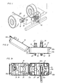
- Fig. 1 there is illustrated the rear end of a truck provided with a mechanised coupling 10 for connection of the tow bar of a trailer (not shown).
- the coupling 10 is provided with a remotely controlled pneumatic actuator 11 for operating the lock bolt of the coupling, between a tow bar locking position and a tow bar releasing position.
- the lock bolt is retained in its tow bar releasing position by a latch mechanism which is arranged to be tripped by the tow bar as the latter is properly inserted into the coupling.
- the lock bolt is maintained in closed position by a continuously acting air pressure, and in another type the lock bolt is maintained in closed position by a second latch mechanism. The operation order of the coupling will be described briefly below.
- the pneumatic actuator 11 is operated by a control valve 14 and a shut-off valve 15 which are both mounted in a maneuver box B disposed at a distance from the actuator 11.
- the maneuver box B comprises a base unit 17 which via a bottom section 16 is secured to a part 18 of the frame work of the truck.
- the base unit 17 comprises two side walls 12a,b and two end walls 13a,b, and a protective lid 19 is hinged at one of the end walls 13a for movement between a closed position and an open position.
- the shut-off valve 15 is arranged to open or shut the pressure air supply to the control valve 14 and also to depressurise the actuator 11 in its closed position.
- the shut-off valve 14 is provided with a short handle 27 which is shiftable over 90 degrees between a closed position as shown in Figs. 2,3a,3b,3c and an open position as shown in Figs. 6,7.
- the control valve 14 is arranged to feed pressure air to either sides of the actuator 11 to accomplish lifting and lowering, respectively, of the lock bolt of the coupling 10.
- the control valve 15 is provided a foldable handle 28 including a pivotal lever 29. See Figs. 4,5.
- the shut-off valve 15 is put in its open position to deliver pressure air to the control valve 14.
- the control valve 14 is shifted to a first position, see Fig. 3b, to supply pressure air to one end of the actuator 11, thereby accomplishing lifting of the lock bolt to an open position.
- the lock bolt is retained by the latch mechanism in its open position.
- the control valve 11 supplies pressure air to the opposite end of the actuator 11 to make the latter apply a closing force on the lock bolt of the coupling 10.
- the air pressure related force on the lock bolt acts to lowering the lock bolt and closing the coupling 10.
- the lid 19 is intended to close tightly the maneuver box B so as to protect the valves 14,15 against damage and dirt, and to prevent unintentional movement and shifting of the valves 14,15.
- the lid 19 is provided with a lock device in the form of a friction retainer and/or ears 30a,30b for a pad lock so as to be safely maintained in closed position.
- the friction retainer comprises a block 31 of a resilient material mounted on the lid 19 and formed with a recess 32 at its outer end for engaging a stud member 33 on the base unit 17.
- the shut-off valve 15 and the control valve 14 have specific safety positions in which the valves should be maintained when the coupling 10 is not to be operated.
- the shut-off valve 15 has a safety position equal to the closed position, i.e. the handle 27 shall be put on a transverse position relative to the side walls 12a,b.
- the safety position of the control valve 14 means that the handle 28 shall be maintained in a position transverse to the side walls 12a,b.
- These positions are safety positions for the valves 14,15, i.e. positions that guarantees that the coupling 10 is safely maintained in its closed position.
- the lid 19 is provided with a three dimensional structure on the inside such that the lid can not be closed unless the valves 14,15 and their handles 27,28 are put in their respective safety positions.
- this three dimensional structure comprises sheet metal profiles which would cross the handles 27,28 if the valves 14,15 are not in their correct position.
- a second X-shaped sheet metal profile 36 is mounted between the transverse profile 34 and an end wall of the lid 19, and in the example illustrated in Figs. 3a-c, this X-shaped profile 36 is formed with transversely extending recesses 37,38 to accommodate the shut-off valve handle 27 when occupying the transverse safety position. These recesses 37,38 also lock the handle 27 in the safety position such that any unintentional movement of the shut-off valve 15 is prevented.
- the X-shaped profile 36 is provided with recesses 40,41 extending, when the lid 19 is closed, in parallel with the side walls 12a,b of the base unit 17.
- These recesses 40,41 are arranged to accommodate and lock the handle 27 in the safety position of that example, namely in parallel with the side walls 12a,b of the base unit 17.
- valves 14,15 As the coupling 10 has been operated via the valves 14,15 to connect or disconnect a trailer to the truck the lid 19 is closed and locked, either by the friction retainer 31 only or by a pad lock engaging the ears 30a,30b. Thereby, the valves 14,15 are protected not only from damage and dirt but also from unauthorised or unintentional shifting.
- the maneuver box B according to the invention is specifically designed to match the shapes and locations of the control devices fitted in a particular application, and the invention is not limited to the shown and described examples but can be freely varied within the scope of the claims. Accordingly, the invention is not limited to the use of a pneumatic valves. Alternatively, the maneuver box may be as well used for hydraulic or electric control devices.
Landscapes
- Engineering & Computer Science (AREA)
- Transportation (AREA)
- Mechanical Engineering (AREA)
- Computer Security & Cryptography (AREA)
- Physics & Mathematics (AREA)
- General Physics & Mathematics (AREA)
- Automation & Control Theory (AREA)
- Pressure Vessels And Lids Thereof (AREA)
- Lock And Its Accessories (AREA)
- Preventing Unauthorised Actuation Of Valves (AREA)
Claims (7)
- Boîtier de manoeuvre comprenant un ou plusieurs dispositifs de commande (14, 15) destinés à la communication avec au moins un actionneur électrique à distance (11), comprenant
une unité de base (17) fixée de manière rigide à une structure plus grande (18) et supportant de manière rigide le dispositif ou plusieurs dispositifs de commande (14, 15), et
un couvercle (19) articulé, pouvant pivoter sur l'unité de base (17) pour se déplacer entre une position ouverte et une position fermée, recouvrant et protégeant les dispositifs de commande (14, 15),
les dispositifs de commande (14, 15) comprenant des poignées (27, 28) accessibles dans la position ouverte du couvercle (19) pour le déplacement manuel de chacun des dispositifs de commande (14, 15) entre deux positions de fonctionnement ou plus, l'une des positions de fonctionnement étant une position de sécurité
caractérisé en ce que
le couvercle (19) est une structure interne à trois dimensions (34, 36) adaptée à recevoir les poignées (27, 28) et à permettre la fermeture du couvercle (19) uniquement lorsque chacune des poignées (27, 28) occupe sa position de sécurité. - Boîtier de manoeuvre selon la revendication 1, dans lequel la structure en trois dimensions (33, 36) comprend un ou plusieurs éléments de paroi (34, 36) situés sur l'intérieur du couvercle (19) et constituant des creux (35, 37, 38, 40, 41) destinés à recevoir les poignées (27, 28).
- Boîtier de manoeuvre selon la revendication 1 ou 2, dans lequel les creux (35, 37, 38, 40, 41) permettant le verrouillage des poignées (27, 28) dans les positions de sécurité.
- Boîtier de manoeuvre selon l'une des revendications 1 à 3, dans lequel au moins l'une des poignées (28) comprend un levier pliable (29) qui s'étend en dehors de l'unité de base (17) lorsqu'il est déplié.
- Agencement comprenant un boîtier de manoeuvre selon l'une des revendications 1 à 4 l'actionneur électrique (11) étant actionné pneumatiquement, les dispositifs de commande (14, 15) comprenant une vanne d'alimentation d'air sous pression (15) et une vanne directionnelle (14) qui contrôlent toutes deux la communication d'air sous pression avec l'actionneur électrique (11).
- Boîtier de manoeuvre selon l'une des revendications 1 à 5, dans lequel l'unité de base (17) et le couvercle (19) sont dotés de moyens de verrouillage coopérants (31, 32, 33 ; 30a, 30b) destinés à maintenir le couvercle (19) dans la position fermée.
- Utilisation d'un boîtier de manoeuvre selon l'une des revendications 1 à 6, dans lequel l'actionneur électrique (11) est un équipement d'actionnement d'un camion, l'unité de base (17) étant fixée de manière rigide à une partie (18) du châssis du camion.
Applications Claiming Priority (3)
| Application Number | Priority Date | Filing Date | Title |
|---|---|---|---|
| SE0202047A SE523691C2 (sv) | 2002-07-02 | 2002-07-02 | Manöverbox för manövrering av ett kraftdon |
| SE0202047 | 2002-07-02 | ||
| PCT/SE2003/001086 WO2004006040A1 (fr) | 2002-07-02 | 2003-06-24 | Boîtier de manoeuvre pour la commande d'un actionneur |
Publications (2)
| Publication Number | Publication Date |
|---|---|
| EP1532502A1 EP1532502A1 (fr) | 2005-05-25 |
| EP1532502B1 true EP1532502B1 (fr) | 2006-08-16 |
Family
ID=20288393
Family Applications (1)
| Application Number | Title | Priority Date | Filing Date |
|---|---|---|---|
| EP03738834A Expired - Lifetime EP1532502B1 (fr) | 2002-07-02 | 2003-06-24 | Boitier de manoeuvre pour la commande d'un actionneur |
Country Status (6)
| Country | Link |
|---|---|
| EP (1) | EP1532502B1 (fr) |
| DE (1) | DE60307649T2 (fr) |
| DK (1) | DK1532502T3 (fr) |
| NO (1) | NO331168B1 (fr) |
| SE (1) | SE523691C2 (fr) |
| WO (1) | WO2004006040A1 (fr) |
Families Citing this family (2)
| Publication number | Priority date | Publication date | Assignee | Title |
|---|---|---|---|---|
| MX340696B (es) | 2010-04-30 | 2016-07-21 | Alexion Pharma Inc | Anticuerpos anti-c5a y metodos para usar los anticuerpos. |
| US10099526B2 (en) * | 2015-08-21 | 2018-10-16 | Grease Guard LLC | Trailer hitch spring bar cover system |
Family Cites Families (4)
| Publication number | Priority date | Publication date | Assignee | Title |
|---|---|---|---|---|
| EP0683753A1 (fr) * | 1993-12-14 | 1995-11-29 | Palfinger Aktiengesellschaft | Systeme de commande hydraulique pour grue de chargement |
| SE503986C2 (sv) * | 1995-02-08 | 1996-10-14 | Hiab Ab | Skyddshölje för reglerspakar |
| SE9500441L (sv) * | 1995-02-08 | 1996-06-10 | Hiab Ab | Regleraggregat för fordonsburna kranar |
| SE506050C2 (sv) * | 1996-02-16 | 1997-11-03 | Hiab Ab | Låsanordning för fordonsburna kranar |
-
2002
- 2002-07-02 SE SE0202047A patent/SE523691C2/sv not_active IP Right Cessation
-
2003
- 2003-06-24 DE DE60307649T patent/DE60307649T2/de not_active Expired - Lifetime
- 2003-06-24 EP EP03738834A patent/EP1532502B1/fr not_active Expired - Lifetime
- 2003-06-24 DK DK03738834T patent/DK1532502T3/da active
- 2003-06-24 WO PCT/SE2003/001086 patent/WO2004006040A1/fr not_active Ceased
-
2005
- 2005-02-01 NO NO20050553A patent/NO331168B1/no not_active IP Right Cessation
Also Published As
| Publication number | Publication date |
|---|---|
| SE0202047L (sv) | 2004-01-03 |
| DE60307649D1 (de) | 2006-09-28 |
| DK1532502T3 (da) | 2006-12-11 |
| NO20050553L (no) | 2005-02-01 |
| NO331168B1 (no) | 2011-10-24 |
| WO2004006040A1 (fr) | 2004-01-15 |
| EP1532502A1 (fr) | 2005-05-25 |
| SE0202047D0 (sv) | 2002-07-02 |
| SE523691C2 (sv) | 2004-05-11 |
| DE60307649T2 (de) | 2007-09-20 |
Similar Documents
| Publication | Publication Date | Title |
|---|---|---|
| CN101554938B (zh) | 箱子的锁闭设备 | |
| US9032764B2 (en) | Safety lockout hasp with cable | |
| EP1965471A2 (fr) | Carcasse etanche d'appareils électriques | |
| US8245546B2 (en) | Container lock and method for locking of container door | |
| EP1532502B1 (fr) | Boitier de manoeuvre pour la commande d'un actionneur | |
| JP4927023B2 (ja) | 非常停止用押ボタンスイッチ | |
| US4781044A (en) | Security lock for valves | |
| JP6870578B2 (ja) | 防爆型バッテリ式産業車両 | |
| KR101482169B1 (ko) | 작업용 차량의 도어 잠금 모듈 | |
| US7059877B2 (en) | Latch mechanism for electrical connector | |
| US12054912B2 (en) | Movable control module for hydraulic machine with locking feature | |
| JP4246663B2 (ja) | 建設機械 | |
| US20080197682A1 (en) | Seat for heavy construction equipment | |
| US7823680B2 (en) | Console box for heavy equipment having safety bar with function sound device | |
| US6070688A (en) | Semitrailer with anti-theft protection | |
| JP2603000B2 (ja) | 車両系建設機械の安全装置 | |
| JP2016130036A (ja) | 作業車のステアリング装置 | |
| KR102642354B1 (ko) | 컨테이너용 도어 잠금 장치 | |
| KR101698119B1 (ko) | 외측써레판 록킹장치 | |
| CA2914607C (fr) | Mecanisme de couvercle de tonneau comportant un verrou | |
| US10862278B2 (en) | Circuit breaker internal manipulator and door lock | |
| EP2097588A1 (fr) | Compartiment monté sur une face inférieure d'un cadre supérieur d'un engin de chantier | |
| KR200177161Y1 (ko) | 전동지게차의 후드 개방 방지장치 | |
| WO2005089528A1 (fr) | Crochet d'attelage pour tracteur | |
| JP2002061228A (ja) | 建設機械 |
Legal Events
| Date | Code | Title | Description |
|---|---|---|---|
| PUAI | Public reference made under article 153(3) epc to a published international application that has entered the european phase |
Free format text: ORIGINAL CODE: 0009012 |
|
| 17P | Request for examination filed |
Effective date: 20050124 |
|
| AK | Designated contracting states |
Kind code of ref document: A1 Designated state(s): AT BE BG CH CY CZ DE DK EE ES FI FR GB GR HU IE IT LI LU MC NL PT RO SE SI SK TR |
|
| RBV | Designated contracting states (corrected) |
Designated state(s): DE DK FI GB IT NL |
|
| GRAC | Information related to communication of intention to grant a patent modified |
Free format text: ORIGINAL CODE: EPIDOSCIGR1 |
|
| GRAP | Despatch of communication of intention to grant a patent |
Free format text: ORIGINAL CODE: EPIDOSNIGR1 |
|
| GRAS | Grant fee paid |
Free format text: ORIGINAL CODE: EPIDOSNIGR3 |
|
| GRAA | (expected) grant |
Free format text: ORIGINAL CODE: 0009210 |
|
| AK | Designated contracting states |
Kind code of ref document: B1 Designated state(s): DE DK FI GB IT NL |
|
| PG25 | Lapsed in a contracting state [announced via postgrant information from national office to epo] |
Ref country code: IT Free format text: LAPSE BECAUSE OF FAILURE TO SUBMIT A TRANSLATION OF THE DESCRIPTION OR TO PAY THE FEE WITHIN THE PRESCRIBED TIME-LIMIT;WARNING: LAPSES OF ITALIAN PATENTS WITH EFFECTIVE DATE BEFORE 2007 MAY HAVE OCCURRED AT ANY TIME BEFORE 2007. THE CORRECT EFFECTIVE DATE MAY BE DIFFERENT FROM THE ONE RECORDED. Effective date: 20060816 |
|
| REG | Reference to a national code |
Ref country code: GB Ref legal event code: FG4D |
|
| REF | Corresponds to: |
Ref document number: 60307649 Country of ref document: DE Date of ref document: 20060928 Kind code of ref document: P |
|
| REG | Reference to a national code |
Ref country code: DK Ref legal event code: T3 |
|
| PLBE | No opposition filed within time limit |
Free format text: ORIGINAL CODE: 0009261 |
|
| STAA | Information on the status of an ep patent application or granted ep patent |
Free format text: STATUS: NO OPPOSITION FILED WITHIN TIME LIMIT |
|
| 26N | No opposition filed |
Effective date: 20070518 |
|
| REG | Reference to a national code |
Ref country code: DE Ref legal event code: R082 Ref document number: 60307649 Country of ref document: DE Representative=s name: PATENTANWAELTE OLBRICHT, BUCHHOLD, KEULERTZ PA, DE |
|
| PGFP | Annual fee paid to national office [announced via postgrant information from national office to epo] |
Ref country code: NL Payment date: 20220626 Year of fee payment: 20 Ref country code: IT Payment date: 20220621 Year of fee payment: 20 Ref country code: GB Payment date: 20220628 Year of fee payment: 20 Ref country code: DK Payment date: 20220629 Year of fee payment: 20 |
|
| PGFP | Annual fee paid to national office [announced via postgrant information from national office to epo] |
Ref country code: FI Payment date: 20220629 Year of fee payment: 20 |
|
| PGFP | Annual fee paid to national office [announced via postgrant information from national office to epo] |
Ref country code: DE Payment date: 20220629 Year of fee payment: 20 |
|
| REG | Reference to a national code |
Ref country code: DE Ref legal event code: R071 Ref document number: 60307649 Country of ref document: DE |
|
| REG | Reference to a national code |
Ref country code: DK Ref legal event code: EUP Expiry date: 20230624 |
|
| REG | Reference to a national code |
Ref country code: NL Ref legal event code: MK Effective date: 20230623 |
|
| REG | Reference to a national code |
Ref country code: GB Ref legal event code: PE20 Expiry date: 20230623 |
|
| PG25 | Lapsed in a contracting state [announced via postgrant information from national office to epo] |
Ref country code: GB Free format text: LAPSE BECAUSE OF EXPIRATION OF PROTECTION Effective date: 20230623 |