EP1531003B1 - Mikrostrukturierte Trennvorrichtung und Verfahren zum Abtrennen von flüssigen Bestandteilen aus einer Partikel enthaltenden Flüssigkeit - Google Patents
Mikrostrukturierte Trennvorrichtung und Verfahren zum Abtrennen von flüssigen Bestandteilen aus einer Partikel enthaltenden Flüssigkeit Download PDFInfo
- Publication number
- EP1531003B1 EP1531003B1 EP04025985.5A EP04025985A EP1531003B1 EP 1531003 B1 EP1531003 B1 EP 1531003B1 EP 04025985 A EP04025985 A EP 04025985A EP 1531003 B1 EP1531003 B1 EP 1531003B1
- Authority
- EP
- European Patent Office
- Prior art keywords
- section
- particles
- separation
- complexes
- separation device
- Prior art date
- Legal status (The legal status is an assumption and is not a legal conclusion. Google has not performed a legal analysis and makes no representation as to the accuracy of the status listed.)
- Expired - Lifetime
Links
- 238000000926 separation method Methods 0.000 title claims description 180
- 239000007791 liquid phase Substances 0.000 title 1
- 239000000725 suspension Substances 0.000 title 1
- 239000002245 particle Substances 0.000 claims description 145
- 239000007788 liquid Substances 0.000 claims description 117
- 239000000126 substance Substances 0.000 claims description 54
- 238000011534 incubation Methods 0.000 claims description 33
- 238000000034 method Methods 0.000 claims description 31
- 210000004027 cell Anatomy 0.000 claims description 21
- 230000033001 locomotion Effects 0.000 claims description 17
- 230000015572 biosynthetic process Effects 0.000 claims description 13
- 230000002776 aggregation Effects 0.000 claims description 11
- 230000004520 agglutination Effects 0.000 claims description 9
- 238000004220 aggregation Methods 0.000 claims description 8
- 238000004458 analytical method Methods 0.000 claims description 7
- 239000000427 antigen Substances 0.000 claims description 6
- 102000036639 antigens Human genes 0.000 claims description 6
- 108091007433 antigens Proteins 0.000 claims description 6
- 230000015271 coagulation Effects 0.000 claims description 5
- 238000005345 coagulation Methods 0.000 claims description 5
- 238000004519 manufacturing process Methods 0.000 claims description 5
- 241000700605 Viruses Species 0.000 claims description 4
- 230000007423 decrease Effects 0.000 claims description 4
- 238000013461 design Methods 0.000 claims description 4
- 102000004856 Lectins Human genes 0.000 claims description 3
- 108090001090 Lectins Proteins 0.000 claims description 3
- 238000005054 agglomeration Methods 0.000 claims description 3
- 239000002523 lectin Substances 0.000 claims description 3
- 230000003287 optical effect Effects 0.000 claims description 3
- 210000003463 organelle Anatomy 0.000 claims description 3
- 229920000642 polymer Polymers 0.000 claims description 3
- 230000001737 promoting effect Effects 0.000 claims description 3
- 239000003153 chemical reaction reagent Substances 0.000 claims description 2
- 239000012528 membrane Substances 0.000 claims description 2
- 239000008188 pellet Substances 0.000 claims description 2
- 239000000843 powder Substances 0.000 claims description 2
- QXJJQWWVWRCVQT-UHFFFAOYSA-K calcium;sodium;phosphate Chemical compound [Na+].[Ca+2].[O-]P([O-])([O-])=O QXJJQWWVWRCVQT-UHFFFAOYSA-K 0.000 claims 1
- 238000000835 electrochemical detection Methods 0.000 claims 1
- 230000032258 transport Effects 0.000 description 87
- 210000004369 blood Anatomy 0.000 description 22
- 239000008280 blood Substances 0.000 description 22
- 210000002381 plasma Anatomy 0.000 description 20
- 239000000523 sample Substances 0.000 description 14
- 210000003743 erythrocyte Anatomy 0.000 description 13
- 230000000717 retained effect Effects 0.000 description 13
- 238000005534 hematocrit Methods 0.000 description 10
- 239000000470 constituent Substances 0.000 description 9
- 210000000601 blood cell Anatomy 0.000 description 8
- 230000003111 delayed effect Effects 0.000 description 8
- 230000004523 agglutinating effect Effects 0.000 description 6
- 238000006243 chemical reaction Methods 0.000 description 6
- 239000012530 fluid Substances 0.000 description 6
- 230000000694 effects Effects 0.000 description 5
- 238000011049 filling Methods 0.000 description 4
- 239000011521 glass Substances 0.000 description 4
- 239000000969 carrier Substances 0.000 description 3
- 210000000265 leukocyte Anatomy 0.000 description 3
- 239000007787 solid Substances 0.000 description 3
- 238000013022 venting Methods 0.000 description 3
- 241000894006 Bacteria Species 0.000 description 2
- 230000001413 cellular effect Effects 0.000 description 2
- 238000005119 centrifugation Methods 0.000 description 2
- 230000008859 change Effects 0.000 description 2
- 150000001875 compounds Chemical class 0.000 description 2
- 238000001514 detection method Methods 0.000 description 2
- 239000012065 filter cake Substances 0.000 description 2
- 239000004615 ingredient Substances 0.000 description 2
- 238000002955 isolation Methods 0.000 description 2
- 230000014759 maintenance of location Effects 0.000 description 2
- 238000005259 measurement Methods 0.000 description 2
- 230000007246 mechanism Effects 0.000 description 2
- 238000002156 mixing Methods 0.000 description 2
- 239000000203 mixture Substances 0.000 description 2
- 239000012488 sample solution Substances 0.000 description 2
- 238000000638 solvent extraction Methods 0.000 description 2
- 229930191084 Agglomerin Natural products 0.000 description 1
- 102000004506 Blood Proteins Human genes 0.000 description 1
- 108010017384 Blood Proteins Proteins 0.000 description 1
- 102000008946 Fibrinogen Human genes 0.000 description 1
- 108010049003 Fibrinogen Proteins 0.000 description 1
- 102000014702 Haptoglobin Human genes 0.000 description 1
- 108050005077 Haptoglobin Proteins 0.000 description 1
- 239000004793 Polystyrene Substances 0.000 description 1
- 238000009825 accumulation Methods 0.000 description 1
- 230000009471 action Effects 0.000 description 1
- 230000001154 acute effect Effects 0.000 description 1
- 239000000910 agglutinin Substances 0.000 description 1
- 238000003556 assay Methods 0.000 description 1
- 230000001580 bacterial effect Effects 0.000 description 1
- 238000005842 biochemical reaction Methods 0.000 description 1
- 230000009918 complex formation Effects 0.000 description 1
- 230000000536 complexating effect Effects 0.000 description 1
- 238000007796 conventional method Methods 0.000 description 1
- 230000001419 dependent effect Effects 0.000 description 1
- 238000009792 diffusion process Methods 0.000 description 1
- 238000006073 displacement reaction Methods 0.000 description 1
- 229940079593 drug Drugs 0.000 description 1
- 238000007876 drug discovery Methods 0.000 description 1
- 238000005516 engineering process Methods 0.000 description 1
- 229940012952 fibrinogen Drugs 0.000 description 1
- 238000005429 filling process Methods 0.000 description 1
- 238000001914 filtration Methods 0.000 description 1
- 239000012634 fragment Substances 0.000 description 1
- 230000005661 hydrophobic surface Effects 0.000 description 1
- 238000005286 illumination Methods 0.000 description 1
- 230000001771 impaired effect Effects 0.000 description 1
- 230000002427 irreversible effect Effects 0.000 description 1
- 239000004816 latex Substances 0.000 description 1
- 229920000126 latex Polymers 0.000 description 1
- 229920002521 macromolecule Polymers 0.000 description 1
- 239000000463 material Substances 0.000 description 1
- 102000039446 nucleic acids Human genes 0.000 description 1
- 108020004707 nucleic acids Proteins 0.000 description 1
- 150000007523 nucleic acids Chemical class 0.000 description 1
- 230000036961 partial effect Effects 0.000 description 1
- 230000035515 penetration Effects 0.000 description 1
- 239000004033 plastic Substances 0.000 description 1
- 229920003023 plastic Polymers 0.000 description 1
- 229920002223 polystyrene Polymers 0.000 description 1
- 238000002360 preparation method Methods 0.000 description 1
- 230000008569 process Effects 0.000 description 1
- 102000004169 proteins and genes Human genes 0.000 description 1
- 108090000623 proteins and genes Proteins 0.000 description 1
- 230000002829 reductive effect Effects 0.000 description 1
- 229920005989 resin Polymers 0.000 description 1
- 239000011347 resin Substances 0.000 description 1
- 230000002441 reversible effect Effects 0.000 description 1
- 238000005096 rolling process Methods 0.000 description 1
- 210000002966 serum Anatomy 0.000 description 1
- 238000001179 sorption measurement Methods 0.000 description 1
- 238000012360 testing method Methods 0.000 description 1
- 230000007704 transition Effects 0.000 description 1
- 230000001960 triggered effect Effects 0.000 description 1
Images



Classifications
-
- G—PHYSICS
- G01—MEASURING; TESTING
- G01N—INVESTIGATING OR ANALYSING MATERIALS BY DETERMINING THEIR CHEMICAL OR PHYSICAL PROPERTIES
- G01N1/00—Sampling; Preparing specimens for investigation
- G01N1/28—Preparing specimens for investigation including physical details of (bio-)chemical methods covered elsewhere, e.g. G01N33/50, C12Q
- G01N1/40—Concentrating samples
- G01N1/4077—Concentrating samples by other techniques involving separation of suspended solids
-
- B—PERFORMING OPERATIONS; TRANSPORTING
- B01—PHYSICAL OR CHEMICAL PROCESSES OR APPARATUS IN GENERAL
- B01F—MIXING, e.g. DISSOLVING, EMULSIFYING OR DISPERSING
- B01F25/00—Flow mixers; Mixers for falling materials, e.g. solid particles
- B01F25/40—Static mixers
- B01F25/42—Static mixers in which the mixing is affected by moving the components jointly in changing directions, e.g. in tubes provided with baffles or obstructions
- B01F25/43—Mixing tubes, e.g. wherein the material is moved in a radial or partly reversed direction
- B01F25/431—Straight mixing tubes with baffles or obstructions that do not cause substantial pressure drop; Baffles therefor
- B01F25/4317—Profiled elements, e.g. profiled blades, bars, pillars, columns or chevrons
-
- B—PERFORMING OPERATIONS; TRANSPORTING
- B01—PHYSICAL OR CHEMICAL PROCESSES OR APPARATUS IN GENERAL
- B01L—CHEMICAL OR PHYSICAL LABORATORY APPARATUS FOR GENERAL USE
- B01L3/00—Containers or dishes for laboratory use, e.g. laboratory glassware; Droppers
- B01L3/50—Containers for the purpose of retaining a material to be analysed, e.g. test tubes
- B01L3/502—Containers for the purpose of retaining a material to be analysed, e.g. test tubes with fluid transport, e.g. in multi-compartment structures
- B01L3/5027—Containers for the purpose of retaining a material to be analysed, e.g. test tubes with fluid transport, e.g. in multi-compartment structures by integrated microfluidic structures, i.e. dimensions of channels and chambers are such that surface tension forces are important, e.g. lab-on-a-chip
- B01L3/502753—Containers for the purpose of retaining a material to be analysed, e.g. test tubes with fluid transport, e.g. in multi-compartment structures by integrated microfluidic structures, i.e. dimensions of channels and chambers are such that surface tension forces are important, e.g. lab-on-a-chip characterised by bulk separation arrangements on lab-on-a-chip devices, e.g. for filtration or centrifugation
-
- B—PERFORMING OPERATIONS; TRANSPORTING
- B01—PHYSICAL OR CHEMICAL PROCESSES OR APPARATUS IN GENERAL
- B01F—MIXING, e.g. DISSOLVING, EMULSIFYING OR DISPERSING
- B01F25/00—Flow mixers; Mixers for falling materials, e.g. solid particles
- B01F25/40—Static mixers
- B01F25/42—Static mixers in which the mixing is affected by moving the components jointly in changing directions, e.g. in tubes provided with baffles or obstructions
- B01F25/43—Mixing tubes, e.g. wherein the material is moved in a radial or partly reversed direction
- B01F25/431—Straight mixing tubes with baffles or obstructions that do not cause substantial pressure drop; Baffles therefor
- B01F25/4316—Straight mixing tubes with baffles or obstructions that do not cause substantial pressure drop; Baffles therefor the baffles being flat pieces of material, e.g. intermeshing, fixed to the wall or fixed on a central rod
-
- B—PERFORMING OPERATIONS; TRANSPORTING
- B01—PHYSICAL OR CHEMICAL PROCESSES OR APPARATUS IN GENERAL
- B01F—MIXING, e.g. DISSOLVING, EMULSIFYING OR DISPERSING
- B01F33/00—Other mixers; Mixing plants; Combinations of mixers
- B01F33/30—Micromixers
-
- B—PERFORMING OPERATIONS; TRANSPORTING
- B01—PHYSICAL OR CHEMICAL PROCESSES OR APPARATUS IN GENERAL
- B01L—CHEMICAL OR PHYSICAL LABORATORY APPARATUS FOR GENERAL USE
- B01L2200/00—Solutions for specific problems relating to chemical or physical laboratory apparatus
- B01L2200/06—Fluid handling related problems
- B01L2200/0647—Handling flowable solids, e.g. microscopic beads, cells, particles
- B01L2200/0668—Trapping microscopic beads
-
- B—PERFORMING OPERATIONS; TRANSPORTING
- B01—PHYSICAL OR CHEMICAL PROCESSES OR APPARATUS IN GENERAL
- B01L—CHEMICAL OR PHYSICAL LABORATORY APPARATUS FOR GENERAL USE
- B01L2200/00—Solutions for specific problems relating to chemical or physical laboratory apparatus
- B01L2200/10—Integrating sample preparation and analysis in single entity, e.g. lab-on-a-chip concept
-
- B—PERFORMING OPERATIONS; TRANSPORTING
- B01—PHYSICAL OR CHEMICAL PROCESSES OR APPARATUS IN GENERAL
- B01L—CHEMICAL OR PHYSICAL LABORATORY APPARATUS FOR GENERAL USE
- B01L2300/00—Additional constructional details
- B01L2300/06—Auxiliary integrated devices, integrated components
- B01L2300/0681—Filter
-
- B—PERFORMING OPERATIONS; TRANSPORTING
- B01—PHYSICAL OR CHEMICAL PROCESSES OR APPARATUS IN GENERAL
- B01L—CHEMICAL OR PHYSICAL LABORATORY APPARATUS FOR GENERAL USE
- B01L2300/00—Additional constructional details
- B01L2300/18—Means for temperature control
-
- B—PERFORMING OPERATIONS; TRANSPORTING
- B01—PHYSICAL OR CHEMICAL PROCESSES OR APPARATUS IN GENERAL
- B01L—CHEMICAL OR PHYSICAL LABORATORY APPARATUS FOR GENERAL USE
- B01L2400/00—Moving or stopping fluids
- B01L2400/04—Moving fluids with specific forces or mechanical means
- B01L2400/0403—Moving fluids with specific forces or mechanical means specific forces
- B01L2400/0406—Moving fluids with specific forces or mechanical means specific forces capillary forces
-
- B—PERFORMING OPERATIONS; TRANSPORTING
- B01—PHYSICAL OR CHEMICAL PROCESSES OR APPARATUS IN GENERAL
- B01L—CHEMICAL OR PHYSICAL LABORATORY APPARATUS FOR GENERAL USE
- B01L2400/00—Moving or stopping fluids
- B01L2400/08—Regulating or influencing the flow resistance
- B01L2400/084—Passive control of flow resistance
- B01L2400/086—Passive control of flow resistance using baffles or other fixed flow obstructions
Definitions
- the present invention relates to a microstructured separating device for separating parts of a liquid having the features of the preamble of claim 1, comprising liquid components and the at least one type of particles and / or at least one complex of interconnected particles of at least one type.
- a device which comprises an inlet for the liquid, a collecting section and a transport path from the inlet to the collecting section.
- the transport path in turn comprises in the transport direction a first separation section for retaining at least a part of the complexes and / or for delaying the movement of at least part of the complexes and / or at least part of the particles and a second separation section for retaining at least part of the complexes and / or at least part of the particles and / or delaying the movement of the particles.
- Both the first separation section and the second separation section have a microstructure with one or more microstructure elements.
- WO 99/35497 A2 and EP 1 450 159 A2 disclose a microstructured device (see there FIG. 4 and 5 with an inlet region and a resuspension region, in which agglutinating reagents are presented, an incubation region between resuspension region and subsequent several separation regions, the incubation region being designed such that the flow velocity and the residence time are such that complexes form in the incubation region that are present in the incubation region Separation areas slowed down or retained.
- the separation areas have microstructured elements.
- a microstructured separating device for separating hematocrit from whole blood is in addition to the patent already mentioned patent number US 5,837,115 for example, from the document US 6,319,719 B1 known.
- This document discloses a separation device having an inlet, followed by a capillary transport path to a reaction region. Along the transport route many obstacles are arranged. To separate the hematocrit from a sample the size of a drop of blood, the capillary transport path contains about 10 5 obstacles. Each obstacle has a concave shape on its downstream side with respect to the flow direction of the liquid. In the concave area of each obstacle is a volume of 10 -4 to 10 -5 microliters, in which hematocrit is selectively retained.
- the volume of all concave areas corresponds approximately to the volume of the hematocrit to be separated.
- the distance between the obstacles is on the one hand large enough to produce no filter effect, on the other hand, the distance is small enough to minimize the volume of liquid contained in the capillary transport path.
- the smallest distance between two obstacles is preferably about 10 -5 meters.
- the obstacles are preferably arranged hexagonal-dense.
- the object of the invention is to propose a separation device with which the separation process can be carried out quickly.
- Another object of the invention is to propose a separation device with which liquid and particulate components can be separated from a liquid containing certain particles. For example, it is intended to be able to separate a portion of the blood plasma and white blood cells from the remainder of the blood when white blood cells and blood plasma alone are needed for particular analysis purposes. It should continue, for example be possible to separate in the blood contained cellular components, bacteria or viruses from the remaining particles in the blood or to examine the blood plasma depleted liquid in which the particles are present in enriched form.
- the object of the invention is achieved by a separating device according to claim 1.
- the disclosed in the documents devices do not disclose the features stated in the characterizing part of claim 1.
- the devices disclosed there have no open pockets.
- no first or second passage openings are provided, which are delimited by microstructure elements of the first and second separation section and have dimensions, as provided in a device according to the invention.
- the transport path of the device according to the invention comprises in addition to the first separation section for retaining the complexes and / or delaying the movement of the complexes and / or at least parts of the particles and the second separation section for retaining the complexes and / or at least parts of the particles and / or for delaying the movement of at least parts of the particles, a resuspension section and an incubation section, which are arranged in the transport direction in front of the first separation section.
- Both the first separation section and the second separation section have a microstructure with one or more microstructure elements.
- the Indian The separation device according to the invention provided according to claim 1 serves to give the liquid added substances the opportunity to contribute to the formation of the complexes before the liquid reaches the first separation section.
- At least one substance for the preparation of the complexes from the particles and / or for promoting the production of the complexes from the particles is arranged in the resuspension section of the transport path.
- the substance is added to the liquid before filling the separator. Rather, the liquid is filled directly into the separation device, and after reaching the resuspension section, the liquid takes up the substance arranged in the resuspension section or, if several different substances are arranged there, the substances.
- the transport path is advantageously designed so that the liquid is moved by capillary force.
- other drive mechanisms such as the electroosmotic force (EOF) can be used to transport liquids.
- EEF electroosmotic force
- the transport path of the device through which the liquid is to be transported designed accordingly. This applies with regard to its cross-sectional areas, Cross-sectional shapes and surface properties.
- particles may be, for example, solid particles of materials such as glass, plastics, resins or particles of biological origin such as prokaryotic and eukaryotic biological cells, cell aggregates, cell fragments, organelles, macromolecules such as nucleic acids, proteins, etc. or a Combination of solid particles and particles of biological origin such.
- Complexes within the meaning of the invention are any accumulation of several interconnected particles in the liquid. These may be regularly arranged particles or randomly connected particles.
- the compound can be made by acting between the particles forces. However, the compound can also be produced by an additional substance for the connection of individual particles.
- the particles of a complex may be the same or different types.
- the complexes can in principle be generated by naturally occurring processes. According to the invention, however, they are formed or their formation accelerated by the displacement of the liquid with the substance or with a plurality of substances in the resuspension region.
- the separator according to the invention according to claim 1 satisfies the demands made on it. In particular, it allows a significantly faster drainage of the separation process.
- first separation section first complexes and / or z. B. retarded larger particles or their movement is delayed so that the liquid components and individual, not bound in complexes particles can quickly enter the second separation device in which the remaining particles that are not to be collected in the collection section, stopped or delayed ,
- the collecting section ultimately only liquid components and optionally parts of the particles to be separated from the remaining liquid to collect. Since, after a complete filling of the collecting area, no further liquid constituents with other particles or even complexes contained therein can enter the completely filled collecting area, such a rapid and reliable separation can be achieved.
- a separating device according to the invention in contrast to the separation device known from the prior art, a small number of 5 to 100 microstructure elements suffice for a successful separation process.
- the separation device has in the transport path to the incubation section, which is arranged in the transport direction in front of the first separation section.
- a liquid which has taken up a substance in the resuspension section is transported into the incubation section through which the liquid flows at such a rate that during the residence time of the liquid in the incubation section the substance causes or accelerates the desired formation of the complexes. This can ensure that the complexes are formed by the liquid when reaching the first separation section or predominantly formed. Due to the design of the incubation section (cross-sectional area, length, surface properties such as roughness and wettability), the flow rate and thus also the residence time of the liquid in the incubation section is set reproducibly.
- the microstructure elements of the first separation section point in the direction of the inlet d. h., Opposite the transport direction on open pockets and / or the microstructure elements include at least partially open to the microstructure adjacent to the boundary surfaces of the transport path in the direction of the inlet pockets.
- a preferred device allows the separation of blood into plasma and hematocrit without adding substances by exploiting the intrinsic properties of the blood cell aggregates, ie form complexes.
- An example of a complex formation occurring under natural conditions is the erythrocyte aggregation, in particular the Rouleau formation, in slowly flowing or noncirculating blood.
- the approximately eight thousandths of a millimeter ( ⁇ m) large red blood cells (erythrocytes) lie like a cube, partly branched, with the flat sides together and form long chains. These can be shown with normal microscope techniques (dark field or phase contrast illumination) without much effort under a light microscope with attached video camera.
- the structures of the device are designed so that the flow rates and thus the shear forces are so low that this rouleau formation can occur.
- the microstructure elements of the first separation section may at least partially be columns or steles which may have a circular, hexagonal, square, rectangular or oval cross-section. Furthermore, the microstructure elements may at least partially comprise one or more webs.
- the web or webs may be arranged transversely or obliquely to the transport direction.
- the webs may also be U-shaped or V-shaped bent or angled so that they have against the transport direction open pockets.
- the microstructure elements of the first separation section define one or more first passages having geometric dimensions that allow a portion of the particles and at least smaller complexes and the liquid components of the liquid to pass therethrough.
- first passages formed in this way allow the passage of the part of the particles and / or at least the smaller complexes, but slow the transport of the particles and / or complexes, since these are temporarily stopped at the microstructures or partially only after a deformation, so Example of red blood cells, can pass through the first passages.
- Liquid components can pass through the first passages unhindered. A collision of several such complexes can lead to the formation of larger complexes within one of the first passage openings.
- the microstructure elements of the first separation section also define second passage openings that have geometric dimensions that allow only the particles or certain types of particles as well as the liquid components of the liquid to pass through. By thus formed second passage openings complexes are retained while the Particles or the specific types of particles slowed down or only after a deformation that slows down the transport of these particles can happen. Liquid constituents can pass through these first and / or second passage openings unhindered.
- the second passage openings may be partially provided in or on the pockets of the microstructure elements of the first separation section.
- the first passage openings have a width and / or a height of 1 .mu.m to 500 .mu.m.
- the passage area of the first passage openings can decrease in the transport direction.
- the width of the second passage openings according to the invention can be 1 ⁇ m to 500 ⁇ m, while the height can be from 0.1 ⁇ m to 100 ⁇ m.
- the passage area of the second passage openings can decrease as well as the passage area of the first passage openings in the transport direction.
- One way of attaching the substances in the resuspension section of a device according to the invention is that the substances or the substance adheres dried on at least one boundary surface of the Resuspensionsabitess.
- Another possibility is that at least one of the substances in the form of a pellet, a tablet or a powder is arranged in the resuspension section.
- the substance or the carrier can be mounted in a recess in one of the boundary surfaces of the Resuspensionsabroughs.
- the particles may be at least partly of biological origin, for example cells or their organelles, viruses or the like.
- the formation of complexes of particles is generated, promoted or accelerated by means of one or more substances, by aggregation, agglutination or coagulation, etc.
- aggregation is the reversible aggregation of red blood cells through relative (fluid loss) or absolute increase, especially of larger blood protein bodies (agglomerins, eg fibrinogen, haptoglobin).
- Agglutination refers to the usually irreversible adhesion of antigen-carrying particles (erythrocytes, bacteria or in the case of passive indirect agglutination of latex, polystyrene particles) by means of appropriate agglutinins such as antibodies or lectins.
- antigen-antibody reaction causes clumping of particulate antigens.
- the agglutinating antibodies are directed against bacterial or cell-bound antigens; in indirect agglutination, soluble antigens are coupled to a solid support.
- the particles in question are usually large enough to be visible microscopically.
- agglutinating antibodies can also be used as agglutinating substances, and the antigen-carrying particles in the sample can be complexed with one another stick together (agglutinate).
- a reaction may be used, on the one hand, as an isolation method to remove certain particles from a solution containing particles or, on the other hand, as an analytical method for detecting a particular particle in the sample solution.
- the separating section can be used simultaneously as a detection area. Optically difficult to identify particles are made visible by aggregation into complexes and enriched in the separation area (concentrated). They can be so easily and simply via optical methods, such. As scattering or turbidity measurements or light microscopic procedures identify.
- These antibodies belonging to the substances according to the invention can also be applied to spherical carriers.
- These spherical carriers are often polymer or glass particles with a diameter of 0.05 .mu.m to 100 .mu.m.
- the microstructure elements of the second separation section may comprise a staircase, spaced-apart columns and / or one or more webs, which form a gap with an upper part or cover of the device or create one or more passage openings.
- the second separating section may be formed as described, for example, for the separating region of a German patent application with the file reference 103 13 201.5 / 44 disclosed separation device is described.
- a further embodiment of the separating device may comprise, before the first separating section or between the first separating section and the second separating section, a branching section, starting from which a second transporting path branches off from the first transporting path.
- a branching section starting from which a second transporting path branches off from the first transporting path.
- the branching section and the second transport path starting from the branch section allow the inflowing liquid to automatically rinse the first or second separation section upon clogging of the first or second separation section by forming a so-called "filter cake".
- the particles or complexes deposited in front of the entrance or in the entrance area of the first or second separation section are diverted into the second transport path by the continuously flowing fluid. This ensures that the first or second separation section is always kept free for the separation process.
- the length of the first transport path to the second transport section is dimensioned such that due to the limited mobility of the complexes, the liquid constituents or liquid constituents and particles first reach the second separation section.
- the transport path with respect to length, cross-section, surface texture and design of the microstructure elements can be designed so that only liquid constituents optionally reach the collecting area with certain particles.
- the more mobile liquid components of the sample fill the collection area faster than the particles or complexes that are retained due to their mass, volume and size, partially or completely in the separation area.
- the inventive method for separating parts of a liquid is given in claim 20.
- the method for separating parts of a liquid, the liquid components and at least one type of particles and / or at least one complex Having at least one type of interconnected particles has the following steps: At the latest after an incubation period during which at least individual complexes have formed, the liquid is added to a first separation section of a separation device, for example a separation device according to the invention. In the first separation section, the complexes are retained and / or the movement of the complexes and / or of certain types of particles or of all particles is delayed.
- the separated portions of the liquid collected in the collection area may be analyzed in the collection section or removed from the collection area for further analysis outside the separation device. Also, the depleted particles and / or complexes may be analyzed in the separation section itself or in the remainder of the transport routes.
- the complexes and / or the particles can be retained and / or the movement of certain types of particles or of all particles can be delayed.
- At least one substance can be added to the liquid, which effects the production and / or the promotion of the production of complexes of particles which are bound together.
- the liquid can be incubated in an incubation section of the separation device. Further, it is possible that the substance is added to the liquid in a resuspension section of the separation device and resuspended from the liquid.
- the complexes can be formed, at least in part, by agglomeration, agglutination and / or coagulation of the particles.
- the substance which may be added to the liquid may contain antibodies or lectins coated carriers (parts) which may be replaced by e.g. B. Antigen-antibody reaction with surface antigens of the particles cause the formation of agglutinates (complexes).
- the mobility of the complexes and / or the particles may be at least partially restricted by the microstructure elements in the first separation section, and the complexes may be retained at least in part by the microstructure elements of the first separation section.
- the complexes may be retained by the microstructure elements of the second separation device and / or the particles may be partially retained by these microstructure elements and / or the movement of at least a portion of the particles may be retarded by these microstructure elements.
- the liquid or the separated parts of the liquid can be transported by capillary force and / or another comparable in magnitude force.
- the device may comprise a sample carrier in which the inlet, the transport path and the collecting section are formed, which device may comprise an upper part or a lid which advantageously comprises the transport path and the collecting section, ie the microstructured side of the sample carrier covered by the inlet.
- the structured side of the sample carrier can at least partially be hydrophilized when the device for samples with hydrophilic properties, eg. As aqueous samples or blood is provided.
- the methods of the invention can also be applied to other complexing fluids than blood.
- certain particles in a liquid can be complexed and enriched (concentrated) and detected.
- the complexes enriched in the separation regions can also be used, for example. be of interest for analysis purposes.
- agglutinating substances it is also possible to use agglutinating antibodies which bond together (agglutinate) the antigen-carrying particles present in the liquid to form complexes.
- agglutinating antibodies which bond together (agglutinate) the antigen-carrying particles present in the liquid to form complexes.
- Such a reaction can be used as an isolation method to remove certain particles from a particle-containing solution, or as an analytical method for detecting a particular particle in the sample solution.
- the separation area is simultaneously used as a detection area. Optically difficult to identify particles are made visible by aggregation into complexes, enriched in the separation area (concentrated) and can be conveniently and easily identified by optical methods.
- These substances can also be applied to spherical support.
- These spherical supports are often polymer or glass particles with a diameter of 0.005 ⁇ m to 100 ⁇ m.
- first embodiment has a lower part 1 a, in which an inlet 2 is formed with a circular cross-sectional area. From this inlet 2 branches off laterally from a first transport path 15, which extends to a collecting portion 11.
- the collecting section 11 is connected via a venting channel 9 with the environment.
- a capillary stop in the transport channel 9 can prevent the leakage of collected in the collecting portion 11 liquid ingredients.
- Such a capillary stop can be realized by leaps and bounds geometric dimensions of the transport channel 9.
- surface properties of the transport channel 9 can change abruptly, for example from hydrophilic to hydrophobic surfaces.
- the transport path 15 between the inlet 2 and the collecting section 11 is divided into various sections.
- a resuspension section 3 In the transport direction of the liquid, that is to say in the direction from the inlet 2 to the collection section 11, a resuspension section 3, an incubation section 4, a first separation section 5 and a second separation section 8 are arranged one behind the other.
- Both the first separating section 5 and the second separating section 8 have a microstructure with microstructure elements 53, 54, first separating section 5 or microstructure elements 83 in the second separating section 8.
- FIGS. 1 to 3 In addition to the lower part 1 a, which may be a sample carrier, has in the FIGS. 1 to 3 partial illustrated first separator on a cover 1 b, which covers the transport path 15, the collecting portion 11 and the venting channel 9 and leaves only the inlet 2.
- the in the FIGS. 1 to 3 The first separation device shown is suitable for obtaining blood plasma from blood, the hematocrit remaining in the first separation section 5 and the second separation section 8 of the transport path 15 during transport along the transport path 15, so that only blood plasma collects in the collection section 11.
- the hematocrit is separated from the blood plasma, inter alia because of the surface effects occurring during transport of the blood along the transport path 15.
- the particle-containing liquid is separated in the first separation section 5 according to the following principle:
- the mobility of particles and complexes is limited in comparison to the other liquid so that they are transported more slowly through a capillary than the other components of the liquid.
- the particles bound in complexes are once again less mobile in volume flow than the unbound particles.
- erythrocytes Due to their viscoelastic properties, erythrocytes can also flow through gaps or capillaries that are smaller than their diameter or their thickness.
- the passage of an erythrocyte through capillary gaps with a gap opening smaller than 5 microns is complex and occurs delayed by a rolling motion that can not be described by Hagen-Poiseuille.
- the gap height between the web 83 of the second separation section 8 and the upper part of the device, when plasma is to be isolated from blood is preferred smaller than 5 ⁇ m to retain individual unbound blood cells from the sample liquid in the separation section 8. While the separation section 8 for the plasma is no or only a slight obstacle, the red blood cells are stopped or slowed down in the separation section and can penetrate this only slowly.
- the penetration depth of the red blood cells is dependent on the height of the gap and the time until the collection chamber 11 is completely filled with liquid.
- the length of the separating section 8 in the flow direction is selected so that the collecting chamber 11 is already completely filled with the mobile plasma before the first individual red blood cells have completely overcome the separating section 8.
- the microstructure elements 53, 54 form in particular in the first separation section 5 counter to the transport direction, that is, in the direction of the inlet 2 open pockets 6a, 6b.
- the microstructure elements 54 are formed as in plan view U-shaped webs, the two legs point in the direction of the inlet 2. Between the U-shaped legs, the pocket 6a is formed.
- the microstructure elements 53 of the first separation section 5 are designed as webs 53 pointing obliquely in the direction of the inlet, which are connected to the lateral boundary surface of the transport path 15.
- the acute-angled region formed between the webs 53 and the lateral boundary surface of the transport path 15 forms the pocket 6b of these second microstructure elements 53.
- the pockets 6a, 6b of the microstructure elements 54, 53 collect complexes and particles of the blood (hematocrit), their transport along the Transport path thereby prevented or at least delayed, while smaller particles of blood possibly delayed, the first separation section 5 can happen. However, these smaller particles are retained in the second separation section 8, in which a Ridge 83 causes a retention or at least delaying the movement of the smaller particles of the hematocrit. Larger particles which, although delayed, nevertheless pass through the first separating section 5 of the transport path 15, are retained in each case by the microstructure element of the second separating section 8.
- the transport path 15 before the first separation section comprises the incubation section 4.
- substances previously added to the blood or to another liquid to be treated may act on the liquid. These substances are selected to cause or at least accelerate the formation of complexes of particles contained in the fluid, for example the formation of complexes of red blood cells.
- these complexes can be produced by aggregation, agglutination or coagulation of red and / or white blood cells or other cells or viruses contained in the blood.
- the substances or the substance which causes or favors the formation of the complexes is taken up in a resuspension region 3 of the first separation device. While the liquid flows through the incubation section 4 in the transport direction, the substance acts on the liquid, so that the complexes are formed or substantially formed when the liquid reaches the first separation section 5.
- the complexes of the particles or blood cells are partly stopped by the microstructure elements 53, 54 and partially slowed down.
- the complexes that are stopped are z. B. in the pockets 6a, 6b of the microstructure elements collected.
- the total volume of all pockets preferably corresponds to the volume of the particles contained in the fluid, that is to say of the hematocrit.
- the first Separation section 5 arrives at a liquid which contains substantially only individual particles or blood cells which are not bound in complexes. These last particles or blood cells are stopped or slowed down in the second separating section 8 by the web 83 arranged there, so that in the collecting section only blood plasma without cellular components or the like arrives until the collecting section is completely filled.
- the substance 3a arranged in the resuspension section 3 can be applied in tablet form to the lower boundary surface of the transport path 15 or the resuspension section 3.
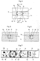
- the in 4, 5 and 6 shown section of a first separation section of a second separation device shows a U-shaped web 54 and arranged obliquely to the transport direction webs 53 as microstructure elements, which in the first separation section 5 of the first embodiment of a separation device according to the FIGS. 1 to 3 are similar.
- the first passages 16 are located between two webs 53 lying opposite each other, between a web 54 and the lateral boundary surface of the transport path 15 and between two adjacent webs 53, 53 or 54, 54 or 53, 54.
- the webs 53, 54 in FIG 4 to 6 differ from the respective webs 53, 54 according to the FIGS. 1 to 3 in that the webs in the region of the pockets 6a, 6b are provided with second passage openings 17.
- the second passage openings 17 have geometrical dimensions which allow only the at least individual smaller particles and / or the blood plasma contained in the blood to pass through while retaining complexes from the particles.
- the second passage openings 17 are smaller than the first passage openings 16.
- the first Through openings 16 allow both complexes of particles and individual particles and the blood plasma to pass through.
- the air escapes from the pockets in the direction of collection chamber 11, while liquid and particles or complexes of particles enter the pockets.
- Fig. 7 It is shown how blood plasma in the third separation device can be obtained from the blood by means of the method.
- Fig. 7 a part of the transport path 15, namely the incubation section 4 and the first separation section 5 shown.
- the blood plasma 12 is shown with a liquid front 12a, wherein in the blood plasma individual cells 13, cell clusters 14a or so-called Roulaus 14b float from blood cells.
- the cell clusters 14 a and Roulaus 14 b are formed in the incubation section under the influence of substances not supplied to the resuspension section.
- the capillary force acting along the transport path transports the blood from the incubation section 4 into the first separation section 5.
- Cell clusters 14a, Roulaus 14b or individual cells 13 accumulate in the pockets 6a and 6b of the microstructure elements 53 and 54. Through the second passage openings 17, the blood plasma 12 also flowing into the pockets 6a, 6b can emerge from the pockets in the transport direction.
- the first passage openings 16 between two adjacent microstructure elements 53 and 54 and between the microstructure elements 54 and the lateral boundary surfaces of the transport path 15 allow both passage of individual cells 13 and the passage of complexes, such as the cell cluster 14a or Roulaus 14b. Due to the complete or temporary retention of the complexes or individual cells formed by cell aggregates, an area is formed in the anterior flow front of the blood which essentially contains blood plasma and only a few cells.
- This mixture of blood plasma 12 and individual cells 13 is transported by the transport forces from the first separating section 5 into the second separating section 8, which is no longer shown.
- the microstructure elements a are webs or pillars having a substantially oval cross section, which extend from a lower boundary surface of the first separation section 5 to the top of a separation device.
- the microstructure elements b are columns which are staggered in three rows one behind the other.
- First through openings 16 are located between two adjacent microstructure elements a or between two adjacent microstructure elements b.
- the microstructure elements c are horseshoe-shaped webs, each defining first through openings 16 with adjacent horseshoe-shaped webs or with a lateral boundary surface of the first separating section 5.
- the webs may extend from the lower boundary surface to the upper part 1 b of a separating device, or between the top of the horseshoe-shaped webs and the upper part 1 b may remain a gap.
- the latter also applies to the microstructure elements a and b as well as the microstructure elements d, which are angled webs which extend in the first separation section counter to the transport direction. Between the ends of two adjacent angled webs is a first passage opening 16th
- the microstructure element e is a web which extends over the entire width of the transport path 15 from a first lateral boundary surface to a second lateral boundary surface. In this jetty are second Passages 17 included.
- a variant of the microstructure element e forms the microstructure element f, which is a single horseshoe-shaped web which, like the web f, contains second passage openings 17 and extends from a first lateral boundary surface to the second lateral boundary surface of the transport path.
- the microstructure elements g are webs which are arranged at an acute angle to the transport direction in order to arrest and / or slow down the complexes and to slow down individual particles, but to allow liquid components to pass through as undisturbed as possible.
- the fourth embodiment of a separation device has, in addition to the inlet 2 and the collecting section 11, a transport path 15 which has an incubation section 4, a first separation section 5, a second separation section 8 and a branch section 19 between the first separation section 5 and the second separation section 8.
- the transport path 15 bends off from the branching section 19 at a right angle, while the branching section 19 is followed by a second transporting path 18 which lies in a line with the incubation section 4 and the first separating section 5. From this second transport path 18 performs a vent channel 9 to the outside.
- a volume flow from the branch point toward the second transport path 18 and the second separation section 8 is present throughout the separation process.
- the liquid to be filtered flows parallel to the second separating section 8. A portion of the liquid is drawn off correspondingly transversely in the direction of the collecting section 11. Due to the continuous flow of the liquid to be separated at the branching portion 19 are particles with the Volume flow in the second transport path 18 washed away, and the occupancy of the surface of the second separation section 8 is reduced.
- the occupancy rate can be varied according to the volume flow. However, the volume flow is always laminar with Reynolds numbers less than 100. In embodiments in which the liquid is driven exclusively by capillary force, the volume flow over the channel dimensions and surface properties can be adjusted accordingly.
- the fifth separation device according to the fourth embodiment Fig. 9 is very similar, is in Fig. 10 shown.
- the branching section 19 is arranged in front of the first separating section.
- Both the first separation section 5 and the second separation section 8 are arranged parallel to the branching section 19 and parallel to the transport direction of the liquid from the branching section 19 to the second transporting path 18.
- the second transport path 18 is arranged in a linear extension to the incubation section 4.
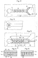
- the sixth embodiment of a separating device according to Fig. 11 is similar to the embodiment according to Fig. 1 , wherein, in contrast to the first embodiment according to Fig. 1 no Resuspensionsabêt 3 is provided in the transport path 15.
- the microstructure element of the second separation section 8 is a web (such as, for example, the microstructure element e or f in FIG Fig. 8 ) provided with perpendicular to the lower boundary surface slots. Behind this second separating section 8, the liquid constituents of the liquid accumulate in a collecting section 11. From the collecting section 11, a venting channel 9 is passed through a lower boundary surface of the collecting section 11.
- Fig. 12 is a section of a separator shown.
- the resuspension portion 3a is provided as a circular area on the lower boundary surface of the inlet 2.
- the liquid filled in the inlet 2 impinges directly on the substance of the resuspension section 3a, by which chemical or biochemical reactions between the substance and the particles in the liquid are triggered or accelerated in order to produce complexes with identical or different particles from the particles.
- FIGS. 13, 14 and 15 illustrated seventh embodiment of a separation device also has an inlet 2, a transport path 15 and a collecting portion, wherein the second separating portion and the collecting portion are not shown. It is in the Fig. 13 only the inlet and the first separation section 5 are shown.
- This first separation section 5 has a U-shaped web in plan view, which extends from the lower boundary surface of the first separation section 5 to the upper part 1 b of the separation device. This web separates two aerodynamically seen in the flow direction one behind the other lying areas of the separator from each other. A first region A is disposed between the legs of the web and directly connected to the inlet 2.
- the second area B is formed by a collecting channel, the U-shaped in plan view web on the Outside surrounds and is connected via a transport channel 22 with the second separating section, not shown.
- microstructural elements such as arranged obliquely to the transport direction webs 53, U-shaped webs 54 or columns 55 arranged to prevent or slow down the transport of complexes in the manner already described and the transport of individual particles slow it down.
- the U-shaped web has a passage opening 21 in its arc.
- the arc and the legs of the U-shaped web are slotted at regular intervals from the lower boundary surface of the first separating section 5 to the upper part 1 b of the separating device.
- the width of the slots 23 is dimensioned so that individual particles and liquid components of the liquid can pass.
- the slots 23 form second passage openings in the sense of the invention.
- the separator shown works as follows.
- the liquid is introduced into the inlet 2, from where it is transported by capillary force from the beginning to the end of the first region A of the first separation section 5.
- individual complexes and / or particles are stopped or slowed down by the microstructure elements 53, 54, 55 in the first region A.
- the liquid ingredients and individual particles enter the slots 23 in the U-shaped land. Since the transition from the slots 23 to the second region B of the liquid component separation section 5 constitutes a capillary stop, the liquid is initially not transported into the second region B via the slots 23.
- the passage opening 21 provided in the arch is not designed as a capillary stop, and the liquid entering this passage opening 21 can enter the second area B unhindered.
- the U-shaped web can be configured with its microstructure elements (slots) such that this U-shaped web already forms the second separating section of the separating device, and that the second region outside the U-shaped web serves as the collecting section of the separating device.
- the in the FIGS. 16 and 17 The device shown is similar to that in the FIGS. 13 to 15 illustrated device formed.
- the first separating section is completely enclosed by a web 103 and also includes this web 103.
- the web 103 is pierced by a multiplicity of slots 12 which form the first separating section with a parallel to the first separating section arranged as a collection area formed channel 102 connect.
- the slots 23 preferably have the same depth as the collecting channel 102.
- the slots form a capillary stop for the liquid in the transport direction from the first separating section in the direction of collection channel 102.
- the slots 23 have a depth of 1 .mu.m to 100 .mu.m, a width of 1 mm to 500 ⁇ m and a length of at least 50 ⁇ m.
- the passage opening 21 has the same depth as the collecting channel 102 and does not constitute a capillary stop for the incoming liquid.
- the separating section After adding the particle-containing liquid into the filling area, the separating section is completely filled by capillary action. Particles and complexes are in this case partially retained by the microstructure elements 53 and 54.
- the liquid flows into the collecting channel 102 and fills it in the direction of the inlet opening (see arrow 104).
- the cross section of the collecting channel 102 is smaller than the cross section of the collecting channel 100, whereby the liquid entering via the passage opening 21 preferably fills only the collecting region 102 and then continues to flow via the collecting channel 100.
- the individual slots 23 are wetted, whereby their Kapillarstoppfunktion is canceled, so that the present within the ridge 103 initially practically dormant liquid, can flow over the individual slots 23 in the direction of the collecting channel 100.
- particles or complexes are partially retained in the microstructures 54 now lying in the flow direction and by the slots 23, so that a substantially low-particle solution flows via the collecting region 102 in the direction of collecting channel 100, which leads to the second separating section (not shown).
- the in Fig. 18 shown sample carrier, as well as the other devices shown in the previous figures, suitable for carrying out a method.
- the sample carrier has, in addition to the inlet 2, only the first separating region 5 with microstructure elements and the collecting region 11.
Landscapes
- Chemical & Material Sciences (AREA)
- Health & Medical Sciences (AREA)
- General Health & Medical Sciences (AREA)
- Life Sciences & Earth Sciences (AREA)
- Analytical Chemistry (AREA)
- Dispersion Chemistry (AREA)
- Chemical Kinetics & Catalysis (AREA)
- General Physics & Mathematics (AREA)
- Biochemistry (AREA)
- Physics & Mathematics (AREA)
- Immunology (AREA)
- Pathology (AREA)
- Molecular Biology (AREA)
- Hematology (AREA)
- Clinical Laboratory Science (AREA)
- Investigating Or Analysing Biological Materials (AREA)
- Apparatus Associated With Microorganisms And Enzymes (AREA)
- Micro-Organisms Or Cultivation Processes Thereof (AREA)
Description
- Die vorliegende Erfindung betrifft eine mikrostrukturierte Trennvorrichtung zum Abtrennen von Teilen einer Flüssigkeit mit den Merkmalen des Oberbegriffs des Anspruchs 1, die flüssige Bestandteile und die zumindest einen Typ von Partikeln und/oder zumindest einen Komplex von miteinander verbundenen Partikeln zumindest eines Typs aufweist.
- Aus der Patentschrift zum Patent mit der Nummer 5,837,115 ist eine Vorrichtung bekannt, die einen Einlass für die Flüssigkeit, einen Sammelabschnitt und einen Transportweg von dem Einlass zu dem Sammelabschnitt umfasst. Der Transportweg seinerseits umfasst in Transportrichtung hintereinanderliegend einen ersten Trennabschnitt zum Zurückhalten zumindest eines Teils der Komplexe und/oder zum Verzögern der Bewegung zumindest eines Teils der Komplexe und/oder zumindest eines Teils der Partikel und einen zweiten Trennabschnitt zum Zurückhalten zumindest eines Teils der Komplexe und/oder zumindest eines Teils der Partikel und/oder zum Verzögern der Bewegung der Partikel. Sowohl der erste Trennabschnitt als auch der zweite Trennabschnitt weisen eine Mikrostruktur mit einem oder mehreren Mikrostrukturelementen auf.
- Aus den Dokumenten
US 2002/0196435 A1 ,WO 99/35497 A2 EP 1 450 159 A2 sind weitere Vorrichtungen mit Mikrostrukturen bekannt, die zum Abtrennen von Teilen einer Flüssigkeit benutzt werden können. - Die Dokumente
US 2002/0196435 A1 ,WO 99/35497 A2 EP 1 450 159 A2 offenbaren eine mikrostrukturierte Vorrichtung (siehe dortFig. 4 und 5 ) mit einem Einlassbereich und einem Resuspensionsbereich, in dem Agglutinationsreagenzien vorgelegt sind, einen Inkubationsbereich zwischen Resuspensionsbereich und darauf folgenden mehreren Trennbereichen, wobei der Inkubationsbereich derart ausgestaltet ist, dass die Strömungsgeschwindigkeit und die Aufenthaltsdauer derart sind, dass sich im Inkubationsbereich Komplexe bilden, die in den Trennbereichen verlangsamt oder zurückbehalten werden. Die Trennbereiche weisen mikrostrukturierte Elemente auf. - Die meisten klinisch-chemischen Untersuchungen werden an zellfreien Blutflüssigkeiten, Blutplasma oder Blutserum durchgeführt, da die Blutzellen oder ihre Inhaltsstoffe die Messergebnisse verfälschen können. Für diese Abtrennung werden bislang in der Hämatologie hauptsächlich Filtrations- und Zentrifugationstechniken eingesetzt. Die vollständige Abtrennung von Blutzellen, ohne dass ihre Membranen zerstört werden und sie ihren Inhalt in die Untersuchungslösung abgeben, erreicht man beispielsweise durch eine 15-minütige Zentrifugation bei 1500 Umdrehungen/Minute. Ein solches Verfahren ist aufwendig und zeitintensiv, weshalb entsprechend nach alternativen Systemen gesucht wird. Außerdem lassen sich kleinere Volumina im Bereich weniger Mikroliter mit den hier beschriebenen gängigen Verfahren nicht handhaben, was vor allem im Bereich Point-of-Care in der klinischen Diagnostik sowie in der pharmazeutischen Wirkstoffsuche von Bedeutung ist.
- Mit der Hilfe der Mikrosystemtechnik lassen sich dagegen extrem kleine Probenmengen handhaben. Zudem können viele Analysensystemkomponenten auf kleinstem Raum vereinigt werden. Medizinische Diagnostik lässt sich dadurch oftmals einfacher, kostengünstiger, patientenfreundlicher und vor allem patientennäher gestalten.
- Eine mikrostrukturierte Trennvorrichtung zum Abtrennen von Hämatokrit aus Vollblut ist neben der bereits genannten Patentschrift zum Patent mit der Nummer
US 5,837,115 beispielsweise aus der DruckschriftUS 6,319,719 B1 bekannt. Diese Druckschrift offenbart eine Trennvorrichtung, die einen Einlass aufweist, an den sich ein kapillarer Transportweg zu einem Reaktionsbereich anschließt. Entlang des Transportweges sind viele Hindernisse angeordnet. Zum Abtrennen des Hämatokrits aus einer Probe in der Größe eines Bluttropfens enthält der kapillare Transportweg etwa 105 Hindernisse. Jedes Hindernis hat eine konkave Form auf seiner stromabwärts gelegenen Seite in Bezug auf die Strömungsrichtung der Flüssigkeit. Im konkaven Bereich jedes Hindernisses liegt ein Volumen von 10-4 bis 10 -5 Mikroliter, in welchem Hämatokrit selektiv zurückgehalten wird. Das Volumen aller konkaven Bereiche entspricht etwa dem Volumen des abzutrennenden Hämatokrits. Der Abstand zwischen den Hindernissen ist einerseits groß genug, um keinen Filtereffekt zu erzeugen, andererseits ist der Abstand klein genug, um das im kapillaren Transportweg enthaltene Flüssigkeitsvolumen zu minimieren. Der kleinste Abstand zwischen zwei Hindernissen beträgt bevorzugt etwa 10 -5 Meter. Die Hindernisse sind bevorzugt hexagonal-dicht angeordnet. - Aufgabe der Erfindung ist es, eine Trennvorrichtung vorzuschlagen, mit welcher der Trennvorgang schnell durchgeführt werden kann. Eine weitere Aufgabe der Erfindung ist es, eine Trennvorrichtung vorzuschlagen, mit welcher flüssige und partikelförmige Bestandteile aus einer Flüssigkeit abgetrennt werden können, die bestimmte Partikel enthält. Es soll beispielsweise möglich sein, einen Teil des Blutplasmas und der weißen Blutkörperchen von dem übrigen Blut abzutrennen, wenn weiße Blutkörper und Blutplasma für bestimmte Analysezwecke allein benötigt werden. Weiter soll es beispielsweise möglich sein, im Blut enthaltene zelluläre Bestandteile, Bakterien oder Viren von den übrigen Partikeln im Blut zu trennen oder die an Blutplasma verarmte Flüssigkeit, in der die Partikel in angereicherter Form vorliegen, zu untersuchen.
- Die Aufgabe der Erfindung wird durch eine Trennvorrichtung gemäß Anspruch 1 gelöst.
- Die in den Dokumenten offenbarten Vorrichtungen offenbaren die im kennzeichnenden Teil des Anspruchs 1 angegebenen Merkmale nicht. Insbesondere weisen die dort offenbarten Vorrichtungen keine offenen Taschen auf. Ferner sind in dem ersten Trennabschnitt und dem zweiten Trennabschnitt keine ersten oder zweiten Durchtrittsöffnungen vorgesehen, die von Mikrostrukturelementen des ersten bzw. zweiten Trennabschnitts begrenzt werden und Abmessungen haben, wie sie bei einer erfindungsgemäßen Vorrichtung vorgesehen sind.
- Der Transportweg der erfindungsgemäßen Vorrichtung umfasst neben dem ersten Trennabschnitt zum Zurückhalten der Komplexe und/oder zum Verzögern der Bewegung der Komplexe und/oder von zumindest Teilen der Partikel und dem zweiten Trennabschnitt zum Zurückhalten der Komplexe und/oder von zumindest Teilen der Partikel und/oder zum Verzögern der Bewegung von zumindest Teilen der Partikel einen Resuspensionsabschnitt und einen Inkubationsabschnitt, die in Transportrichtung vor dem ersten Trennabschnitt angeordnet sind. Sowohl der erste Trennabschnitt als auch der zweite Trennabschnitt weisen eine Mikrostruktur mit einem oder mit mehreren Mikrostrukturelementen auf. Der in der erfindungsgemäßen Trennvorrichtung gemäß Anspruch 1 vorgesehene Inkubationsabschnitt dient dazu, der Flüssigkeit zugesetzten Substanzen die Möglichkeit zu geben, zur Bildung der Komplexe beizutragen, bevor die Flüssigkeit den ersten Trennabschnitt erreicht.
- In dem Resuspensionsabschnitt des Transportweges ist zumindest eine Substanz zur Herstellung der Komplexe aus den Partikeln und/oder zur Begünstigung der Herstellung der Komplexe aus den Partikeln angeordnet. Damit ist es unnötig, dass die Substanz vor einem Befüllen der Trennvorrichtung der Flüssigkeit hinzugegeben wird. Die Flüssigkeit wird vielmehr unmittelbar in die Trennvorrichtung eingefüllt, und nach Erreichen des Resuspensionsabschnitts nimmt die Flüssigkeit die in dem Resuspensionsabschnitt angeordnete Substanz oder, falls dort mehrere verschiedene Substanzen angeordnet sind, die Substanzen auf.
- Das Verhältnis der Oberfläche des Transportweges zum eingeschlossenen Volumen des Transportweges der mikrostrukturierten Trennvorrichtung ist im Gegensatz zu den Untersuchungsgefäßen, die man gewöhnlich in einem normalen Laboratorium antrifft, wesentlich vergrößert. Daraus resultieren u. a. folgende Abweichungen von den Verhältnissen in der Makrowelt.
- Oberflächeneffekte, Kapillar- und Adsorptionsphänomene spielen oft eine dominierende Rolle gegenüber Volumeneffekten. In Dimensionen unter 100 µm und Fließgeschwindigkeiten unter 100 cm/sec fließen Flüssigkeiten laminar d. h. als sogenannte Schichtströmung. Es treten keine Turbulenzen auf. Die Flüssigkeiten haben kleine Reynoldszahlen, typischerweise unterhalb Re = 100. Hierdurch ist die Durchmischung von Flüssigkeiten über Turbulenzen nicht gegeben. Andererseits stellt die Diffusion, aufgrund der geringen Abmessungen, einen schnellen und effizienten Mischmechanismus dar.
- Der Transportweg ist vorteilhaft so ausgestaltet, dass die Flüssigkeit durch Kapillarkraft bewegt wird.
Daneben können zum Transport von Flüssigkeiten andere Antriebsmechanismen wie die elektroosmotische Kraft (EOF) ausgenutzt. Hierzu ist der Transportweg der Vorrichtung, durch den die Flüssigkeit transportiert werden soll, entsprechend ausgelegt. Dies gilt hinsichtlich seiner Querschnittsflächen,
Querschnittgestaltungen und Oberflächeneigenschaften. - Bei Partikeln im Sinne der Erfindung kann es sich zum Beispiel um Feststoffpartikel aus Materialien wie Glas, Kunststoffe, Harze, oder um Partikel biologischen Ursprungs wie prokaryontische und eukaryontische biologische Zellen, Zellverbände, Zellfragmente, Organellen, Makromoleküle wie Nukleinsäuren, Proteine, etc. oder eine Kombination von Feststoffpartikeln und Partikel biologischen Ursprungs wie z. B. mit Zellen beschichteten Glasträgern handeln.
- Komplexe im Sinne der Erfindung sind jede Ansammlung von mehreren miteinander verbundenen Partikeln in der Flüssigkeit. Es kann sich dabei um regelmäßig angeordnete Partikel oder um willkürlich miteinander verbundene Partikel handeln. Die Verbindung kann durch zwischen den Partikeln wirkende Kräfte hergestellt sein. Die Verbindung kann aber auch durch eine zusätzliche Substanz zur Verbindung einzelner Partikel hergestellt sein. Die Partikel eines Komplexes können gleichen oder verschiedenen Types sein.
- Die Komplexe können grundsätzlich durch natürlich ablaufende Vorgänge erzeugt werden. Erfindungsgemäß werden sie jedoch gebildet oder ihre Bildung beschleunigt durch das Versetzen der Flüssigkeit mit der Substanz oder mit mehreren Substanzen in dem Resuspensionsbereich.
- Die erfindungsgemäße Trennvorrichtung gemäß Anspruch 1 genügt den an sie gestellten Forderungen. Sie ermöglicht insbesondere ein deutlich schnelleres Ablaufen des Abtrennvorganges. Durch den ersten Trennabschnitt werden zunächst Komplexe und/oder z. B. größere Partikel aufgehalten oder ihre Bewegung wird so verzögert, dass die flüssigen Bestandteile und einzelne, nicht in Komplexen gebundene Partikel schnell in die zweite Trennvorrichtung eintreten können, in welcher die verbleibenden Partikel, die nicht im Sammelabschnitt gesammelt werden sollen, aufgehalten oder verzögert werden. In dem Sammelabschnitt sammeln sich letztendlich nur solche flüssigen Bestandteile und gegebenenfalls Teile der Partikel, die von der übrigen Flüssigkeit abgetrennt werden sollen. Da nach einem vollständigen Befüllen des Sammelbereichs keine weiteren flüssigen Bestandteile mit darin enthaltenen anderen Partikeln oder gar Komplexen in den vollständig befüllten Sammelbereich eintreten können, kann so ein schnelles und zuverlässiges Abtrennen erreicht werden. Bei einer erfindungsgemäßen Trennvorrichtung reichen im Gegensatz zu der aus dem Stand der Technik bekannten Trennvorrichtung eine geringe Anzahl von 5 bis 100 Mikrostrukturelementen für einen erfolgreichen Trennvorgang aus.
- Die erfindungsgemäße Trennvorrichtung weist in dem Transportweg den Inkubationsabschnitt auf, der in Transportrichtung vor dem ersten Trennabschnitt angeordnet ist. Eine Flüssigkeit, die in dem Resuspensionsabschnitt eine Substanz aufgenommen hat, wird in den Inkubationsabschnitt transportiert, den die Flüssigkeit mit einer solchen Geschwindigkeit durchströmt, dass während der Aufenthaltszeit der Flüssigkeit in dem Inkubationsabschnitt die Substanz die gewünschte Bildung der Komplexe hervorruft oder beschleunigt. Damit kann sichergestellt werden, dass die Komplexe beim Erreichen des ersten Trennabschnitts durch die Flüssigkeit ausgebildet oder überwiegend ausgebildet sind. Durch die Ausgestaltung des Inkubationsabschnitt (Querschnittsfläche, Länge, Oberflächeneigenschaften wie Rauhigkeit und Benetzbarkeit) ist die Strömungsgeschwindigkeit und damit auch die Aufenthaltsdauer der Flüssigkeit im Inkubationsabschnitt reproduzierbar eingestellt.
- Die Mikrostrukturelemente des ersten Trennabschnitts weisen in Richtung zum Einlass d. h., entgegen der Transportrichtung offene Taschen auf und/oder die Mikrostrukturelemente schließen zumindest zum Teil mit zu den Mikrostrukturefementen benachbarten Begrenzungsflächen des Transportweges in Richtung zum Einlass offene Taschen ein.
- Eine bevorzugte erfindungsgemäße Vorrichtung erlaubt die Auftrennung von Blut in Plasma und Hämatokrit ohne Zugeben von Substanzen unter Ausnutzung der dem Blut innewohnenden Eigenschaften Zellaggregate, d. h. Komplexe, auszubilden. Ein Beispiel für eine unter natürlichen Bedingungen (ohne Zugeben einer Chemikalie) auftretende Komplexbildung, ist die Erythrozyten-Aggregation, insbesondere die Rouleau-Bildung, bei langsam fließendem oder nicht zirkulierendem Blut. Dabei legen sich die etwa acht Tausendstel Millimeter (µm) großen roten Blutkörperchen (Erythrozyten) münzrollenartig, zum Teil verzweigt, mit den flachen Seiten aneinander und bilden lange Ketten. Diese können mit normalen Mikroskopietechniken (Dunkelfeld- oder Phasenkontrastbeleuchtung) ohne großen Aufwand unter einem Lichtmikroskop mit angeschlossener Videokamera gezeigt werden. Die Strukturen der Vorrichtung sind so ausgelegt, dass die Fließgeschwindigkeiten und damit die Scherkräfte so gering sind, dass diese Rouleau-Bildung auftreten kann.
- Gemäß der Erfindung kann es sich bei den Mikrostrukturelementen des ersten Trennabschnitts zumindest teilweise um Säulen oder Stelen handeln, die einen kreisförmigen, hexagonalen, quadratischen, rechteckigen oder ovalen Querschnitt haben können. Ferner können die Mikrostrukturelemente zumindest teilweise einen oder mehrere Stege umfassen. Der bzw. die Stege können quer oder schräg zur Transportrichtung angeordnet sein. Die Stege können ferner U-förmig oder V-förmig gebogen bzw. abgewinkelt sein, so dass sie entgegen der Transportrichtung offenen Taschen haben.
- Die Mikrostrukturelemente des ersten Trennabschnitts begrenzen einen oder mehrere erste Durchtrittsöffnungen, die geometrische Abmessungen haben, die es einem Teil der Partikel und zumindest kleineren Komplexen sowie den flüssigen Bestandteilen der Flüssigkeit erlauben hindurchzutreten. Die so ausgebildeten ersten Durchtrittsöffnungen ermöglichen zwar das Hindurchtreten des Teils der Partikel und/oder zumindest der kleineren Komplexe, verlangsamen jedoch den Transport der Partikel und/oder Komplexe, da diese vorübergehend an den Mikrostrukturen aufgehalten werden oder zum Teil erst nach einer Deformation, so zum Beispiel bei roten Blutzellen, durch die ersten Durchtrittsöffnungen hindurchtreten können. Flüssige Bestandteile können die ersten Durchtrittsöffnungen ungehindert passieren. Durch eine Kollision mehrerer solcher Komplexe kann es innerhalb einer der ersten Durchtrittsöffnung zur Bildung von größeren Komplexen kommen.
- Die Mikrostrukturelemente des ersten Trennabschnitts begrenzen ferner zweite Durchtrittsöffnungen, die geometrische Abmessungen haben, die es nur den Partikeln oder bestimmten Typen von Partikeln sowie den flüssigen Bestandteilen der Flüssigkeit erlauben hindurchzutreten. Durch diese so ausgebildeten zweiten Durchtrittsöffnungen werden Komplexe zurückgehalten, während die Partikel oder die bestimmten Typen von Partikeln verlangsamt oder erst nach einer Deformation, die den Transport dieser Partikel auch verlangsamt, passieren können. Flüssige Bestandteile können diese ersten und/oder zweiten Durchtrittsöffnungen ungehindert passieren. Die zweiten Durchtrittsöffnungen können zum Teil in oder auf den Taschen der Mikrostrukturelemente des ersten Trennabschnitts beginnend vorgesehen sein. Dadurch wird es möglich, dass zwar ein Teil der Komplexe in den Taschen gesammelt und an einem Weitertransport gehindert wird, dass jedoch einzelne Partikel oder ein Teil der Komplexe und die flüssigen Bestandteile durch die zweiten Durchtrittsöffnungen weiter in Transportrichtung strömen können. Gemäß der Erfindung haben die ersten Durchtrittsöffnungen eine Breite und/oder eine Höhe von 1 µm bis 500 µm. Die Durchtrittsfläche der ersten Durchtrittsöffnungen kann in Transportrichtung abnehmen.
- Die Breite der zweiten Durchtrittsöffnungen kann gemäß der Erfindung 1 µm bis 500 µm betragen, während die Höhe von 0,1 µm bis 100 µm betragen kann. Die Durchtrittsfläche der zweiten Durchtrittsöffnungen kann ebenso wie die Durchtrittsfläche der ersten Durchtrittsöffnungen in Transportrichtung abnehmen.
- Eine Möglichkeit der Anbringung der Substanzen in dem Resuspensionsabschnitt einer erfindungsgemäßen Vorrichtung ist, dass die Substanzen oder die Substanz auf zumindest einer Begrenzungsfläche des Resuspensionsabschnitts eingetrocknet anhaftet. Eine weitere Möglichkeit ist, dass zumindest eine der Substanzen in Form eines Pellets, einer Tablette oder eines Pulvers im Resuspensionsabschnitt angeordnet ist. Ebenso ist es möglich, dass zumindest eine der Substanzen auf einem Träger aufgebracht ist, wobei der Träger im Resuspensionsabschnitt angeordnet ist. Die Substanz oder der Träger können dabei in einer Ausnehmung in einer der Begrenzungsflächen des Resuspensionsabschnitts angebracht sein.
- Die Partikel können zumindest zum Teil biologischen Ursprungs, zum Beispiel Zellen oder deren Organellen, Viren oder ähnliches sein. Das Entstehen von Komplexen aus Partikeln wird mittels einer oder mehrerer Substanze, durch eine Aggregation, Agglutination oder Koagulation, etc. erzeugt, begünstigt oder beschleunigt.
- Unter Aggregation versteht man in der Hämatologie die reversible Zusammenballung der roten Blutkörperchen durch relative (Flüssigkeitsverlust) oder absolute Zunahme vor allem größerer Eiweißkörperchen des Blutes (Agglomerine, z. B. Fibrinogen, Haptoglobin). Unter Agglutination versteht man die zumeist irreversible Verklebung antigentragender Teilchen (Erythrozyten, Bakterien bzw. bei passiver indirekter Agglutination von Latex-, Polystyrolpartikeln) durch entsprechende Agglutinine wie Antikörper oder Lektine. Die Antigen-Antikörper-Reaktion bewirkt eine Verklumpung partikulärer Antigene. Bei der direkten Agglutination sind die agglutinierenden Antikörper gegen Bakterien- oder zellgebundene Antigene gerichtet, bei der indirekten Agglutination werden lösliche Antigene an einen festen Träger gekoppelt. Die betreffenden Partikel sind meist groß genug, um mikroskopisch sichtbar zu sein.
- Zum Ausführen der Erfindung können als agglutinierende Substanzen auch agglutinierende Antikörper verwendet werden, die in der Probe befindliche antigentragende Partikel miteinander zu Komplexen verkleben (agglutinieren). Eine solche Reaktion kann zum Einen als Isolierungsverfahren verwendet werden, um bestimmte Partikel aus einer Partikel enthaltender Lösung zu entfernen, oder zum Anderen als Analysemethode zum Nachweis eines bestimmten Partikels in der Probenlösung. Hierzu kann der Trennabschnitt gleichzeitig als Detektionsbereich genutzt werden. Optisch schwer identifizierbare Partikel werden durch Zusammenlagerung zu Komplexen sichtbar gemacht und in dem Trennbereich angereichert (aufkonzentriert). Sie lassen sich so bequem und einfach über optische Verfahren, wie z. B. Streuungs- oder Trübungsmessungen oder lichtmikroskopische Verfahren, identifizieren.
- Diese zu den Substanzen im Sinne der Erfindung zählenden Antikörper können auch auf kugelförmige Träger aufgebracht werden. Diese kugelförmigen Träger sind häufig Polymer- oder Glaspartikel mit einem Durchmesser von 0,05 µm bis 100µm.
- Die Mikrostrukturelemente des zweiten Trennabschnitts können eine Treppe, voneinander beabstandete Säulen und/oder eine oder mehrere Stege umfassen, die mit einem Oberteil bzw. Deckel der Vorrichtung einen Spalt ausbilden oder ein oder mehrere Durchtrittsöffnungen schaffen. Grundsätzlich kann der zweite Trennabschnitt so ausgebildet sein, wie es beispielsweise für den Trennbereich einer in der deutschen Patentanmeldung mit dem Aktenzeichen
103 13 201.5/44 offenbarten Trennvorrichtung beschrieben ist. - Eine weitere Ausführung der erfindungsgemäßen Trennvorrichtung kann vor dem ersten Trennabschnitt oder zwischen dem ersten Trennabschnitt und dem zweiten Trennabschnitt einen Verzweigungsabschnitt aufweisen, von dem ausgehend ein zweiter Transportweg von dem ersten Transportweg abzweigt. Der Verzweigungsabschnitt und der von dem Verzweigungsabschnitt beginnende zweite Transportweg ermöglichen es, dass bei einem Verstopfen des ersten oder des zweiten Trennabschnitts durch Bildung eines so genannten "Filterkuchens" die nachströmende Flüssigkeit den ersten oder zweiten Trennabschnitt automatisch spült. Die sich vor dem Eingang oder im Eingangsbereich des ersten oder zweiten Trennabschnitts abgesetzten Partikel oder Komplexe werden durch die kontinuierlich nachströmende Flüssigkeit in den zweiten Transportweg abgeleitet. Dadurch ist erreicht, dass der erste oder zweite Trennabschnitt immer für den Abtrennvorgang freigehalten wird.
- Gemäß der Erfindung ist die Länge des ersten Transportweges bis zum zweiten Transportabschnitt so bemessen, dass auf Grund der eingeschränkten Mobilität der Komplexe die flüssigen Bestandteile oder flüssige Bestandteile und Partikel den zweiten Trennabschnitt zuerst erreichen. Vorteilhaft kann der Transportweg bezüglich Länge, Querschnitt, Oberflächenbeschaffenheit und Ausgestaltung der Mikrostrukturelemente so gestaltet sein, dass nur flüssige Bestandteile gegebenenfalls mit bestimmten Partikeln den Sammelbereich erreichen.
- Auf Grund der bevorzugt hydrophilen Eigenschaften von zumindest Teilen des Transportweges befüllen die mobileren flüssigen Bestandteile der Probe schneller den Sammelbereich als die Partikel oder Komplexe, die aufgrund ihrer Masse, Volumen und Größe, zum Teil oder vollständig im Trennbereich zurückgehalten werden.
- Das erfindungsgemäße Verfahren zum Abtrennen von Teilen einer Flüssigkeit ist in Anspruch 20 angegeben. Das Verfahren zum Abtrennen von Teilen einer Flüssigkeit die flüssige Bestandteile und zumindest einen Typ von Partikeln und/oder zumindest einen Komplex von miteinander verbundenen Partikeln zumindest eines Typs aufweist, weist folgende Schritte auf: Spätestens nach einer Inkubationszeit, während der sich zumindest einzelne Komplexe ausgebildet haben, wird die Flüssigkeit auf einen ersten Trennabschnitt einer Trennvorrichtung, beispielsweise einer erfindungsgemäßen Trennvorrichtung gegeben. In dem ersten Trennabschnitt werden die Komplexe zurückgehalten, und/oder die Bewegung der Komplexe und/oder von bestimmten Typen der Partikel oder aller Partikel wird verzögert.
- Die in dem Sammelbereich gesammelten abgetrennten Teile der Flüssigkeit können in dem Sammelabschnitt analysiert werden oder für eine weitere Analyse außerhalb der Trennvorrichtung dem Sammelbereich entnommen werden. Auch können die abgereicherten Partikel und/oder Komplexe in dem Trennabschnitt selbst oder in dem übrigen Teil der Transportwege analysiert werden.
- In einem zweiten Trennabschnitt der Trennvorrichtung können die Komplexe und/oder die Partikel zurückgehalten und/oder die Bewegung von bestimmten Typen der Partikel oder von allen Partikeln verzögert werden.
- Vor dem Beginn der Inkubationszeit kann zu der Flüssigkeit zumindest eine Substanz zugesetzt werden, die eine Herstellung und/oder eine Begünstigung der Herstellung von Komplexen von miteinander verbundenen Partikeln bewirkt. Die Flüssigkeit kann in einem Inkubationsabschnitt der Trennvorrichtung inkubiert werden. Ferner ist es möglich, dass die Substanz in einem Resuspensionsabschnitt der Trennvorrichtung der Flüssigkeit zugegeben und von der Flüssigkeit resuspendiert wird.
- Die Komplexe können zumindest zum Teil durch Agglomeration, Agglutination und/oder Koagulation der Partikel gebildet werden. Die Substanz, welche der Flüssigkeit zugesetzt werden kann, können mit Antikörpern oder Lektinen beschichtete Träger (Teile) enthalten, welche durch eine z. B. Antigen-Antikörper-Reaktion mit Oberflächenantigenen der Partikel die Bildung von Agglutinaten (Komplexen) bewirken.
- Die Beweglichkeit der Komplexe und/oder der Partikel kann durch die Mikrostrukturelemente in dem ersten Trennabschnitt zumindest zum Teil eingeschränkt werden, und die Komplexe können zumindest zum Teil durch die Mikrostrukturelemente des ersten Trennabschnitts zurückgehalten werden.
- Gemäß der Erfindung können die Komplexe durch die Mikrostrukturelemente der zweiten Trennvorrichtung zurückgehalten und/oder die Partikel zum Teil durch diese Mikrostrukturelemente zurückgehalten werden und/oder die Bewegung zumindest eines Teils der Partikel kann durch diese Mikrostrukturelemente verzögert werden.
- Gemäß der Erfindung kann die Flüssigkeit bzw. die abgetrennten Teile der Flüssigkeit durch Kapillarkraft und/oder eine andere in der Größenordnung vergleichbare Kraft transportiert werden.
- Gemäß der Erfindung kann die Vorrichtung einen Probenträger umfassen, in welchem der Einlass, der Transportweg und der Sammelabschnitt eingeformt sind, wobei die Vorrichtung ein Oberteil oder einen Deckel umfassen kann, der vorteilhaft den Transportweg und den Sammelabschnitt, d. h. die mikrostrukturierte Seite des Probenträgers mit Ausnahme des Einlasses abgedeckt. Die strukturierte Seite des Probenträgers kann zumindest teilweise hydrophilisiert sein, wenn die Vorrichtung für Proben mit hydrophilen Eigenschaften, z. B. wässrige Proben oder Blut vorgesehen ist.
- Die erfindungsgemäßen Verfahren können auch auf andere komplexbildende Flüssigkeiten als Blut angewendet werden. So können bestimmte Partikel in einer Flüssigkeit komplexiert und angereichert (aufkonzentriert) und nachgewiesen werden. Hierzu können auch die in den Trennbereichen angereicherten Komplexe z.B. für Analysezwecke von Interesse sein.
- Gemäß der Erfindung können als agglutinierende Substanzen auch agglutinierende Antikörper verwendet werden, die in der Flüssigkeit befindlichen antigentragende Partikel miteinander zu Komplexen verkleben (agglutinieren). Eine solche Reaktion kann zum einen als Isolierungsverfahren verwendet werden um bestimmte Partikel aus einer Partikel enthaltender Lösung zu entfernen, oder zum anderen als Analysemethode zum Nachweis eines bestimmten Partikels in der Probenlösung. Hierzu wird der Trennbereich gleichzeitig auch als Detektionsbereich genutzt. Optisch schwer identifizierbare Partikel werden durch Zusammenlagerung zu Komplexen sichtbar gemacht, in den Trennbereich angereichert (aufkonzentriert) und lassen sich so bequem und einfach über optische Verfahren, identifizieren.
- Diese Substanzen können auch auf kugelförmigen Träger aufgebracht werden. Diese kugelförmigen Träger sind häufig Polymer- oder Glaspartikel mit einem Durchmesser von 0,005 µm bis 100 µm.
- Ausführungsbeispiele für Trennvorrichtungen sind anhand der Zeichnung näher beschrieben. Darin zeigt
- Fig. 1
- eine Draufsicht auf das Unterteil einer ersten n Trennvorrichtung,
- Fig. 2
- einen Schnitt entsprechend der Linie II-II in
Fig. 1 durch die erste Trennvorrichtung, - Fig. 3
- einen Schnitt durch die erste Trennvorrichtung entsprechend der Linie III-III in
Fig. 1 , - Fig. 4
- eine Draufsicht auf einen Teil eines Unterteils einer zweiten, erfindungsgemäßen Trennvorrichtung,
- Fig. 5
- einen Schnitt durch die zweite Trennvorrichtung entsprechend der Linie V-V in
Fig. 4 , - Fig. 6
- einen Schnitt durch die zweite Trennvorrichtung entsprechend der Linie VI-VI in
Fig. 4 , - Fig. 7
- einen Teil einer dritten, erfindungsgemäßen Trennvorrichtung während eines Trennvorganges,
- Fig. 8
- verschiedene Beispiele für Mikrostrukturelemente in einem ersten Trennabschnitt einer Trennvorrichtung,
- Fig. 9 bis 11
- ein Unterteil eines vierten, fünften bzw. sechsten Ausführungsbeispiels einer Trennvorrichtung in Draufsicht,
- Fig. 12
- eine Variante für die Ausgestaltung eines Einlasses einer der Trennvorrichtungen,
- Fig. 13
- eine Draufsicht auf das Unterteil eines siebten Ausführungsbeispiels einer Trennvorrichtung,
- Fig. 14
- einen Schnitt entsprechend der Linie XIV-XIV durch das siebte Ausführungsbeispiel,
- Fig. 15
- einen Schnitt durch das siebte Ausführungsbeispiel gemäß der Linie XV-XV in
Fig. 14 , - Fig. 16
- eine Draufsicht auf den Probenträger eines achten Ausführungsbeispiels,
- Fig. 17
- einen Schnitt durch das achte Ausführungsbeispiels gemäß der Linie XVII-XVII in
Fig. 16 und - Fig. 18
- eine Draufsicht auf das Unterteil bzw. den Probenträger einer einfachen Vorrichtung zur Durchführung des Verfahrens.
- Die in den Figuren dargestellten Ausführungsbeispiele für Trennvorrichtungen weisen zum Teil gleiche und zum Teil entsprechende Merkmale auf, die mit gleichen Bezugszeichen gekennzeichnet sind.
- Das in den
Figuren 1 bis 3 dargestellte erste Ausführungsbeispiel weist ein Unterteil 1 a auf, in welchem ein Einlass 2 mit kreisförmiger Querschnittsfläche eingeformt ist. Von diesem Einlass 2 zweigt seitlich ein erster Transportweg 15 ab, der sich bis zu einem Sammelabschnitt 11 erstreckt. Der Sammelabschnitt 11 ist über einen Entlüftungskanal 9 mit der Umgebung verbunden. Ein Kapillarstopp in dem Transportkanal 9 kann das Austreten der in dem Sammelabschnitt 11 gesammelten flüssigen Bestandteile verhindern. - Ein solcher Kapillarstopp kann durch sich sprunghaft ändernde geometrische Abmessungen des Transportkanals 9 verwirklicht sein. Ebenso können sich Oberflächeneigenschaften des Transportkanals 9 sprunghaft ändern, beispielsweise von hydrophilen zu hydrophoben Oberflächen.
- Der Transportweg 15 zwischen dem Einlass 2 und dem Sammelabschnitt 11 ist in verschiedene Abschnitte unterteilt. In der Transportrichtung der Flüssigkeit, dass heißt in Richtung vom Einlass 2 zum Sammelabschnitt 11, sind hintereinander liegend ein Resuspensionsabschnitt 3, ein Inkubationsabschnitt 4, ein erster Trennabschnitt 5 und ein zweiter Trennabschnitt 8 angeordnet. Sowohl der erste Trennabschnitt 5 als auch der zweite Trennabschnitt 8 weisen dabei eine Mikrostruktur mit Mikrostrukturelementen 53, 54 ersten Trennabschnitt 5 bzw. Mikrostrukturelemente 83 im zweiten Trennabschnitt 8 auf.
- Neben dem Unterteil 1 a, bei dem es sich um einen Probenträger handeln kann, weist die in den
Figuren 1 bis 3 ausschnittsweise dargestellte erste Trennvorrichtung einen Deckel 1 b auf, der den Transportweg 15, den Sammelabschnitt 11 und den Entlüftungskanal 9 abdeckt und lediglich den Einlass 2 freilässt. - Die in den
Figuren 1 bis 3 dargestellte erste Trennvorrichtung ist dazu geeignet, aus Blut Blutplasma zu gewinnen, wobei das Hämatokrit beim Transport entlang des Transportweges 15 in dem ersten Trennabschnitt 5 und dem zweiten Trennabschnitt 8 des Transportwegs 15 verbleibt, so dass sich nur Blutplasma in dem Sammelabschnitt 11 sammelt. - Das Hämatokrit wird von dem Blutplasma unter anderem wegen der beim Transport des Bluts entlang des Transportweges 15 auftretenden Oberflächeneffekte getrennt.
- Die Partikel enthaltende Flüssigkeit wird im ersten Trennabschnitt 5 nach dem folgenden Prinzip getrennt: Die Mobilität von Partikeln und Komplexen wird im Vergleich zu der übrigen Flüssigkeit so eingeschränkt, dass sie langsamer durch eine Kapillare transportiert werden als die übrige Bestandteile der Flüssigkeit. Durch die Bildung der Komplexe (was eine Erhöhung der Masse, des Volumens, und der Größe bewirkt) sind die in Komplexen gebundenen Partikel im Volumenstrom nochmals weniger mobil als die ungebundenen Partikel.
- Durch die im Trennabschnitt 5 eingebrachten, vorzugsweise quer zur Strömungsrichtung vorliegenden Mikrostrukturelemente 53, 54 wird die Bewegung bzw. die Geschwindigkeit der Komplexe im kontinuierlichen Durchfluss weiter beeinträchtigt. Die Trennung der so in Komplexen gebundenen Partikel von der übrigen Partikel enthaltenen Probenflüssigkeit beruht auf der erwähnten Änderung der Masse, des Volumens, der Ladung und der Größe.
- Aufgrund ihrer viskoelastischen Eigenschaften können Erythrozyten auch Spalten oder Kapillaren durchströmen, die kleiner sind als ihr Durchmesser oder ihre Dicke. Der Durchtritt eines Erythrozyten durch kapillare Spalten mit einer Spaltöffnung kleiner als 5 µm ist komplex und erfolgt verzögert durch eine Walzbewegung, die nicht nach Hagen-Poiseuille zu beschreiben ist. Die Spalthöhe zwischen dem Steg 83 des zweiten Trennabschnitts 8 und dem Oberteil der Vorrichtung ist, wenn Plasma aus Blut isoliert werden soll, bevorzugt kleiner als 5 µm, um einzelne ungebundene Blutkörperchen aus der Probenflüssigkeit in dem Trennabschnitt 8 zurückzuhalten. Während der Trennabschnitt 8 für das Plasma kein oder nur ein geringes Hindernis darstellt, werden die roten Blutkörperchen im Trennabschnitt aufgehalten bzw. abgebremst und können diesen nur langsam durchdringen. Hierbei ist die Eindringtiefe der roten Blutkörperchen abhängig von der Höhe des Spalts und der Zeit bis die Sammelkammer 11 vollständig mit Flüssigkeit befüllt ist. Die Länge des Trennabschnitts 8 in Fließrichtung ist so gewählt, dass die Sammelkammer 11 schon komplett mit dem mobileren Plasma befüllt ist, ehe die ersten einzelnen roten Blutkörperchen den Trennabschnitt 8 vollständig überwunden haben.
- Die Mikrostrukturelemente 53, 54 formen insbesondere im ersten Trennabschnitt 5 entgegen der Transportrichtung, dass heißt in Richtung des Einlasses 2 offene Taschen 6a, 6b. Die Mikrostrukturelemente 54 sind als in der Draufsicht U-förmige Stege ausgebildet, deren beiden Schenkel in Richtung des Einlasses 2 weisen. Zwischen den U-förmigen Schenkeln wird die Tasche 6a ausgebildet. Die Mikrostrukturelemente 53 des ersten Trennabschnitts 5 sind als schräg in Richtung zum Einlass weisende Stege 53 ausgebildet, welche an der seitlichen Begrenzungsfläche des Transportweges 15 angeschlossen sind. Der zwischen den Stegen 53 und der seitlichen Begrenzungsfläche des Transportweges 15 ausgebildete spitzwinklige Bereich formt die Tasche 6b dieser zweiten Mikrostrukturelemente 53. In den Taschen 6a, 6b der Mikrostrukturelemente 54, 53 sammeln sich Komplexe und Partikel des Bluts (Hämatokrit), deren Transport entlang des Transportweges dadurch unterbunden oder zumindest verzögert wird, während kleinere Partikel des Blutes allenfalls verzögert den ersten Trennabschnitt 5 passieren können. Diese kleineren Partikel werden jedoch in dem zweiten Trennabschnitt 8 zurückgehalten, bei dem ein Steg 83 ein Zurückhalten oder zumindest ein Verzögern der Bewegung der kleineren Partikel des Hämatokrits bewirkt. Größere Partikel die zwar verzögert aber dennoch den ersten Trennabschnitt 5 des Transportweges 15 passieren, werden in jedem Fall von dem Mikrostrukturelement des zweiten Trennabschnitts 8 zurückgehalten.
- Der Transportweg 15 vor dem ersten Trennabschnitt umfasst den Inkubationsabschnitt 4. In diesem Abschnitt oder in Inkubationsabschnitten 4 eines der anderen Ausführungsbeispiele für Trennvorrichtungen können Substanzen, die zuvor dem Blut oder einer anderen zu behandelnden Flüssigkeit zugegeben wurden, auf die Flüssigkeit einwirken. Diese Substanzen sind so ausgewählt, dass sie die Bildung von Komplexen aus in der Flüssigkeit enthaltenen Partikel, zum Beispiel die Bildung von Komplexen aus roten Blutzellen hervorrufen oder zumindest beschleunigen. Insbesondere bei Blut können diese Komplexe durch Aggregation, Agglutination oder Koagulation von roten und/oder weißen Blutzellen oder anderen im Blut enthaltenen Zellen oder Viren erzeugt werden.
- Die Substanzen oder die Substanz, welche die Bildung der Komplexe hervorruft oder begünstigt, wird in einem Resuspensionsbereich 3 der ersten Trennvorrichtung aufgenommen. Während die Flüssigkeit den Inkubationsabschnitt 4 in Transportrichtung durchströmt, wirkt die Substanz auf die Flüssigkeit ein, so dass die Komplexe ausgebildet werden oder im Wesentlichen ausgebildet sind, wenn die Flüssigkeit den ersten Trennabschnitt 5 erreicht. Die Komplexe der Partikel bzw. Blutzellen werden durch die Mikrostrukturelemente 53, 54 zum Teil aufgehalten und zum Teil verlangsamt. Die Komplexe, die aufgehalten werden, werden z. B. in den Taschen 6a, 6b der Mikrostrukturelemente gesammelt. Vorzugsweise entspricht das Gesamtvolumen aller Taschen dem Volumen der in der Flüssigkeit enthaltenen Partikel, dass heißt des Hämatokrits. Am Ende des ersten Trennabschnitts 5 gelangt eine Flüssigkeit an, die im Wesentlichen nur noch einzelne Partikel bzw. Blutzellen enthält, die nicht in Komplexen gebunden sind. Diese letzten Partikel bzw. Blutzellen werden im zweiten Trennabschnitt 8 durch den dort angeordneten Steg 83 aufgehalten oder verlangsamt, so dass im Sammelabschnitt ausschließlich Blutplasma ohne zelluläre Bestandteile oder ähnlichem anlangt, bis der Sammelabschnitt vollständig befüllt ist.
- Die im Resuspensionsabschnitt 3 angeordnete Substanz 3a kann in Tablettenform auf der unteren Begrenzungsfläche des Transportweges 15 bzw. des Resuspensionsabschnitts 3 angebracht sein.
- Der in
Fig. 4, 5 und 6 dargestellte Ausschnitt aus einem ersten Trennabschnitt einer zweiten Trennvorrichtung zeigt einen U-förmigen Steg 54 und schräg zur Transportrichtung angeordnete Stege 53 als Mikrostrukturelemente, die den in dem ersten Trennabschnitt 5 des ersten Ausführungsbeispiels für eine Trennvorrichtung gemäß derFiguren 1 bis 3 ähnlich sind. Zwischen zwei einander gegenüberliegenden Stegen 53, zwischen einem Steg 54 und der seitlichen Begrenzungsfläche des Transportweges 15 sowie zwischen zwei benachbarten Stegen 53, 53 oder 54, 54 oder 53, 54 befinden sich die ersten Durchtrittsöffnungen 16. Die Stege 53, 54 gemäßFig. 4 bis 6 unterscheiden sich von den entsprechenden Stegen 53, 54 gemäß derFiguren 1 bis 3 dadurch, dass die Stege im Bereich der Taschen 6a, 6b mit zweiten Durchtrittsöffnungen 17 versehen sind. Die zweiten Durchtrittsöffnungen 17 haben geometrische Abmessungen, die es nur den im Blut enthaltenen zumindest einzelnen kleineren Partikeln und/oder dem Blutplasma erlauben hindurchzutreten, während Komplexe aus den Partikeln zurückgehalten werden. Die zweiten Durchtrittsöffnungen 17 sind kleiner als die ersten Durchtrittsöffnungen 16. Die ersten Durchtrittsöffnungen 16 erlauben sowohl Komplexen aus Partikeln als auch einzelnen Partikeln sowie dem Blutplasma das Hindurchtreten. Durch die zweiten Durchtrittsöffnungen 17 entweicht die Luft aus den Taschen in Richtung Sammelkammer 11, während Flüssigkeit und Partikel oder Komplexe aus Partikeln in die Taschen eintreten. - In
Fig. 7 ist dargestellt, wie Blutplasma in der dritten Trennvorrichtung mit Hilfe des Verfahrens aus Blut gewonnen werden kann. Dazu ist inFig. 7 ein Teil des Transportweges 15, nämlich der Inkubationsabschnitt 4 und der erste Trennabschnitt 5 dargestellt. Ferner ist das Blutplasma 12 mit einer Flüssigkeitsfront 12a dargestellt, wobei in dem Blutplasma einzelne Zellen 13, Zellhaufen 14a oder sogenannte Roulaus 14b aus Blutzellen schwimmen. Die Zellhaufen 14a und Roulaus 14b bilden sich im Inkubationsabschnitt unter Einfluss von im nicht dargestellten Resuspensionsabschnitt zugeführten Substanzen aus. Durch die entlang des Transportweges wirkende Kapillarkraft wird das Blut aus dem Inkubationsabschnitt 4 in den ersten Trennabschnitt 5 transportiert. Dabei sammeln sich Zellhaufen 14a, Roulaus 14b oder einzelne Zellen 13 in den Taschen 6a und 6b der Mikrostrukturelemente 53 und 54. Durch die zweiten Durchtrittsöffnungen 17 kann das ebenfalls in die Taschen 6a, 6b fließende Blutplasma 12 aus den Taschen in Transportrichtung wieder heraustreten. Die ersten Durchtrittsöffnungen 16 zwischen zwei benachbarten Mikrostrukturelementen 53 und 54 sowie zwischen den Mikrostrukturelementen 54 und den seitlichen Begrenzungsflächen des Transportweges 15 erlauben sowohl ein Hindurchtreten einzelner Zellen 13 als auch das Hindurchtreten von Komplexen, wie zum Beispiel den Zellhaufen 14a oder den Roulaus 14b. Durch das vollständige oder vorübergehende Zurückhalten der durch Zellaggregate gebildeten Komplexe oder einzelner Zellen bildet sich in der vorderen Fließfront des Bluts ein Bereich aus, der im Wesentlichen Blutplasma und nur noch vereinzelt Zellen enthält. - Diese Mischung aus Blutplasma 12 und einzelnen Zellen 13 wird durch die Transportkräfte aus dem ersten Trennabschnitt 5 in den nicht mehr dargestellten zweiten Trennabschnitt 8 transportiert.
- Die in
Fig. 8 dargestellten Varianten für Mikrostrukturelemente im ersten Trennabschnitt können allein oder in verschiedensten Kombinationen in einem ersten Trennbereich angeordnet sein. Bei den Mikrostrukturelementen a handelt es sich um Stege oder Säulen mit im Wesentlichen ovalen Querschnitt, die sich von einer unteren Begrenzungsfläche des ersten Trennabschnitts 5 bis zu dem Oberteil einer Trennvorrichtung erstrecken. Die Mikrostrukturelemente b sind Säulen, die in drei Reihen hintereinander gestaffelt stehen. Zwischen zwei benachbarten Mikrostrukturelementen a oder zwischen zwei benachbarten Mikrostrukturelementen b befinden sich erste Durchtrittsöffnungen 16. Die Mikrostrukturelemente c sind hufeisenförmig ausgebildete Stege, die jeweils erste Durchtrittsöffnungen 16 mit benachbarten hufeisenförmigen Stegen oder mit einer seitlichen Begrenzungsfläche des ersten Trennabschnitts 5 begrenzen. Die Stege können sich von der unteren Begrenzungsfläche bis zum Oberteil 1 b einer Trennvorrichtung erstrecken, oder zwischen der Oberseite der hufeisenförmigen Stege und dem Oberteil 1 b kann ein Spalt verbleiben. Letzteres gilt auch für die Mikrostrukturelemente a und b sowie die Mikrostrukturelemente d, bei den es sich um abgewinkelte Stege handelt, die sich entgegen der Transportrichtung in dem ersten Trennabschnitt erstrecken. Zwischen den Enden zwei benachbarter abgewinkelter Stege befindet sich eine erste Durchtrittsöffnung 16. - Bei dem Mikrostrukturelement e handelt es sich um einen Steg, der sich über die gesamte Breite des Transportweges 15 von einer ersten seitlichen Begrenzungsfläche zu einer zweiten seitlichen Begrenzungsfläche erstreckt. In diesem Steg sind zweite Durchtrittsöffnungen 17 enthalten. Eine Variante zu dem Mikrostrukturelement e bildet das Mikrostrukturelement f, bei dem es sich um einen einzelnen hufeisenförmigen Steg handelt, der wie der Steg f zweite Durchtrittsöffnungen 17 enthält und sich von einer ersten seitlichen Begrenzungsfläche zur zweiten seitlichen Begrenzungsfläche des Transportweges erstreckt. Bei den Mikrostrukturelementen g handelt es sich um Stege, die in einem spitzen Winkel zur Transportrichtung angeordnet sind, um die Komplexe aufzuhalten und/oder zu verlangsamen sowie einzelne Partikel zu verlangsamen, jedoch flüssige Bestandteile möglichst ungestört passieren zu lassen.
- Das vierte Ausführungsbeispiel einer Trennvorrichtung gemäß
Fig. 9 weist neben dem Einlass 2 und dem Sammelabschnitt 11 einen Transportweg 15 auf, der einen Inkubationsabschnitt 4, einen ersten Trennabschnitt 5, einen zweiten Trennabschnitt 8 und zwischen dem ersten Trennabschnitt 5 und dem zweiten Trennabschnitt 8 einen Verzweigungsabschnitt 19 aufweist. Der Transportweg 15 knickt ab dem Verzweigungsabschnitt 19 in einem rechten Winkel ab, während sich an den Verzweigungsabschnitt 19 ein zweiter Transportweg 18 anschließt, welcher in einer Linie mit dem Inkubationsabschnitt 4 und dem ersten Trennabschnitt 5 liegt. Von diesem zweiten Transportweg 18 führt ein Entlüftungskanal 9 nach außen. - Im Unterschied zu den vorherigen Beispielen ist während des gesamten Trennvorgangs ein Volumenstrom vom Verzweigungspunkt in Richtung zum zweiten Transportweg 18 und zum zweiten Trennabschnitt 8 hin vorhanden. Die zu filtrierende Flüssigkeit fließt parallel zum zweiten Trennabschnitt 8. Ein Teil der Flüssigkeit wird entsprechend quer in Richtung zum Sammelabschnitt 11 abgezogen. Aufgrund der kontinuierlichen Strömung der zu trennenden Flüssigkeit an dem Verzweigungsabschnitt 19 werden Partikel mit dem Volumenstrom in den zweiten Transportweg 18 fortgespült, und die Belegung der Oberfläche des zweiten Trennabschnitts 8 wird verringert. Der Belegungsgrad lässt sich in Abhängigkeit vom Volumenstrom entsprechend variieren. Der Volumenstrom ist jedoch immer laminar mit Reynolds-Zahlen kleiner als 100. In Ausführungsbeispielen, bei denen die Flüssigkeit ausschließlich durch Kapillarkraft getrieben wird, lässt sich der Volumenstrom über die Kanaldimensionen und Oberflächeneigenschaften entsprechend einstellen.
- Die fünfte Trennvorrichtung, die dem vierten Ausführungsbeispiel gemäß
Fig. 9 sehr ähnlich ist, ist inFig. 10 dargestellt. Bei dem fünften Ausführungsbeispiel gemäßFig. 10 ist jedoch anders als bei dem vierten Ausführungsbeispiel gemäßFig. 9 der Verzweigungsabschnitt 19 vor dem ersten Trennabschnitt angeordnet. Sowohl der erste Trennabschnitt 5 als auch der zweite Trennabschnitt 8 sind parallel zum Verzweigungsabschnitt 19 und parallel zur Transportrichtung der Flüssigkeit vom Verzweigungsabschnitt 19 zum zweiten Transportweg 18 angeordnet. Der zweite Transportweg 18 ist in linearer Verlängerung zum Inkubationsabschnitt 4 angeordnet. Durch die Anordnung des ersten Trennabschnitts 5 parallel zum Verzweigungsabschnitt 19 wird der Eingangsbereich des ersten Trennabschnitts 5 automatisch gespült. Der Eingangsbereich des ersten Trennabschnitts 5 wird nicht durch einen dort gebildeten "Filterkuchen" verstopft. Ein ständiger Volumenstrom in dem ersten Transportweg 15 und dem zweiten Transportweg 18 bis zum Abschluss der Befüllung des Sammelabschnitts 11 wird erreicht. - Das sechste Ausführungsbeispiel einer Trennvorrichtung gemäß
Fig. 11 ähnelt dem Ausführungsbeispiel gemäßFig. 1 , wobei im Unterschied zu dem ersten Ausführungsbeispiel gemäßFig. 1 kein Resuspensionsabschnitt 3 im Transportweg 15 vorgesehen ist. Als Mikrostrukturelement des zweiten Trennabschnitts 8 ist ein Steg (wie z. B. das Mikrostrukturelement e oder f inFig. 8 ) mit senkrecht zu der unteren Begrenzungsfläche stehenden Schlitzen vorgesehen. Hinter diesem zweiten Trennabschnitt 8 sammeln sich die flüssigen Bestandteile der Flüssigkeit in einem Sammelabschnitt 11. Von dem Sammelabschnitt 11 ist ein Entlüftungskanal 9 durch eine untere Begrenzungsfläche des Sammelabschnitts 11 hindurchgeführt. - In
Fig. 12 ist ein Ausschnitt aus einer Trennvorrichtung dargestellt. Im Einlass 2 ist der Resuspensionsabschnitt 3a als kreisförmige Fläche auf der unteren Begrenzungsfläche des Einlasses 2 vorgesehen. Die in den Einlass 2 gefüllte Flüssigkeit trifft unmittelbar auf die Substanz des Resuspensionsabschnittes 3a, durch die chemische oder biochemische Reaktionen zwischen der Substanz und den Partikeln in der Flüssigkeit ausgelöst oder beschleunigt werden, um aus den Partikeln Komplexe mit gleichartigen oder verschiedenen Partikeln zu erzeugen. - Das in
Fig. 13, 14 und 15 dargestellte siebte Ausführungsbeispiel einer Trennvorrichtung weist ebenfalls einen Einlass 2, einen Transportweg 15 und einen Sammelabschnitt auf, wobei der zweite Trennabschnitt und der Sammelabschnitt nicht dargestellt sind. Es sind in derFig. 13 lediglich der Einlass und der erste Trennabschnitt 5 dargestellt. Dieser erste Trennabschnitt 5 weist einen in Draufsicht U-förmigen Steg auf, der sich von der unteren Begrenzungsfläche des ersten Trennabschnitts 5 bis zu dem Oberteil 1 b der Trennvorrichtung erstreckt. Dieser Steg trennt zwei strömungstechnisch gesehen in Strömungsrichtung hintereinander liegende Bereiche der Trennvorrichtung voneinander ab. Ein erster Bereich A ist zwischen den Schenkeln des Steges angeordnet und mit dem Einlass 2 unmittelbar verbunden. Der zweite Bereich B wird durch einen Sammelkanal gebildet, der den in Draufsicht u-förmigen Steg auf der Außenseite umgibt und über einen Transportkanal 22 mit dem nicht dargestellten zweiten Trennabschnitt verbunden ist. In dem ersten Bereich des ersten Trennabschnitts 5 sind Mikrostrukturelemente wie zum Beispiel schräg zur Transportrichtung angeordnete Stege 53, u-förmige Stege 54 oder Säulen 55 angeordnet, die auf die bereits beschriebene Art und Weise den Transport von Komplexen verhindern oder verlangsamen und den Transport einzelner Partikel verlangsamen. Am in Strömungsrichtung liegenden Ende des ersten Bereiches A weist der U-förmige Steg in seinem Bogen eine Durchtrittsöffnung 21 auf. Der Bogen und die Schenkel des U-förmigen Steges sind in regelmäßigen Abständen von der unteren Begrenzungsfläche des ersten Trennabschnitts 5 zu dem Oberteil 1 b der Trennvorrichtung geschlitzt. Die Breite der Schlitze 23 ist dabei so bemessen, dass einzelne Partikel und flüssige Bestandteile der Flüssigkeit hindurchtreten können. Die Schlitze 23 bilden zweite Durchtrittsöffnungen im Sinne der Erfindung. - Die in
Fig. 13 bis 15 dargestellte Trennvorrichtung funktioniert folgendermaßen. Die Flüssigkeit wird in den Einlass 2 gegeben, von wo aus sie durch Kapillarkraft vom Anfang bis zum Ende des ersten Bereichs A des ersten Trennabschnitts 5 transportiert wird. Dabei werden einzelne Komplexe und/oder Partikel von den Mikrostrukturelementen 53, 54, 55 im ersten Bereich A aufgehalten oder verlangsamt. Die flüssigen Bestandteile und einzelne Partikel treten in die Schlitze 23 in dem U-förmigen Steg ein. Da der Übergang von den Schlitzen 23 zu dem zweiten Bereich B des Trennabschnitts 5 für die flüssigen Bestandteile einen Kapillarstopp darstellt, wird die Flüssigkeit über die Schlitze 23 zunächst nicht in den zweiten Bereich B transportiert. Die in dem Bogen vorgesehene Durchtrittsöffnung 21 ist nicht als Kapillarstopp ausgelegt, und die in diese Durchtrittsöffnung 21 eintretende Flüssigkeit kann ungehindert in den zweiten Bereich B eintreten. Dieses kann beispielsweise durch Kerben oder ähnliches erreicht werden. Sobald die flüssigen Bestandteile den ersten Bereich A vollständig befüllt haben und die Durchtrittsöffnung 21 im Bogen des U-förmigen Steges benetzt ist, tritt Flüssigkeit durch die Durchtrittsöffnung 21 in den zweiten Bereich B ein und befüllt diesen. Die Flüssigkeit benetzt dabei die Außenseite des U-förmigen Steges und die Schlitze 23, wodurch der Kapillarstopp auf der Außenseite des U-förmigen Steges aufgehoben wird. Die in den Schlitzen 23 anstehende Flüssigkeit kann aus den Schlitzen 23 austreten, und ein Transport der Flüssigkeit und der in ihr enthaltenen einzelnen Partikel aus dem ersten Bereich A in den zweiten Bereich B des ersten Trennabschnitts 5 beginnt. In dem zweiten Bereich B sammeln sich flüssige Bestandteile der Flüssigkeit mit einzelnen Partikel. Auf Grund der in dem zweiten Bereich B und dem Transportkanal 22 wirkenden Kapillarkraft wird diese Mischung aus flüssigen Bestandteilen und einzelnen Partikeln zu einem zweiten Trennabschnitt transportiert, in dem die einzelnen Partikel auf die zuvor schon mehrfach beschriebene Art und Weise aus der Flüssigkeit entfernt werden. - In einer alternativen Ausführung zu der Trennvorrichtung gemäß der
Figuren 13 bis 15 kann der U-förmige Steg mit seinen Mikrostrukturelementen (Schlitzen) so ausgestaltet sein, dass dieser U-förmige Steg bereits den zweiten Trennabschnitt der Trennvorrichtung bildet, und dass der zweite Bereich außerhalb des U-förmigen Steges als Sammelabschnitt der Trennvorrichtung dient. - Die in den
Figuren 16 und 17 dargestellte Vorrichtung ist ähnlich wie die in denFiguren 13 bis 15 dargestellte Vorrichtung ausgebildet. Der erste Trennabschnitt ist vollständig durch einen Steg 103 umschlossen und umfasst auch diesen Steg 103. Der Steg 103 ist durch eine Vielzahl von Schlitzen 12 durchbrochen, die den ersten Trennabschnitt mit einem parallel zum ersten Trennabschnitt angeordneten als Sammelbereich ausgebildeten Kanal 102 verbinden. Hierbei haben die Schlitze 23 bevorzugt dieselbe Tiefe wie der Sammelkanal 102. Die Schlitze bilden einen Kapillarstop für die Flüssigkeit in Transportrichtung vom ersten Trennabschnitt in Richtung Sammelkanal 102. Die Schlitze 23 haben eine Tiefe von 1 µm bis 100 µm, eine Breite von 1 mm bis 500 µm und eine Länge von mindestens 50 µm. Die Durchtrittsöffnung 21 hat dieselbe Tiefe wie der Sammelkanal 102 und stellt für die ankommende Flüssigkeit keinen Kapillarstop dar. - Nach Zugabe der Partikel enthaltenden Flüssigkeit in den Einfüllbereich wird durch Kapillarkraft der Trennabschnitt vollständig befüllt. Partikel und Komplexe werden hierbei teilweise von den Mikrostrukturelementen 53 und 54 zurückgehalten. Sobald die Flüssigkeit die Durchtrittsöffnung 21 befüllt hat, fließt die Flüssigkeit in den Sammelkanal 102 und befüllt diesen in Richtung der Einlassöffnung (siehe Pfeil 104). Der Querschnitt des Sammelkanals 102 ist kleiner als der Querschnitt des Sammelkanals 100, wodurch die über die Durchtrittsöffnung 21 eintretende Flüssigkeit bevorzugt erst den Sammelbereich 102 befüllt und dann erst über den Sammelkanal 100 weiterfließt. Während des Befüllvorgangs des Sammelbereichs 102 werden die einzelnen Schlitze 23 benetzt, wodurch deren Kapillarstoppfunktion aufgehoben wird, so dass die innerhalb des Steges 103 vorliegende zunächst praktisch ruhende Flüssigkeit, über die einzelnen Schlitze 23 in Richtung Sammelkanal 100 strömen kann. Hierbei werden Partikel oder Komplexe in den jetzt in Strömungsrichtung liegenden Mikrostrukturen 54 und durch die Schlitze 23 zum Teil zurückgehalten, so dass eine im Wesentlichen partikelarme Lösung über den Sammelbereich 102 in Richtung Sammelkanal 100 strömt, der zum zweiten Trennabschnitt (nicht dargestellt) führt.
- Der in
Fig. 18 dargestellte Probenträger ist, wie auch die übrigen in den vorherigen Figuren dargestellten Vorrichtungen, für die Durchführung eines Verfahrens geeignet. Der Probenträger weist dazu neben dem Einlass 2 lediglich den ersten Trennbereich 5 mit Mikrostrukturelementen und den Sammelbereich 11 auf.
Claims (37)
- Mikrostrukturierte Trennvorrichtung zum Abtrennen von Teilen einer Flüssigkeit, die flüssige Bestandteile und zumindest einen Typ von Partikeln und/oder zumindest einen Komplex von miteinander verbundenen Partikeln zumindest eines Typs aufweist, mit folgenden Merkmalen:- die Vorrichtung umfasst einen Einlass (2) für die Flüssigkeit, einen Sammelabschnitt (11) und einen Transportweg (15) von dem Einlass (2) zu dem Sammelabschnitt (11);- der Transportweg (15) umfasst in Transportrichtung hintereinanderliegend einen ersten Trennabschnitt (5) zum Zurückhalten zumindest eines Teils der Komplexe und/oder zum Verzögern der Bewegung zumindest eines Teils der Komplexe und/oder zumindest eines.Teils der Partikel und einen zweiten Trennabschnitt (8) zum Zurückhalten zumindest eines Teils der Komplexe und/oder zumindest eines Teils der Partikel und/oder zum Verzögern der Bewegung der Partikel;- sowohl der erste Trennabschnitt (5) als auch der zweite Trennabschnitt (8) weisen eine Mikrostruktur mit einem oder mehreren Mikrostrukturelementen auf- der Transportweg (15) umfasst ferner einen Resuspensiosnabschnitt (3) und einen Inkubationsabschnitt (4),- in dem Resuspensionsabschnitt ist mindestens eine Substanz zur Herstellung der Komplexe aus Partikel und/oder zur Begünstigung der Herstellung der Komplexe aus den Partikeln angeordnet,- der Inkubationsabschnitt ist dazu geeignet und eingerichtet, der mindestens einen, im Resuspensionsabschnitt aufgenommenen Substanz die Möglichkeit zu geben, zur Bildung der Komplexe beizutragen, bevor die Flüssigkeit den ersten Trennabschnitt erreicht, und- über die Ausgestaltung des Inkubationsabschnitts, insbesondere der Querschnittsfläche, der Länge, der Ausformung und/oder der Oberflächeneigenschaften des Inkubationsabschnitts, ist die Strömungsgeschwindigkeit und die Aufenthaltsdauer der Flüssigkeit im Inkubationsabschnitt reproduzierbar eingestellt,dadurch gekennzeichnet, dass- die Mikrostrukturelemente des ersten Trennabschnitts (5) in Richtung zum Einlass (2) offene Taschen (6a) aufweisen und/oder die Mikrostrukturelemente zumindest zum Teil mit zu den Mikrostrukturelementen benachbarten Begrenzungsflächen des Transportwegs in Richtung zum Einlass (2) offene Taschen (6b) einschließen,- die Mikrostrukturelemente des ersten Trennabschnitts (5) eine oder mehrere erste Durchtrittsöffnungen (16) begrenzen, die geometrische Abmessungen haben, die es den Partikeln und den Komplexen erlauben hindurchzutreten,- die Mikrostrukturelemente des zweiten Trennabschnitts (8) eine oder mehrere erste Durchtrittsöffnungen (16) begrenzen, die geometrische Abmessungen haben, die es den Partikeln und den Komplexen erlauben hindurchzutreten, und- die Mikrostrukturelemente des ersten Trennabschnitts (5) zweite Durchtrittsöffnungen (17) begrenzen, die geometrische Abmessungen haben, die es nur den Partikeln oder bestimmten Partikeltypen erlauben hindurchzutreten,- wobei die Breite der ersten Durchtrittsöffnungen (16) und/oder zweiten Durchtrittsöffnungen (17) von 1 µm bis 500 µm beträgt.
- Trennvorrichtung nach Anspruch 1, dadurch gekennzeichnet, dass die Mikrostrukturelemente des ersten Trennabschnitts (5) Säulen oder Stelen umfassen.
- Trennvorrichtung nach Anspruch 2, dadurch gekennzeichnet, dass die Säulen einen rechteckigen oder ovalen Querschnitt haben.
- Trennvorrichtung nach einem der Ansprüche 1 bis 3, dadurch gekennzeichnet, dass die Mikrostrukturelemente des ersten Trennabschnitts zumindest einen Steg (53) umfassen.
- Trennvorrichtung nach Anspruch 4, dadurch gekennzeichnet, dass die Stege (53) quer oder schräg zur Transportrichtung angeordnet sind.
- Trennvorrichtung nach einem der Ansprüche 1 bis 5, dadurch gekennzeichnet, dass die zweiten Durchtrittsöffnungen (17) zum Teil in den Taschen (6a, 6b) der Mikrostrukturelemente des ersten Trennabschnitts (5) vorgesehen sind.
- Trennvorrichtung nach einem der Ansprüche 1 bis 6, dadurch gekennzeichnet, dass die ersten Durchtrittsöffnungen (16) eine Höhe von 1 µm bis 500 µm haben.
- Trennvorrichtung nach einem der Ansprüche 1 bis 7, dadurch gekennzeichnet, dass die Durchtrittsfläche der ersten Durchtrittsöffnungen (16) in Transportrichtung abnimmt.
- Trennvorrichtung nach einem der Ansprüche 1 bis 8, dadurch gekennzeichnet, dass die zweiten Durchtrittsöffnungen (17) eine Höhe von 0,1 µm bis 10 µm haben.
- Trennvorrichtung nach einem der Ansprüche 1 bis 9, dadurch gekennzeichnet, dass die Durchtrittsfläche der zweiten Durchtrittsöffnungen (16) in Transportrichtung abnimmt.
- Trennvorrichtung nach Anspruch 10, dadurch gekennzeichnet, dass die zumindest eine Substanz auf zumindest einer Begrenzungsfläche des Resuspensionsabschnitts (3) eingetrocknet anhaftet.
- Trennvorrichtung nach Anspruch 10 oder 11, dadurch gekennzeichnet, dass zumindest eine der Substanzen in Form eines Pellets, einer Tablette oder eines Pulvers im Resuspensionsabschnitt (3) angeordnet ist.
- Trennvorrichtung nach einem der Ansprüche 10 bis 12, dadurch gekennzeichnet, dass zumindest eine der Substanzen auf einem Träger aufgebracht ist oder das der Träger in der Substanz getränkt ist, wobei der Träger im Resuspensionsabschnitt (3) angeordnet ist.
- Trennvorrichtung nach einem der Ansprüche 1 bis 13, dadurch gekennzeichnet, dass die Partikel zumindest zum Teil Partikel biologischen Ursprungs, zum Beispiel Zellen oder deren Organellen, Viren oder ähnliches sind, dass die Substanz oder eine der Substanzen eine Aggregation, Agglomeration, Agglutination und/oder Koagulation der lebenden Partikel verursacht, begünstigt oder beschleunigt, dass die Substanz oder eine der Substanzen zumindest zum Teil an einer Antigenfraktion auf der Oberfläche der Zelle bindet und dass die Subtanz einen mit Antikörpern oder Lektinen beschichteten Träger enthält.
- Trennvorrichtung nach einem der Ansprüche 1 bis 14, dadurch gekennzeichnet, dass die Substanz oder der Träger in einer Ausnehmung in einer der Begrenzungsflächen des Resuspensionsabschnitt (3) angebracht ist.
- Trennvorrichtung nach einem der Ansprüche 1 bis 15, dadurch gekennzeichnet, dass die Mikrostrukturelemente des zweiten Trennabschnitts (8) eine Treppe umfassen.
- Trennvorrichtung nach einem der Ansprüche 1 bis 16, dadurch gekennzeichnet, dass die Mikrostrukturelemente des zweiten Trennabschnitts (8) voneinander beabstandete Säulen umfassen.
- Trennvorrichtung nach einem der Ansprüche 1 bis 17, dadurch gekennzeichnet, dass die Mikrostrukturelemente des zweiten Trennabschnitts (8) einen oder mehrere Stege (83) umfassen.
- Trennvorrichtung nach einem der Ansprüche 1 bis 18, dadurch gekennzeichnet, dass die Trennvorrichtung vor dem ersten Trennabschnitt (5) oder zwischen dem ersten Trennabschnitt (5) und dem zweiten Trennabschnitt (8) einen Verzweigungsabschnitt (19) aufweist, von dem ausgehend ein zweiter Transportweg (18) von dem ersten Transportweg (15) abzweigt.
- Verfahren zum Abtrennen von Teilen einer Flüssigkeit, die flüssige Bestandteile und zumindest einen Typ von Partikeln und/oder zumindest einen Komplexe von miteinander verbundenen Partikeln zumindest eines Typs aufweist, mit einer Trennvorrichtung nach einem der Ansprüche 1 bis 19 umfassend folgende Schritte:- spätestens nach einer Inkubationszeit, während der sich in dem Inkubationsabschnitt (4) zumindest einzelne Komplexe ausgebildet haben, wird die Flüssigkeit auf einen ersten Trennabschnitt (5) der Trennvorrichtung;- in dem ersten Trennabschnitt (5) werden durch Mikrostrukturelemente die Komplexe zurückgehalten und/oder die Bewegung der Komplexe und/oder von bestimmten Typen der Partikel verzögert;- in dem Sammelabschnitts (11) der Trennvorrichtung werden anschließend die abgetrennten Teile der flüssigen Bestandteile und der Partikel und/oder Komplexe gesammelt.
- Verfahren nach Anspruch 20, dadurch gekennzeichnet, dass in dem zweiten Trennabschnitt (8) der Trennvorrichtung die Komplexe und/oder die Partikel zurückgehalten und/oder die Bewegung von bestimmten Typen der Partikel verzögert werden.
- Verfahren nach Anspruch 20 oder 21, dadurch gekennzeichnet, dass vor dem Beginn der Inkubationszeit zu der Flüssigkeit zumindest eine Substanz zugesetzt wird, die eine Herstellung und/oder eine Begünstigung der Herstellung von Komplexen von miteinander verbundenen Partikel bewirkt.
- Verfahren nach Anspruch 22, dadurch gekennzeichnet, dass die Substanz, die Träger oder die Partikel Polymerkügelchen oder Glaskügelchen mit einem Durchmesser von 0,05 µm bis 200 µm sind.
- Verfahren nach Anspruch 23, dadurch gekennzeichnet, dass die Träger mit einer oder mehreren Substanzen beschichtet sind.
- Verfahren nach einem der Ansprüche 20 bis 24, dadurch gekennzeichnet, dass die Flüssigkeit zur Inkubation in einen Inkubationsabschnitt (4) der Trennvorrichtung gebracht wird.
- Verfahren nach Anspruch 25, dadurch gekennzeichnet, dass die zumindest eine Substanz in einem Resuspensionsabschnitt (3) der Trennvorrichtung resuspendiert wird.
- Verfahren nach einem der Ansprüche 20 bis 21, dadurch gekennzeichnet, dass die Komplexe zumindest zum Teil durch Agglomeration, Agglutination und/oder Koagulation der Partikel gebildet werden.
- Verfahren nach einem der Ansprüche 20 bis 27, dadurch gekennzeichnet, dass die Substanz antikörperbeschichtete Teile umfasst und dass die Komplexe zumindest zum Teil durch Bindung von Antigenfraktionen auf Membranen von den Partikeln umfassten biologischen Zellen gebildet werden.
- Verfahren nach einem der Ansprüche 20 bis 28, dadurch gekennzeichnet, dass die Bewegung der Komplexe und/oder der Partikel durch die Mikrostrukturelemente in dem ersten Trennabschnitt (5) zumindest zum Teil verzögert wird und die Komplexe zumindest zum Teil durch dessen Mikrostrukturelemente zurückgehalten werden.
- Verfahren nach einem der Ansprüche 20 bis 29, dadurch gekennzeichnet, dass die Komplexe durch die Mikrostrukturelemente der zweiten Trennvorrichtung zurückgehalten und/oder die Partikel zum Teil durch diese Mikrostrukturelemente zurückgehalten und/oder die Bewegung zumindest eines Teils der Partikel durch diese Mikrostrukturelemente verzögert wird.
- Verfahren nach einem der Ansprüche 20 bis 30, dadurch gekennzeichnet, dass die abgetrennten Teile der flüssigen Bestandteile und der Partikel und/oder Komplexe in dem Sammelabschnitt analysiert werden.
- Verfahren nach einem der Ansprüche 20 bis 31, dadurch gekennzeichnet, dass die in dem ersten Trennabschnitt (5) oder im zweiten Trennabschnitt (8) konzentrierten Partikel und/oder Komplexe analysiert werden.
- Verfahren nach einem der Ansprüche 20 bis 32, dadurch gekennzeichnet, dass Partikel und/oder Komplexe in den Transportwegen (15, 18) analysiert werden.
- Verfahren nach einem der Ansprüche 20 bis 33, dadurch gekennzeichnet, dass die Analyse eine optische und/oder elektrochemische Detektion umfasst.
- Verfahren nach einem der Ansprüche 20 bis 34. dadurch gekennzeichnet, dass in einem zweiten Sammelabschnitt ein anderer Typ von Partikeln konzentriert wird als im ersten Sammelbereich (11).
- Verfahren nach einem der Ansprüche 20 bis 30, dadurch gekennzeichnet, dass die Sammelabschnitt Reaktionsmittel enthalten.
- Verfahren nach einem der Ansprüche 20 bis 31, dadurch gekennzeichnet, dass die Flüssigkeit durch Kapillarkraft oder in der Größenordnung vergleichbare Kräfte, zum Beispiel elektroosmotische Kraft transportiert wird.
Applications Claiming Priority (2)
| Application Number | Priority Date | Filing Date | Title |
|---|---|---|---|
| DE10352535A DE10352535A1 (de) | 2003-11-07 | 2003-11-07 | Mikrostrukturierte Trennvorrichtung und Verfahren zum Abtrennen von flüssigen Bestandteilen aus einer Partikel enthaltenden Flüssigkeit |
| DE10352535 | 2003-11-07 |
Publications (2)
| Publication Number | Publication Date |
|---|---|
| EP1531003A1 EP1531003A1 (de) | 2005-05-18 |
| EP1531003B1 true EP1531003B1 (de) | 2016-08-17 |
Family
ID=34428663
Family Applications (1)
| Application Number | Title | Priority Date | Filing Date |
|---|---|---|---|
| EP04025985.5A Expired - Lifetime EP1531003B1 (de) | 2003-11-07 | 2004-11-02 | Mikrostrukturierte Trennvorrichtung und Verfahren zum Abtrennen von flüssigen Bestandteilen aus einer Partikel enthaltenden Flüssigkeit |
Country Status (5)
| Country | Link |
|---|---|
| US (1) | US20050106756A1 (de) |
| EP (1) | EP1531003B1 (de) |
| JP (1) | JP2005140790A (de) |
| CN (1) | CN100453182C (de) |
| DE (1) | DE10352535A1 (de) |
Cited By (1)
| Publication number | Priority date | Publication date | Assignee | Title |
|---|---|---|---|---|
| WO2025166149A1 (en) * | 2024-02-02 | 2025-08-07 | Life Technologies Corporation | Microfluidic devices |
Families Citing this family (43)
| Publication number | Priority date | Publication date | Assignee | Title |
|---|---|---|---|---|
| GB0329220D0 (en) * | 2003-12-17 | 2004-01-21 | Inverness Medical Switzerland | System |
| CA2620690A1 (en) * | 2005-08-31 | 2007-03-08 | Nissan Chemical Industries, Ltd. | Microchip for cell response evaluation |
| GB2430393A (en) * | 2005-09-23 | 2007-03-28 | Univ Aston | Micro Device for Automatic Spermatozoa Selection and Cell Sorting |
| EP1949098A2 (de) * | 2005-11-09 | 2008-07-30 | Koninklijke Philips Electronics N.V. | Vorrichtung zum testen einer flüssigkeit |
| EP2017000B1 (de) * | 2007-07-11 | 2012-09-05 | Corning Incorporated | Mikrofluidische Geräte für verstärkte Verfahren |
| JP5302966B2 (ja) * | 2007-08-24 | 2013-10-02 | アドヴァンスト リキッド ロジック インコーポレイテッド | 液滴アクチュエータでのビーズ操作 |
| TW200920841A (en) * | 2007-09-25 | 2009-05-16 | Cytyc Corp | Microfluidic apparatus for manipulating imaging and analyzing cells of a cytological specimen |
| JP5231782B2 (ja) * | 2007-10-26 | 2013-07-10 | 学校法人常翔学園 | 固液分離機能を有する装置及びその製造方法 |
| MX346456B (es) | 2008-02-27 | 2017-03-21 | Boehringer Ingelheim Microparts Gmbh | Dispositivo para la separación de plasma. |
| EP2172260A1 (de) * | 2008-09-29 | 2010-04-07 | Corning Incorporated | Mehrflussweg-Mikroflüssigkeitsvorrichtungen |
| US20110212440A1 (en) * | 2008-10-10 | 2011-09-01 | Cnrs-Dae | Cell sorting device |
| SG184592A1 (en) * | 2011-03-18 | 2012-10-30 | Univ Singapore | Isolating target cells from a biological fluid |
| US20120261356A1 (en) * | 2009-12-25 | 2012-10-18 | Josho Gakuen Educational Foundation | Device having solid-liquid separation function, micro-tas device, and solid-liquid separation method |
| CN104897536B (zh) * | 2010-03-05 | 2018-11-20 | 爱克斯崔里斯科技有限公司 | 过滤器旁路技术 |
| EP2560000B1 (de) * | 2010-04-15 | 2018-12-26 | Cytogen Co. Ltd. | Mikrofluidische vorrichtung und verfahren zur zielisolierung |
| ITTO20100068U1 (it) * | 2010-04-20 | 2011-10-21 | Eltek Spa | Dispositivi microfluidici e/o attrezzature per dispositivi microfluidici |
| MX2013001750A (es) * | 2010-08-15 | 2013-06-05 | Gpb Scientific Llc | Separacion celular micro-fluidica en el ensayo de sangre. |
| KR101768123B1 (ko) * | 2010-12-03 | 2017-08-16 | 삼성전자주식회사 | 수력학 필터, 이를 구비한 필터링 장치 및 이에 의한 필터링 방법 |
| WO2012162779A1 (en) | 2011-05-27 | 2012-12-06 | The University Of British Columbia | Microfluidic cell trap and assay apparatus for high-throughput analysis |
| KR101911435B1 (ko) | 2011-09-26 | 2018-10-25 | 삼성전자주식회사 | 유체 제어 장치, 이를 포함하는 필터 및 바이오칩 |
| KR101890743B1 (ko) * | 2011-10-05 | 2018-08-23 | 삼성전자주식회사 | 유체 제어 장치 및 이를 사용하는 유체 제어 방법 |
| DE102011122579A1 (de) * | 2011-12-29 | 2013-07-04 | Fraunhofer-Gesellschaft zur Förderung der angewandten Forschung e.V. | Verfahren zum Trennen von Suspensions- oder Kolloidbestandteilen und Vorrichtung zum Trennen von Suspensions- oder Kolloidbestandteilen |
| KR101517091B1 (ko) | 2012-05-10 | 2015-05-04 | 단국대학교 산학협력단 | 미세입자 분리장치 및 미세입자 분리수거방법 |
| USD978375S1 (en) | 2013-03-13 | 2023-02-14 | Abbott Laboratories | Reagent container |
| US10058866B2 (en) * | 2013-03-13 | 2018-08-28 | Abbott Laboratories | Methods and apparatus to mitigate bubble formation in a liquid |
| USD962471S1 (en) | 2013-03-13 | 2022-08-30 | Abbott Laboratories | Reagent container |
| US9535082B2 (en) | 2013-03-13 | 2017-01-03 | Abbott Laboratories | Methods and apparatus to agitate a liquid |
| CN107831324B (zh) | 2013-03-15 | 2021-11-19 | 雅培制药有限公司 | 具有后面可进入轨道系统的自动化诊断分析仪及相关方法 |
| US9958429B2 (en) * | 2013-11-06 | 2018-05-01 | Japan Science And Technology Agency | Substrate for controlling movement direction of animal cells, and cell identification method and cell separation method using the same |
| TWI670114B (zh) * | 2014-11-28 | 2019-09-01 | 日商東洋製罐集團控股股份有限公司 | 微細輸液結構體及分析裝置 |
| KR102360072B1 (ko) * | 2014-12-08 | 2022-02-08 | 삼성전자주식회사 | 미세입자 분리 장치 |
| KR101850852B1 (ko) | 2016-01-08 | 2018-04-23 | 재단법인차세대융합기술연구원 | 미세유체채널장치 및 이의 사용방법 |
| KR102593919B1 (ko) * | 2016-03-21 | 2023-10-27 | 주식회사 지노바이오 | 세포 포획 카트리지 |
| EP3471424A4 (de) | 2016-06-13 | 2020-07-01 | LG Electronics Inc. -1- | Anzeigevorrichtung und anzeigesystem damit |
| CN106311368B (zh) * | 2016-07-29 | 2018-06-15 | 大连理工大学 | 一种用于微量进样器的液滴无损脱离装置 |
| GB2577536A (en) * | 2018-09-28 | 2020-04-01 | Acxel Tech Ltd | Droplet actuation |
| US11850583B2 (en) * | 2019-06-12 | 2023-12-26 | Siemens Healthcare Diagnostics Inc. | Plasma separation and sample metering device and kits and methods of use related thereto |
| DE102020004660B4 (de) * | 2020-07-31 | 2022-06-15 | Evorion Biotechnologies Gmbh | Vorrichtung zur sequentiellen Positionierung von Partikeln |
| WO2022070841A1 (ja) | 2020-09-29 | 2022-04-07 | Nok株式会社 | 白血球捕捉デバイス |
| WO2023144192A1 (de) * | 2022-01-25 | 2023-08-03 | Evorion Biotechnologies Gmbh | Vorrichtung zur sequentiellen positionierung von partikeln |
| CN118922704A (zh) * | 2022-03-28 | 2024-11-08 | 国立大学法人茨城大学 | 白血球捕捉设备 |
| WO2023248159A1 (en) * | 2022-06-23 | 2023-12-28 | 3M Innovative Properties Company | Methods and devices for removing particles from fluids |
| JP2025536225A (ja) * | 2022-10-03 | 2025-11-05 | ウエスト ファーマスーティカル サービシーズ インコーポレイテッド | マイクロ流体混合及び/又は分離器 |
Citations (3)
| Publication number | Priority date | Publication date | Assignee | Title |
|---|---|---|---|---|
| WO1999035497A2 (en) * | 1998-01-08 | 1999-07-15 | Bio-Diagnostics Limited | A device for testing liquids |
| US20020196435A1 (en) * | 2000-11-22 | 2002-12-26 | Cohen David Samuel | Apparatus and methods for separating agglutinants and disperse particles |
| EP1450159A2 (de) * | 2003-02-24 | 2004-08-25 | Ortho-Clinical Diagnostics, Inc. | Verfahren und Vorrichtung zur Detektion der Agglutination von Proben |
Family Cites Families (19)
| Publication number | Priority date | Publication date | Assignee | Title |
|---|---|---|---|---|
| US3827555A (en) * | 1973-03-05 | 1974-08-06 | Bio Physics Systems Inc | Particle sorter with segregation indicator |
| US4271119A (en) * | 1979-07-23 | 1981-06-02 | Eastman Kodak Company | Capillary transport device having connected transport zones |
| IT1212882B (it) * | 1983-07-29 | 1989-11-30 | Della Valle Francesco | Derivati basici della cumarina |
| US5135719A (en) * | 1986-10-29 | 1992-08-04 | Biotrack, Inc. | Blood separation device comprising a filter and a capillary flow pathway exiting the filter |
| US5726026A (en) * | 1992-05-01 | 1998-03-10 | Trustees Of The University Of Pennsylvania | Mesoscale sample preparation device and systems for determination and processing of analytes |
| US5304487A (en) * | 1992-05-01 | 1994-04-19 | Trustees Of The University Of Pennsylvania | Fluid handling in mesoscale analytical devices |
| US5885527A (en) * | 1992-05-21 | 1999-03-23 | Biosite Diagnostics, Inc. | Diagnostic devices and apparatus for the controlled movement of reagents without membrances |
| US6156270A (en) * | 1992-05-21 | 2000-12-05 | Biosite Diagnostics, Inc. | Diagnostic devices and apparatus for the controlled movement of reagents without membranes |
| US5427663A (en) * | 1993-06-08 | 1995-06-27 | British Technology Group Usa Inc. | Microlithographic array for macromolecule and cell fractionation |
| US5905028A (en) * | 1994-05-17 | 1999-05-18 | Gamma Biologicals, Inc. | Method and apparatus useful for detecting bloodgroup antigens and antibodies |
| US5938923A (en) * | 1997-04-15 | 1999-08-17 | The Regents Of The University Of California | Microfabricated filter and capsule using a substrate sandwich |
| DE19733108C2 (de) * | 1997-07-31 | 1999-06-02 | Bartels Mikrotechnik Gmbh | Trennvorrichtung im submum Bereich |
| US6762059B2 (en) * | 1999-08-13 | 2004-07-13 | U.S. Genomics, Inc. | Methods and apparatuses for characterization of single polymers |
| US6319719B1 (en) * | 1999-10-28 | 2001-11-20 | Roche Diagnostics Corporation | Capillary hematocrit separation structure and method |
| US6451264B1 (en) * | 2000-01-28 | 2002-09-17 | Roche Diagnostics Corporation | Fluid flow control in curved capillary channels |
| US6919046B2 (en) * | 2001-06-07 | 2005-07-19 | Nanostream, Inc. | Microfluidic analytical devices and methods |
| US7456025B2 (en) * | 2001-08-28 | 2008-11-25 | Porex Corporation | Sintered polymer membrane for analyte detection device |
| US7459127B2 (en) * | 2002-02-26 | 2008-12-02 | Siemens Healthcare Diagnostics Inc. | Method and apparatus for precise transfer and manipulation of fluids by centrifugal and/or capillary forces |
| US7312085B2 (en) * | 2002-04-01 | 2007-12-25 | Fluidigm Corporation | Microfluidic particle-analysis systems |
-
2003
- 2003-11-07 DE DE10352535A patent/DE10352535A1/de not_active Withdrawn
-
2004
- 2004-11-02 EP EP04025985.5A patent/EP1531003B1/de not_active Expired - Lifetime
- 2004-11-08 US US10/983,096 patent/US20050106756A1/en not_active Abandoned
- 2004-11-08 JP JP2004324376A patent/JP2005140790A/ja not_active Ceased
- 2004-11-08 CN CNB2004100923056A patent/CN100453182C/zh not_active Expired - Fee Related
Patent Citations (3)
| Publication number | Priority date | Publication date | Assignee | Title |
|---|---|---|---|---|
| WO1999035497A2 (en) * | 1998-01-08 | 1999-07-15 | Bio-Diagnostics Limited | A device for testing liquids |
| US20020196435A1 (en) * | 2000-11-22 | 2002-12-26 | Cohen David Samuel | Apparatus and methods for separating agglutinants and disperse particles |
| EP1450159A2 (de) * | 2003-02-24 | 2004-08-25 | Ortho-Clinical Diagnostics, Inc. | Verfahren und Vorrichtung zur Detektion der Agglutination von Proben |
Cited By (1)
| Publication number | Priority date | Publication date | Assignee | Title |
|---|---|---|---|---|
| WO2025166149A1 (en) * | 2024-02-02 | 2025-08-07 | Life Technologies Corporation | Microfluidic devices |
Also Published As
| Publication number | Publication date |
|---|---|
| EP1531003A1 (de) | 2005-05-18 |
| CN100453182C (zh) | 2009-01-21 |
| CN1628907A (zh) | 2005-06-22 |
| JP2005140790A (ja) | 2005-06-02 |
| DE10352535A1 (de) | 2005-06-16 |
| US20050106756A1 (en) | 2005-05-19 |
Similar Documents
| Publication | Publication Date | Title |
|---|---|---|
| EP1531003A1 (de) | Mikrostrukturierte Trennvorrichtung und Verfahren zum Abtrennen von flüssigen Bestandteilen aus einer Partikel enthaltenden Flüssigkeit | |
| DE69728269T2 (de) | Absorbtionsverbessertes differentielles extraktionsverfahren | |
| EP2506959B1 (de) | Mikrofluidisches element zur analyse einer flüssigkeitsprobe | |
| DE69530855T2 (de) | Verfahren zur herstellung einer probe in einer scan-kapillare für immunofluoreszenzuntersuchung | |
| EP1459773B1 (de) | Mikrostrukturierte Trennvorrichtung und mikrofluidisches Verfahren zum Abtrennen von flüssigen Bestandteilen aus einer Flüssigkeit, die Partikel enthält | |
| DE60019228T2 (de) | Struktur und Verfahren zur kapillaren Hämatokritabtrennung | |
| EP0634215A1 (de) | Vorrichtung zur gleichzeitigen Bestimmung von Analyten | |
| EP1315553B1 (de) | Vorrichtung und verfahren zur separation von ungelösten bestandteilen aus biologischen flüssigkeiten | |
| EP1566215A2 (de) | Mikrostrukturierte Plattform und Verfahren zum Handhaben einer Flüssigkeit | |
| EP2632591B1 (de) | Mikrofluidisches element zur analyse einer probenflüssigkeit | |
| EP1495799A2 (de) | Vorrichtung zum Handhaben von begrenzten Flüssigkeitsmengen | |
| EP3524982A1 (de) | Rotierbares testelement | |
| DE102018212930B3 (de) | Vorrichtung und Verfahren zum Leiten einer Flüssigkeit durch ein poröses Medium | |
| DE3044385A1 (de) | Verfahren zur durchfuehrung analytischer bestimmungen und hierfuer geeignetes rotoreinsatzelement | |
| EP0340562B1 (de) | Testelement für Agglutinationsuntersuchungen, Verfahren zu seiner Herstellung und dessen Verwendung | |
| EP1522343A1 (de) | Analytisches Testelement umfassend ein Netzwerk zur Bildung eines Kapillarkanals | |
| EP1685900A1 (de) | Vorrichtung und Verfahren zur Untersuchung von Probenflüssigkeit | |
| EP1802396B1 (de) | Partikelsedimentationsvorrichtung und verfahren zum durchführen einer partikelsedimentation | |
| DE102009047802B4 (de) | Vorrichtung zum Filtern eines oder mehrerer nachzuweisender Partikel aus einem Fluid | |
| EP0797097B1 (de) | Partikel-Immunoassay mit kompakter Matrix | |
| EP1815230A1 (de) | Mikrofluidisches system mit einer kanalaufweitung | |
| WO2013072110A1 (de) | Mikrofluidisches filterelement zum abscheiden von probenbestandteilen aus einem biologischen probenfluid | |
| EP1545781B1 (de) | Trägerelement für diagnostische tests | |
| WO2023110944A1 (de) | REAKTIONSGEFÄßEINHEIT, VERFAHREN ZUM SELEKTIVEN ENTFERNEN EINER FLÜSSIGKEIT SOWIE ZUM EINBRINGEN EINER EINEN ZIELSTOFF ENTHALTENDEN FLÜSSIGKEIT AUS EINEM BZW. IN EIN REAKTIONSGEFÄß EINER REAKTIONSGEFÄßEINHEIT | |
| DE102006024927B4 (de) | Verfahren zum Nachweis von Antikörpern und/oder Antigenen sowie zur Blutgruppenbestimmung in einer Testsubstanz |
Legal Events
| Date | Code | Title | Description |
|---|---|---|---|
| PUAI | Public reference made under article 153(3) epc to a published international application that has entered the european phase |
Free format text: ORIGINAL CODE: 0009012 |
|
| AK | Designated contracting states |
Kind code of ref document: A1 Designated state(s): AT BE BG CH CY CZ DE DK EE ES FI FR GB GR HU IE IS IT LI LU MC NL PL PT RO SE SI SK TR |
|
| AX | Request for extension of the european patent |
Extension state: AL HR LT LV MK YU |
|
| 17P | Request for examination filed |
Effective date: 20051022 |
|
| AKX | Designation fees paid |
Designated state(s): AT BE BG CH CY CZ DE DK EE ES FI FR GB GR HU IE IS IT LI LU MC NL PL PT RO SE SI SK TR |
|
| RAP1 | Party data changed (applicant data changed or rights of an application transferred) |
Owner name: BOEHRINGER INGELHEIM MICROPARTS GMBH |
|
| 17Q | First examination report despatched |
Effective date: 20071219 |
|
| GRAP | Despatch of communication of intention to grant a patent |
Free format text: ORIGINAL CODE: EPIDOSNIGR1 |
|
| RIC1 | Information provided on ipc code assigned before grant |
Ipc: B01F 13/00 20060101ALN20160203BHEP Ipc: B01F 5/06 20060101ALN20160203BHEP Ipc: G01N 1/40 20060101ALI20160203BHEP Ipc: B01L 3/00 20060101AFI20160203BHEP |
|
| RIC1 | Information provided on ipc code assigned before grant |
Ipc: B01F 13/00 20060101ALN20160208BHEP Ipc: G01N 1/40 20060101ALI20160208BHEP Ipc: B01F 5/06 20060101ALN20160208BHEP Ipc: B01L 3/00 20060101AFI20160208BHEP |
|
| INTG | Intention to grant announced |
Effective date: 20160226 |
|
| GRAS | Grant fee paid |
Free format text: ORIGINAL CODE: EPIDOSNIGR3 |
|
| GRAA | (expected) grant |
Free format text: ORIGINAL CODE: 0009210 |
|
| AK | Designated contracting states |
Kind code of ref document: B1 Designated state(s): AT BE BG CH CY CZ DE DK EE ES FI FR GB GR HU IE IS IT LI LU MC NL PL PT RO SE SI SK TR |
|
| REG | Reference to a national code |
Ref country code: GB Ref legal event code: FG4D Free format text: NOT ENGLISH |
|
| REG | Reference to a national code |
Ref country code: CH Ref legal event code: EP |
|
| REG | Reference to a national code |
Ref country code: IE Ref legal event code: FG4D Free format text: LANGUAGE OF EP DOCUMENT: GERMAN |
|
| REG | Reference to a national code |
Ref country code: AT Ref legal event code: REF Ref document number: 820536 Country of ref document: AT Kind code of ref document: T Effective date: 20160915 |
|
| REG | Reference to a national code |
Ref country code: DE Ref legal event code: R096 Ref document number: 502004015278 Country of ref document: DE |
|
| REG | Reference to a national code |
Ref country code: NL Ref legal event code: MP Effective date: 20160817 |
|
| PG25 | Lapsed in a contracting state [announced via postgrant information from national office to epo] |
Ref country code: FI Free format text: LAPSE BECAUSE OF FAILURE TO SUBMIT A TRANSLATION OF THE DESCRIPTION OR TO PAY THE FEE WITHIN THE PRESCRIBED TIME-LIMIT Effective date: 20160817 Ref country code: NL Free format text: LAPSE BECAUSE OF FAILURE TO SUBMIT A TRANSLATION OF THE DESCRIPTION OR TO PAY THE FEE WITHIN THE PRESCRIBED TIME-LIMIT Effective date: 20160817 Ref country code: IT Free format text: LAPSE BECAUSE OF FAILURE TO SUBMIT A TRANSLATION OF THE DESCRIPTION OR TO PAY THE FEE WITHIN THE PRESCRIBED TIME-LIMIT Effective date: 20160817 |
|
| PG25 | Lapsed in a contracting state [announced via postgrant information from national office to epo] |
Ref country code: SE Free format text: LAPSE BECAUSE OF FAILURE TO SUBMIT A TRANSLATION OF THE DESCRIPTION OR TO PAY THE FEE WITHIN THE PRESCRIBED TIME-LIMIT Effective date: 20160817 Ref country code: ES Free format text: LAPSE BECAUSE OF FAILURE TO SUBMIT A TRANSLATION OF THE DESCRIPTION OR TO PAY THE FEE WITHIN THE PRESCRIBED TIME-LIMIT Effective date: 20160817 Ref country code: PT Free format text: LAPSE BECAUSE OF FAILURE TO SUBMIT A TRANSLATION OF THE DESCRIPTION OR TO PAY THE FEE WITHIN THE PRESCRIBED TIME-LIMIT Effective date: 20161219 Ref country code: BE Free format text: LAPSE BECAUSE OF NON-PAYMENT OF DUE FEES Effective date: 20161130 Ref country code: GR Free format text: LAPSE BECAUSE OF FAILURE TO SUBMIT A TRANSLATION OF THE DESCRIPTION OR TO PAY THE FEE WITHIN THE PRESCRIBED TIME-LIMIT Effective date: 20161118 Ref country code: PL Free format text: LAPSE BECAUSE OF FAILURE TO SUBMIT A TRANSLATION OF THE DESCRIPTION OR TO PAY THE FEE WITHIN THE PRESCRIBED TIME-LIMIT Effective date: 20160817 |
|
| PG25 | Lapsed in a contracting state [announced via postgrant information from national office to epo] |
Ref country code: RO Free format text: LAPSE BECAUSE OF FAILURE TO SUBMIT A TRANSLATION OF THE DESCRIPTION OR TO PAY THE FEE WITHIN THE PRESCRIBED TIME-LIMIT Effective date: 20160817 Ref country code: EE Free format text: LAPSE BECAUSE OF FAILURE TO SUBMIT A TRANSLATION OF THE DESCRIPTION OR TO PAY THE FEE WITHIN THE PRESCRIBED TIME-LIMIT Effective date: 20160817 |
|
| REG | Reference to a national code |
Ref country code: DE Ref legal event code: R097 Ref document number: 502004015278 Country of ref document: DE |
|
| PG25 | Lapsed in a contracting state [announced via postgrant information from national office to epo] |
Ref country code: DK Free format text: LAPSE BECAUSE OF FAILURE TO SUBMIT A TRANSLATION OF THE DESCRIPTION OR TO PAY THE FEE WITHIN THE PRESCRIBED TIME-LIMIT Effective date: 20160817 Ref country code: CZ Free format text: LAPSE BECAUSE OF FAILURE TO SUBMIT A TRANSLATION OF THE DESCRIPTION OR TO PAY THE FEE WITHIN THE PRESCRIBED TIME-LIMIT Effective date: 20160817 Ref country code: SK Free format text: LAPSE BECAUSE OF FAILURE TO SUBMIT A TRANSLATION OF THE DESCRIPTION OR TO PAY THE FEE WITHIN THE PRESCRIBED TIME-LIMIT Effective date: 20160817 Ref country code: BG Free format text: LAPSE BECAUSE OF FAILURE TO SUBMIT A TRANSLATION OF THE DESCRIPTION OR TO PAY THE FEE WITHIN THE PRESCRIBED TIME-LIMIT Effective date: 20161117 |
|
| REG | Reference to a national code |
Ref country code: DE Ref legal event code: R119 Ref document number: 502004015278 Country of ref document: DE |
|
| PLBE | No opposition filed within time limit |
Free format text: ORIGINAL CODE: 0009261 |
|
| STAA | Information on the status of an ep patent application or granted ep patent |
Free format text: STATUS: NO OPPOSITION FILED WITHIN TIME LIMIT |
|
| REG | Reference to a national code |
Ref country code: CH Ref legal event code: PL |
|
| 26N | No opposition filed |
Effective date: 20170518 |
|
| GBPC | Gb: european patent ceased through non-payment of renewal fee |
Effective date: 20161117 |
|
| PG25 | Lapsed in a contracting state [announced via postgrant information from national office to epo] |
Ref country code: LI Free format text: LAPSE BECAUSE OF NON-PAYMENT OF DUE FEES Effective date: 20161130 Ref country code: CH Free format text: LAPSE BECAUSE OF NON-PAYMENT OF DUE FEES Effective date: 20161130 |
|
| REG | Reference to a national code |
Ref country code: IE Ref legal event code: MM4A |
|
| REG | Reference to a national code |
Ref country code: FR Ref legal event code: ST Effective date: 20170731 |
|
| PG25 | Lapsed in a contracting state [announced via postgrant information from national office to epo] |
Ref country code: SI Free format text: LAPSE BECAUSE OF FAILURE TO SUBMIT A TRANSLATION OF THE DESCRIPTION OR TO PAY THE FEE WITHIN THE PRESCRIBED TIME-LIMIT Effective date: 20160817 |
|
| PG25 | Lapsed in a contracting state [announced via postgrant information from national office to epo] |
Ref country code: LU Free format text: LAPSE BECAUSE OF NON-PAYMENT OF DUE FEES Effective date: 20161130 |
|
| PG25 | Lapsed in a contracting state [announced via postgrant information from national office to epo] |
Ref country code: FR Free format text: LAPSE BECAUSE OF NON-PAYMENT OF DUE FEES Effective date: 20161130 |
|
| PG25 | Lapsed in a contracting state [announced via postgrant information from national office to epo] |
Ref country code: IE Free format text: LAPSE BECAUSE OF NON-PAYMENT OF DUE FEES Effective date: 20161102 Ref country code: DE Free format text: LAPSE BECAUSE OF NON-PAYMENT OF DUE FEES Effective date: 20170601 Ref country code: GB Free format text: LAPSE BECAUSE OF NON-PAYMENT OF DUE FEES Effective date: 20161117 |
|
| REG | Reference to a national code |
Ref country code: AT Ref legal event code: MM01 Ref document number: 820536 Country of ref document: AT Kind code of ref document: T Effective date: 20161102 |
|
| PG25 | Lapsed in a contracting state [announced via postgrant information from national office to epo] |
Ref country code: AT Free format text: LAPSE BECAUSE OF NON-PAYMENT OF DUE FEES Effective date: 20161102 |
|
| REG | Reference to a national code |
Ref country code: BE Ref legal event code: MM Effective date: 20161130 |
|
| PG25 | Lapsed in a contracting state [announced via postgrant information from national office to epo] |
Ref country code: HU Free format text: LAPSE BECAUSE OF FAILURE TO SUBMIT A TRANSLATION OF THE DESCRIPTION OR TO PAY THE FEE WITHIN THE PRESCRIBED TIME-LIMIT; INVALID AB INITIO Effective date: 20041102 Ref country code: CY Free format text: LAPSE BECAUSE OF FAILURE TO SUBMIT A TRANSLATION OF THE DESCRIPTION OR TO PAY THE FEE WITHIN THE PRESCRIBED TIME-LIMIT Effective date: 20160817 |
|
| PG25 | Lapsed in a contracting state [announced via postgrant information from national office to epo] |
Ref country code: IS Free format text: LAPSE BECAUSE OF FAILURE TO SUBMIT A TRANSLATION OF THE DESCRIPTION OR TO PAY THE FEE WITHIN THE PRESCRIBED TIME-LIMIT Effective date: 20160817 Ref country code: MC Free format text: LAPSE BECAUSE OF FAILURE TO SUBMIT A TRANSLATION OF THE DESCRIPTION OR TO PAY THE FEE WITHIN THE PRESCRIBED TIME-LIMIT Effective date: 20160817 Ref country code: TR Free format text: LAPSE BECAUSE OF FAILURE TO SUBMIT A TRANSLATION OF THE DESCRIPTION OR TO PAY THE FEE WITHIN THE PRESCRIBED TIME-LIMIT Effective date: 20160817 |