EP1530980B1 - Narkosemittelverdunster - Google Patents
Narkosemittelverdunster Download PDFInfo
- Publication number
- EP1530980B1 EP1530980B1 EP04256741.2A EP04256741A EP1530980B1 EP 1530980 B1 EP1530980 B1 EP 1530980B1 EP 04256741 A EP04256741 A EP 04256741A EP 1530980 B1 EP1530980 B1 EP 1530980B1
- Authority
- EP
- European Patent Office
- Prior art keywords
- carrier gas
- vaporiser
- wick
- anaesthetic
- path
- Prior art date
- Legal status (The legal status is an assumption and is not a legal conclusion. Google has not performed a legal analysis and makes no representation as to the accuracy of the status listed.)
- Expired - Lifetime
Links
- 230000003444 anaesthetic effect Effects 0.000 title claims description 86
- 239000012159 carrier gas Substances 0.000 claims description 93
- 239000007788 liquid Substances 0.000 claims description 32
- 239000000463 material Substances 0.000 claims description 27
- 229940124326 anaesthetic agent Drugs 0.000 claims description 14
- 239000003193 general anesthetic agent Substances 0.000 claims description 12
- 230000000694 effects Effects 0.000 claims description 7
- 238000001704 evaporation Methods 0.000 claims description 7
- 230000008020 evaporation Effects 0.000 claims description 5
- 238000000926 separation method Methods 0.000 claims description 2
- 239000007789 gas Substances 0.000 description 22
- 229920006395 saturated elastomer Polymers 0.000 description 18
- 239000000203 mixture Substances 0.000 description 7
- 238000005086 pumping Methods 0.000 description 5
- GQPLMRYTRLFLPF-UHFFFAOYSA-N Nitrous Oxide Chemical compound [O-][N+]#N GQPLMRYTRLFLPF-UHFFFAOYSA-N 0.000 description 4
- 230000002035 prolonged effect Effects 0.000 description 4
- QVGXLLKOCUKJST-UHFFFAOYSA-N atomic oxygen Chemical compound [O] QVGXLLKOCUKJST-UHFFFAOYSA-N 0.000 description 2
- 238000001816 cooling Methods 0.000 description 2
- 239000000945 filler Substances 0.000 description 2
- 239000011521 glass Substances 0.000 description 2
- 238000012544 monitoring process Methods 0.000 description 2
- 239000001272 nitrous oxide Substances 0.000 description 2
- 239000001301 oxygen Substances 0.000 description 2
- 229910052760 oxygen Inorganic materials 0.000 description 2
- -1 polytetrafluoroethylene Polymers 0.000 description 2
- 229920001343 polytetrafluoroethylene Polymers 0.000 description 2
- 239000004810 polytetrafluoroethylene Substances 0.000 description 2
- 230000010349 pulsation Effects 0.000 description 2
- 238000011144 upstream manufacturing Methods 0.000 description 2
- 238000009834 vaporization Methods 0.000 description 2
- 239000002699 waste material Substances 0.000 description 2
- 229910000838 Al alloy Inorganic materials 0.000 description 1
- 206010002091 Anaesthesia Diseases 0.000 description 1
- MYMOFIZGZYHOMD-UHFFFAOYSA-N Dioxygen Chemical compound O=O MYMOFIZGZYHOMD-UHFFFAOYSA-N 0.000 description 1
- PIWKPBJCKXDKJR-UHFFFAOYSA-N Isoflurane Chemical compound FC(F)OC(Cl)C(F)(F)F PIWKPBJCKXDKJR-UHFFFAOYSA-N 0.000 description 1
- 239000004411 aluminium Substances 0.000 description 1
- 229910052782 aluminium Inorganic materials 0.000 description 1
- XAGFODPZIPBFFR-UHFFFAOYSA-N aluminium Chemical compound [Al] XAGFODPZIPBFFR-UHFFFAOYSA-N 0.000 description 1
- 230000037005 anaesthesia Effects 0.000 description 1
- 238000001949 anaesthesia Methods 0.000 description 1
- 230000009286 beneficial effect Effects 0.000 description 1
- 239000002775 capsule Substances 0.000 description 1
- 239000012141 concentrate Substances 0.000 description 1
- 239000004020 conductor Substances 0.000 description 1
- 229960000305 enflurane Drugs 0.000 description 1
- JPGQOUSTVILISH-UHFFFAOYSA-N enflurane Chemical compound FC(F)OC(F)(F)C(F)Cl JPGQOUSTVILISH-UHFFFAOYSA-N 0.000 description 1
- 210000003195 fascia Anatomy 0.000 description 1
- 239000012530 fluid Substances 0.000 description 1
- 229960003132 halothane Drugs 0.000 description 1
- BCQZXOMGPXTTIC-UHFFFAOYSA-N halothane Chemical compound FC(F)(F)C(Cl)Br BCQZXOMGPXTTIC-UHFFFAOYSA-N 0.000 description 1
- 229960002725 isoflurane Drugs 0.000 description 1
- 229910052751 metal Inorganic materials 0.000 description 1
- 239000002184 metal Substances 0.000 description 1
- 239000004745 nonwoven fabric Substances 0.000 description 1
- 239000004033 plastic Substances 0.000 description 1
- 229920003023 plastic Polymers 0.000 description 1
- 230000006798 recombination Effects 0.000 description 1
- 238000005215 recombination Methods 0.000 description 1
- 230000029058 respiratory gaseous exchange Effects 0.000 description 1
- 229960002078 sevoflurane Drugs 0.000 description 1
- DFEYYRMXOJXZRJ-UHFFFAOYSA-N sevoflurane Chemical compound FCOC(C(F)(F)F)C(F)(F)F DFEYYRMXOJXZRJ-UHFFFAOYSA-N 0.000 description 1
- 238000012800 visualization Methods 0.000 description 1
Images


Classifications
-
- A—HUMAN NECESSITIES
- A61—MEDICAL OR VETERINARY SCIENCE; HYGIENE
- A61M—DEVICES FOR INTRODUCING MEDIA INTO, OR ONTO, THE BODY; DEVICES FOR TRANSDUCING BODY MEDIA OR FOR TAKING MEDIA FROM THE BODY; DEVICES FOR PRODUCING OR ENDING SLEEP OR STUPOR
- A61M16/00—Devices for influencing the respiratory system of patients by gas treatment, e.g. ventilators; Tracheal tubes
- A61M16/10—Preparation of respiratory gases or vapours
- A61M16/14—Preparation of respiratory gases or vapours by mixing different fluids, one of them being in a liquid phase
- A61M16/18—Vaporising devices for anaesthetic preparations
- A61M16/186—Locking systems
-
- A—HUMAN NECESSITIES
- A61—MEDICAL OR VETERINARY SCIENCE; HYGIENE
- A61M—DEVICES FOR INTRODUCING MEDIA INTO, OR ONTO, THE BODY; DEVICES FOR TRANSDUCING BODY MEDIA OR FOR TAKING MEDIA FROM THE BODY; DEVICES FOR PRODUCING OR ENDING SLEEP OR STUPOR
- A61M2205/00—General characteristics of the apparatus
- A61M2205/33—Controlling, regulating or measuring
- A61M2205/3368—Temperature
- A61M2205/3372—Temperature compensation
Definitions
- the present invention relates to a device for vaporising anaesthetic liquids for administration in a gas stream to a patient. More particularly, but not exclusively, it relates to an anaesthetic vaporiser of the by-pass type with improved consistency of delivery of anaesthetic vapour concentrations and improved anaesthetic reservoir capacity.
- anaesthetic agents used in general anaesthesia are liquids under standard conditions, and are administered as vapours, borne on a flow of carrier gas, such as air, pure oxygen or mixtures of oxygen and gaseous anaesthetics, such as nitrous oxide.
- carrier gas such as air, pure oxygen or mixtures of oxygen and gaseous anaesthetics, such as nitrous oxide.
- Commonly used anaesthetics administered in this fashion include halothane (CHBrCl-CF 3 ), enflurane (CHF 2 -O-CF 2 -CHFCl), isoflurane (CHF 2 -O-CHCl-CF 3 ) and sevoflurane (CH 2 F-O-CH(CF 3 ) 2 ).
- An anaesthetic vaporiser contains a reservoir of liquid anaesthetic, over or through which is passed a stream of carrier gas, which picks up anaesthetic vapour.
- the carrier gas stream is delivered to the vaporiser by an anaesthetic machine, and is a blend of oxygen, nitrous oxide, and/or air to produce a mixture with exactly the required composition for administration to the patient through a patient breathing circuit.
- an anaesthetist it is clearly highly desirable for an anaesthetist to be able to rely on a consistent supply of anaesthetic vapour at a known and predeterminable concentration, so that he may concentrate on monitoring the patient and where necessary changing the gas blend at the anaesthetic machine in response to changes in the patient's condition.
- a type of vaporiser which has been found to be particularly suitable is the by-pass vaporiser.
- the carrier gas stream is split into two.
- a first stream is passed across the liquid anaesthetic in its reservoir to become saturated with anaesthetic vapour, and is then recombined with the second stream which has bypassed the reservoir. In theory, this should produce an output carrier gas stream with a known concentration of vapour.
- the saturated vapour pressure of a liquid depends on the temperature. Not only may ambient temperatures vary, but the latent heat of vaporisation of the liquid leads to it cooling significantly as vapour is formed and borne off in the carrier gas. It is hence customary to control the recombination of the bypass gas stream and the gas stream saturated with vapour by using a temperature sensitive valve mechanism, for example controlled by a bimetallic strip.
- a temperature sensitive valve mechanism for example controlled by a bimetallic strip.
- Vaporisers have been developed in which the valve and temperature sensing means are positioned immediately below a base of the anaesthetic reservoir.
- a drawback of such an arrangement is the temperature difference between the anaesthetic liquid and gas, which can amount to as much as twenty degrees Celsius, although this depends, for example, on the carrier gas flow rate.
- Another source of potential variation in supplied vapour concentration is that the carrier gas stream passing through the reservoir may not have a sufficient residence time to become fully saturated with anaesthetic vapour.
- Various wick arrangements have been proposed with high surface areas to promote rapid transfer of liquid anaesthetic to the vapour phase, as well as indirect gas flow paths to increase residence times and to prevent carrier gas "short cuts" from inlet to outlet of the reservoir.
- Some proposals have the carrier gas constrained to follow a spiral path, lined with a wick material, from outside to inside, increasing its time in contact with the anaesthetic-soaked wick material.
- the anaesthetic vapour is significantly heavier than air.
- a concentration gradient may thus be set up between a point immediately above the liquid anaesthetic and a point close to a top of the reservoir.
- a conventional vaporiser with a reservoir capacity of perhaps 120-250 cm 3 will empty in around two to five hours normal use, and thus may require refilling in the course of a prolonged operation.
- the vapour concentration in an upper part of the reservoir can vary greatly and this effect will increase as the liquid level falls in the reservoir. The existing arrangements cannot allow for this, and there is hence a likelihood of a drift or variation in the vapour concentrations produced, particularly at low or high carrier gas flow rates.
- a further problem with existing vaporisers results from the use of a mechanical ventilator to deliver the final gas/anaesthetic mixture to the patient.
- the pumping action of the ventilator can cause a major pulsation in back-pressure, upstream therefrom. This can have an effect as far upstream as the vaporiser, leading to variations in gas flow.
- Major carrier gas pressure variations can also lead to significant variations in the saturated vapour pressure of the anaesthetic.
- a large gas volume can be provided above the liquid anaesthetic in the vaporiser, as a "buffer" against back-pressure pulses, but this is not always sufficient, and is in any case a waste of valuable space within the vaporiser.
- a vaporiser As mentioned, space can be critical within a vaporiser. This is because they are constrained in their external dimensions to fit standardised mountings. Conventionally, a set of one, two or three vaporisers, each possibly containing a different anaesthetic, is mounted side by side in the anaesthetic machine.
- UK Patent No. 1088080 discloses an early example of a bypass anaesthetic vaporiser, in which a first carrier gas path is defined by a set of nested thin-walled cylinders, the walls of which are partially covered with wick material extending into a reservoir of liquid anaesthetic.
- This vaporiser regulates the proportions of carrier gas passing through the first carrier gas path and the second, bypass path by means of a temperature-sensitive valve controlled by a capsule of highly thermally expansive fluid, submerged in the reservoir of liquid anaesthetic.
- UK Patent No. 1230972 discloses another early bypass anaesthetic vaporiser, in which the first carrier gas path is also defined by nested thin-walled cylinders with wick material covering part of their surfaces and extending into a reservoir of liquid anaesthetic. In this vaporiser, the proportion of carrier gas passing through each path is controlled manually.
- US Patent No. 4075297 discloses a bypass anaesthetic vaporiser in which a coil of tubing is arranged within an annular evaporation chamber. An external surface of the tubing is covered with wick material, as is part of the walls of the chamber, the wick material extending into a reservoir of liquid anaesthetic. There is a manual control to adjust the proportions of carrier gas following each gas path.
- US Patent No. 3575168 discloses a further early bypass anaesthetic vaporiser, in which the carrier gas is passed down a narrow annular passage, across a surface of the liquid anaesthetic and back up a further narrow annular passage lined with wick material.
- the proportions of gas passing along the above gas path and the bypass path are controlled by a valve operated by a bimetallic strip over which the gas in the bypass path flows.
- US Patent No. 4444182 discloses a bypass anaesthetic vaporiser in which a first carrier gas path is formed by a helical downward path, flow across a surface of liquid anaesthetic in a reservoir, and then an upward path defined by a helical coil extending within an annular chamber lined with wick material.
- an anaesthetic vaporiser comprising reservoir means adapted to hold a supply of liquid anaesthetic agent, a plurality of spaced, generally parallelly-extending channel means, each extending generally vertically in use, to define a path for carrier gas being passed through the vaporiser, and each being provided with respective wick means extending into said reservoir means or operatively connected thereto so as to permit flow of liquid anaesthetic agent from the reservoir means to each wick means.
- the anaesthetic agent may thus evaporate from each wick means and enter the carrier gas.
- the channel means are so connected that the carrier gas is directed upwardly along some of said channel means and downwardly along a remainder thereof.
- the carrier gas is directed alternately upwardly and downwardly along successive channel means.
- the channel means may be connected serially to form an unbranched path for the carrier gas.
- each wick means is substantially co-extensive with a respective channel means.
- each wick means comprises a layer of wick material lining at least part of an inner surface of a respective channel means, optionally a majority thereof.
- Each channel means may be provided with frame means adapted to hold said layer of wick material to said surface.
- Each channel means may have an elongate generally cylindrical shape.
- the frame means may then comprise helical spring means dimensioned to be insertable into a respective channel means with the wick material held between it and the inner surface of the channel means.
- the wick means may be operatively connected with the reservoir means by a sheet of second wick material extending into said reservoir means and contacting each wick means.
- the second wick material may line a part of the inner surface of each channel means not lined by the respective wick means.
- the wick means and wick material comprise a non-woven fabric material, such as a felted material.
- the wick means and wick material comprise a fluorinated plastics material, such as polytetrafluoroethylene.
- the central block may be provided with upper and lower end caps, each provided with passage means to connect a respective end of each channel means to a corresponding end of another channel means, or to inlet or outlet means for the carrier gas.
- an anaesthetic vaporiser of the by-pass type comprising reservoir means adapted to hold a supply of liquid anaesthetic agent in a lower, in use, portion thereof, a first carrier gas path extending through an upper portion of the reservoir means and arranged so that carrier gas passing therethrough may become saturated with anaesthetic vapour, a second carrier gas path avoiding contact of carrier gas with anaesthetic vapour, and temperature sensitive valve means adapted to regulate the proportion of carrier gas flowing along each said path, wherein the valve means is so mounted as to sense and respond to the temperature of carrier gas and anaesthetic vapour adjacent the upper portion of the reservoir.
- the first carrier gas path is arranged to pass through said upper portion adjacent the valve means.
- valve means comprises a part of the second carrier gas path.
- the valve means may comprise a variable restriction in the second carrier gas path, controlled by bimetallic strip means.
- Said restriction may comprise a pair of plate means, between which the carrier gas is constrained to flow, a separation between the plate means being controlled by movement of said bimetallic strip means.
- an anaesthetic vaporiser of the by-pass type as defined hereinabove comprising a first carrier gas path arranged so that evaporating anaesthetic agent may saturate carrier gas passing therethrough and a third carrier gas path arranged so that carrier gas flows therethrough before flowing through the first carrier gas path, the first and third carrier gas paths extending each adjacent the other such that heat may flow from carrier gas in the third path to replace that lost by evaporation of anaesthetic into carrier gas in the first path.
- each of the first and third carrier gas paths extends through a block of thermally conductive material, for example comprising a metal such as aluminium.
- Each of the first and third carrier gas paths advantageously comprises a plurality of channel means extending each generally parallelly to the others through the block, optionally connected in series to form a single unbranched path.
- an anaesthetic vaporiser provided with buffer means to obviate the effects of variations in back-pressure produced by a mechanical ventilator or the like operatively connected thereto, the buffer means comprising an elongate indirect carrier gas path within the vaporiser.
- said elongate path comprises a plurality of channel means each extending generally parallelly to the others and so connected, optionally in series, that a direction of flow of gas passing therethrough is substantially reversed between each channel means and its neighbours.
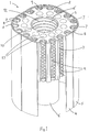
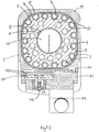
- a wick assembly 1 of an anaesthetic vaporiser comprises a wick core block 2 of aluminium alloy, an inner wick 3, a main wick 4, an outer wick 5 and a centre wick 6, each wick 3-6 comprising a needle felt wick material made from polytetrafluoroethylene fibres.
- the wick core block 2 is generally cube-shaped, with its edges extending vertically, in use, being substantially rounded.
- a plurality of channels 7 (in this embodiment, seventeen) extend vertically through the vertical faces of the core block 2, separated by a plurality of ribs 8.
- Each channel 7 has a generally ⁇ - shaped profile.
- the inner wick 3 comprises a sheet of wick material extending around the vertical faces of the core block 2 so as to follow the profile of each channel 7 and rib 8.
- a helical spring 9 extends along an interior of each channel 7, acting as a frame to hold a respective portion of the inner wick 3 in contact with an interior surface of the channel 7. The inner wick 3 thus lines each channel 7 and is contactable by gas passing therethrough.
- the main wick 4 extends around the vertical faces of the core block 2 exterior of the channels 7, contacting the inner wick 3 where it passes over the ribs 8.
- the main wick 4 also extends downwardly below the wick core block 2, so that it may pick up liquid anaesthetic agent from a reservoir (see below).
- the outer wick 5 extends around an outside of the main wick 4. It may either also extend downwardly below the core block 2, as shown in Figure 1 , or have a vertical extent generally similar to that of the core block 2 and the inner wick 3, as shown in Figure 2 .
- the core block 2 is also provided with a substantially cylindrical central aperture 10, extending vertically therethrough.
- the centre wick 6 extends around a majority of an inner surface of the central aperture 10, having the form of a hollow elongate cylinder with a longitudinal slot 11, and also extends downwardly below the core block 2 so that it may pick up liquid anaesthetic agent from the reservoir.
- the centre wick 6 is held in contact with the inner surface of the central aperture 10 by a helical central spring 12 of corresponding dimensions.
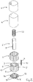
- the wick assembly 1 also comprises a base plate 13 (omitted from Figure 1 for clarity). This is fastened to an underside of the core block 2, fitting within the main wick 4.
- the base plate has a central aperture 14, corresponding to the central aperture 10 of the core block 2, through which the centre wick 6 passes.
- the base plate 13 is provided on its upper face with an outer set of elongate recesses 15 and an inner set of elongate recesses 16, whose function is described below.
- the core block 2 is also provided with a plurality of cylindrical passages 17 (in this embodiment, twelve) extending vertically therethrough, located between the channels 7 and the central aperture 10.
- the wick assembly 1 fits closely inside a reservoir chamber 18, located within a main body 19 of the vaporiser.
- the main wick 4 and outer wick 5 are held securely between the core block 2 and corresponding walls of the reservoir chamber 18.
- each channel 7 adopts a generally cylindrical form, entirely lined with wick material.
- a lower zone 20 of the reservoir chamber 18 is filled, in use, with a supply of a liquid anaesthetic agent.
- the main wick 4 and centre wick 6 (and optionally the outer wick 5) extend into the lower zone 20.
- liquid anaesthetic agent passes upwardly throughout the main wick 4 and centre wick 6.
- An upper manifold block 21, as shown in Figure 4 is mounted to an upper surface of the wick assembly 1 and main body 19.
- the upper manifold block 21 is provided on its surface facing the wick core block 2 with an outer set of elongate recesses 22 and an inner set of elongate recesses 23.
- one channel 7a is provided with a groove 24 extending longitudinally thereof, to receive overlapping extremities of the inner wick 3.
- the main wick 4 also overlaps with itself at its extremities, as shown, and so the outer wick 5 is sized to leave a gap between its extremities, which receives the overlapping extremities of the main wick 4.
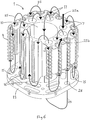
- the wick assembly 1 defines a prolonged path in contact with anaesthetic-soaked wick material, along which carrier gas is passed to become fully saturated with anaesthetic vapour.
- Figure 6 shows this gas path, which follows the sequence of arrows 25.
- Carrier gas enters the wick assembly 1 from an entry port 26 of the upper manifold block 21 (see Figure 4 ), flowing into a passage 17 aligned with the entry port 26, along arrow 25a. At a lower end, this passage 17 is aligned with one of the inner set of elongate recesses 16 of the base plate 13, which connects it to a lower end of an adjacent passage 17. An upper end of the adjacent passage 17 is aligned with one of the inner set of elongate recesses 23 of the upper manifold block 21, which in turn connects it to an upper end of a further passage 17. Thus, the carrier gas flows alternately upwardly and downwardly through each of the passages 17.
- a last elongate recess 27 in the upper manifold block 21 connects a final one of the passages 17 to the central aperture 10 of the core block 2.
- carrier gas absorbs, as it flows downwardly, anaesthetic vapour from the centre wick 6.
- the slot 11 in the centre wick 6 allows the gas to pass outwardly of the wick 6, above a point where the wick 6 enters the liquid anaesthetic held in the lower zone 20 of the reservoir chamber 18.
- the carrier gas then passes upwardly through a passage port 28 extending through the base plate 13, and enters a channel 7 aligned therewith.
- An upper end of the channel 7 is linked via one of the outer set of elongate recesses 22 of the upper manifold block 21 to an upper end of an adjacent channel 7.
- the lower end of this adjacent channel 7 is similarly linked by one of the outer set of elongate recesses 15 of the base plate 13 to a lower end of a further channel 7, and so forth.
- the carrier gas flows alternately upwardly and downwardly through each of the channels 7.
- carrier gas exiting a final one of the channels 7, along arrow 25b, and being led away through an exit port 29 in the upper manifold block 21 aligned therewith, is reliably fully saturated with anaesthetic vapour.
- the use of a mechanical ventilator to deliver an ultimate anaesthetic blend to a patient may cause pulsations in back-pressure in the carrier gas stream, as far back in the anaesthetic delivery system as the vaporiser.
- This can affect both carrier gas flow patterns and the saturated vapour pressure of the anaesthetic vapour in the carrier gas, leading to undesirable variations in the supply of anaesthetic vapour and carrier gas from the vaporiser.
- the vaporiser shown is a by-pass type vaporiser, in which an incoming carrier gas stream is divided into two, one sub-stream being passed through a wick arrangement to become saturated with anaesthetic vapour and the other sub-stream by-passing the wick arrangement.
- the carrier gas stream produced thus has a known partially-saturated anaesthetic vapour content.
- any wick arrangement even the wick assembly 1 of the present invention, will cool to some extent when in use.
- the saturated vapour pressure of anaesthetic in the carrier gas will thus fall until the vaporiser reaches an equilibrium operating temperature.
- more of the carrier gas must be routed through the wick assembly to pick up anaesthetic and less must by-pass it.
- a temperature compensating valve into the path of the carrier gas by-passing the wick.
- This valve incorporates a bimetallic strip which closes the valve as it cools, restricting flow through the valve and diverting more of the carrier gas through the wick arrangement.
- this valve is mounted to an underside of the reservoir chamber 18, so that the bimetallic strip responds to the temperature of the liquid anaesthetic therein.
- the temperatures of the liquid anaesthetic in the reservoir and of the anaesthetic vapour in the wick arrangement can differ significantly.
- the vaporiser according to a preferred embodiment of the present invention is provided with a temperature compensating valve 30 mounted adjacent an upper part of the main body 19, and hence close to the wick assembly 1, its core block 2, and the carrier gas and anaesthetic vapour passing therethrough.
- the temperature compensating valve 30 is mounted to a front block 31 of the vaporiser. It comprises a pair of closely-spaced circular plates 32, the opposing faces which are machined to a very close tolerance. Carrier gas enters a volume between the plates 32 adjacent their centres and flows radially outwardly. A bimetallic strip 33 is so arranged that, as it cools, it bears on one of the plates 32, and moves them together. The plates 32 are springloaded so that they move apart again if the bimetallic strip 33 warms and retracts.
- the carrier gas entering the vaporiser is split into two within the upper manifold block 21.
- the sub-stream by-passing the wick assembly 1 flows out of a first by-pass port 35a in the upper mounting body (see Figure 7 ) and enters the front block 31 through its corresponding first by-pass port 36a, as shown by arrow 34a.
- the sub-stream then passes through the restricted volume between the plates 32, and leaves the front block 31 through a second by-pass port 36b, re-entering the upper manifold block 21 through its corresponding second by-pass port 35b, as shown by arrow 34b.
- This sub-stream is then recombined, within the upper manifold block 21, with the sub-stream that has passed through the wick assembly 1.
- This arrangement provides far more responsive compensation for any temperature variations within the wick assembly 1 than do conventional by-pass valve arrangements, and so delivers a significantly more consistent anaesthetic vapour concentration.
- valve 30 As the valve 30 is not occupying space within the main body 19 beneath the reservoir chamber 18, this can be deeper for a given overall height of the vaporiser. Also, with the valve 30 occupying only an upper part of the front block 31, a lower part of the front block 31 can be hollowed out to form an extension 37 of the reservoir chamber 18, further increasing the capacity of the vaporiser without exceeding its maximum possible external dimensions.
- the embodiment shown has a capacity of 400cm 3 ; equivalent conventional vaporisers can hold no more than 250cm 3 .
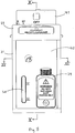
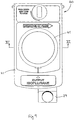
- Figures 8 and 9 show the assembled vaporiser.
- a sight glass 38 is provided, allowing direct visualisation of the level of liquid anaesthetic in the reservoir chamber 18 and its extension 37.
- the sight glass 38 is provided with indicia showing a maximum fill level and a minimum fill level, below which the reservoir chamber 18 requires urgent replenishment.
- a pour filler unit 39 of conventional form, is provided, mounted to the front block 31 and connected to the extension 37. This allows easy topping-up of the reservoir chamber 18 while the vaporiser is in use. Alternative filling systems can be used in place of the pour filler unit 39 shown.
- the vaporiser shown has a conventional mounting arrangement 40 incorporated into the upper manifold block 21, so that it may be mounted to a desired existing mounting rack system (in this case, a Selectatec (Registered Trade Mark) system).
- a desired existing mounting rack system in this case, a Selectatec (Registered Trade Mark) system.
- the net anaesthetic vapour content provided by the vaporiser is controlled by a conventional control valve arrangement within the upper manifold block 21, and is set by means of a control knob 41.
- Figures 10 to 12 show the assembled vaporiser in cross-section.
- Figure 12 shows how close the bimetallic strip 33 of the temperature compensating valve 30 is to the wick assembly 1 and the channels 7 therethrough, ensuring that it responds reliably to the actual temperature of the carrier gas and anaesthetic vapour therein.
- Figure 12 also shows an adjusting body 32 for fine adjustment of the valve 30, and 42 for setting the maximum bypass resistance, easily accessible by removing a decorative fascia 43 from the front block 31.
- the vaporiser shown provides a supply of anaesthetic vapour, borne in a stream of carrier gas, having a consistent, predetermined anaesthetic content. It undergoes lower temperature variations during operations than do existing vaporisers, and compensates more accurately and rapidly for any variations that do occur. It is easy to keep topped up during prolonged use, and in any case has a significantly greater anaesthetic capacity while having external dimensions compatible with existing mountings. It also has an in-built resistance to "pumping" effects due to mechanical ventilators connected thereto, and the anti-pumping design of the core also provides improved heat transfer.
Landscapes
- Health & Medical Sciences (AREA)
- Anesthesiology (AREA)
- Emergency Medicine (AREA)
- Pulmonology (AREA)
- Engineering & Computer Science (AREA)
- Biomedical Technology (AREA)
- Heart & Thoracic Surgery (AREA)
- Hematology (AREA)
- Life Sciences & Earth Sciences (AREA)
- Animal Behavior & Ethology (AREA)
- General Health & Medical Sciences (AREA)
- Public Health (AREA)
- Veterinary Medicine (AREA)
- Feeding, Discharge, Calcimining, Fusing, And Gas-Generation Devices (AREA)
- Catching Or Destruction (AREA)
Claims (11)
- Narkosemittelverdampfer (1), umfassend ein Behältermittel (18), das zum Halten einer Zufuhr von flüssigem Narkosemittel ausgelegt ist, und gekennzeichnet ist durch mehrere beabstandete, sich im Allgemeinen parallel erstreckende Kanalmittel (7), die sich im Allgemeinen jeweils vertikal erstrecken, um im Gebrauch einen Pfad für durch den Verdampfer (1) durchlaufendes Trägergas zu definieren, und die jeweils mit einem jeweiligen Dochtmittel (3) versehen sind, das sich in das Behältermittel (18) erstreckt oder damit wirkverbunden ist, um zu ermöglichen, dass flüssiges Narkosemittel von dem Behältermittel (18) zu jedem Dochtmittel (3) strömt.
- Verdampfer (1) nach Anspruch 1, dadurch gekennzeichnet, dass die mehreren Kanalmittel (7) so verbunden sind, dass der Trägergasstrom entlang einiger der Kanalmittel (7) nach oben und entlang eines Rests davon nach unten, optional abwechselnd entlang aufeinanderfolgender Kanalmittel (7) nach oben und nach unten geleitet wird.
- Verdampfer (1) nach Anspruch 1 oder 2, dadurch gekennzeichnet, dass jedes Dochtmittel (3) eine Schicht aus Dochtmaterial umfasst, das wenigstens einen Teil einer Innenoberfläche eines entsprechenden Kanalmittels (7), optional einen Großteil davon, auskleidet.
- Verdampfer (1) nach Anspruch 3, dadurch gekennzeichnet, dass jedes Kanalmittel (7) mit einem Rahmenmittel (9) versehen ist, das ausgelegt ist, die Schicht aus Dochtmaterial auf der Oberfläche zu halten.
- Verdampfer (1) nach Anspruch 4, dadurch gekennzeichnet, dass jedes Kanalmittel (7) eine längliche, im Allgemeinen zylindrische Form aufweist und die Rahmenmittel (9) ein Schraubenfedermittel (9) umfassen, das bemessen ist, in ein jeweiliges Kanalmittel (7) einführbar zu sein, wobei das Dochtmaterial zwischen diesem und der Innenoberfläche des Kanalmittels (7) gehalten wird.
- Verdampfer (1) nach einem der vorhergehenden Ansprüche, dadurch gekennzeichnet, dass die Dochtmittel (3) durch eine Lage aus zweitem Dochtmaterial (4), das sich in das Behältermittel (18) hinein erstreckt und optional einen Teil der Innenoberfläche jedes Kanalmittels (7) auskleidet und jedes Dochtmittel (3) berührt, mit dem Behältermittel (18) wirkverbunden sind.
- Verdampfer (1) nach einem der vorhergehenden Ansprüche, dadurch gekennzeichnet, dass er ferner obere (21) und untere (13) Endkappen umfasst, die jeweils mit einem Durchlassmittel (22, 15) versehen sind, um ein jeweiliges Ende jedes Kanalmittels (7) mit einem jeweiligen Ende eines anderen Kanalmittels (7), oder mit einem Einlass(28)- oder Auslass(29)-Mittel für das Trägergas zu verbinden.
- Narkosemittelverdampfer (1) nach einem der vorhergehenden Ansprüche, dadurch gekennzeichnet, dass er ferner Folgendes umfasst: einen zweiten Trägergaspfad, der einen Kontakt zwischen Trägergas und Narkosedampf verhindert, und ein temperaturempfindliches Ventilmittel (30), das ausgelegt ist, das Verhältnis von entlang jedes Pfads strömendem Trägergas zu regeln, wobei das Ventilmittel (30) derart angebracht ist, dass es die Temperatur von Trägergas und Narkosedampf neben einem oberen Teil des Behältermittels (18) erfasst und auf diese reagiert.
- Verdampfer (1) nach Anspruch 8, dadurch gekennzeichnet, dass das Ventilmittel (30) eine variable Begrenzung im zweiten Trägergaspfad umfasst, optional ein Paar von Plattenmitteln (32), zwischen denen das Trägergas beschränkt ist, zu strömen, und durch eine Trennung, die durch Bewegen eines Bimetallstreifenmittels (33) geregelt ist, beabstandet.
- Narkosemittelverdampfer (1) nach einem der vorhergehenden Ansprüche, dadurch gekennzeichnet, dass er ferner einen dritten Trägergaspfad umfasst, der einen mit einem Eingang (28) verbundenen Ausgang (27) zum ersten Trägergaspfad aufweist und sich derart daran angrenzend erstreckt, dass Wärme vom Trägergas im dritten Pfad in ein Trägergas im ersten Pfad strömen kann, um jene durch Verdampfen eines Anästhetikums verlorene Wärme zu ersetzen.
- Verdampfer (1) nach einem der vorhergehenden Ansprüche, dadurch gekennzeichnet, dass er ferner ein Puffermittel umfasst, um die Wirkungen von Abweichungen im Gegendruck, wie etwa durch einen mechanischen Ventilator erzeugt, der damit wirkverbunden ist, zu verhindern, wobei das Puffermittel einen länglichen indirekten Trägergaspfad im Verdampfer (1) umfasst.
Applications Claiming Priority (2)
| Application Number | Priority Date | Filing Date | Title |
|---|---|---|---|
| GB0326298A GB2408208B (en) | 2003-11-11 | 2003-11-11 | Anaesthetic vaporiser |
| GB0326298 | 2003-11-11 |
Publications (2)
| Publication Number | Publication Date |
|---|---|
| EP1530980A1 EP1530980A1 (de) | 2005-05-18 |
| EP1530980B1 true EP1530980B1 (de) | 2018-01-03 |
Family
ID=29726339
Family Applications (1)
| Application Number | Title | Priority Date | Filing Date |
|---|---|---|---|
| EP04256741.2A Expired - Lifetime EP1530980B1 (de) | 2003-11-11 | 2004-11-01 | Narkosemittelverdunster |
Country Status (3)
| Country | Link |
|---|---|
| US (1) | US20050133030A1 (de) |
| EP (1) | EP1530980B1 (de) |
| GB (4) | GB2436945B (de) |
Families Citing this family (14)
| Publication number | Priority date | Publication date | Assignee | Title |
|---|---|---|---|---|
| GB2436945B (en) * | 2003-11-11 | 2008-04-02 | Richard John Fiedorowicz | Anaesthetic vaporiser |
| DE102005012340B3 (de) * | 2005-03-17 | 2006-05-11 | Dräger Medical AG & Co. KG | Anästhesiesystem mit einem Narkosemittelverdunster |
| US8459259B2 (en) | 2007-07-31 | 2013-06-11 | Resmed Limited | Heating element, humidifier for respiratory apparatus including heating element, and respiratory apparatus |
| DE102008045081A1 (de) | 2008-08-29 | 2010-03-04 | Dräger Medical AG & Co. KG | Docht für einen Narkosemittelverdunster |
| CN101683544B (zh) * | 2008-09-28 | 2013-03-20 | 深圳迈瑞生物医疗电子股份有限公司 | 麻醉蒸发器 |
| CN101780302B (zh) * | 2009-01-16 | 2014-04-02 | 深圳迈瑞生物医疗电子股份有限公司 | 麻醉蒸发器及温度补偿单元 |
| US8267081B2 (en) | 2009-02-20 | 2012-09-18 | Baxter International Inc. | Inhaled anesthetic agent therapy and delivery system |
| DE102011010035B4 (de) * | 2011-02-02 | 2023-02-02 | Drägerwerk AG & Co. KGaA | Füllvorrichtung für einen Narkosemitteldosierer |
| KR101257818B1 (ko) * | 2011-05-30 | 2013-04-29 | 박준성 | 마취용 기화기 |
| TWI671091B (zh) * | 2014-03-13 | 2019-09-11 | 澳大利亞商瑞思邁私人股份有限公司 | 用於呼吸治療器件之增濕器 |
| CN105477762B (zh) * | 2014-09-15 | 2018-07-06 | 深圳市科曼医疗设备有限公司 | 麻醉蒸发器的芯子和麻醉蒸发器 |
| CN104474623B (zh) * | 2014-09-26 | 2017-03-29 | 中国人民解放军总医院 | 吸入式麻醉蒸发过滤装置 |
| DE102014017675A1 (de) * | 2014-11-28 | 2016-06-02 | Drägerwerk AG & Co. KGaA | Narkosemittelverdunster und Docht für einen Narkosemittelverdunster |
| DE102014018602A1 (de) * | 2014-12-17 | 2016-06-23 | Drägerwerk AG & Co. KGaA | Narkosemittelverdunstereinheit |
Family Cites Families (38)
| Publication number | Priority date | Publication date | Assignee | Title |
|---|---|---|---|---|
| US2731709A (en) * | 1950-09-18 | 1956-01-24 | Brown Fintube Co | Method of making internally finned heat exchanger tubes |
| GB758657A (en) * | 1953-07-30 | 1956-10-10 | Cyprane Ltd | Improvements in volatile anaesthetic vapourising apparatus |
| US2915061A (en) * | 1956-12-24 | 1959-12-01 | Cyprane Ltd | Volatile anaesthetic vaporising apparatus |
| NL290539A (de) * | 1961-11-18 | |||
| US3420232A (en) * | 1965-07-20 | 1969-01-07 | Foregger Co Inc | Anesthetic vaporizer |
| GB1088080A (en) * | 1966-07-01 | 1967-10-18 | Hutchinson Blease Ltd | Improvements in anaesthetic or analgesic vaporisers |
| US3385578A (en) * | 1966-09-28 | 1968-05-28 | Fraser Sweatman | Anesthesia apparatus |
| US3534732A (en) * | 1966-11-07 | 1970-10-20 | Foregger Co Inc | Anesthetic vaporizer |
| GB1230972A (de) * | 1967-05-31 | 1971-05-05 | ||
| GB1224478A (en) * | 1967-11-29 | 1971-03-10 | Cyprane Ltd | Improvements in volatile anaesthetic vapourising apparatus |
| DE1566631B1 (de) * | 1968-05-23 | 1970-05-27 | Draegerwerk Ag | Oberflaechenverdunster fuer die Verwendung in Narkosekreissystemen |
| GB1228036A (de) * | 1968-07-02 | 1971-04-15 | ||
| US3671024A (en) * | 1969-05-02 | 1972-06-20 | Draegerwerk Ag | Expansion temperature sensing means, in particular for medical apparatus |
| DE1924227C3 (de) * | 1969-05-12 | 1974-12-05 | Draegerwerk Ag, 2400 Luebeck | Narkosemittelverdunster |
| US3687137A (en) * | 1969-11-13 | 1972-08-29 | Donald W Johnson | Small animal anesthesia machine |
| US3734293A (en) * | 1970-03-04 | 1973-05-22 | Air Prod & Chem | Thermoelectric adsorber |
| US3841560A (en) * | 1973-07-16 | 1974-10-15 | Airco Inc | Anesthetic vaporizer |
| US3954920A (en) * | 1973-09-04 | 1976-05-04 | Parkland International Inc. | Gas humidification system |
| DE2507262C3 (de) * | 1975-02-20 | 1978-08-17 | Draegerwerk Ag, 2400 Luebeck | Narkosemittelverdunster |
| US4059657A (en) * | 1975-07-11 | 1977-11-22 | Airco, Inc. | Calibrated anesthetic vaporizer |
| US4067935A (en) * | 1976-01-02 | 1978-01-10 | Cyprane North America, Inc. | Volatile anesthetic vaporizing apparatus |
| US4121583A (en) * | 1976-07-13 | 1978-10-24 | Wen Yuan Chen | Method and apparatus for alleviating asthma attacks |
| GB2084469B (en) * | 1980-09-09 | 1984-02-01 | Medishield The Corp Ltd | Anaesthetic vaporiser |
| GB8510805D0 (en) * | 1985-04-29 | 1985-06-05 | Penlon Ltd | Vaporizing apparatus |
| DE3523947A1 (de) * | 1985-07-04 | 1987-01-08 | Draegerwerk Ag | Narkosemittelverdunster mit auswechselbarer verdunsterkammer |
| US4879997A (en) * | 1988-04-07 | 1989-11-14 | Bickford Allan M | Anesthetic vaporizer |
| GB2217610A (en) * | 1988-04-27 | 1989-11-01 | Boc Group Plc | Anaesthetic vaporisers |
| FI95351C (fi) * | 1990-12-18 | 1996-01-25 | Instrumentarium Oy Datex | Nestettä höyrystävä laite |
| US5645052A (en) * | 1991-04-26 | 1997-07-08 | The Boc Group Plc | Anaesthetic vaporizer with expandable/contractable reservoir for pumping liquid anaesthetic |
| US5349946A (en) * | 1992-10-07 | 1994-09-27 | Mccomb R Carter | Microprocessor controlled flow regulated molecular humidifier |
| US5609798A (en) * | 1995-06-07 | 1997-03-11 | Msp Corporation | High output PSL aerosol generator |
| US6021177A (en) * | 1995-06-29 | 2000-02-01 | Allport; Douglas C. | Community alarm/notification device, method and system |
| SE9700595L (sv) * | 1997-02-20 | 1998-07-27 | Siemens Elema Ab | Förgasarkarusell för narkosapparat |
| US6021777A (en) * | 1997-03-13 | 2000-02-08 | Anesta-Pac, Inc. | Portable anesthesia machine |
| GB9922634D0 (en) * | 1999-09-25 | 1999-11-24 | Penlon Ltd | Improved anaesthetic vaporizer |
| US6635114B2 (en) * | 1999-12-17 | 2003-10-21 | Applied Material, Inc. | High temperature filter for CVD apparatus |
| US6976489B2 (en) * | 2000-06-30 | 2005-12-20 | Northgate Technologies, Inc. | Method and apparatus for humidification and warming of air |
| GB2436945B (en) * | 2003-11-11 | 2008-04-02 | Richard John Fiedorowicz | Anaesthetic vaporiser |
-
2003
- 2003-11-11 GB GB0706373A patent/GB2436945B/en not_active Expired - Fee Related
- 2003-11-11 GB GB0706374A patent/GB2436946B/en not_active Expired - Fee Related
- 2003-11-11 GB GB0706375A patent/GB2436947B/en not_active Expired - Fee Related
- 2003-11-11 GB GB0326298A patent/GB2408208B/en not_active Expired - Fee Related
-
2004
- 2004-11-01 EP EP04256741.2A patent/EP1530980B1/de not_active Expired - Lifetime
- 2004-11-04 US US10/980,937 patent/US20050133030A1/en not_active Abandoned
Non-Patent Citations (1)
| Title |
|---|
| None * |
Also Published As
| Publication number | Publication date |
|---|---|
| GB0706375D0 (en) | 2007-05-09 |
| GB2436946A (en) | 2007-10-10 |
| EP1530980A1 (de) | 2005-05-18 |
| GB0706374D0 (en) | 2007-05-09 |
| GB2436945A (en) | 2007-10-10 |
| GB2408208A (en) | 2005-05-25 |
| US20050133030A1 (en) | 2005-06-23 |
| GB2436947A (en) | 2007-10-10 |
| GB2408208B (en) | 2008-04-02 |
| GB0706373D0 (en) | 2007-05-09 |
| GB2436947B (en) | 2009-03-25 |
| GB2436945B (en) | 2008-04-02 |
| GB0326298D0 (en) | 2003-12-17 |
| GB2436946B (en) | 2008-04-02 |
Similar Documents
| Publication | Publication Date | Title |
|---|---|---|
| EP1530980B1 (de) | Narkosemittelverdunster | |
| US4010748A (en) | Breathing air humidifier for respiration devices | |
| CA2033770C (en) | Anaesthetic vaporisers | |
| JP4338218B2 (ja) | 気化麻酔剤供給システム | |
| JPH05309136A (ja) | 呼吸ガス用加湿器 | |
| EP1007127B1 (de) | Gaszuführvorrichtung zur versorgung von behandlungsgas bei einer person oder einem tier | |
| US7694675B2 (en) | Respirator humidifier | |
| EP0449545B1 (de) | Narkosemittelverdunster | |
| JPS6317468B2 (de) | ||
| LT5310B (lt) | Sistema, skirta drėkintuvo užpildymui vandeniu | |
| DK168939B1 (da) | Bedøvelsesmiddelfordamper | |
| US6021777A (en) | Portable anesthesia machine | |
| EP0965372A2 (de) | Verdampfer | |
| US5490500A (en) | Anesthetic evaporator with intermediate container | |
| CA2033772C (en) | Anaesthetic vaporisers | |
| Dhulkhed et al. | Vapourisers: physical principles and classification | |
| EP0454390A1 (de) | Narkosemittelverdunster | |
| US5372127A (en) | Sump for an anaesthetic vaporiser | |
| SU939017A1 (ru) | Испаритель наркотизирующих веществ | |
| GB2279015A (en) | Vaporizer flow path | |
| RU2497553C1 (ru) | Испаритель анестетиков | |
| GB2355666A (en) | Anaesthetic vaporizer |
Legal Events
| Date | Code | Title | Description |
|---|---|---|---|
| PUAI | Public reference made under article 153(3) epc to a published international application that has entered the european phase |
Free format text: ORIGINAL CODE: 0009012 |
|
| AK | Designated contracting states |
Kind code of ref document: A1 Designated state(s): AT BE BG CH CY CZ DE DK EE ES FI FR GB GR HU IE IS IT LI LU MC NL PL PT RO SE SI SK TR |
|
| AX | Request for extension of the european patent |
Extension state: AL HR LT LV MK YU |
|
| 17P | Request for examination filed |
Effective date: 20051031 |
|
| AKX | Designation fees paid |
Designated state(s): AT BE BG CH CY CZ DE DK EE ES FI FR GB GR HU IE IS IT LI LU MC NL PL PT RO SE SI SK TR |
|
| 17Q | First examination report despatched |
Effective date: 20070626 |
|
| 18D | Application deemed to be withdrawn |
Effective date: 20080603 |
|
| 18RA | Request filed for re-establishment of rights before grant |
Effective date: 20081218 |
|
| 19U | Interruption of proceedings before grant |
Effective date: 20071001 |
|
| 19W | Proceedings resumed before grant after interruption of proceedings |
Effective date: 20090709 |
|
| D18D | Application deemed to be withdrawn (deleted) | ||
| R17C | First examination report despatched (corrected) |
Effective date: 20090709 |
|
| R17C | First examination report despatched (corrected) |
Effective date: 20070626 |
|
| GRAP | Despatch of communication of intention to grant a patent |
Free format text: ORIGINAL CODE: EPIDOSNIGR1 |
|
| STAA | Information on the status of an ep patent application or granted ep patent |
Free format text: STATUS: GRANT OF PATENT IS INTENDED |
|
| INTG | Intention to grant announced |
Effective date: 20170502 |
|
| GRAS | Grant fee paid |
Free format text: ORIGINAL CODE: EPIDOSNIGR3 |
|
| GRAA | (expected) grant |
Free format text: ORIGINAL CODE: 0009210 |
|
| STAA | Information on the status of an ep patent application or granted ep patent |
Free format text: STATUS: THE PATENT HAS BEEN GRANTED |
|
| AK | Designated contracting states |
Kind code of ref document: B1 Designated state(s): AT BE BG CH CY CZ DE DK EE ES FI FR GB GR HU IE IS IT LI LU MC NL PL PT RO SE SI SK TR |
|
| REG | Reference to a national code |
Ref country code: CH Ref legal event code: EP Ref country code: AT Ref legal event code: REF Ref document number: 959660 Country of ref document: AT Kind code of ref document: T Effective date: 20180115 |
|
| REG | Reference to a national code |
Ref country code: IE Ref legal event code: FG4D |
|
| REG | Reference to a national code |
Ref country code: DE Ref legal event code: R096 Ref document number: 602004052244 Country of ref document: DE |
|
| REG | Reference to a national code |
Ref country code: NL Ref legal event code: MP Effective date: 20180103 |
|
| REG | Reference to a national code |
Ref country code: AT Ref legal event code: MK05 Ref document number: 959660 Country of ref document: AT Kind code of ref document: T Effective date: 20180103 |
|
| PG25 | Lapsed in a contracting state [announced via postgrant information from national office to epo] |
Ref country code: NL Free format text: LAPSE BECAUSE OF FAILURE TO SUBMIT A TRANSLATION OF THE DESCRIPTION OR TO PAY THE FEE WITHIN THE PRESCRIBED TIME-LIMIT Effective date: 20180103 |
|
| PG25 | Lapsed in a contracting state [announced via postgrant information from national office to epo] |
Ref country code: CY Free format text: LAPSE BECAUSE OF FAILURE TO SUBMIT A TRANSLATION OF THE DESCRIPTION OR TO PAY THE FEE WITHIN THE PRESCRIBED TIME-LIMIT Effective date: 20180103 Ref country code: ES Free format text: LAPSE BECAUSE OF FAILURE TO SUBMIT A TRANSLATION OF THE DESCRIPTION OR TO PAY THE FEE WITHIN THE PRESCRIBED TIME-LIMIT Effective date: 20180103 Ref country code: FI Free format text: LAPSE BECAUSE OF FAILURE TO SUBMIT A TRANSLATION OF THE DESCRIPTION OR TO PAY THE FEE WITHIN THE PRESCRIBED TIME-LIMIT Effective date: 20180103 |
|
| PG25 | Lapsed in a contracting state [announced via postgrant information from national office to epo] |
Ref country code: SE Free format text: LAPSE BECAUSE OF FAILURE TO SUBMIT A TRANSLATION OF THE DESCRIPTION OR TO PAY THE FEE WITHIN THE PRESCRIBED TIME-LIMIT Effective date: 20180103 Ref country code: AT Free format text: LAPSE BECAUSE OF FAILURE TO SUBMIT A TRANSLATION OF THE DESCRIPTION OR TO PAY THE FEE WITHIN THE PRESCRIBED TIME-LIMIT Effective date: 20180103 Ref country code: PL Free format text: LAPSE BECAUSE OF FAILURE TO SUBMIT A TRANSLATION OF THE DESCRIPTION OR TO PAY THE FEE WITHIN THE PRESCRIBED TIME-LIMIT Effective date: 20180103 Ref country code: IS Free format text: LAPSE BECAUSE OF FAILURE TO SUBMIT A TRANSLATION OF THE DESCRIPTION OR TO PAY THE FEE WITHIN THE PRESCRIBED TIME-LIMIT Effective date: 20180503 Ref country code: GR Free format text: LAPSE BECAUSE OF FAILURE TO SUBMIT A TRANSLATION OF THE DESCRIPTION OR TO PAY THE FEE WITHIN THE PRESCRIBED TIME-LIMIT Effective date: 20180404 Ref country code: BG Free format text: LAPSE BECAUSE OF FAILURE TO SUBMIT A TRANSLATION OF THE DESCRIPTION OR TO PAY THE FEE WITHIN THE PRESCRIBED TIME-LIMIT Effective date: 20180403 |
|
| REG | Reference to a national code |
Ref country code: DE Ref legal event code: R097 Ref document number: 602004052244 Country of ref document: DE |
|
| PG25 | Lapsed in a contracting state [announced via postgrant information from national office to epo] |
Ref country code: IT Free format text: LAPSE BECAUSE OF FAILURE TO SUBMIT A TRANSLATION OF THE DESCRIPTION OR TO PAY THE FEE WITHIN THE PRESCRIBED TIME-LIMIT Effective date: 20180103 Ref country code: EE Free format text: LAPSE BECAUSE OF FAILURE TO SUBMIT A TRANSLATION OF THE DESCRIPTION OR TO PAY THE FEE WITHIN THE PRESCRIBED TIME-LIMIT Effective date: 20180103 |
|
| PLBE | No opposition filed within time limit |
Free format text: ORIGINAL CODE: 0009261 |
|
| STAA | Information on the status of an ep patent application or granted ep patent |
Free format text: STATUS: NO OPPOSITION FILED WITHIN TIME LIMIT |
|
| PG25 | Lapsed in a contracting state [announced via postgrant information from national office to epo] |
Ref country code: CZ Free format text: LAPSE BECAUSE OF FAILURE TO SUBMIT A TRANSLATION OF THE DESCRIPTION OR TO PAY THE FEE WITHIN THE PRESCRIBED TIME-LIMIT Effective date: 20180103 Ref country code: DK Free format text: LAPSE BECAUSE OF FAILURE TO SUBMIT A TRANSLATION OF THE DESCRIPTION OR TO PAY THE FEE WITHIN THE PRESCRIBED TIME-LIMIT Effective date: 20180103 Ref country code: SK Free format text: LAPSE BECAUSE OF FAILURE TO SUBMIT A TRANSLATION OF THE DESCRIPTION OR TO PAY THE FEE WITHIN THE PRESCRIBED TIME-LIMIT Effective date: 20180103 |
|
| 26N | No opposition filed |
Effective date: 20181005 |
|
| PG25 | Lapsed in a contracting state [announced via postgrant information from national office to epo] |
Ref country code: SI Free format text: LAPSE BECAUSE OF FAILURE TO SUBMIT A TRANSLATION OF THE DESCRIPTION OR TO PAY THE FEE WITHIN THE PRESCRIBED TIME-LIMIT Effective date: 20180103 |
|
| PG25 | Lapsed in a contracting state [announced via postgrant information from national office to epo] |
Ref country code: LU Free format text: LAPSE BECAUSE OF NON-PAYMENT OF DUE FEES Effective date: 20181101 Ref country code: MC Free format text: LAPSE BECAUSE OF FAILURE TO SUBMIT A TRANSLATION OF THE DESCRIPTION OR TO PAY THE FEE WITHIN THE PRESCRIBED TIME-LIMIT Effective date: 20180103 |
|
| REG | Reference to a national code |
Ref country code: BE Ref legal event code: MM Effective date: 20181130 |
|
| REG | Reference to a national code |
Ref country code: IE Ref legal event code: MM4A |
|
| PG25 | Lapsed in a contracting state [announced via postgrant information from national office to epo] |
Ref country code: IE Free format text: LAPSE BECAUSE OF NON-PAYMENT OF DUE FEES Effective date: 20181101 |
|
| PG25 | Lapsed in a contracting state [announced via postgrant information from national office to epo] |
Ref country code: BE Free format text: LAPSE BECAUSE OF NON-PAYMENT OF DUE FEES Effective date: 20181130 |
|
| PG25 | Lapsed in a contracting state [announced via postgrant information from national office to epo] |
Ref country code: TR Free format text: LAPSE BECAUSE OF FAILURE TO SUBMIT A TRANSLATION OF THE DESCRIPTION OR TO PAY THE FEE WITHIN THE PRESCRIBED TIME-LIMIT Effective date: 20180103 |
|
| PG25 | Lapsed in a contracting state [announced via postgrant information from national office to epo] |
Ref country code: PT Free format text: LAPSE BECAUSE OF FAILURE TO SUBMIT A TRANSLATION OF THE DESCRIPTION OR TO PAY THE FEE WITHIN THE PRESCRIBED TIME-LIMIT Effective date: 20180103 |
|
| PG25 | Lapsed in a contracting state [announced via postgrant information from national office to epo] |
Ref country code: RO Free format text: LAPSE BECAUSE OF FAILURE TO SUBMIT A TRANSLATION OF THE DESCRIPTION OR TO PAY THE FEE WITHIN THE PRESCRIBED TIME-LIMIT Effective date: 20180103 Ref country code: HU Free format text: LAPSE BECAUSE OF FAILURE TO SUBMIT A TRANSLATION OF THE DESCRIPTION OR TO PAY THE FEE WITHIN THE PRESCRIBED TIME-LIMIT; INVALID AB INITIO Effective date: 20041101 |
|
| PGFP | Annual fee paid to national office [announced via postgrant information from national office to epo] |
Ref country code: GB Payment date: 20201030 Year of fee payment: 17 Ref country code: FR Payment date: 20201120 Year of fee payment: 17 Ref country code: CH Payment date: 20201118 Year of fee payment: 17 Ref country code: DE Payment date: 20201119 Year of fee payment: 17 |
|
| REG | Reference to a national code |
Ref country code: DE Ref legal event code: R119 Ref document number: 602004052244 Country of ref document: DE |
|
| REG | Reference to a national code |
Ref country code: CH Ref legal event code: PL |
|
| GBPC | Gb: european patent ceased through non-payment of renewal fee |
Effective date: 20211101 |
|
| PG25 | Lapsed in a contracting state [announced via postgrant information from national office to epo] |
Ref country code: LI Free format text: LAPSE BECAUSE OF NON-PAYMENT OF DUE FEES Effective date: 20211130 Ref country code: CH Free format text: LAPSE BECAUSE OF NON-PAYMENT OF DUE FEES Effective date: 20211130 |
|
| PG25 | Lapsed in a contracting state [announced via postgrant information from national office to epo] |
Ref country code: GB Free format text: LAPSE BECAUSE OF NON-PAYMENT OF DUE FEES Effective date: 20211101 Ref country code: DE Free format text: LAPSE BECAUSE OF NON-PAYMENT OF DUE FEES Effective date: 20220601 |
|
| PG25 | Lapsed in a contracting state [announced via postgrant information from national office to epo] |
Ref country code: FR Free format text: LAPSE BECAUSE OF NON-PAYMENT OF DUE FEES Effective date: 20211130 |