EP1530944B1 - Medizinisches Diagnostikgerät - Google Patents
Medizinisches Diagnostikgerät Download PDFInfo
- Publication number
- EP1530944B1 EP1530944B1 EP04019338A EP04019338A EP1530944B1 EP 1530944 B1 EP1530944 B1 EP 1530944B1 EP 04019338 A EP04019338 A EP 04019338A EP 04019338 A EP04019338 A EP 04019338A EP 1530944 B1 EP1530944 B1 EP 1530944B1
- Authority
- EP
- European Patent Office
- Prior art keywords
- battery
- sleeve
- handle
- medical diagnostic
- light
- Prior art date
- Legal status (The legal status is an assumption and is not a legal conclusion. Google has not performed a legal analysis and makes no representation as to the accuracy of the status listed.)
- Expired - Lifetime
Links
- 229920003023 plastic Polymers 0.000 claims abstract description 10
- 239000004033 plastic Substances 0.000 claims abstract description 10
- 239000002184 metal Substances 0.000 claims description 4
- 239000004020 conductor Substances 0.000 claims description 3
- 238000005286 illumination Methods 0.000 claims description 3
- 241000209035 Ilex Species 0.000 description 1
- 238000010276 construction Methods 0.000 description 1
- 238000009434 installation Methods 0.000 description 1
- 238000011835 investigation Methods 0.000 description 1
Images

Classifications
-
- A—HUMAN NECESSITIES
- A61—MEDICAL OR VETERINARY SCIENCE; HYGIENE
- A61B—DIAGNOSIS; SURGERY; IDENTIFICATION
- A61B1/00—Instruments for performing medical examinations of the interior of cavities or tubes of the body by visual or photographical inspection, e.g. endoscopes; Illuminating arrangements therefor
- A61B1/00064—Constructional details of the endoscope body
- A61B1/00105—Constructional details of the endoscope body characterised by modular construction
-
- A—HUMAN NECESSITIES
- A61—MEDICAL OR VETERINARY SCIENCE; HYGIENE
- A61B—DIAGNOSIS; SURGERY; IDENTIFICATION
- A61B1/00—Instruments for performing medical examinations of the interior of cavities or tubes of the body by visual or photographical inspection, e.g. endoscopes; Illuminating arrangements therefor
- A61B1/06—Instruments for performing medical examinations of the interior of cavities or tubes of the body by visual or photographical inspection, e.g. endoscopes; Illuminating arrangements therefor with illuminating arrangements
- A61B1/0661—Endoscope light sources
- A61B1/0669—Endoscope light sources at proximal end of an endoscope
-
- A—HUMAN NECESSITIES
- A61—MEDICAL OR VETERINARY SCIENCE; HYGIENE
- A61B—DIAGNOSIS; SURGERY; IDENTIFICATION
- A61B1/00—Instruments for performing medical examinations of the interior of cavities or tubes of the body by visual or photographical inspection, e.g. endoscopes; Illuminating arrangements therefor
- A61B1/06—Instruments for performing medical examinations of the interior of cavities or tubes of the body by visual or photographical inspection, e.g. endoscopes; Illuminating arrangements therefor with illuminating arrangements
- A61B1/0661—Endoscope light sources
- A61B1/0684—Endoscope light sources using light emitting diodes [LED]
-
- A—HUMAN NECESSITIES
- A61—MEDICAL OR VETERINARY SCIENCE; HYGIENE
- A61B—DIAGNOSIS; SURGERY; IDENTIFICATION
- A61B1/00—Instruments for performing medical examinations of the interior of cavities or tubes of the body by visual or photographical inspection, e.g. endoscopes; Illuminating arrangements therefor
- A61B1/227—Instruments for performing medical examinations of the interior of cavities or tubes of the body by visual or photographical inspection, e.g. endoscopes; Illuminating arrangements therefor for ears, i.e. otoscopes
Definitions
- the invention relates to a medical diagnostic device with lighting, wherein the device consists of a, the batteries receiving handle or the like and a patch on this head.
- the device consists of a, the batteries receiving handle or the like and a patch on this head.
- the incandescent lamps have a relatively high power consumption and also emit disturbing heat in the investigation.
- Light emitting diodes on the other hand, emit barely noticeable heat, absorb relatively little current and have an exceptionally long service life.
- the light-emitting diodes require a switching converter to be powered by the standard batteries can.
- the switching converter is arranged in the head or in the neck part of the device.
- the sleeve has the shape of a commercially available battery and has a metal shell on the outside, is closed at the top by a plastic bushing and receives below a plastic base on which the switching converter is supported.
- the plastic bushing is provided with a passage for current conductors.
- the sleeve is connected at its lower end via a contact surface with the one pole and laterally via a line extending within the handle with the other pole of the battery.
- the handle can now be used for all types of diagnostic equipment with a variety of light sources and in different sizes.
- the handles are usually designed for receiving at least two batteries.
- Another advantage of the sleeve is that it can be easily replaced by the user and incorrect installation is virtually eliminated. Of particular importance is that even the usual hand grips can still be used without any change.
- the light-emitting diode or the LEDs can be arranged in the head and connected via current-carrying lines to the switching converter in the sleeve.
- the sleeve may have one or more light-emitting diodes at its end facing the head, in which case the light beam is fed to the head via one or more light guides. It is expedient to arrange the light-emitting diode or the LEDs in the sleeve, wherein they protrude through one or more recesses thereof.
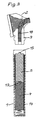
- FIGS. 1 and 2 Otoscope shown consists of a handle 1 for receiving batteries and a head 2 with neck 3, which is attachable to the handle 1.
- a handle 1 for receiving batteries and a head 2 with neck 3, which is attachable to the handle 1.
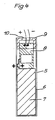
- Fig. 2 takes the handle 1 in the lower part of a battery 4, while in the upper part instead of a second battery a the dimensions of a battery adapted sleeve 5 is arranged.
- sleeve 5 has an outer, metal jacket 6, which receives a plastic base 7 in the lower part.
- a switching converter 8 is supported, which adapts the voltage supplied by the battery 4 to the voltage required for a light-emitting diode.
- In the upper part of the sleeve 5 is closed by a plastic plug 9. This has a recess 10 for the passage of electrical leads 11, which to the light emitting diode 12 (FIG. Fig. 2 ) in head 2.
- the switching converter 8 is from the battery 4 fed by concern of the positive pole 13 of the same on the metal shell 6 and the negative terminal via the conductor 14.
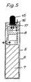
- the LED 15 is not in the head, but how Fig. 5 shows, arranged directly on the sleeve 5.
- the plastic plug 9 has a larger recess 16, through which the light-emitting diode 15 protrudes, which is connected at the bottom by lines 17 to the switching converter 8. The light emitted by this light-emitting diode 15 is thereby fed via light guide 18 through the neck 3 to the head 2.
Landscapes
- Health & Medical Sciences (AREA)
- Life Sciences & Earth Sciences (AREA)
- Surgery (AREA)
- Physics & Mathematics (AREA)
- Engineering & Computer Science (AREA)
- Optics & Photonics (AREA)
- Medical Informatics (AREA)
- General Health & Medical Sciences (AREA)
- Pathology (AREA)
- Nuclear Medicine, Radiotherapy & Molecular Imaging (AREA)
- Biomedical Technology (AREA)
- Heart & Thoracic Surgery (AREA)
- Biophysics (AREA)
- Molecular Biology (AREA)
- Animal Behavior & Ethology (AREA)
- Radiology & Medical Imaging (AREA)
- Public Health (AREA)
- Veterinary Medicine (AREA)
- Microelectronics & Electronic Packaging (AREA)
- Endoscopes (AREA)
- Apparatus For Radiation Diagnosis (AREA)
- Arrangement Of Elements, Cooling, Sealing, Or The Like Of Lighting Devices (AREA)
- Magnetic Resonance Imaging Apparatus (AREA)
- Ultra Sonic Daignosis Equipment (AREA)
- Measuring And Recording Apparatus For Diagnosis (AREA)
Description
- Die Erfindung bezieht sich auf ein medizinisches Diagnostikgerät mit Beleuchtung, wobei das Gerät aus einem, die Batterien aufnehmenden Handgriff oder dergleichen und einem auf diesem aufgesetzten Kopf besteht. Es ist bereits bekannt, zur Beleuchtung statt der bisher üblichen herkömmlichen Glühlampen Leuchtdioden zu verwenden, da die Glühlampen einen relativ hohen Strombedarf haben und auch störende Wärme bei der Untersuchung abstrahlen. Leuchtdioden geben dagegen eine kaum spürbare Wärme ab, nehmen relativ wenig Strom auf und haben eine außerordentlich lange Lebensdauer. Die Leuchtdioden benötigen allerdings einen Schaltwandler, um von den handelsüblichen Batterien gespeist werden zu können. Bei bekannten Ausführungsformen ist dabei der Schaltwandler im Kopf bzw. im Halsteil des Gerätes angeordnet.
- Aus der
GB--2 374 402 WO 2004/084716 A (Dokument nach Artikel 54(3) EPÜ), in der die Hülse als Batterie gestaltet ist. - Um den Aufbau eines solchen Gerätes zu vereinfachen weist erfindungsgemäß die Hülse die Form einer handelsüblichen Batterie auf und weist außen einen aus Metall bestehenden Mantel auf, ist oben durch eine Kunststoffbuchse abgeschlossen und nimmt unten einen Kunststoffsockel auf, auf welchem sich der Schaltwandler abstützt.
- Vorzugsweise ist die Kunststoffbuchse mit einem Durchtritt für Stromleiter versehen. Ferner ist es zweckmässig, dass die Hülse an ihrem unteren Ende über eine Kontaktfläche mit dem einen Pol und seitlich über eine innerhalb des Handgriffes verlaufende Leitung mit dem anderen Pol der Batterie verbunden ist.
- Der Handgriff kann nunmehr für alle Arten von Diagnostikgeräten mit den verschiedensten Lichtquellen und in unterschiedlichen Größen verwendet werden.
- Die Handgriffe sind üblicherweise für die Aufnahme von mindestens zwei Batterien ausgebildet. Man kann daher den gleichen Handgriff sowohl mit zwei oder mehreren Batterien für Geräte mit herkömmlichen Glühlampen als auch mit einer Hülse mit Schaltwandler und einer Batterie weniger für Leuchtdioden verwenden. Da, wie bereits oben erwähnt, Leuchtdioden wesentlich weniger Strom als eine Glühlampe verbrauchen, kann bei der Anwendung von Leuchtdioden durchaus auf eine Batterie verzichtet werden. Ein weiterer Vorteil der Hülse ist es, dass sie auch durch den Benutzer leicht ausgewechselt werden kann und ein falscher Einbau praktisch ausgeschlossen ist. Vor allem von Bedeutung ist es, dass auch die bisher üblichen Handgriffe nach wie vor ohne jede Änderung weiterverwendet werden können.
- Die Leuchtdiode oder die Leuchtdioden können im Kopf angeordnet und über stromführende Leitungen mit dem Schaltwandler in der Hülse verbunden sein. Bei einem anderen Ausführungsbeispiel der Erfindung kann die Hülse außer dem Schaltwandler ein oder mehrere Leuchtdioden an ihrem zum Kopf gerichteten Ende aufweisen, wobei dann der Lichtstrahl über ein oder mehrere Lichtleiter dem Kopf zugeführt wird. Dabei ist es zweckmässig die Leuchtdiode bzw. die Leuchtdioden in der Hülse anzuordnen, wobei sie durch ein oder mehrere Ausnehmungen derselben hindurchragen.
- Die Zeichnung zeigt ein Ausführungsbeispiel der Erfindung. Es stellen dar:
- Figur 1
- die Ansicht eines Otoskops, wobei der Kopf mit Hals vom Handgriff getrennt ist,
- Figur 2
- einen Querschnitt nach
Fig. 1 , - Figur 3
- einen Querschnitt nach
Fig. 2 einer anderen Ausführungsform, - Figur 4
- einen Querschnitt durch eine Hülse nach
Fig. 2 mit Schaltwandler in vergrößertem Maßstab, - Figur 5
- einen Querschnitt nach
Fig. 4 einer Ausführungsform nachFig. 3 . - Das in den
Fign. 1 und 2 dargestellte Otoskop besteht aus einem Handgriff 1 zur Aufnahme von Batterien und einem Kopf 2 mit Hals 3, welcher auf den Handgriff 1 aufsteckbar ist. Im Ausführungsbeispiel nachFig. 2 nimmt der Handgriff 1 im unteren Teil eine Batterie 4 auf, während im oberen Teil statt einer zweiten Batterie eine den Abmessungen einer Batterie angepasste Hülse 5 angeordnet ist. - Die in
Fig. 4 dargestellte Hülse 5 weist einen äußeren, aus Metall bestehenden Mantel 6 auf, welcher im unteren Teil einen Kunststoffsockel 7 aufnimmt. Auf diesem stützt sich ein Schaltwandler 8 ab, welcher die von der Batterie 4 zugeführte Spannung an die für eine Leuchtdiode erforderliche anpasst. Im oberen Teil ist die Hülse 5 durch einen Kunststoffstopfen 9 abgeschlossen. Dieser weist eine Ausnehmung 10 zum Durchtritt von elektrischen Leitungen 11 auf, welche zur Leuchtdiode 12 (Fig. 2 ) im Kopf 2 führen. Der Schaltwandler 8 wird von der Batterie 4 durch Anliegen des Pluspols 13 derselben am Metallmantel 6 und vom Minuspol über den Leiter 14 gespeist. - Im Ausführungsbeispiel nach
Fig. 3 ist die Leuchtdiode 15 nicht im Kopf, sondern wieFig. 5 zeigt, unmittelbar an der Hülse 5 angeordnet. Dabei weist der Kunststoffstopfen 9 eine größere Ausnehmung 16 auf, durch welche die Leuchtdiode 15 hindurchragt, welche unten durch Leitungen 17 mit dem Schaltwandler 8 verbunden ist. Das von dieser Leuchtdiode 15 abgestrahlte Licht wird dabei über Lichtleiter 18 durch den Hals 3 dem Kopf 2 zugeführt.
Claims (4)
- Medizinisches Diagnostikgerät mit Beleuchtung durch mindestens eine, über eine oder mehrere Batterien (4) und einen Schaltwandler (8) gespeiste Leuchtdiode (12,15), aus einem, die Batterien (4) aufnehmenden Handgriff (1) oder dergleichen und einem auf diesem aufgesetzten Kopfteil (2) besteht, wobei der Schaltwandler (8) als Hülse in Form einer handelsüblichen Batterie gestaltet in den Handgriff (1) einsetzbar ist und die elektrischen Verbindungen mit der Batterie (4) und der oder den Leuchtdioden (12,15) über die Hülse (5) erfolgen, und wobei die Hülse (5) außen einen aus Metall bestehenden Mantel (6) aufweist, oben durch eine Kunststoffbuchse (9) abgeschlossen ist und unten einen Kunststoffsockel (7) aufnimmt, auf welchem sich der Schaltwandler (8) abstützt.
- Medizinisches Diagnostikgerät nach Anspruch 1, dadurch gekennzeichnet, dass die Kunststoffbuchse mit einem Durchtritt für Stromleiter versehen ist.
- Medizinisches Diagnostikgerät nach einem oder beiden der vorhergehenden Ansprüche, dadurch gekennzeichnet, dass die Hülse (5) in Form einer handelsüblichen Batterie gestaltet ist und anstelle einer zusätzlichen Batterie in den Handgriff (1) einsetzbar ist.
- Medizinisches Diagnostikgerät nach einem oder mehreren der vorhergehenden Ansprüche, dadurch gekennzeichnet, dass die Hülse (5) an ihrem unteren Ende über eine Kontaktfläche mit dem einen Pol (13) und seitlich über eine innerhalb des Handgriffes (1) verlaufende Leitung (14) mit dem anderen Pol der Batterie (4) verbunden ist.
Priority Applications (1)
| Application Number | Priority Date | Filing Date | Title |
|---|---|---|---|
| PL04019338T PL1530944T3 (pl) | 2003-11-15 | 2004-08-14 | Medyczny przyrząd diagnostyczny |
Applications Claiming Priority (2)
| Application Number | Priority Date | Filing Date | Title |
|---|---|---|---|
| DE20317671U | 2003-11-15 | ||
| DE20317671U DE20317671U1 (de) | 2003-11-15 | 2003-11-15 | Medizinisches Diagnostikgerät |
Publications (2)
| Publication Number | Publication Date |
|---|---|
| EP1530944A1 EP1530944A1 (de) | 2005-05-18 |
| EP1530944B1 true EP1530944B1 (de) | 2008-03-05 |
Family
ID=31725232
Family Applications (1)
| Application Number | Title | Priority Date | Filing Date |
|---|---|---|---|
| EP04019338A Expired - Lifetime EP1530944B1 (de) | 2003-11-15 | 2004-08-14 | Medizinisches Diagnostikgerät |
Country Status (7)
| Country | Link |
|---|---|
| US (1) | US7160013B2 (de) |
| EP (1) | EP1530944B1 (de) |
| CN (1) | CN100446716C (de) |
| AT (1) | ATE387883T1 (de) |
| DE (2) | DE20317671U1 (de) |
| ES (1) | ES2301906T3 (de) |
| PL (1) | PL1530944T3 (de) |
Families Citing this family (4)
| Publication number | Priority date | Publication date | Assignee | Title |
|---|---|---|---|---|
| US8465423B2 (en) * | 2008-10-27 | 2013-06-18 | William M. Hasbun | Portable diagnostic instrument and a method for its use |
| WO2011141925A1 (en) * | 2010-05-10 | 2011-11-17 | Chadurvedi Jagadish | Ear nose throat multiscope and recorder |
| CN105996963A (zh) * | 2016-06-29 | 2016-10-12 | 上海波鸿医疗器械科技有限公司 | 一种无线内窥镜摄像系统 |
| CN113950177B (zh) * | 2021-10-11 | 2024-05-14 | 北京翌光医疗科技研究院有限公司 | 一种柔性光医疗器件 |
Family Cites Families (22)
| Publication number | Priority date | Publication date | Assignee | Title |
|---|---|---|---|---|
| DE2021998A1 (de) | 1970-04-28 | 1971-11-18 | Tecalemit Gmbh Deutsche | Vorrichtung zur Herstellung einer ringfoermigen,als Dichtelement dienenden Ausbauchung am Ende eines Kunststoffrohres |
| US5331528A (en) * | 1993-04-02 | 1994-07-19 | Chen Chin Hsiang | Flashlight |
| US5436814A (en) * | 1993-05-11 | 1995-07-25 | Brite-Glow Industries, Inc. | Rare gas illuminated safety flare |
| US5733029A (en) * | 1995-09-22 | 1998-03-31 | Welch Allyn, Inc. | Fiberoptic conversion apparatus for use with illuminated medical instruments |
| US5909952A (en) * | 1996-08-08 | 1999-06-08 | Tbi Concepts, L.L.C. | Flashing indentification light adaptor system for flashlight |
| US6739744B2 (en) * | 1997-07-02 | 2004-05-25 | Lumitex, Inc. | Light delivery systems and applications thereof |
| US6130520A (en) * | 1998-03-13 | 2000-10-10 | Welch Allyn, Inc. | Diagnostic instrument system |
| US6626825B2 (en) * | 1998-11-25 | 2003-09-30 | Jory Tsai | Medical inspection device |
| US6152873A (en) * | 1999-03-01 | 2000-11-28 | Boehringer Ingelheim Pharmaceuticals, Inc. | Otoscope for examination and treatment of the ear |
| US6270491B1 (en) * | 1999-04-06 | 2001-08-07 | Duke University | Intensity controllable hand-held surgical light |
| CN2425613Y (zh) * | 2000-06-13 | 2001-04-04 | 陈少明 | 红外线腔体影像检查仪 |
| US6432049B1 (en) * | 2000-08-29 | 2002-08-13 | Linda Kay Banta | Adjustable vaginal speculum light |
| CN1115175C (zh) * | 2000-09-01 | 2003-07-23 | 崔金松 | 半导体光针治疗仪 |
| JP2005506854A (ja) * | 2001-03-14 | 2005-03-10 | ウェスタン シドニー エリア ヘルス サービス | 喉頭鏡 |
| GB2381305B (en) * | 2001-06-29 | 2003-08-13 | Wjw Ltd | A new light source for part-adapted diagnostic instruments |
| DE20119187U1 (de) * | 2001-11-27 | 2002-04-18 | Witte & Sutor Gmbh, 71540 Murrhardt | Otoskop |
| US6793366B2 (en) * | 2002-03-22 | 2004-09-21 | James K. Chun | Watertight, low power L.E.D. flashlight |
| US6786628B2 (en) * | 2002-07-03 | 2004-09-07 | Advanced Medical Optics | Light source for ophthalmic use |
| DE20219984U1 (de) * | 2002-12-27 | 2003-02-27 | Heine Optotechnik GmbH & Co KG, 82211 Herrsching | Diagnostikinstrument, insbesondere Otoskop |
| US6987366B2 (en) * | 2002-12-31 | 2006-01-17 | Sun Yu | Step down circuit for an LED flashlight |
| US20040186352A1 (en) * | 2003-03-20 | 2004-09-23 | Welch Allyn, Inc. | Illumination system for medical diagnostic instrument |
| US7276025B2 (en) * | 2003-03-20 | 2007-10-02 | Welch Allyn, Inc. | Electrical adapter for medical diagnostic instruments using LEDs as illumination sources |
-
2003
- 2003-11-15 DE DE20317671U patent/DE20317671U1/de not_active Expired - Lifetime
-
2004
- 2004-08-14 EP EP04019338A patent/EP1530944B1/de not_active Expired - Lifetime
- 2004-08-14 ES ES04019338T patent/ES2301906T3/es not_active Expired - Lifetime
- 2004-08-14 AT AT04019338T patent/ATE387883T1/de not_active IP Right Cessation
- 2004-08-14 PL PL04019338T patent/PL1530944T3/pl unknown
- 2004-08-14 DE DE502004006394T patent/DE502004006394D1/de not_active Expired - Fee Related
- 2004-09-22 CN CNB200410011832XA patent/CN100446716C/zh not_active Expired - Fee Related
- 2004-10-27 US US10/977,615 patent/US7160013B2/en not_active Expired - Fee Related
Also Published As
| Publication number | Publication date |
|---|---|
| DE20317671U1 (de) | 2004-02-12 |
| PL1530944T3 (pl) | 2008-08-29 |
| ES2301906T3 (es) | 2008-07-01 |
| US20050107670A1 (en) | 2005-05-19 |
| CN1615792A (zh) | 2005-05-18 |
| DE502004006394D1 (de) | 2008-04-17 |
| EP1530944A1 (de) | 2005-05-18 |
| ATE387883T1 (de) | 2008-03-15 |
| CN100446716C (zh) | 2008-12-31 |
| US7160013B2 (en) | 2007-01-09 |
Similar Documents
| Publication | Publication Date | Title |
|---|---|---|
| DE10221195B4 (de) | Elektrowerkzeuge mit Leitungsführungen für Lampen | |
| DE10054212A1 (de) | Nachtlicht | |
| WO2005117686A1 (de) | Laryngoskop | |
| EP1530944B1 (de) | Medizinisches Diagnostikgerät | |
| DE20102857U1 (de) | Wasserstrahlbeleuchter | |
| DE202010015591U1 (de) | Batteriebetriebene Flaschenlampe für eine Innenausleuchtung handelsüblicher Flaschen | |
| DE10036998A1 (de) | Aussenleuchte | |
| DE20008773U1 (de) | Infrarotempfindlicher elektrisch gesteuerter Lampensockel | |
| EP2150749A1 (de) | Beleuchtungsvorrichtung mit einer an einer oberfläche eines objekts anbringbaren schienenvorrichtung | |
| WO2009012806A1 (de) | Leuchtmittel | |
| DE9209490U1 (de) | Beleuchtungseinrichtung für ein Blumenaquarium | |
| DE102008025735B4 (de) | Leuchteinheit | |
| DE10320885A1 (de) | Lampenhalter | |
| AT412117B (de) | Leuchtsystem | |
| DE102013105796A1 (de) | Beleuchtungsgerät mit einer LED-Chip-Anordnung mit höchstgenauer und zuverlässiger Temperaturerfassung | |
| DE4438489A1 (de) | Signalleuchte, insbsondere Baustellenleuchte, Bakenleuchte o. dgl. | |
| DE102005060044A1 (de) | LED-Lampe mit hoher Lichtleistung | |
| DE839830C (de) | Elektrische Leuchtroehre | |
| DE102010005505B4 (de) | Unterputz-LED-Leuchte mit Tragplatte | |
| DE202007006996U1 (de) | Leuchtmittel und mit dem Leuchtmittel ausgerüstete optische Signaleinrichtung | |
| DE29600847U1 (de) | Beleuchtungsgerät | |
| DE102004003929B4 (de) | Mit SM-Technologie bestückbares optoelektronisches Bauelement | |
| WO2007016939A1 (de) | Elektrische christbaumbeleuchtung | |
| DE202023001060U1 (de) | Blumenstock-Beleuchtungsgerät | |
| DE20115263U1 (de) | Elektrisches Teelicht |
Legal Events
| Date | Code | Title | Description |
|---|---|---|---|
| PUAI | Public reference made under article 153(3) epc to a published international application that has entered the european phase |
Free format text: ORIGINAL CODE: 0009012 |
|
| 17P | Request for examination filed |
Effective date: 20050223 |
|
| AK | Designated contracting states |
Kind code of ref document: A1 Designated state(s): AT BE BG CH CY CZ DE DK EE ES FI FR GB GR HU IE IT LI LU MC NL PL PT RO SE SI SK TR |
|
| AX | Request for extension of the european patent |
Extension state: AL HR LT LV MK |
|
| AKX | Designation fees paid |
Designated state(s): AT BE BG CH CY CZ DE DK EE ES FI FR GB GR HU IE IT LI LU MC NL PL PT RO SE SI SK TR |
|
| 17Q | First examination report despatched |
Effective date: 20060626 |
|
| GRAP | Despatch of communication of intention to grant a patent |
Free format text: ORIGINAL CODE: EPIDOSNIGR1 |
|
| GRAS | Grant fee paid |
Free format text: ORIGINAL CODE: EPIDOSNIGR3 |
|
| GRAA | (expected) grant |
Free format text: ORIGINAL CODE: 0009210 |
|
| AK | Designated contracting states |
Kind code of ref document: B1 Designated state(s): AT BE BG CH CY CZ DE DK EE ES FI FR GB GR HU IE IT LI LU MC NL PL PT RO SE SI SK TR |
|
| REG | Reference to a national code |
Ref country code: GB Ref legal event code: FG4D Free format text: NOT ENGLISH |
|
| REG | Reference to a national code |
Ref country code: CH Ref legal event code: EP |
|
| REG | Reference to a national code |
Ref country code: IE Ref legal event code: FG4D Free format text: LANGUAGE OF EP DOCUMENT: GERMAN |
|
| REF | Corresponds to: |
Ref document number: 502004006394 Country of ref document: DE Date of ref document: 20080417 Kind code of ref document: P |
|
| REG | Reference to a national code |
Ref country code: ES Ref legal event code: FG2A Ref document number: 2301906 Country of ref document: ES Kind code of ref document: T3 |
|
| PG25 | Lapsed in a contracting state [announced via postgrant information from national office to epo] |
Ref country code: FI Free format text: LAPSE BECAUSE OF FAILURE TO SUBMIT A TRANSLATION OF THE DESCRIPTION OR TO PAY THE FEE WITHIN THE PRESCRIBED TIME-LIMIT Effective date: 20080305 |
|
| REG | Reference to a national code |
Ref country code: PL Ref legal event code: T3 |
|
| NLV1 | Nl: lapsed or annulled due to failure to fulfill the requirements of art. 29p and 29m of the patents act | ||
| PG25 | Lapsed in a contracting state [announced via postgrant information from national office to epo] |
Ref country code: SI Free format text: LAPSE BECAUSE OF FAILURE TO SUBMIT A TRANSLATION OF THE DESCRIPTION OR TO PAY THE FEE WITHIN THE PRESCRIBED TIME-LIMIT Effective date: 20080305 |
|
| REG | Reference to a national code |
Ref country code: IE Ref legal event code: FD4D |
|
| PG25 | Lapsed in a contracting state [announced via postgrant information from national office to epo] |
Ref country code: SK Free format text: LAPSE BECAUSE OF FAILURE TO SUBMIT A TRANSLATION OF THE DESCRIPTION OR TO PAY THE FEE WITHIN THE PRESCRIBED TIME-LIMIT Effective date: 20080305 Ref country code: CZ Free format text: LAPSE BECAUSE OF FAILURE TO SUBMIT A TRANSLATION OF THE DESCRIPTION OR TO PAY THE FEE WITHIN THE PRESCRIBED TIME-LIMIT Effective date: 20080305 Ref country code: NL Free format text: LAPSE BECAUSE OF FAILURE TO SUBMIT A TRANSLATION OF THE DESCRIPTION OR TO PAY THE FEE WITHIN THE PRESCRIBED TIME-LIMIT Effective date: 20080305 Ref country code: PT Free format text: LAPSE BECAUSE OF FAILURE TO SUBMIT A TRANSLATION OF THE DESCRIPTION OR TO PAY THE FEE WITHIN THE PRESCRIBED TIME-LIMIT Effective date: 20080805 Ref country code: SE Free format text: LAPSE BECAUSE OF FAILURE TO SUBMIT A TRANSLATION OF THE DESCRIPTION OR TO PAY THE FEE WITHIN THE PRESCRIBED TIME-LIMIT Effective date: 20080605 |
|
| PGFP | Annual fee paid to national office [announced via postgrant information from national office to epo] |
Ref country code: ES Payment date: 20080926 Year of fee payment: 5 |
|
| PG25 | Lapsed in a contracting state [announced via postgrant information from national office to epo] |
Ref country code: RO Free format text: LAPSE BECAUSE OF FAILURE TO SUBMIT A TRANSLATION OF THE DESCRIPTION OR TO PAY THE FEE WITHIN THE PRESCRIBED TIME-LIMIT Effective date: 20080305 |
|
| PGFP | Annual fee paid to national office [announced via postgrant information from national office to epo] |
Ref country code: FR Payment date: 20080814 Year of fee payment: 5 Ref country code: IT Payment date: 20080826 Year of fee payment: 5 Ref country code: PL Payment date: 20080715 Year of fee payment: 5 |
|
| ET | Fr: translation filed | ||
| PGFP | Annual fee paid to national office [announced via postgrant information from national office to epo] |
Ref country code: GB Payment date: 20080826 Year of fee payment: 5 |
|
| PLBE | No opposition filed within time limit |
Free format text: ORIGINAL CODE: 0009261 |
|
| STAA | Information on the status of an ep patent application or granted ep patent |
Free format text: STATUS: NO OPPOSITION FILED WITHIN TIME LIMIT |
|
| PG25 | Lapsed in a contracting state [announced via postgrant information from national office to epo] |
Ref country code: DK Free format text: LAPSE BECAUSE OF FAILURE TO SUBMIT A TRANSLATION OF THE DESCRIPTION OR TO PAY THE FEE WITHIN THE PRESCRIBED TIME-LIMIT Effective date: 20080305 Ref country code: IE Free format text: LAPSE BECAUSE OF FAILURE TO SUBMIT A TRANSLATION OF THE DESCRIPTION OR TO PAY THE FEE WITHIN THE PRESCRIBED TIME-LIMIT Effective date: 20080305 |
|
| PGFP | Annual fee paid to national office [announced via postgrant information from national office to epo] |
Ref country code: DE Payment date: 20080925 Year of fee payment: 5 |
|
| 26N | No opposition filed |
Effective date: 20081208 |
|
| PG25 | Lapsed in a contracting state [announced via postgrant information from national office to epo] |
Ref country code: MC Free format text: LAPSE BECAUSE OF NON-PAYMENT OF DUE FEES Effective date: 20080831 |
|
| REG | Reference to a national code |
Ref country code: CH Ref legal event code: PL |
|
| PG25 | Lapsed in a contracting state [announced via postgrant information from national office to epo] |
Ref country code: EE Free format text: LAPSE BECAUSE OF FAILURE TO SUBMIT A TRANSLATION OF THE DESCRIPTION OR TO PAY THE FEE WITHIN THE PRESCRIBED TIME-LIMIT Effective date: 20080305 Ref country code: BG Free format text: LAPSE BECAUSE OF FAILURE TO SUBMIT A TRANSLATION OF THE DESCRIPTION OR TO PAY THE FEE WITHIN THE PRESCRIBED TIME-LIMIT Effective date: 20080605 |
|
| PG25 | Lapsed in a contracting state [announced via postgrant information from national office to epo] |
Ref country code: LI Free format text: LAPSE BECAUSE OF NON-PAYMENT OF DUE FEES Effective date: 20080831 Ref country code: CH Free format text: LAPSE BECAUSE OF NON-PAYMENT OF DUE FEES Effective date: 20080831 |
|
| PG25 | Lapsed in a contracting state [announced via postgrant information from national office to epo] |
Ref country code: BE Free format text: LAPSE BECAUSE OF NON-PAYMENT OF DUE FEES Effective date: 20080831 |
|
| PG25 | Lapsed in a contracting state [announced via postgrant information from national office to epo] |
Ref country code: CY Free format text: LAPSE BECAUSE OF FAILURE TO SUBMIT A TRANSLATION OF THE DESCRIPTION OR TO PAY THE FEE WITHIN THE PRESCRIBED TIME-LIMIT Effective date: 20080305 |
|
| PG25 | Lapsed in a contracting state [announced via postgrant information from national office to epo] |
Ref country code: AT Free format text: LAPSE BECAUSE OF NON-PAYMENT OF DUE FEES Effective date: 20080814 |
|
| GBPC | Gb: european patent ceased through non-payment of renewal fee |
Effective date: 20090814 |
|
| REG | Reference to a national code |
Ref country code: FR Ref legal event code: ST Effective date: 20100430 |
|
| PG25 | Lapsed in a contracting state [announced via postgrant information from national office to epo] |
Ref country code: HU Free format text: LAPSE BECAUSE OF FAILURE TO SUBMIT A TRANSLATION OF THE DESCRIPTION OR TO PAY THE FEE WITHIN THE PRESCRIBED TIME-LIMIT Effective date: 20080906 Ref country code: LU Free format text: LAPSE BECAUSE OF NON-PAYMENT OF DUE FEES Effective date: 20080814 Ref country code: FR Free format text: LAPSE BECAUSE OF NON-PAYMENT OF DUE FEES Effective date: 20090831 Ref country code: DE Free format text: LAPSE BECAUSE OF NON-PAYMENT OF DUE FEES Effective date: 20100302 |
|
| PG25 | Lapsed in a contracting state [announced via postgrant information from national office to epo] |
Ref country code: TR Free format text: LAPSE BECAUSE OF FAILURE TO SUBMIT A TRANSLATION OF THE DESCRIPTION OR TO PAY THE FEE WITHIN THE PRESCRIBED TIME-LIMIT Effective date: 20080305 |
|
| REG | Reference to a national code |
Ref country code: ES Ref legal event code: FD2A Effective date: 20090817 |
|
| PG25 | Lapsed in a contracting state [announced via postgrant information from national office to epo] |
Ref country code: GR Free format text: LAPSE BECAUSE OF FAILURE TO SUBMIT A TRANSLATION OF THE DESCRIPTION OR TO PAY THE FEE WITHIN THE PRESCRIBED TIME-LIMIT Effective date: 20080606 |
|
| PG25 | Lapsed in a contracting state [announced via postgrant information from national office to epo] |
Ref country code: GB Free format text: LAPSE BECAUSE OF NON-PAYMENT OF DUE FEES Effective date: 20090814 |
|
| PG25 | Lapsed in a contracting state [announced via postgrant information from national office to epo] |
Ref country code: IT Free format text: LAPSE BECAUSE OF NON-PAYMENT OF DUE FEES Effective date: 20090814 |
|
| PG25 | Lapsed in a contracting state [announced via postgrant information from national office to epo] |
Ref country code: PL Free format text: LAPSE BECAUSE OF NON-PAYMENT OF DUE FEES Effective date: 20090814 |
|
| REG | Reference to a national code |
Ref country code: PL Ref legal event code: LAPE |
|
| PG25 | Lapsed in a contracting state [announced via postgrant information from national office to epo] |
Ref country code: ES Free format text: LAPSE BECAUSE OF NON-PAYMENT OF DUE FEES Effective date: 20090815 |