EP1530922A1 - Anschlu und Befestigungvorrichtung für Elemente einer modularen Struktur und Zugehöriges Aufbauverfahren - Google Patents
Anschlu und Befestigungvorrichtung für Elemente einer modularen Struktur und Zugehöriges Aufbauverfahren Download PDFInfo
- Publication number
- EP1530922A1 EP1530922A1 EP04105690A EP04105690A EP1530922A1 EP 1530922 A1 EP1530922 A1 EP 1530922A1 EP 04105690 A EP04105690 A EP 04105690A EP 04105690 A EP04105690 A EP 04105690A EP 1530922 A1 EP1530922 A1 EP 1530922A1
- Authority
- EP
- European Patent Office
- Prior art keywords
- attachment
- fixture
- segment
- fin
- connection
- Prior art date
- Legal status (The legal status is an assumption and is not a legal conclusion. Google has not performed a legal analysis and makes no representation as to the accuracy of the status listed.)
- Withdrawn
Links
- 238000010276 construction Methods 0.000 title claims description 10
- 230000013011 mating Effects 0.000 claims description 7
- 238000000034 method Methods 0.000 description 3
- 238000005452 bending Methods 0.000 description 2
- 230000008878 coupling Effects 0.000 description 2
- 238000010168 coupling process Methods 0.000 description 2
- 238000005859 coupling reaction Methods 0.000 description 2
- 238000005520 cutting process Methods 0.000 description 2
- 239000002184 metal Substances 0.000 description 2
- 238000007792 addition Methods 0.000 description 1
- 230000001419 dependent effect Effects 0.000 description 1
- 238000003698 laser cutting Methods 0.000 description 1
- 238000012423 maintenance Methods 0.000 description 1
- 238000004519 manufacturing process Methods 0.000 description 1
- 238000012986 modification Methods 0.000 description 1
- 230000004048 modification Effects 0.000 description 1
- 238000004806 packaging method and process Methods 0.000 description 1
- 238000010008 shearing Methods 0.000 description 1
- 238000003466 welding Methods 0.000 description 1
Images

Classifications
-
- A—HUMAN NECESSITIES
- A47—FURNITURE; DOMESTIC ARTICLES OR APPLIANCES; COFFEE MILLS; SPICE MILLS; SUCTION CLEANERS IN GENERAL
- A47B—TABLES; DESKS; OFFICE FURNITURE; CABINETS; DRAWERS; GENERAL DETAILS OF FURNITURE
- A47B13/00—Details of tables or desks
- A47B13/02—Underframes
- A47B13/06—Underframes of metal
-
- F—MECHANICAL ENGINEERING; LIGHTING; HEATING; WEAPONS; BLASTING
- F16—ENGINEERING ELEMENTS AND UNITS; GENERAL MEASURES FOR PRODUCING AND MAINTAINING EFFECTIVE FUNCTIONING OF MACHINES OR INSTALLATIONS; THERMAL INSULATION IN GENERAL
- F16B—DEVICES FOR FASTENING OR SECURING CONSTRUCTIONAL ELEMENTS OR MACHINE PARTS TOGETHER, e.g. NAILS, BOLTS, CIRCLIPS, CLAMPS, CLIPS OR WEDGES; JOINTS OR JOINTING
- F16B12/00—Jointing of furniture or the like, e.g. hidden from exterior
- F16B12/40—Joints for furniture tubing
-
- F—MECHANICAL ENGINEERING; LIGHTING; HEATING; WEAPONS; BLASTING
- F16—ENGINEERING ELEMENTS AND UNITS; GENERAL MEASURES FOR PRODUCING AND MAINTAINING EFFECTIVE FUNCTIONING OF MACHINES OR INSTALLATIONS; THERMAL INSULATION IN GENERAL
- F16B—DEVICES FOR FASTENING OR SECURING CONSTRUCTIONAL ELEMENTS OR MACHINE PARTS TOGETHER, e.g. NAILS, BOLTS, CIRCLIPS, CLAMPS, CLIPS OR WEDGES; JOINTS OR JOINTING
- F16B12/00—Jointing of furniture or the like, e.g. hidden from exterior
- F16B12/44—Leg joints; Corner joints
- F16B12/52—Metal leg connections
-
- F—MECHANICAL ENGINEERING; LIGHTING; HEATING; WEAPONS; BLASTING
- F16—ENGINEERING ELEMENTS AND UNITS; GENERAL MEASURES FOR PRODUCING AND MAINTAINING EFFECTIVE FUNCTIONING OF MACHINES OR INSTALLATIONS; THERMAL INSULATION IN GENERAL
- F16B—DEVICES FOR FASTENING OR SECURING CONSTRUCTIONAL ELEMENTS OR MACHINE PARTS TOGETHER, e.g. NAILS, BOLTS, CIRCLIPS, CLAMPS, CLIPS OR WEDGES; JOINTS OR JOINTING
- F16B7/00—Connections of rods or tubes, e.g. of non-circular section, mutually, including resilient connections
- F16B7/18—Connections of rods or tubes, e.g. of non-circular section, mutually, including resilient connections using screw-thread elements
Definitions
- the present invention concerns a connection and attachment fixture for elements of a modular structure, for example an upright and a cross-piece or bar of a piece of furniture or a structural frame in general.
- the invention also concerns the construction method to achieve such fixture.
- the invention is applied particularly, but not exclusively, to metal frames for tables or furniture for industrial kitchens, shelving, workbenches, desks, or other similar or comparable structural element.
- auxiliary equipment in order to connect two elements of a structure to each other at an angle, for example an upright and a cross-piece of a table or shelving, auxiliary equipment is normally used, consisting of various elements such as brackets, bushings, inserts, rivets or others.
- Another solution provides that the elements to be connected are welded together, but apart from entailing onerous additional working, also entails problems of bulk, particularly in transport and storing the components of the furniture.
- An assembly solution as suggested in DE-A-19920427 provides to obtain two slots, parallel and spaced between each other, on an upright; inside the slots two fins are inserted that are obtained as an extension of one end of a cross-piece. A hole is provided on the fins. An anchor screw is inserted into the cavity of the upright, passed through and clamped into the fin holes, in order to clamp the cross-piece to the upright.
- This solution involves some assembly difficulties due to the fact that it is necessary to operate inside the upright cavity; furthermore, it does not enable to achieve a connection of two cross-pieces on two adjacent walls of the upright, since it does not leave enough space for the related fins and anchor screws.
- One purpose of the present invention is to produce a connection and attachment fixture for the elements of a modular structure which is simple and economical to make, and which can be assembled rapidly and easily.
- Another purpose of the present invention is to achieve a fixture which does not require auxiliary pieces or components which entail the need to manage spare parts.
- connection and attachment fixture is used to connect together at least two elements of a modular structure, for example the frame of a table, a shelving, a work bench or suchlike.
- the fixture comprises an attachment fin, made in a piece determine the attachment of the two.
- the fixture also comprises an extension for positioning and centering purposes, made in a piece on the end of the second element, and able to cooperate with a mating seating made on the outer surface of the first element, so as to allow to preposition and center the two elements.
- connection means provided on the attachment fin comprise a threaded bushing, or other similar or comparable assembly element, which allows, in cooperation with a mating screw, bolt or suchlike, to clamp the first element to the second element.
- connection means comprise a smooth hole able to cooperate with a self-threading screw.
- the fin is made by sectioning, according to a desired profile, the outer surface of the first element, and bending the sectioned part towards the outside, so as to define a supporting base lying on a plane substantially perpendicular to the outer surface of the first element.
- the two elements are assembled as follows: first the attachment fin protruding towards the outside is inserted inside the axial compartment of the second element, substantially adhering to its inner wall; then an attachment element, such as a screw, whether self-threading or not, a bolt or suchlike, is inserted through a hole, circular or slotted, present on the lateral surface of the second element, near one end thereof, and inside such bushing, hole or suchlike.
- an attachment element such as a screw, whether self-threading or not, a bolt or suchlike
- the fixture according to the present invention therefore consists almost entirely of elements made in a piece with the elements to be connected. Such solution allows almost to eliminate the need for spare parts, which are limited to simple and common hardware elements.
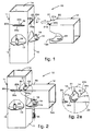
- connection and attachment fixture 10 is used to connect a first and a second element, in this case an upright 11 and a cross-piece 12 of the frame of a table. It comes within the scope of the present invention that the fixture 10 can be applied for any elements of modular structures that have to be connected together at an angle.
- the upright 11 and the cross-piece 12 are advantageously metal tubular elements that have respective axial compartments 11a and 12a and, in this case, have a substantially square cross section, equal to each other.
- the tubular elements can have any shape section, for example circular, polygonal, oval or otherwise, and any thickness and/or size.
- the upright 11 comprises in this case two attachment fins 13 made in a piece by sectioning from its respective outer surfaces 15 and 16, in this case adjacent. To be more exact, the sectioning is performed in this case on three sides of the fin 13, while one side, in this case, the lower one, is only weakened along a line 26 which has micro-joints, for example obtained by laser cutting, in order to facilitate the subsequent opening of the fin 13 by the final user too.
- Each of the attachment fins 13 is folded towards the outside so as to define a base arranged on a plane substantially perpendicular to the respective outer surface 15, 16; during the assembly of the two elements 11 and 12, the fin 13 is inserted inside the axial compartment 12a of the cross-piece 12, substantially adhering to its inner wall, in order to determine the attachment of the upright 11 and the cross-piece 12 as will be explained hereafter.
- Each fin 13 also has a through hole 17 into which, in the case shown here, a threaded bushing 19 is inserted. It comes within the scope of the invention that, instead of the threaded bushing 19, a simple smooth hole is made and self-threading screws are used for the connection.
- a slit 20 is also made, arranged substantially horizontal in the figures, and including a first segment 20a with a first transverse size and a second segment 20b arranged adjacent and above the first segment 20a, having a second transverse size smaller than the first.
- the second segment 20b is arranged below the first segment 20a, or that there is a second segment above and a second segment below the first segment 20a, in order to facilitate the passage of possible thicker parts deriving from the welding and present in the tubular element 12 at the moment of coupling.
- the two segments 20a and 20b define two lateral abutment shoulders 20c.
- the cross-piece 12 comprises, at one end 22, a positioning extension consisting of a tongue 21 protruding and made in one piece therewith, able to be inserted inside the respective slit 20, in order to reciprocally position the upright 11 and the cross-piece 12 and allow the centered coupling thereof.
- the tongue 21 is shaped so as to have a front segment 21a with a transverse size mating with that of the first segment 20a of the slit 20, and a rear segment 21b with a transverse size mating with that of the second segment 20b of the slit 20. This conformation defines two stop recesses 21c between the two segments 21a and 21b.
- the shaped tongue 21 is inserted inside the slit 20 making its front segment 21a pass through the first segment 20a, and is then displaced vertically, so that its rear segment 21b engages with the second segment 20b, and the stop recesses 21c cooperate with the abutment shoulders 20c (fig. 2a), in order to prevent the tongue 21 from accidentally slipping out of the respective slit 20.
- the cross-piece 12 also comprises, near the end 22 but on the opposite side with respect to the tongue 21, a slot or hole 23 able during use to be arranged below and aligned with the through hole 17 of the respective attachment fin 13; through such slot 23 a screw 25 can be inserted, or a bolt, which, screwed to the threaded bushing 19, or self-threading into a hole, determines the attachment of the upright 11 and cross-piece 12.
- connection and attachment fixture 10 provides the following steps. First the attachment fins 13 are sectioned, with the desired profile, from the respective outer surfaces 15 and 16, by means of known cutting techniques, such as for example laser rays, shearing, or otherwise, but leaving at least said segment 26 of the perimeter of such fins 13 micro-joined to the respective outer surfaces 15 and 16.
- the presence of the micro-joined segment 26, in a third step (fig. 5), allows to bend the fin 13, thus cut, towards the outside, so that the latter, already equipped with the hole 17 and/or the bushing 19, can be arranged on a plane substantially perpendicular to the respective outer surface 15, 16.
- the bending of the fins 13 can also be done by the final user, so that during the steps to transport and store the tubular element 11 in the dismantled condition there are no protruding parts that increase the bulk and can cause cuts to the packaging, damage to adjacent pieces and small accidents.
- the slits 20 are made, for example using the same technique as that used to section the fin 13.
- the tongue 21 is made, by means of a shaped profiling of the end 22 of the cross-piece 12, for example achieved by means of the technique of cutting with laser ray.
- the slot 23 is made in a suitable way.
- attachment fins 13 may be provided made in a piece on every outer surface of the upright 11, or various attachment fins 13 may be provided arranged at various heights on every outer surface of the upright 11, in order to couple several cross-pieces positioned above the same upright.
- attachment fin 13 is made in a piece on the cross-piece 12, while the tongue 21 is made on the upright 11. In the event that the cross-piece 12 is not tubular, it comes within the scope of the invention to make thereon a seating for the attachment fin 13.
Landscapes
- Engineering & Computer Science (AREA)
- General Engineering & Computer Science (AREA)
- Mechanical Engineering (AREA)
- Mutual Connection Of Rods And Tubes (AREA)
Applications Claiming Priority (2)
| Application Number | Priority Date | Filing Date | Title |
|---|---|---|---|
| ITUD20030222 ITUD20030222A1 (it) | 2003-11-12 | 2003-11-12 | Attrezzatura di collegamento ed aggancio per elementi di una struttura componibile, e relativo procedimento di realizzazione. |
| ITUD20030222 | 2003-11-12 |
Publications (1)
| Publication Number | Publication Date |
|---|---|
| EP1530922A1 true EP1530922A1 (de) | 2005-05-18 |
Family
ID=34430828
Family Applications (1)
| Application Number | Title | Priority Date | Filing Date |
|---|---|---|---|
| EP04105690A Withdrawn EP1530922A1 (de) | 2003-11-12 | 2004-11-11 | Anschlu und Befestigungvorrichtung für Elemente einer modularen Struktur und Zugehöriges Aufbauverfahren |
Country Status (2)
| Country | Link |
|---|---|
| EP (1) | EP1530922A1 (de) |
| IT (1) | ITUD20030222A1 (de) |
Cited By (4)
| Publication number | Priority date | Publication date | Assignee | Title |
|---|---|---|---|---|
| WO2014013096A1 (es) * | 2012-07-19 | 2014-01-23 | Yudigar, S.L.U. | Soporte de expositor |
| DE112016002098B4 (de) | 2015-05-08 | 2019-06-19 | Mitsubishi Electric Corporation | Rahmenmontagekörper und Gehäuse |
| FR3095822A1 (fr) * | 2019-05-06 | 2020-11-13 | Coveris | Procédé d’assemblage par emboîtement d’une traverse et d’un montant d’une structure porteuse et structure porteuse comprenant au moins un tel assemblage par emboîtement |
| US12371901B2 (en) | 2019-12-23 | 2025-07-29 | Steelcase Inc. | Furniture system |
Citations (4)
| Publication number | Priority date | Publication date | Assignee | Title |
|---|---|---|---|---|
| AU429630B2 (de) * | 1969-04-11 | 1972-10-26 | ||
| DE2161889A1 (de) * | 1971-12-14 | 1973-06-20 | Geb Posselt Ursula Schaefer | Steck- und riegelverbindung |
| DE19920427A1 (de) | 1999-05-04 | 2000-11-30 | Ulrich Dueser | Rohrverbindung |
| US6457787B1 (en) * | 2000-11-09 | 2002-10-01 | Stanford M. Chicoyne | Frame joint system |
-
2003
- 2003-11-12 IT ITUD20030222 patent/ITUD20030222A1/it unknown
-
2004
- 2004-11-11 EP EP04105690A patent/EP1530922A1/de not_active Withdrawn
Patent Citations (4)
| Publication number | Priority date | Publication date | Assignee | Title |
|---|---|---|---|---|
| AU429630B2 (de) * | 1969-04-11 | 1972-10-26 | ||
| DE2161889A1 (de) * | 1971-12-14 | 1973-06-20 | Geb Posselt Ursula Schaefer | Steck- und riegelverbindung |
| DE19920427A1 (de) | 1999-05-04 | 2000-11-30 | Ulrich Dueser | Rohrverbindung |
| US6457787B1 (en) * | 2000-11-09 | 2002-10-01 | Stanford M. Chicoyne | Frame joint system |
Cited By (4)
| Publication number | Priority date | Publication date | Assignee | Title |
|---|---|---|---|---|
| WO2014013096A1 (es) * | 2012-07-19 | 2014-01-23 | Yudigar, S.L.U. | Soporte de expositor |
| DE112016002098B4 (de) | 2015-05-08 | 2019-06-19 | Mitsubishi Electric Corporation | Rahmenmontagekörper und Gehäuse |
| FR3095822A1 (fr) * | 2019-05-06 | 2020-11-13 | Coveris | Procédé d’assemblage par emboîtement d’une traverse et d’un montant d’une structure porteuse et structure porteuse comprenant au moins un tel assemblage par emboîtement |
| US12371901B2 (en) | 2019-12-23 | 2025-07-29 | Steelcase Inc. | Furniture system |
Also Published As
| Publication number | Publication date |
|---|---|
| ITUD20030222A1 (it) | 2005-05-13 |
Similar Documents
| Publication | Publication Date | Title |
|---|---|---|
| US4632473A (en) | Cabinet assembly | |
| JPH10309212A (ja) | 支持ポストおよび支持システム | |
| AU2005300063A1 (en) | Tool rack set fastener | |
| JP2021171624A (ja) | スライドレールアセンブリ | |
| EP1530922A1 (de) | Anschlu und Befestigungvorrichtung für Elemente einer modularen Struktur und Zugehöriges Aufbauverfahren | |
| KR20180087650A (ko) | 가구용 골격 조립구조 | |
| US20160262541A1 (en) | Channel tube and tube nut framing apparatus | |
| JP4414743B2 (ja) | テーブル | |
| KR102015949B1 (ko) | 프레임 유닛 및 탁자 | |
| JP2008301972A (ja) | 棚装置における付属部材の支持装置 | |
| JP2005087625A (ja) | 机 | |
| JP4470675B2 (ja) | 部材の連結構造 | |
| US6848368B2 (en) | Stand device | |
| KR101848083B1 (ko) | 중간대를 구비한 중공문짝 | |
| JPH08238131A (ja) | 実験台等のフレーム装置 | |
| KR200495401Y1 (ko) | 진열대 설치용 조립식 경량랙 | |
| US20060231703A1 (en) | Bracket | |
| KR101614834B1 (ko) | 장식 가구용 접이식 패널 | |
| KR200486773Y1 (ko) | 조립식 진열장 조립체 | |
| KR200368904Y1 (ko) | 칸막이용 포스트 | |
| JP4460280B2 (ja) | 書籍陳列棚 | |
| EP1612433A1 (de) | Anschlussverbindung für ein Möbelgestell | |
| JP5888934B2 (ja) | 机 | |
| JPS5942929Y2 (ja) | ユニツト引出し | |
| KR200234401Y1 (ko) | 공구걸이대 및 작업대 기능이 구비된 칸막이 |
Legal Events
| Date | Code | Title | Description |
|---|---|---|---|
| PUAI | Public reference made under article 153(3) epc to a published international application that has entered the european phase |
Free format text: ORIGINAL CODE: 0009012 |
|
| AK | Designated contracting states |
Kind code of ref document: A1 Designated state(s): AT BE BG CH CY CZ DE DK EE ES FI FR GB GR HU IE IS IT LI LU MC NL PL PT RO SE SI SK TR |
|
| AX | Request for extension of the european patent |
Extension state: AL HR LT LV MK YU |
|
| AKX | Designation fees paid | ||
| REG | Reference to a national code |
Ref country code: DE Ref legal event code: 8566 |
|
| STAA | Information on the status of an ep patent application or granted ep patent |
Free format text: STATUS: THE APPLICATION IS DEEMED TO BE WITHDRAWN |
|
| 18D | Application deemed to be withdrawn |
Effective date: 20051119 |