EP1530897B1 - Futterraufe - Google Patents
Futterraufe Download PDFInfo
- Publication number
- EP1530897B1 EP1530897B1 EP04292686A EP04292686A EP1530897B1 EP 1530897 B1 EP1530897 B1 EP 1530897B1 EP 04292686 A EP04292686 A EP 04292686A EP 04292686 A EP04292686 A EP 04292686A EP 1530897 B1 EP1530897 B1 EP 1530897B1
- Authority
- EP
- European Patent Office
- Prior art keywords
- frame
- rack
- fixed
- uprights
- grid
- Prior art date
- Legal status (The legal status is an assumption and is not a legal conclusion. Google has not performed a legal analysis and makes no representation as to the accuracy of the status listed.)
- Expired - Lifetime
Links
- 241001465754 Metazoa Species 0.000 title claims abstract description 29
- 238000000034 method Methods 0.000 claims abstract description 4
- 230000004888 barrier function Effects 0.000 claims description 9
- 230000003014 reinforcing effect Effects 0.000 claims description 4
- 230000000694 effects Effects 0.000 claims description 3
- 239000002184 metal Substances 0.000 claims description 3
- 230000000903 blocking effect Effects 0.000 abstract description 3
- 244000144972 livestock Species 0.000 abstract 1
- 241000283690 Bos taurus Species 0.000 description 5
- 239000004459 forage Substances 0.000 description 3
- 210000003128 head Anatomy 0.000 description 2
- 238000003466 welding Methods 0.000 description 2
- 230000000295 complement effect Effects 0.000 description 1
- 210000005069 ears Anatomy 0.000 description 1
- 235000013305 food Nutrition 0.000 description 1
- 238000005246 galvanizing Methods 0.000 description 1
- 210000001331 nose Anatomy 0.000 description 1
- 239000003973 paint Substances 0.000 description 1
- 230000002787 reinforcement Effects 0.000 description 1
- 239000007787 solid Substances 0.000 description 1
Images


Classifications
-
- A—HUMAN NECESSITIES
- A01—AGRICULTURE; FORESTRY; ANIMAL HUSBANDRY; HUNTING; TRAPPING; FISHING
- A01K—ANIMAL HUSBANDRY; AVICULTURE; APICULTURE; PISCICULTURE; FISHING; REARING OR BREEDING ANIMALS, NOT OTHERWISE PROVIDED FOR; NEW BREEDS OF ANIMALS
- A01K1/00—Housing animals; Equipment therefor
- A01K1/10—Feed racks
-
- A—HUMAN NECESSITIES
- A01—AGRICULTURE; FORESTRY; ANIMAL HUSBANDRY; HUNTING; TRAPPING; FISHING
- A01K—ANIMAL HUSBANDRY; AVICULTURE; APICULTURE; PISCICULTURE; FISHING; REARING OR BREEDING ANIMALS, NOT OTHERWISE PROVIDED FOR; NEW BREEDS OF ANIMALS
- A01K1/00—Housing animals; Equipment therefor
- A01K1/0005—Stable partitions
- A01K1/0017—Gates, doors
Definitions
- the present invention relates to a rack for receiving the fodder constituting part of the feed of farm animals, in particular cattle.
- Some racks known in the prior art are round or square, and can accommodate one or two round boots maximum. The farmer places them on the ground in free stabling, fixing them on the ground or not. These racks have the disadvantage of forcing the breeder to enter the stabling to recharge the racks forage, which can affect its safety. Another disadvantage of these racks is that they take up space on the ground and leave less room for the movement of animals.
- the present invention aims to overcome some disadvantages of the prior art by providing a rack that can contain several bales of forage, which can be reloaded without risk to the farmer from outside the stall and without handling boots , which can accommodate either round or square boots, which does not interfere with the movement of animals in the stabling and encroaches little on their space, which is easy to transport and install and which can be galvanized.
- a rack intended to receive at least one bunch of fodder for feeding farm animals, characterized in that it consists of a frame and at least two amounts, removably attached to each side of the plane of symmetry of said frame, uprights on which is fixed detachably respectively a surface and a flat grid, the planes of symmetry of the surface and the grid being secant between them, the surface and the grid being intended to support the (the) boot (s) of fodder, and the animals feeding through the spacing provided between the bars of the grid, in that the frame is removably attached between two posts, so as to be pivotable around one of the posts to provide a barrier to block the animals inside the farm building or to make them leave the building when the farmer decides.
- the various elements constituting the rack are galvanizable.
- the frame is substantially rectangular and consists of two horizontal uprights and two vertical uprights, in that the animal side, the uprights consist of at least two bent tubular bars substantially in the form of an ear or " C "inverted, said extreme tubular bars, removably attached to the horizontal uprights of the frame, each near one of the vertical frame uprights, and in that, on the other side of the frame relative to the animals, the uprights are external uprights removably attached to the extreme tubular bars to form each with the surface and the frame a triangle.
- the space formed between the triangles formed by the outer uprights with the surface and the frame is free to allow loading from outside the rack.
- animal side at least one bent tubular bar, substantially shaped ear or "C” inverted, said (s) bar (s) tubular (s) intermediate (s), is removably attached at the horizontal jambs of the frame, between the extreme tubular bars.
- the grid is fixed to each of the extreme or intermediate tubular bars, and in that the surface is fixed both to the external uprights and to the lower horizontal upright of the frame.
- the surface is made of sheet metal and provided with a plurality of ribs designed to avoid a "suction cup” effect.
- each extreme tubular bar and each outer upright is provided with a grid for retaining the forage.
- the surface is inclined at an angle ⁇ relative to the vertical, and in that the grid is inclined at an angle ⁇ relative to the vertical.
- ⁇ is of the order of 20 ° to 40 ° and ⁇ of the order of 30 ° to 60 °.
- the rack is provided, under the frame, with a reinforcing bar.
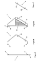
- the rack according to the invention shown in particular in Figure 1, comprises a frame (1), visible in particular in Figures 2 and 3.
- This frame (1) consists of four uprights substantially orthogonal to each other.
- the two vertical uprights of the frame are fixed, as will be seen later, between the posts (7a, 7b) located at the entrance of a farm building, the rack according to the invention replacing the barrier allowing entry and the exit of the animals.
- the frame is provided at its lower end with a tubular reinforcing bar (10) located in the same plane as the frame (1).
- This reinforcement bar is for example fixed at several points of the lower frame upright, by welding with a plurality of tubes, as shown in FIG. 2.
- the frame (1) also comprises, on each of its horizontal uprights, a plurality of plates (11) each provided with at least one hole.
- the rack according to the invention also comprises a plurality of bent tubular bars (2, 3) substantially shaped ear or "C" inverted, each contained in a plane substantially orthogonal to the plane of the frame (1).
- Two of the bent tubular bars, called extreme tubular bars (2) are fixed respectively at each end of the frame (1) of the rack, while the other bent tubular bars, called intermediate tubular bars (3), are fixed on the frame by being distributed between the end tubular bars (2), as shown in particular in Figure 2.
- the rack according to the invention comprises for example three intermediate tubular bars (3).
- each extreme or intermediate tubular bar (2, 3) is provided with each of its ends with a hook (21, 31) provided with at least one piercing.
- Each of the hooks (21, 31) is intended to suspend the extreme or intermediate tubular bar (2, 3) on the horizontal uprights of the frame, as shown in particular in FIG. 10, so that the location of each of the hooks (21, 31) corresponds to the location of a plate (11) of the frame (1).
- Each extreme or intermediate tubular bar (2, 3) is then fixed to the frame (1) by bolting the plates (11) of the frame (1) with the corresponding hooks (21, 31) of said bar.
- the extreme and intermediate tubular bars (2, 3) are all attached to the same side of the frame (1), which is the side of the rack where the animals are, and therefore the interior side of the farm building.
- Each extreme or intermediate tubular bar (2, 3) is also provided with a pair of plates (22, 32) located in the plane of said bar and disposed towards the inside of the ear, on a straight portion of the bar making an angle ( ⁇ ) determined with the plane of the frame. This angle is for example between 20 ° and 40 °, preferably equal to 30 °.
- Each of these plates (22, 32) is provided with at least one piercing.
- each of the extreme tubular bars (2) is provided with a grid (23), located in the plane of said bar, and constituted by vertical bars for example spaced from each other by 10 cm, so as to avoid that the hay falls on each side of the rack when the boots break up as the animals feed on them.
- the rack according to the invention also comprises a grid (4), shown in particular in Figures 2 and 6, contained in a plane forming an angle ( ⁇ ) determined relative to the plane of the frame, and intended to support the animal side boots .
- This angle is for example between 20 ° and 40 °, preferably equal to 30 °.
- the grid (4) of the rack is arranged parallel to the straight portions of the end and intermediate tubular bars (2, 3) provided with a pair of plates (22, 32), inside the ears, as shown in particular in Figure 11.
- the rack (4) of the rack consists of substantially parallel bars between them including the spacing is sufficient to allow the passage of a bovine muzzle, but too small to allow the passage of his head, so as to prevent animals from catching their heads.
- the spacing of the bars of the grid (4) is for example 19 cm.
- the grid (4) is provided with a plurality of pairs of plates (42) arranged under the grid whose location corresponds to the location of the pairs of plates (22, 32) of the extreme and intermediate tubular bars (2, 3 ).
- the grid (4) is fixed to each end or intermediate tubular bar (2, 3) by bolting the plates (42) of the grid (4) with the plates (22, 32) of said bars.
- the rack according to the invention also comprises two outer legs (5), substantially triangular, shown in particular in Figure 7, and contained in a plane substantially orthogonal to the plane of the frame (1).
- Each of the outer uprights (5) consists of three bars bolted to each other, one of these bars being substantially vertical, and another making an angle ( ⁇ ) determined with the vertical. This angle is for example between 30 ° and 60 °, preferably equal to 45 °.
- the third bar protrudes upwards from the triangle and is provided at its upper end with at least one piercing. This piercing (s) allows (the) fixing each of the outer uprights (5) by bolting on a plate (24) fixed at the top of each extreme tubular bar (2).
- Each of the outer uprights (5) is fixed on the opposite side to the animals, therefore the outer side of the farm building.
- Each of the outer uprights (5) is provided with a grid (53) located in the plane of said upright, consisting of vertical bars for example spaced from each other by 10 cm, so as to prevent the hay falls on each side racks when the boots break up as the animals feed on them.
- the rack according to the invention finally comprises a surface (6), shown in particular in Figure 8, contained in a plane making an angle ( ⁇ ) determined relative to the plane of the frame, and intended to support the boots on the outside.
- This angle is for example between 30 ° and 60 °, preferably equal to 45 °.
- the surface (6) is arranged parallel to the bars of the outer uprights (5) making an angle ( ⁇ ) determined relative to the plane of the frame, as shown in particular in Figure 1.
- the surface is preferably sheet metal and provided with a plurality of ribs to avoid a "suction cup" effect when the boots, which are placed on this surface (6) and on the grid (4), are slightly damp.
- the surface (6) is provided with at least three flanges on its sides which engage respectively with the lateral uprights (5) and with the lower horizontal upright of the frame (1), to which they are fastened by bolting.
- the flange of the surface (6) attaching to said frame member has a right angle allowing to bear on two sides of said amount, as shown in particular in Figure 1.
- the space formed between the triangles formed by the outer uprights (5) with the surface (6) and the frame (1) is free to allow boots to be loaded from outside the rack.
- the rack being made to support a large mass (up to about 2 tons), it is important that its structure is solid.
- the rack is therefore metallic.
- all the elements (1 to 6) constituting the rack, as well as the fastening elements of the rack on the poles (7a, 7b) of the farm building, must be strong enough to support several tons.
- the grids (23, 53) of the extreme tubular bars (2) and the outer uprights (5) are for example fixed by welding respectively to the end tubular bars (2) and to the outer uprights (5).
- the first step of the assembly ( Figure 9) is to fix the frame (1) between the posts (7a, 7b) of the farm building.
- a second step (FIG. 10)
- the intermediate tubular bars (3) are fixed to the frame (1).
- the grid (4) is fixed to the intermediate tubular bars (3).
- the end tubular bars (2) are fixed to the frame (1) and to the grid (4).
- the amount outside (5) is fixed to the end tubular bars (2).
- the surface (6) is attached to the outer uprights (5) and the frame (1).
- the farmer has several haystacks on the grill (4) and the surface (6) by inserting them from the outside of the farm. Thus, its security is perfectly ensured since it does not have to penetrate the stabling.
- the animals feed by passing their muzzle between the bars of the grid (4) of the rack.
- the rack being arranged in place of a barrier, it must be open to let the animals out and / or to curse the stabulations.
- the frame (1) of the rack is fixed so as to pivot around one of the posts (7a, 7b) and can be maintained in closed position without the animals can go out without intervention of the breeder.
- the frame (1) of the rack is symmetrical so that the breeder can choose in which direction the frame will open, that is to say around which pole it will rotate.
- the frame (1) is provided, near the lower end of each of its vertical uprights, with a substantially horizontal protruding element (12a, 12b) disposed towards the outside of the frame and reinforced by a triangular plate. (13a, 13b) serving as a square.
- a substantially vertical pin (14) is welded below each projecting member (12a, 12b).
- This lug (12) will serve as a pivot on the side of the pivot pole (7b) by being inserted into a bore made in a plate (74) substantially horizontal fixed on the pivot pole (7b), as shown in Figure 2.
- the lug on the other side of the frame is sawn.
- first plates (72, 73) each provided with a bore through which a first rod passes.
- substantially vertically removable locking means (71) This first blocking rod (71) makes it possible to retain the rack when the projecting element (12a) situated opposite the pivoting post (7b) is located between the post (7a) opposite the pivoting post (7b). and said first blocking rod (71). It suffices to remove this first locking rod (71) from the bores to release said projecting element (12a).
- the frame (1) is also provided on each of its vertical uprights, at least two bores (respectively 15a, 16a and 15b, 16b), substantially horizontal located in the plane of the frame.
- One of these holes (15a, 15b) is located at a height easily accessible by a person of average size, the other hole (16a, 16b) being located near the upper end of the corresponding vertical upright of the frame (1) .
- the highest bore (16a, 16b) is used for pivoting of the rack while the other (15a, 15b) is used to lock the rack in the closed position.
- a rod (150, 160) is fixed in each of the bores used (respectively 15a and 16b in the case of Figure 2, the pole 7b being designated as the pivot pole) by bolts, this rod (150, 160) is ending with a loop.
- Each of the loops is inserted between two plates (respectively 77a, 78a and 77b, 78b), respectively called second plates (77a, 78a) and third plates (77b, 78b), provided with a bore.
- a second and third locking rods (respectively 75 and 76) removable substantially vertical through these holes and the loop of the corresponding rods (respectively 150 and 160).
- a tensioner (8) is stretched between a point located near the upper end of the pivot post (7b) and the upper end of the vertical upright of the frame (1) opposite to the pivot post (7b), as shown in Figure 2.
- the rack can pivot about the pivot pole (7b) by being held by three pivot points.
- the assembly of the rack according to the invention is relatively simple.
- the fact that the rack is delivered in several elements makes it possible to galvanize it before assembly, which allows a longer hold than paint.
- the transport is facilitated since the different elements of the rack can be nested to obtain a smaller volume than the racks mounted, which also has the advantage of allowing the transport of several racks in one trip.
- the length of the rack is for example, but not limited to, 5 m or 6 m, which corresponds to the standard distance from the entrance of the farm buildings.
- the rack can accommodate up to 4 round boots of standard size or two rectangular boots of standard size.
- the height of the rack is for example about 2.5 m, thus creating a real barrier for cattle.
- the thickness of the rack is for example 2.5 m, a portion being located outside the building which allows to encroach on the space of the animals. It may be provided to install a roof above the rack to protect the fodder against the weather.
- the frame (1) can be fixed to the posts (7a, 7b) of the farm building by any other fastening means sufficiently strong to allow the opening of the rack as a barrier by pivoting about a vertical axis. Therefore, the present embodiments should be considered by way of illustration, but may be modified within the scope defined by the scope of the appended claims, and the invention should not be limited to the details given above.
Landscapes
- Life Sciences & Earth Sciences (AREA)
- Environmental Sciences (AREA)
- Zoology (AREA)
- Animal Husbandry (AREA)
- Biodiversity & Conservation Biology (AREA)
- Assembled Shelves (AREA)
- Greenhouses (AREA)
- Feed For Specific Animals (AREA)
- Valve-Gear Or Valve Arrangements (AREA)
- Valve Device For Special Equipments (AREA)
- Packaging Of Annular Or Rod-Shaped Articles, Wearing Apparel, Cassettes, Or The Like (AREA)
- Housing For Livestock And Birds (AREA)
- Saccharide Compounds (AREA)
Claims (14)
- Krippenrost für wenigstens eine Portion Futter für das Füttern von Farmtieren, dadurch gekennzeichnet, dass dieser aus einem Rahmen (1) und wenigstens zwei Stäben (2, 5) besteht, demontierbar befestigt auf jeder Seite der Symmetrieebene des so genannten Rahmens (1), wobei an den Stäben (2, 5) eine ebene Fläche (6) bzw. ein ebener Rost (4) demontierbar befestigt ist, die Symmetrieebenen der Fläche (6) und des Rostes (4) sich schneiden, die Fläche (6) und der Rost (4) dazu bestimmt sind, die Portion (Portionen) des Futters zu halten, die Tiere sich ihre Nahrung aus dem Zwischenraum zwischen den Stäben des Rostes (4) entnehmen, der Rahmen (1) demontierbar zwischen zwei Stützpfeilern (7a, 7b) befestigt ist, so dass dieser sich um einen der Pfeiler (7b) bewegen kann, um als Hindernis zu dienen, welches die Tiere im Inneren des Farmgebäudes festhält oder das diesen den Ausgang aus dem Gebäude erlaubt, wann immer der Tierzüchter es bestimmt.
- Krippenrost nach Anspruch 1, dadurch gekennzeichnet, dass die verschiedenen Elemente, aus denen der Krippenrost besteht, galvanisierbar sind.
- Krippenrost nach Anspruch 1 oder 2, dadurch gekennzeichnet, dass der Rahmen (1) annähernd rechteckig ist und aus zwei horizontalen Stäben und zwei vertikalen Stäben besteht, und dadurch, dass auf der Seite der Tiere die Stäbe aus wenigstens zwei rohrförmigen Stangen bestehen, die annähernd in Kreisform oder in umgekehrter C-Form gebogen sind, die so genannten äußeren rohrförmigen Stangen (2) demontierbar befestigt sind an den vertikalen Stäben des Rahmens (1), jede in der Nähe eines der vertikalen Stäbe des Rahmens (1), und dadurch, dass auf der anderen Seite des Rahmens, bezogen auf die Tiere, die Stäbe, die so genannten äußeren Stäbe (5), demontierbar befestigt sind an den rohrförmigen äußeren Stangen (2), so dass jede mit der Fläche (6) und dem Rahmen (1) ein Dreieck bildet.
- Krippenrost nach Anspruch 3, dadurch gekennzeichnet, dass der Zwischenraum zwischen den Dreiecken, gebildet aus den äußeren Stäben (5) mit der Fläche (6) und dem Rahmen (1), frei ist, um das Auffüllen des Krippenrostes von außen zu ermöglichen.
- Krippenrost nach Anspruch 3 oder 4, dadurch gekennzeichnet, dass auf der Seite der Tiere wenigstens eine rohrförmige in Kreisform oder umgekehrter C-Form gebogene Stange, die so genannte/n rohrförmige/n Zwischenstange/n (3), demontierbar befestigt ist an den horizontalen Stäben des Rahmens (1), zwischen den äußeren rohrförmigen Stangen (2).
- Krippenrost nach Anspruch 4 oder 5, dadurch gekennzeichnet, dass der Rost (4) an jeder der rohrförmigen äußeren Stangen (2) oder den dazwischen liegenden Stangen (3) befestigt ist, und dadurch, dass die Fläche (6) gleichzeitig an den äußeren Stäben (5) und an dem inneren horizontalen Stab des Rahmens (1) befestigt ist.
- Krippenrost nach einem der Ansprüche 1 bis 6, dadurch gekennzeichnet, dass die Fläche (6) aus Blech ist, verstärkt durch eine Vielzahl von Rippen, welche dazu bestimmt ist, um den so genannten Saugnapfeffekt zu verhindern.
- Krippenrost nach einem der Ansprüche 3 bis 7, dadurch gekennzeichnet, dass jede rohrförmige äußere Stange (2) und jeder äußere Stab (5) vorgesehen ist mit einem Rost (23, 53), welcher das Zurückhalten des Futters ermöglicht.
- Krippenrost nach einem der Ansprüche 1 bis 8, dadurch gekennzeichnet, dass die Fläche (6) geneigt ist bis zu einem Winkel β in Bezug auf die Senkrechte, und dadurch, dass der Rost (4) geneigt ist bis zu einem Winkel α in Bezug auf die Senkrechte.
- Krippenrost nach Anspruch 9, dadurch gekennzeichnet, dass α die Größenordnung von 20° bis 40° hat und β die Größenordnung von 30° bis 60°.
- Krippenrost nach einem der Ansprüche 1 bis 10, dadurch gekennzeichnet, dass der Krippenrost unter dem Rahmen (1) durch eine Verstärkungsstange (10) verstärkt ist.
- Krippenrost nach einer der Ansprüche 1 bis 11, dadurch gekennzeichnet, dass der Rahmen (1) mit drei Pivotierungspunkten um den Pfeiler versehen ist , um den der Krippenrost pivotieren wird, wobei der Pfeiler als Pivotierungspfeiler (7b) bezeichnet wird;- der erste Pivotierungspunkt gebildet wird aus einem annähernd vertikal angeordneten Vorsprung (14), gelegen in der Nähe der inneren Ecke des Rahmens (1) in der Nähe des Pivotierungspfeilers (7b), welcher in ein Loch in einer annähernd horizontal angeordneten Platte (74) eingeschoben ist, die an dem Pivotierungspfeiler (7b) befestigt ist,- der zweite Pivotierungspunkt gebildet wird aus einem ersten Stab (76), der annähernd vertikal in zwei Löcher bzw. in zwei Platten (77b, 78b), die annähernd horizontal und eine über der anderen gelegen angeordnet sind, eingeschoben wird, sowie in einer Schleife eines zweiten Stabes (160) annähernd horizontal befestigt wird nahe an der oberen Ecke des Rahmens (1) in der Nähe des Pivotierungspfeilers (7b), und- der dritte Pivotierungspunkt, der gebildet wird aus dem Befestigungspunkt einer der Extremitäten eines Spanners (8) in der Nähe der oberen Extremität des Pivotierungspfeilers (7b), während die andere Extremität des so genannten Spanners befestigt ist in der Nähe der oberen Ecke des Rahmens (1) gegenüber dem Pivotierungspfeiler (7b).
- Krippenrost nach einem der Ansprüche 1 bis 12, dadurch gekennzeichnet, dass der Rahmen (1) mit zwei Punkten zur Feststellung des Krippenrostes versehen ist:- der erste Feststellungspunkt wird gebildet aus einem Vorsprungelement (12a), gelegen in der Nähe der unteren Ecke des Rahmens (1) gegenüber dem Pivotierungspfeiler (7b), annähernd vertikal und unbeweglich eingeschoben zwischen zwei ersten Platten (72, 73), jede vorgesehen mit einem Feststellungsstab (71), wobei dieser Blockierungsstab (71) den Vorsprung (12a) zwischen dem Pfeiler (7a), entgegengesetzt dem Pivotierungspfeiler (7b), und dem so genannten Feststellungsstab (71) festhält,- der zweite Feststellungspunkt wird gebildet aus einem annähernd vertikalen und unbeweglichen zweiten Stab (76), welcher eingeschoben ist in zwei Löcher der Platten (77a, 78a), die annähernd horizontal und eine über der anderen gelegen angeordnet sind, sowie in die Schleife eines zweiten Stabes (150) annähernd horizontal, auf der Seite des Rahmens (1) in der Nähe des Pivotierungspfeilers (7b) gelegen, befestigt wird.
- Verfahren zur Montage des Krippenrostes nach einem der Ansprüche 1 bis 13, dadurch gekennzeichnet, dass dieses folgende Etappen umfasst:- Befestigung des Rahmens (1) zwischen den Pfeilern (7a, 7b) des Farmgebäudes,- Befestigung der rohrförmigen Zwischenstangen (3) an dem Rahmen (1),- Befestigung des Rostes (4) an den rohrförmigen Zwischenstangen (3),- Befestigung der äußeren rohrförmigen Stangen (2) an dem Rahmen (1) und an dem Rost (4),- Befestigung des äußeren Stabes (5) an den außen liegenden rohrförmigen Stangen (2), und- Befestigung der Fläche (6) an den äußeren Stäben (5) und an dem Rahmen (1).
Applications Claiming Priority (2)
| Application Number | Priority Date | Filing Date | Title |
|---|---|---|---|
| FR0313319 | 2003-11-14 | ||
| FR0313319A FR2862186B1 (fr) | 2003-11-14 | 2003-11-14 | Ratelier |
Publications (3)
| Publication Number | Publication Date |
|---|---|
| EP1530897A2 EP1530897A2 (de) | 2005-05-18 |
| EP1530897A3 EP1530897A3 (de) | 2005-06-15 |
| EP1530897B1 true EP1530897B1 (de) | 2006-09-13 |
Family
ID=34429987
Family Applications (1)
| Application Number | Title | Priority Date | Filing Date |
|---|---|---|---|
| EP04292686A Expired - Lifetime EP1530897B1 (de) | 2003-11-14 | 2004-11-12 | Futterraufe |
Country Status (4)
| Country | Link |
|---|---|
| EP (1) | EP1530897B1 (de) |
| AT (1) | ATE339096T1 (de) |
| DE (1) | DE602004002365D1 (de) |
| FR (1) | FR2862186B1 (de) |
Families Citing this family (1)
| Publication number | Priority date | Publication date | Assignee | Title |
|---|---|---|---|---|
| CN113974893B (zh) * | 2021-10-25 | 2022-08-30 | 江苏美迪森生物医药有限公司 | 一种小鼠实验用约束装置 |
Family Cites Families (5)
| Publication number | Priority date | Publication date | Assignee | Title |
|---|---|---|---|---|
| NL8501662A (nl) * | 1985-06-10 | 1987-01-02 | Nedap Nv | Voederstation voor vee. |
| FR2628288A1 (fr) * | 1988-03-11 | 1989-09-15 | Thebault Ets Robert | Barriere de separation pour cage d'engraissement d'animaux |
| GB0025184D0 (en) * | 2000-10-13 | 2000-11-29 | Allen Peter W | Apparatus for supplying animal feed |
| US6691642B2 (en) * | 2001-06-25 | 2004-02-17 | Meredith S. Dollahan | Feed trough |
| US6601536B2 (en) * | 2001-08-10 | 2003-08-05 | Dale R. Sprik | Livestock feeder |
-
2003
- 2003-11-14 FR FR0313319A patent/FR2862186B1/fr not_active Expired - Lifetime
-
2004
- 2004-11-12 AT AT04292686T patent/ATE339096T1/de not_active IP Right Cessation
- 2004-11-12 EP EP04292686A patent/EP1530897B1/de not_active Expired - Lifetime
- 2004-11-12 DE DE602004002365T patent/DE602004002365D1/de not_active Expired - Lifetime
Also Published As
| Publication number | Publication date |
|---|---|
| ATE339096T1 (de) | 2006-10-15 |
| FR2862186A1 (fr) | 2005-05-20 |
| DE602004002365D1 (de) | 2006-10-26 |
| EP1530897A2 (de) | 2005-05-18 |
| FR2862186B1 (fr) | 2006-03-10 |
| EP1530897A3 (de) | 2005-06-15 |
Similar Documents
| Publication | Publication Date | Title |
|---|---|---|
| US8061076B2 (en) | Portable large animal trap and method | |
| CA1266698A (fr) | Stand d'observation | |
| FR2550918A1 (fr) | Systeme de nasse a crustaces en forme de tronc de pyramide a bases carrees, tres pechant, facile a transporter et a stocker | |
| EP1530897B1 (de) | Futterraufe | |
| EP0681783A1 (de) | Käfig zum Züchten von Schalentieren, insbesondere von Austern | |
| FR3026275A1 (fr) | Nourrisseur a regulation amelioree de la distribution de nourriture | |
| US9345229B2 (en) | Livestock feeding rack | |
| EP0162759B1 (de) | Vorrichtung zur Sicherung von grossen Futterballen auf Fahrzeugen | |
| EP2962560B1 (de) | Raubschutzvorrichtung für fischzuchtbecken | |
| FR3007939A1 (fr) | Ratelier pour equides | |
| KR200466135Y1 (ko) | 축사용 건초 급이장치 | |
| JP3254211U (ja) | 捕獲装置 | |
| FR2955456A1 (fr) | Dispositif et procede de capture d'animaux, notamment d'oiseaux. | |
| FR2611429A1 (fr) | Perfectionnement des installations de traite | |
| FR2973986A1 (fr) | Logement collectif pour le gavage de palmipedes | |
| FR2686773A1 (fr) | Stalle d'alimentation rabattable. | |
| FR2811512A1 (fr) | Stalle de refectoire pour betail | |
| FR2979799A1 (fr) | Barriere du type cornadis suedois | |
| FR2867215A3 (fr) | Cloture pour piscine | |
| FR2689368A1 (fr) | Perfectionnement aux rateliers d'alimentation. | |
| FR2890530A1 (fr) | Dispositif d'approvisionnement en fourrage pour animal domestique | |
| FR2589322A1 (fr) | Cage de contention basculante pour renverser les animaux | |
| FR2848384A1 (fr) | Piege a animaux, pliable a plat | |
| FR2964996A1 (fr) | Garde-corps positionnable sur une construction et dispositif de securisation d'une construction du type comprenant au moins deux garde-corps du type precite | |
| FR2613584A1 (fr) | Boite a fauves tombante |
Legal Events
| Date | Code | Title | Description |
|---|---|---|---|
| PUAI | Public reference made under article 153(3) epc to a published international application that has entered the european phase |
Free format text: ORIGINAL CODE: 0009012 |
|
| PUAL | Search report despatched |
Free format text: ORIGINAL CODE: 0009013 |
|
| AK | Designated contracting states |
Kind code of ref document: A2 Designated state(s): AT BE BG CH CY CZ DE DK EE ES FI FR GB GR HU IE IS IT LI LU MC NL PL PT RO SE SI SK TR |
|
| AX | Request for extension of the european patent |
Extension state: AL HR LT LV MK YU |
|
| AK | Designated contracting states |
Kind code of ref document: A3 Designated state(s): AT BE BG CH CY CZ DE DK EE ES FI FR GB GR HU IE IS IT LI LU MC NL PL PT RO SE SI SK TR |
|
| AX | Request for extension of the european patent |
Extension state: AL HR LT LV MK YU |
|
| 17P | Request for examination filed |
Effective date: 20051020 |
|
| AKX | Designation fees paid |
Designated state(s): AT BE BG CH CY CZ DE DK EE ES FI FR GB GR HU IE IS IT LI LU MC NL PL PT RO SE SI SK TR |
|
| GRAP | Despatch of communication of intention to grant a patent |
Free format text: ORIGINAL CODE: EPIDOSNIGR1 |
|
| GRAS | Grant fee paid |
Free format text: ORIGINAL CODE: EPIDOSNIGR3 |
|
| GRAA | (expected) grant |
Free format text: ORIGINAL CODE: 0009210 |
|
| AK | Designated contracting states |
Kind code of ref document: B1 Designated state(s): AT BE BG CH CY CZ DE DK EE ES FI FR GB GR HU IE IS IT LI LU MC NL PL PT RO SE SI SK TR |
|
| PG25 | Lapsed in a contracting state [announced via postgrant information from national office to epo] |
Ref country code: IT Free format text: LAPSE BECAUSE OF FAILURE TO SUBMIT A TRANSLATION OF THE DESCRIPTION OR TO PAY THE FEE WITHIN THE PRESCRIBED TIME-LIMIT;WARNING: LAPSES OF ITALIAN PATENTS WITH EFFECTIVE DATE BEFORE 2007 MAY HAVE OCCURRED AT ANY TIME BEFORE 2007. THE CORRECT EFFECTIVE DATE MAY BE DIFFERENT FROM THE ONE RECORDED. Effective date: 20060913 Ref country code: FI Free format text: LAPSE BECAUSE OF FAILURE TO SUBMIT A TRANSLATION OF THE DESCRIPTION OR TO PAY THE FEE WITHIN THE PRESCRIBED TIME-LIMIT Effective date: 20060913 Ref country code: SI Free format text: LAPSE BECAUSE OF FAILURE TO SUBMIT A TRANSLATION OF THE DESCRIPTION OR TO PAY THE FEE WITHIN THE PRESCRIBED TIME-LIMIT Effective date: 20060913 Ref country code: AT Free format text: LAPSE BECAUSE OF FAILURE TO SUBMIT A TRANSLATION OF THE DESCRIPTION OR TO PAY THE FEE WITHIN THE PRESCRIBED TIME-LIMIT Effective date: 20060913 Ref country code: CZ Free format text: LAPSE BECAUSE OF FAILURE TO SUBMIT A TRANSLATION OF THE DESCRIPTION OR TO PAY THE FEE WITHIN THE PRESCRIBED TIME-LIMIT Effective date: 20060913 Ref country code: SK Free format text: LAPSE BECAUSE OF FAILURE TO SUBMIT A TRANSLATION OF THE DESCRIPTION OR TO PAY THE FEE WITHIN THE PRESCRIBED TIME-LIMIT Effective date: 20060913 Ref country code: NL Free format text: LAPSE BECAUSE OF FAILURE TO SUBMIT A TRANSLATION OF THE DESCRIPTION OR TO PAY THE FEE WITHIN THE PRESCRIBED TIME-LIMIT Effective date: 20060913 Ref country code: GB Free format text: LAPSE BECAUSE OF FAILURE TO SUBMIT A TRANSLATION OF THE DESCRIPTION OR TO PAY THE FEE WITHIN THE PRESCRIBED TIME-LIMIT Effective date: 20060913 Ref country code: PL Free format text: LAPSE BECAUSE OF FAILURE TO SUBMIT A TRANSLATION OF THE DESCRIPTION OR TO PAY THE FEE WITHIN THE PRESCRIBED TIME-LIMIT Effective date: 20060913 Ref country code: RO Free format text: LAPSE BECAUSE OF FAILURE TO SUBMIT A TRANSLATION OF THE DESCRIPTION OR TO PAY THE FEE WITHIN THE PRESCRIBED TIME-LIMIT Effective date: 20060913 Ref country code: IE Free format text: LAPSE BECAUSE OF FAILURE TO SUBMIT A TRANSLATION OF THE DESCRIPTION OR TO PAY THE FEE WITHIN THE PRESCRIBED TIME-LIMIT Effective date: 20060913 |
|
| REG | Reference to a national code |
Ref country code: GB Ref legal event code: FG4D Free format text: NOT ENGLISH |
|
| REG | Reference to a national code |
Ref country code: CH Ref legal event code: EP |
|
| REG | Reference to a national code |
Ref country code: IE Ref legal event code: FG4D Free format text: LANGUAGE OF EP DOCUMENT: FRENCH |
|
| REF | Corresponds to: |
Ref document number: 602004002365 Country of ref document: DE Date of ref document: 20061026 Kind code of ref document: P |
|
| PG25 | Lapsed in a contracting state [announced via postgrant information from national office to epo] |
Ref country code: BE Free format text: LAPSE BECAUSE OF NON-PAYMENT OF DUE FEES Effective date: 20061130 Ref country code: MC Free format text: LAPSE BECAUSE OF NON-PAYMENT OF DUE FEES Effective date: 20061130 |
|
| PG25 | Lapsed in a contracting state [announced via postgrant information from national office to epo] |
Ref country code: SE Free format text: LAPSE BECAUSE OF FAILURE TO SUBMIT A TRANSLATION OF THE DESCRIPTION OR TO PAY THE FEE WITHIN THE PRESCRIBED TIME-LIMIT Effective date: 20061213 Ref country code: DK Free format text: LAPSE BECAUSE OF FAILURE TO SUBMIT A TRANSLATION OF THE DESCRIPTION OR TO PAY THE FEE WITHIN THE PRESCRIBED TIME-LIMIT Effective date: 20061213 Ref country code: BG Free format text: LAPSE BECAUSE OF FAILURE TO SUBMIT A TRANSLATION OF THE DESCRIPTION OR TO PAY THE FEE WITHIN THE PRESCRIBED TIME-LIMIT Effective date: 20061213 |
|
| PG25 | Lapsed in a contracting state [announced via postgrant information from national office to epo] |
Ref country code: DE Free format text: LAPSE BECAUSE OF FAILURE TO SUBMIT A TRANSLATION OF THE DESCRIPTION OR TO PAY THE FEE WITHIN THE PRESCRIBED TIME-LIMIT Effective date: 20061214 |
|
| PG25 | Lapsed in a contracting state [announced via postgrant information from national office to epo] |
Ref country code: ES Free format text: LAPSE BECAUSE OF FAILURE TO SUBMIT A TRANSLATION OF THE DESCRIPTION OR TO PAY THE FEE WITHIN THE PRESCRIBED TIME-LIMIT Effective date: 20061224 |
|
| PG25 | Lapsed in a contracting state [announced via postgrant information from national office to epo] |
Ref country code: IS Free format text: LAPSE BECAUSE OF FAILURE TO SUBMIT A TRANSLATION OF THE DESCRIPTION OR TO PAY THE FEE WITHIN THE PRESCRIBED TIME-LIMIT Effective date: 20070113 |
|
| PG25 | Lapsed in a contracting state [announced via postgrant information from national office to epo] |
Ref country code: PT Free format text: LAPSE BECAUSE OF FAILURE TO SUBMIT A TRANSLATION OF THE DESCRIPTION OR TO PAY THE FEE WITHIN THE PRESCRIBED TIME-LIMIT Effective date: 20070226 |
|
| NLV1 | Nl: lapsed or annulled due to failure to fulfill the requirements of art. 29p and 29m of the patents act | ||
| GBV | Gb: ep patent (uk) treated as always having been void in accordance with gb section 77(7)/1977 [no translation filed] |
Effective date: 20060913 |
|
| REG | Reference to a national code |
Ref country code: IE Ref legal event code: FD4D |
|
| PLBE | No opposition filed within time limit |
Free format text: ORIGINAL CODE: 0009261 |
|
| STAA | Information on the status of an ep patent application or granted ep patent |
Free format text: STATUS: NO OPPOSITION FILED WITHIN TIME LIMIT |
|
| REG | Reference to a national code |
Ref country code: FR Ref legal event code: ST Effective date: 20070731 |
|
| 26N | No opposition filed |
Effective date: 20070614 |
|
| BERE | Be: lapsed |
Owner name: DESSOLIERE, THIERRY Effective date: 20061130 |
|
| PG25 | Lapsed in a contracting state [announced via postgrant information from national office to epo] |
Ref country code: GR Free format text: LAPSE BECAUSE OF FAILURE TO SUBMIT A TRANSLATION OF THE DESCRIPTION OR TO PAY THE FEE WITHIN THE PRESCRIBED TIME-LIMIT Effective date: 20061214 Ref country code: FR Free format text: LAPSE BECAUSE OF NON-PAYMENT OF DUE FEES Effective date: 20061130 |
|
| PG25 | Lapsed in a contracting state [announced via postgrant information from national office to epo] |
Ref country code: EE Free format text: LAPSE BECAUSE OF FAILURE TO SUBMIT A TRANSLATION OF THE DESCRIPTION OR TO PAY THE FEE WITHIN THE PRESCRIBED TIME-LIMIT Effective date: 20060913 |
|
| PG25 | Lapsed in a contracting state [announced via postgrant information from national office to epo] |
Ref country code: HU Free format text: LAPSE BECAUSE OF FAILURE TO SUBMIT A TRANSLATION OF THE DESCRIPTION OR TO PAY THE FEE WITHIN THE PRESCRIBED TIME-LIMIT Effective date: 20070314 Ref country code: LU Free format text: LAPSE BECAUSE OF NON-PAYMENT OF DUE FEES Effective date: 20061112 Ref country code: TR Free format text: LAPSE BECAUSE OF FAILURE TO SUBMIT A TRANSLATION OF THE DESCRIPTION OR TO PAY THE FEE WITHIN THE PRESCRIBED TIME-LIMIT Effective date: 20060913 |
|
| PG25 | Lapsed in a contracting state [announced via postgrant information from national office to epo] |
Ref country code: CY Free format text: LAPSE BECAUSE OF FAILURE TO SUBMIT A TRANSLATION OF THE DESCRIPTION OR TO PAY THE FEE WITHIN THE PRESCRIBED TIME-LIMIT Effective date: 20060913 |
|
| REG | Reference to a national code |
Ref country code: CH Ref legal event code: PL |
|
| PG25 | Lapsed in a contracting state [announced via postgrant information from national office to epo] |
Ref country code: LI Free format text: LAPSE BECAUSE OF NON-PAYMENT OF DUE FEES Effective date: 20081130 Ref country code: CH Free format text: LAPSE BECAUSE OF NON-PAYMENT OF DUE FEES Effective date: 20081130 |