EP1530717B1 - Zwangsbelüftete messeinrichtung zur erfassung lufttechnischer parameter - Google Patents
Zwangsbelüftete messeinrichtung zur erfassung lufttechnischer parameter Download PDFInfo
- Publication number
- EP1530717B1 EP1530717B1 EP03787720A EP03787720A EP1530717B1 EP 1530717 B1 EP1530717 B1 EP 1530717B1 EP 03787720 A EP03787720 A EP 03787720A EP 03787720 A EP03787720 A EP 03787720A EP 1530717 B1 EP1530717 B1 EP 1530717B1
- Authority
- EP
- European Patent Office
- Prior art keywords
- air
- sensors
- ventilated
- automobiles
- housing
- Prior art date
- Legal status (The legal status is an assumption and is not a legal conclusion. Google has not performed a legal analysis and makes no representation as to the accuracy of the status listed.)
- Expired - Lifetime
Links
Images
Classifications
-
- B—PERFORMING OPERATIONS; TRANSPORTING
- B60—VEHICLES IN GENERAL
- B60H—ARRANGEMENTS OF HEATING, COOLING, VENTILATING OR OTHER AIR-TREATING DEVICES SPECIALLY ADAPTED FOR PASSENGER OR GOODS SPACES OF VEHICLES
- B60H1/00—Heating, cooling or ventilating devices
- B60H1/00642—Control systems or circuits; Control members or indication devices for heating, cooling or ventilating devices
- B60H1/00735—Control systems or circuits characterised by their input, i.e. by the detection, measurement or calculation of particular conditions, e.g. signal treatment, dynamic models
- B60H1/008—Control systems or circuits characterised by their input, i.e. by the detection, measurement or calculation of particular conditions, e.g. signal treatment, dynamic models the input being air quality
-
- F—MECHANICAL ENGINEERING; LIGHTING; HEATING; WEAPONS; BLASTING
- F24—HEATING; RANGES; VENTILATING
- F24F—AIR-CONDITIONING; AIR-HUMIDIFICATION; VENTILATION; USE OF AIR CURRENTS FOR SCREENING
- F24F11/00—Control or safety arrangements
- F24F11/62—Control or safety arrangements characterised by the type of control or by internal processing, e.g. using fuzzy logic, adaptive control or estimation of values
-
- B—PERFORMING OPERATIONS; TRANSPORTING
- B60—VEHICLES IN GENERAL
- B60H—ARRANGEMENTS OF HEATING, COOLING, VENTILATING OR OTHER AIR-TREATING DEVICES SPECIALLY ADAPTED FOR PASSENGER OR GOODS SPACES OF VEHICLES
- B60H1/00—Heating, cooling or ventilating devices
- B60H1/00642—Control systems or circuits; Control members or indication devices for heating, cooling or ventilating devices
- B60H1/00735—Control systems or circuits characterised by their input, i.e. by the detection, measurement or calculation of particular conditions, e.g. signal treatment, dynamic models
- B60H1/00792—Arrangement of detectors
-
- F—MECHANICAL ENGINEERING; LIGHTING; HEATING; WEAPONS; BLASTING
- F24—HEATING; RANGES; VENTILATING
- F24F—AIR-CONDITIONING; AIR-HUMIDIFICATION; VENTILATION; USE OF AIR CURRENTS FOR SCREENING
- F24F11/00—Control or safety arrangements
- F24F11/30—Control or safety arrangements for purposes related to the operation of the system, e.g. for safety or monitoring
-
- G—PHYSICS
- G01—MEASURING; TESTING
- G01N—INVESTIGATING OR ANALYSING MATERIALS BY DETERMINING THEIR CHEMICAL OR PHYSICAL PROPERTIES
- G01N33/00—Investigating or analysing materials by specific methods not covered by groups G01N1/00 - G01N31/00
- G01N33/0004—Gaseous mixtures, e.g. polluted air
- G01N33/0009—General constructional details of gas analysers, e.g. portable test equipment
- G01N33/0027—General constructional details of gas analysers, e.g. portable test equipment concerning the detector
- G01N33/0031—General constructional details of gas analysers, e.g. portable test equipment concerning the detector comprising two or more sensors, e.g. a sensor array
- G01N33/0032—General constructional details of gas analysers, e.g. portable test equipment concerning the detector comprising two or more sensors, e.g. a sensor array using two or more different physical functioning modes
-
- F—MECHANICAL ENGINEERING; LIGHTING; HEATING; WEAPONS; BLASTING
- F24—HEATING; RANGES; VENTILATING
- F24F—AIR-CONDITIONING; AIR-HUMIDIFICATION; VENTILATION; USE OF AIR CURRENTS FOR SCREENING
- F24F2110/00—Control inputs relating to air properties
Definitions
- the invention relates to an apparatus for the electronic measurement of air-technical variables such as air temperature, air humidity and air quality or gas concentration.
- the ventilation parameters such as air humidity, air temperature, air quality or gas concentrations are variables which are required for the regulation / control of ventilation and air conditioning systems (RTA) and for this reason must be technically recorded or measured.
- Humidity is usually given as relative humidity,% r.F., and describes the degree of saturation of the air with water at a given temperature.
- a suitable cost-effective measuring principle are, for example, metal-coated polymers on both sides, which form an electrical capacitor.
- the capacitance of the capacitor to be measured electrically is a function of the water absorption of the polymer, which is in an equilibrium state under the influence of the air humidity and the ambient temperature.
- Air temperature is given in “degrees Celsius”, more rarely in the physical notation “degrees Kelvin”.
- Cost-effective measuring principles use the influence of temperature on electrically conductive materials, such as a platinum conductor. The ohmic resistance is measured.
- Cost-effective measuring principles use broadband detecting metal oxide half-life sensors, which can detect all oxidizable air constituents. Embedded in complex signal evaluations cost-effective, stable and data-faithful measuring sensors are known, for example from the DE 195 43 296 5 or the EP 96 118 420 ,
- Detectors for measuring human-released carbon dioxide, CO 2 are also known; however, they do not adversely affect the levels of other organic and sometimes toxic air constituents, such as formaldehyde.
- Measuring devices for the detection of one or more room air quality parameters must be installed both in rooms, vehicle cabins and in air ducts.
- At least one electric motor-driven fan for ventilating a sensor is known, which is for example part of a regulated vehicle heating system, wherein the fan has a fan housing with an inlet and an outlet. Within the fan housing, a fan is driven by a brushless electronically commutated electric motor.
- the sensor which is for example a temperature sensor, is arranged at or in the inlet of the fan housing, so that when the fan wheel is driven, the sensor is ventilated with the air that sucks the fan fan from the environment. The venting of the sensor in this way is carried out so that a controller of the vehicle heating system quickly gets the actual value to be determined displayed.
- Object of the invention is to detect a device for detecting the air parameters of at least one of the following variables, namely air humidity, in% rel. Humidity, or air temperature, in degrees Celsius, or air quality, in VOC content or in CO 2 content, or the concentration of gases in air.
- the solution of the problem consists in an apparatus of the type mentioned is that one or more sensors for detecting one or more air-technical variables are housed in a single housing, wherein the housing is ventilated to generate an air flow through a fan, which according to the principle a noiseless ion blower works.
- an electrostatic blower based on P 198 42 068.
- air is ionized electrically at approximately corona tips, wherein the ions formed are accelerated in an electric field to an electrode, anode, and thereby entrain air molecules from the environment.
- the anode consists of a grid or strained wires, so that while some of the ions are trapped, the accelerated air molecules fly further beyond the anode into space. Air flows in the order of 13m / sec can be realized.
- the volume of air, volume is determined by the area of the arrangement.
- An electrostatic fan advantageously produces absolutely no noise.
- an acicular needle 2 or a bundle of electrically conductive tips, which are connected via an electrical line 3 to the negative pole of a high electrical DC voltage, is located in an air channel 1 on a carrier.
- the positive pole that is to say the anode 6, is formed from a metal grid or from an arrangement of tensioned, thin wires which is connected to a high voltage source 5 via an electrical line 4.
- Around the tip of the needle 2 is formed a high electric field in which air molecules are ionized.
- the ions are accelerated in the field which forms between the needle 2 and the anode 6, thereby entraining air molecules, which results in an air flow in the direction of the anode.
- the accelerated air molecules continue to fly outward due to the inherent kinetic energy.
- the efficiency can be improved by one or more accelerating gratings 7.
- An air-conditioning sensor has an inner housing volume of, for example, 0.1 ltr. If an air exchange of about 5 / min is sought, therefore, a volume of 0.51 ltr. Be promoted / minute.
- An electrostatic fan with an exit area of only 5 cm 2 has a delivery volume of 600 cm 3 / min at an exit speed of 2 m / sec.
- Permanent ventilation of the sensor housing advantageously reduces the influence of local influences, especially those from thermal radiation or by cold or thermal bridges.
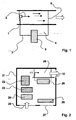
- the measuring instrument according to the invention for air-technical measured variables has a basic structure, as shown in FIG. 2; it consists of the components housing 21, VOC (air quality) sensor 22, humidity sensor 23, temperature sensor 24, air inlet 25, high voltage source 26, cable connection / 2nd air inlet 27, ion blower 28, air outlet 29th
- the high voltage generation by means of a piezoelectric component, similar to DE 101 290 41 , generated.
- the piezoelectric component is excited to oscillate by an electric frequency generator.
- a high AC voltage is tapped, rectified and fed to the ion blower.
- forced ventilated sensors - in particular temperature sensors - are used by fans. Due to the constant noise development, the sensors are installed behind the dashboard. In this respect, the temperature is measured approximately at the height of the legs of the passengers. It would be more useful, however, to measure the air temperature at about head height.
- the invention it is proposed to use artificially ventilated sensors with ion fans in the headrests or in the roof spars.
- the sensors Via data bus systems, the sensors can deliver their data to the central climate computer.
- Advantageous are the data freed from local influences, the increased response speed of the sensors and the absolute freedom from noise.
Landscapes
- Engineering & Computer Science (AREA)
- Chemical & Material Sciences (AREA)
- Physics & Mathematics (AREA)
- Mechanical Engineering (AREA)
- Combustion & Propulsion (AREA)
- General Engineering & Computer Science (AREA)
- Health & Medical Sciences (AREA)
- Signal Processing (AREA)
- Mathematical Physics (AREA)
- Thermal Sciences (AREA)
- Fuzzy Systems (AREA)
- Life Sciences & Earth Sciences (AREA)
- Biochemistry (AREA)
- Medicinal Chemistry (AREA)
- Analytical Chemistry (AREA)
- Food Science & Technology (AREA)
- General Health & Medical Sciences (AREA)
- General Physics & Mathematics (AREA)
- Immunology (AREA)
- Pathology (AREA)
- Air-Conditioning For Vehicles (AREA)
- Investigating Or Analyzing Materials By The Use Of Electric Means (AREA)
- Air Conditioning Control Device (AREA)
Description
- Die Erfindung betrifft einen Apparat zur elektronischen Messung lufttechnischer Größen wie Lufttemperatur, Luftfeuchte und Luftqualität oder Gaskonzentration.
- Die lufttechnischen Parameter wie Luftfeuchte, Lufttemperatur, Luftqualität oder Gaskonzentrationen sind Größen, welche für die Regelung / Steuerung raumlufttechnischer Anlagen (RTA) benötigt werden und aus diesem Grunde technisch erfasst bzw. gemessen werden müssen.
- Luftfeuchte wird zumeist als relative Feuchte, % r.F., angegeben und beschreibt den Sättigungsgrad der Luft mit Wasser bei gegebener Temperatur.
- Ein geeignetes kostengünstiges Messprinzip sind zum Beispiel beidseitig metallbedampfte Polymere, welche einen elektrischen Kondensator bilden. Die elektrisch zu messende Kapazität des Kondensators ist eine Funktion der Wasseraufnahme des Polymers, welche in einem Gleichgewichtszustand unter Einfluß der Luftfeuchte und der Umgebungstemperatur ist.
- Lufttemperatur wird in "Grad Celsius" angegeben, seltener in der physikalischen Notation "Grad Kelvin". Kostengünstige Messprinzipen nutzen den Einfluss der Temperatur auf elektrisch leitende Materialien, etwa auf einen Platinleiter. Es wird der Ohmsche Widerstand gemessen.
- Luftqualität wird durch den Anteil organischer Substanzen, nämlich VOC = volatile organic compounds, in der Luft angegeben und zwar in mg/m3. VOC sind zumeist auch geruchstragend und entstehen als Stoffwechselnebenprodukte bei Anwesenheit von Menschen und / oder als Ausdünstungen aus Kunststoffen, Materialien oder sonstigen chemischen Prozessen, wie Tabakrauch, Küchendämpfe, etc.
- Kostengünstige Messprinzipien nutzen breitbandig detektierende Metalloxid-Halbleifersensoren, welche alle oxidierbaren Luftbestandteile detektieren können. Eingebettet in komplexen Signalauswertungen sind kostengünstige, stabile und datentreue Messsensoren bekannt, etwa aus der
DE 195 43 296 5 oder derEP 96 118 420 - Detektoren zur Messung des von Menschen abgegebenen Kohlendioxid, CO2, sind ebenfalls bekannt; sie erfassen jedoch in nachteiliger Weise nicht die Anteile anderer organischer und gelegentlich toxischer Luftbestandteile, etwa Formaldehyd.
- Messgeräte zur Erfassung von einer oder mehrerer raumlufttechnischer Größen müssen sowohl in Räumen, Fahrzeugkabinen als auch in Luftkanälen installiert werden.
- Bekannt ist weiter, dass sogenannte Ortseinflüsse, zum Beispiel die Messung der Lufttemperatur und in besonderem Maße die der Luftfeuchte, erheblich verfälschen. Darunter sind solche Einflüsse zu verstehen, wie etwa Wärmestrahlung / Infrarot-Strahlung oder Wärme / Kältebrücken bei Montagebrücken bzw. zur Wand, auf der das Messgerät montiert ist.
- Bekannt ist von hochwertigen klimatechnischen Messgeräten, die Detektoren gegen Wärme- oder Kältebrücken thermisch sorgfältig zu isolieren und gegen thermische Strahlung abzuschirmen und die Detektoren künstlich mit Hilfe eines Ventilators zu belüften. Im Ergebnis werden damit Ortseinflüsse vermieden und die Präzision der Messung der tatsächlichen Luftparameter wird erhöht.
- Nachteilig ist hingegen, dass diese Messgeräte voluminös und sehr teuer sind und permanent das Geräusch des Ventilators zu hören ist. Für Anwendungen in Wohnraumumgebung oder in Automobilen sind diese Geräte daher nicht geeignet.
- Sensoren zur Erfassung der Konzentration von Gasen in Luft haben gelegentlich das Problem, dass das Gasgemisch nicht homogen ist und es zu lokalen Konzentrationsan- oder -abreicherungen kommen kann.
- Durch die
DE 100 21 067 A ist wenigstens ein elektromotorisch angetriebener Lüfter zum Belüften eines Sensors bekannt geworden, der beispielsweise Bestandteil einer geregelten Fahrzeugheizanlage ist, wobei der Lüfter ein Lüftergehäuse mit einem Einlass und einem Auslass aufweist. Innerhalb des Lüftergehäuses ist ein Lüfterrad antreibbar von einem bürstenlosen elektronisch kommutierten Elektromotor. Der Sensor, der beispielsweise ein Temperatursensor ist, ist beim oder im Einlass des Lüftergehäuses angeordnet, so dass bei angetriebenem Lüfterrad der Sensor mit der Luft belüftet wird, die sich das Lüftergebläse aus der Umgebung ansaugt. Das Belüften des Sensors in dieser Weise wird durchgeführt, damit ein Regler der Fahrzeugheizanlage schnell den zu ermittelnden Istwert angezeigt bekommt. Es wird hier vorgeschlagen, einen Induktionsmotor einzubauen, dessen antreibendes Drehfeld durch Fremdkommutierung erzwungen wird. Hierbei wird ausgenützt, dass unabhängig von der Stellung des jeweiligen Rotors des Induktionsmotors beim Einschalten ein konstruktiv bestimmbares Anlaufmoment zur Verfügung steht. - Aufgabenstellung der Erfindung ist es, ein Gerät zur Erfassung der Luftparameter mindestens einer der nachstehend genannten Größen zu erfassen, nämlich Luftfeuchte, in % rel. Feuchte, oder Lufttemperatur, in Grad Celsius, oder Luftqualität, in VOC-Anteil oder in CO2-Anteil, oder die Konzentration von Gasen in Luft.
- Die Lösung der Aufgabe besteht bei einem Apparat der eingangs genannten Gattung darin, dass ein oder mehrere Sensoren zur Erfassung einer oder mehrerer lufttechnischer Größen in einem einzigen Gehäuse untergebracht sind, wobei das Gehäuse zur Erzeugung einer Luftströmung durch einen Ventilator belüftet ist, welcher nach dem Prinzip eines geräuschlosen Ionengebläses arbeitet.
- Somit wird zur Erzeugung einer Luftströmung erfindungsgemäß vorgeschlagen, ein elektrostatisches Gebläse in Anlehnung an P 198 42 068 zu nutzen. Dazu wird Luft elektrisch etwa an Koronarspitzen ionisiert, wobei die gebildeten Ionen in einem elektrischen Feld auf eine Elektrode, Anode, zu beschleunigt werden und dabei Luftmoleküle aus der Umgebung mitreißen. Die Anode besteht aus einem Gitter oder aus gespannten Drähten, sodass zwar einige der Ionen aufgefangen werden, die beschleunigten Luftmoleküle jedoch über die Anode hinaus weiter in den Raum fliegen. Luftströmungen in der Größenordnung von 13m/sec lassen sich realisieren. Die Luftmenge, Volumen, bestimmt sich aus der Fläche der Anordnung. Ein elektrostatischer Lüfter erzeugt vorteilhaft absolut keine Geräusche.
- Kurzbeschreibung der Zeichnung, in der zeigen:
- Figur 1
- eine Erläuterung des Funktionsprinzips und
- Figur 2
- einen prinzipiellen Aufbau eines erfindungsgemäßes Messgerätes für lufttechnische Messgrößen.
- Gemäß der Figur 1 befindet sich in einem Luftkanal 1 auf einem Träger eine möglichst spitze Nadel 2 oder ein Bündel von elektrisch leitenden Spitzen, welche über eine elektrische Leitung 3 an den Minuspol einer hohen elektrischen Gleichspannung angeschlossen sind. Der Pluspol, also die Anode 6, wird aus einem Metallgitter oder aus einer Anordnung gespannter, dünner Drähte gebildet, welche über eine elektrische Leitung 4 an eine Hochspannungsquelle 5 angeschlossen ist. Um die Spitze der Nadel 2 bildet sich ein hohes elektrisches Feld, in welchem Luftmoleküle ionisiert werden. Die Ionen werden in dem Feld, welches sich zwischen der Nadel 2 und der Anode 6 bildet, beschleunigt und reißen dabei Luftmoleküle mit, was eine Luftströmung in Richtung Anode zur Folge hat. Währen die Ionen vom Anodengitter "eingefangen" werden, fliegen die beschleunigten Luftmoleküle aufgrund der innewohnenden kinetischen Energie weiter in den Raum hinaus. Der Wirkungsgrad kann durch eine oder mehrere Beschleunigungsgitter 7 verbessert werden.
- Ein lufttechnischer Sensor hat ein inneres Gehäusevolumen von beispielsweise 0,1 ltr. Wird ein Luftaustausch von ca. 5/min angestrebt, muss demnach ein Volumen von 0,51 ltr. / Minute gefördert werden.
- Ein elektrostatischer Lüfter mit einer Austrittsfläche von nur 5cm2 hat bei einer Austrittsgeschwindigkeit von 2m/sec ein Fördervolumen von 600cm3/min.
- Permanente Belüftung des Sensorgehäuses vermindert vorteilhaft den Einfluss von Ortseinflüssen, vor allem solche aus thermischer Strahlung oder durch Kälte oder Wärmebrücken.
- Das erfindungsgemäße Messgerät für lufttechnische Messgrößen hat einen prinzipiellen Aufbau, wie er in Figur 2 gezeigt ist; es besteht aus den Bauteilen Gehäuse 21, VOC (Luftgüte-) Sensor 22, Feuchtesensor 23, Temperatursensor 24, Lufteinlass 25, Hochspannungsquelle 26, Kabelanschluss / 2. Lufteinlass 27, Ionengebläse 28, Luftauslass 29.
- In einer Variante der Erfindung wird die Hochspannungserzeugung mit Hilfe eines piezoelektrischen Bauteils, ähnlich der
DE 101 290 41 , erzeugt. Dabei wird durch einen elektrischen Frequenzgenerator das piezoelektrische Bauteil zu Schwingungen angeregt. An anderer Stelle wird eine hohe Wechselspannung abgegriffen, gleichgerichtet und dem Ionengebläse zugeführt. - Speziell für die Erfassung klimatechnischer Größen in den Kabinen von Fahrzeugen aller Art, insbesondere von Automobilen, werden von Ventilatoren zwangsbelüftete Sensoren - insbesondere Temperatursensoren - eingesetzt. Aufgrund der permanenten Geräuschentwicklung werden die Sensoren hinter das Armaturenbrett eingebaut. Es wird insofern die Temperatur etwa in Höhe der Beine der Passagiere gemessen. Sinnvoller wäre es jedoch, die Lufttemperatur etwa in Kopfhöhe zu messen.
- Erfindungsgemäß wird vorgeschlagen, mit Ionengebläse künstlich belüftete Sensoren in die Kopfstützen oder in die Dachholme einzusetzen. Über Datenbussysteme können die Sensoren ihre Daten an den zentralen Klimacomputer liefern. Vorteilhaft sind die von Ortseinflüssen befreiten Daten, die erhöhte Ansprechgeschwindigkeit der Sensoren und die absolute Geräuschfreiheit.
- Gemeinsam ist allen erfindungsgemäßen Apparaten, dass sie folgende Merkmale haben, nämlich einen oder mehrere Sensoren zur Erfassung klimatechnischer Größen, wie etwa Luftqualität, Luftfeuchte oder Lufttemperatur sowie ein nach dem Prinzip der beschleunigten Luftionen arbeitendes Ionengebläse zum Austausch der Luft innerhalb des Gehäuses.
-
- Figur 1:
- 1
- Luftkanal
- 2
- Ionisationsspitze, nach dem Koronarprinzip arbeitend
- 3
- Elektrische Anschlussleitung für (-) -Pol, ca. 3000Volt Gleichspannung
- 4
- Elektrische Anschlussleitung für (+)-Pol, ca. 3000Volt Gleichspannung
- 5
- Hochspannungsquelle
- 6
- Gitterförmige Anode
- 7
- Beschleunigungsgitter
- Figur 2:
- 21
- Gehäuse
- 22
- VOC (Luftgüte-) Sensor
- 23, 24
- Feuchtesensor und Temperatur-Sensor
- 25
- Lufteinlass
- 26
- Hochspannungs-Quelle
- 27
- Kabelanschluss / 2. Lufteinlass
- 28
- Ionengebläse
- 29
- Luftauslass
Claims (8)
- Apparat zur elektronischen Messung lufttechnischer Größen wie Lufttemperatur, Luftfeuchte und Luftqualität oder Gaskonzentration,
dadurch gekennzeichnet,
dass ein oder mehrere Sensoren zur Erfassung einer oder mehrerer lufttechnischer Größen in einem einzigen Gehäuse untergebracht sind, wobei das Gehäuse durch einen Ventilator belüftet wird, welcher nach dem Prinzip eines geräuschlosen Ionengebläses arbeitet. - Apparat nach Anspruch 1, dadurch gekennzeichnet,
dass das Ionengebläse ein oder mehrere Beschleunigungsgitter aufweist. - Apparat nach Anspruch 1 oder 2, dadurch gekennzeichnet, dass sowohl das den oder die Sensoren tragende Gehäuse als auch das Ionengebläse miniaturisiert sind und zusammen eine kompakte, kleine Einheit bilden.
- Apparat nach einem der Ansprüche 1 bis 3, dadurch gekennzeichnet, dass die Hochspannungserzeugung mit Hilfe eines piezoelektrischen Wandlers erfolgt.
- Apparat nach mindestens einem der Ansprüche 1-4, dadurch gekennzeichnet, dass Sensoren des erfindungsgemäßen Prinzips in Automobilen eingesetzt sind.
- Apparat nach Anspruch 5, dadurch gekennzeichnet, dass Sensoren nach Anspruch 1-4 in Kopfstützen der Sitze von Automobilen eingebaut sind.
- Apparat nach Anspruch 5, dadurch gekennzeichnet, dass Sensoren nach Anspruch 1-4 in die Dachholme von Automobilen eingebaut sind.
- Apparat nach Anspruch 5, dadurch gekennzeichnet, dass Sensoren nach Anspruch 1-4 in den Dachhimmel von Automobilen eingebaut sind.
Applications Claiming Priority (3)
| Application Number | Priority Date | Filing Date | Title |
|---|---|---|---|
| DE10233755 | 2002-07-25 | ||
| DE10233755 | 2002-07-25 | ||
| PCT/DE2003/002473 WO2004017065A1 (de) | 2002-07-25 | 2003-07-23 | Zwangsbelüftete messeinrichtung zur erfassung lufttechnischer parameter |
Publications (2)
| Publication Number | Publication Date |
|---|---|
| EP1530717A1 EP1530717A1 (de) | 2005-05-18 |
| EP1530717B1 true EP1530717B1 (de) | 2007-11-28 |
Family
ID=30128353
Family Applications (1)
| Application Number | Title | Priority Date | Filing Date |
|---|---|---|---|
| EP03787720A Expired - Lifetime EP1530717B1 (de) | 2002-07-25 | 2003-07-23 | Zwangsbelüftete messeinrichtung zur erfassung lufttechnischer parameter |
Country Status (4)
| Country | Link |
|---|---|
| EP (1) | EP1530717B1 (de) |
| AU (1) | AU2003264235A1 (de) |
| DE (2) | DE10261921A1 (de) |
| WO (1) | WO2004017065A1 (de) |
Families Citing this family (5)
| Publication number | Priority date | Publication date | Assignee | Title |
|---|---|---|---|---|
| DE102005021708A1 (de) * | 2005-05-11 | 2006-11-16 | Hella Kgaa Hueck & Co. | Sensoranordnung zur Detektion der Beschlagsneigung |
| CN104816606B (zh) * | 2015-03-26 | 2016-08-31 | 盐城工学院 | 循环流通导流管式汽车乘员舱空气质量检测器 |
| DE102016200256A1 (de) | 2016-01-13 | 2017-07-13 | Robert Bosch Gmbh | Pumpvorrichtung und Partikeldetektor mit einer Pumpvorrichtung |
| DE202018100186U1 (de) | 2018-01-15 | 2018-01-26 | Sensirion Automotive Solutions Ag | Sensormodul zur Luftgütemessung |
| CN114061096A (zh) * | 2021-12-02 | 2022-02-18 | 浙江弩牌电器有限公司 | 空气调节组件及其使用方法 |
Family Cites Families (5)
| Publication number | Priority date | Publication date | Assignee | Title |
|---|---|---|---|---|
| US4606219A (en) * | 1983-07-05 | 1986-08-19 | Crucible S.A. | Gas detectors |
| JPS6020027A (ja) * | 1983-07-15 | 1985-02-01 | Mitsubishi Heavy Ind Ltd | 空気加熱・冷却装置 |
| DE19842068A1 (de) * | 1998-09-15 | 2000-03-16 | Brand Gerhart Rosemarie | Lufttechnische Anlage zum Transport von Luft in elektrostatischen Feldern |
| DE19900306A1 (de) * | 1999-01-07 | 2000-07-13 | Heinz Hoelter | Verfahren zum Betreiben eines Wärmetauschers für die energiesparende Wohnraumbelüftung mit integrierten Sprühelektroden |
| DE10021067A1 (de) * | 2000-04-28 | 2001-10-31 | Bosch Gmbh Robert | Elektromotorisch angetriebener Lüfter zum Belüften eines Sensors |
-
2002
- 2002-12-06 DE DE10261921A patent/DE10261921A1/de not_active Ceased
-
2003
- 2003-07-23 EP EP03787720A patent/EP1530717B1/de not_active Expired - Lifetime
- 2003-07-23 WO PCT/DE2003/002473 patent/WO2004017065A1/de not_active Ceased
- 2003-07-23 AU AU2003264235A patent/AU2003264235A1/en not_active Abandoned
- 2003-07-23 DE DE50308701T patent/DE50308701D1/de not_active Expired - Fee Related
Also Published As
| Publication number | Publication date |
|---|---|
| EP1530717A1 (de) | 2005-05-18 |
| DE50308701D1 (de) | 2008-01-10 |
| DE10261921A1 (de) | 2004-02-12 |
| WO2004017065A1 (de) | 2004-02-26 |
| AU2003264235A1 (en) | 2004-03-03 |
Similar Documents
| Publication | Publication Date | Title |
|---|---|---|
| EP1924836B1 (de) | Sensor für ultrafeine teilchen | |
| JP7574520B2 (ja) | 空調装置の汚染を測定するためのシステム | |
| EP2399124A1 (de) | Messgerät und verfahren zum erfassen des kohlenwasserstoffanteils in gasen | |
| EP1440695A1 (de) | Verfahren zur Aktivierung von Luftsauerstoff zum Abbau von VOC-Lasten und Keimen in geschlossenen Räumen sowie zur Aufrechterhaltung einer naturadäquaten Sauerstoffionen-und Ozonkonzentration | |
| EP1530717B1 (de) | Zwangsbelüftete messeinrichtung zur erfassung lufttechnischer parameter | |
| DE19842895C2 (de) | Anordnung zum Regeln der Innenraumtemperatur im Fahrgastraum eines Kraftfahrzeuges | |
| WO2021043963A1 (de) | Einrichtung zur luftbehandlung mit ionisationsmodul | |
| EP1483124B1 (de) | Klimagebläse | |
| DE102010003966B3 (de) | Sensoranordnung | |
| DE102016000666B4 (de) | Ionisationsvorrichtung und korrespondierende Belüftungsanordnung | |
| US7729101B2 (en) | Method and apparatus for monitoring and controlling ionizing blowers | |
| WO2018192711A1 (de) | Kompaktes messgerät und verfahren zum erfassen von kohlenwasserstoffen | |
| DE10013841A1 (de) | Vorrichtung zur automatischen Steuerung von Anlagen zur Luftionisation und Luftaufbereitung | |
| CN113945404B (zh) | 一种离子发生器浓度检测方法 | |
| DE10350591A1 (de) | Raumbediengerät mit integrierten Messvorrichtungen | |
| CN113945403B (zh) | 一种离子发生器浓度检测装置 | |
| DE102017210123A1 (de) | Luftleitsystem sowie Messsystem und Verfahren zum Ermitteln von wenigstens einem Parameter eines aus einem Luftausströmer austretenden Luftstroms | |
| EP0774742B1 (de) | Branddetektor | |
| DE29717626U1 (de) | Vorrichtung zum Messen von Luftparametern für ein Kraftfahrzeug | |
| DE4105598A1 (de) | Messeinrichtung zur erfassung von gasen mit einem sensor und einem gasfilter | |
| EP1257888B1 (de) | Verfahren und vorrichtung zur regelung der kapazität zwischen zwei elektroden in einem gas | |
| EP0785493A1 (de) | Verfahren zur Erzielung einer Behaglichkeitstemperatur in einem Raum und Anordnung zur Durchführung des Verfahrens | |
| WO2000016018A1 (de) | Verfahren und vorrichtung zum transport von gasen, insbesondere von luft | |
| Bitter et al. | Odour emissions from an HVAC-system | |
| DE102017210124A1 (de) | Luftleitsystem und Messsystem zum Messen von wenigstens einem Parameter eines aus einem Luftausströmer austretenden Luftstroms |
Legal Events
| Date | Code | Title | Description |
|---|---|---|---|
| PUAI | Public reference made under article 153(3) epc to a published international application that has entered the european phase |
Free format text: ORIGINAL CODE: 0009012 |
|
| 17P | Request for examination filed |
Effective date: 20050223 |
|
| AK | Designated contracting states |
Kind code of ref document: A1 Designated state(s): AT BE BG CH CY CZ DE DK EE ES FI FR GB GR HU IE IT LI LU MC NL PT RO SE SI SK TR |
|
| AX | Request for extension of the european patent |
Extension state: AL LT LV MK |
|
| DAX | Request for extension of the european patent (deleted) | ||
| GRAP | Despatch of communication of intention to grant a patent |
Free format text: ORIGINAL CODE: EPIDOSNIGR1 |
|
| GRAS | Grant fee paid |
Free format text: ORIGINAL CODE: EPIDOSNIGR3 |
|
| GRAA | (expected) grant |
Free format text: ORIGINAL CODE: 0009210 |
|
| AK | Designated contracting states |
Kind code of ref document: B1 Designated state(s): AT BE BG CH CY CZ DE DK EE ES FI FR GB GR HU IE IT LI LU MC NL PT RO SE SI SK TR |
|
| REG | Reference to a national code |
Ref country code: GB Ref legal event code: FG4D Free format text: NOT ENGLISH |
|
| REG | Reference to a national code |
Ref country code: IE Ref legal event code: FG4D Free format text: LANGUAGE OF EP DOCUMENT: GERMAN |
|
| REG | Reference to a national code |
Ref country code: CH Ref legal event code: EP |
|
| REF | Corresponds to: |
Ref document number: 50308701 Country of ref document: DE Date of ref document: 20080110 Kind code of ref document: P |
|
| PG25 | Lapsed in a contracting state [announced via postgrant information from national office to epo] |
Ref country code: NL Free format text: LAPSE BECAUSE OF FAILURE TO SUBMIT A TRANSLATION OF THE DESCRIPTION OR TO PAY THE FEE WITHIN THE PRESCRIBED TIME-LIMIT Effective date: 20071128 Ref country code: ES Free format text: LAPSE BECAUSE OF FAILURE TO SUBMIT A TRANSLATION OF THE DESCRIPTION OR TO PAY THE FEE WITHIN THE PRESCRIBED TIME-LIMIT Effective date: 20080311 Ref country code: SE Free format text: LAPSE BECAUSE OF FAILURE TO SUBMIT A TRANSLATION OF THE DESCRIPTION OR TO PAY THE FEE WITHIN THE PRESCRIBED TIME-LIMIT Effective date: 20080228 |
|
| NLV1 | Nl: lapsed or annulled due to failure to fulfill the requirements of art. 29p and 29m of the patents act | ||
| PG25 | Lapsed in a contracting state [announced via postgrant information from national office to epo] |
Ref country code: SI Free format text: LAPSE BECAUSE OF FAILURE TO SUBMIT A TRANSLATION OF THE DESCRIPTION OR TO PAY THE FEE WITHIN THE PRESCRIBED TIME-LIMIT Effective date: 20071128 Ref country code: BG Free format text: LAPSE BECAUSE OF FAILURE TO SUBMIT A TRANSLATION OF THE DESCRIPTION OR TO PAY THE FEE WITHIN THE PRESCRIBED TIME-LIMIT Effective date: 20080228 Ref country code: FI Free format text: LAPSE BECAUSE OF FAILURE TO SUBMIT A TRANSLATION OF THE DESCRIPTION OR TO PAY THE FEE WITHIN THE PRESCRIBED TIME-LIMIT Effective date: 20071128 |
|
| GBV | Gb: ep patent (uk) treated as always having been void in accordance with gb section 77(7)/1977 [no translation filed] | ||
| PG25 | Lapsed in a contracting state [announced via postgrant information from national office to epo] |
Ref country code: CZ Free format text: LAPSE BECAUSE OF FAILURE TO SUBMIT A TRANSLATION OF THE DESCRIPTION OR TO PAY THE FEE WITHIN THE PRESCRIBED TIME-LIMIT Effective date: 20071128 Ref country code: DK Free format text: LAPSE BECAUSE OF FAILURE TO SUBMIT A TRANSLATION OF THE DESCRIPTION OR TO PAY THE FEE WITHIN THE PRESCRIBED TIME-LIMIT Effective date: 20071128 |
|
| PG25 | Lapsed in a contracting state [announced via postgrant information from national office to epo] |
Ref country code: RO Free format text: LAPSE BECAUSE OF FAILURE TO SUBMIT A TRANSLATION OF THE DESCRIPTION OR TO PAY THE FEE WITHIN THE PRESCRIBED TIME-LIMIT Effective date: 20071128 Ref country code: SK Free format text: LAPSE BECAUSE OF FAILURE TO SUBMIT A TRANSLATION OF THE DESCRIPTION OR TO PAY THE FEE WITHIN THE PRESCRIBED TIME-LIMIT Effective date: 20071128 |
|
| EN | Fr: translation not filed | ||
| PG25 | Lapsed in a contracting state [announced via postgrant information from national office to epo] |
Ref country code: PT Free format text: LAPSE BECAUSE OF FAILURE TO SUBMIT A TRANSLATION OF THE DESCRIPTION OR TO PAY THE FEE WITHIN THE PRESCRIBED TIME-LIMIT Effective date: 20080428 |
|
| REG | Reference to a national code |
Ref country code: IE Ref legal event code: FD4D |
|
| PLBE | No opposition filed within time limit |
Free format text: ORIGINAL CODE: 0009261 |
|
| STAA | Information on the status of an ep patent application or granted ep patent |
Free format text: STATUS: NO OPPOSITION FILED WITHIN TIME LIMIT |
|
| PG25 | Lapsed in a contracting state [announced via postgrant information from national office to epo] |
Ref country code: IE Free format text: LAPSE BECAUSE OF FAILURE TO SUBMIT A TRANSLATION OF THE DESCRIPTION OR TO PAY THE FEE WITHIN THE PRESCRIBED TIME-LIMIT Effective date: 20071128 Ref country code: FR Free format text: LAPSE BECAUSE OF FAILURE TO SUBMIT A TRANSLATION OF THE DESCRIPTION OR TO PAY THE FEE WITHIN THE PRESCRIBED TIME-LIMIT Effective date: 20080912 |
|
| 26N | No opposition filed |
Effective date: 20080829 |
|
| PG25 | Lapsed in a contracting state [announced via postgrant information from national office to epo] |
Ref country code: GB Free format text: LAPSE BECAUSE OF FAILURE TO SUBMIT A TRANSLATION OF THE DESCRIPTION OR TO PAY THE FEE WITHIN THE PRESCRIBED TIME-LIMIT Effective date: 20071128 |
|
| PG25 | Lapsed in a contracting state [announced via postgrant information from national office to epo] |
Ref country code: GR Free format text: LAPSE BECAUSE OF FAILURE TO SUBMIT A TRANSLATION OF THE DESCRIPTION OR TO PAY THE FEE WITHIN THE PRESCRIBED TIME-LIMIT Effective date: 20080229 |
|
| REG | Reference to a national code |
Ref country code: CH Ref legal event code: PL |
|
| PG25 | Lapsed in a contracting state [announced via postgrant information from national office to epo] |
Ref country code: MC Free format text: LAPSE BECAUSE OF NON-PAYMENT OF DUE FEES Effective date: 20080731 |
|
| PG25 | Lapsed in a contracting state [announced via postgrant information from national office to epo] |
Ref country code: EE Free format text: LAPSE BECAUSE OF FAILURE TO SUBMIT A TRANSLATION OF THE DESCRIPTION OR TO PAY THE FEE WITHIN THE PRESCRIBED TIME-LIMIT Effective date: 20071128 |
|
| PG25 | Lapsed in a contracting state [announced via postgrant information from national office to epo] |
Ref country code: LI Free format text: LAPSE BECAUSE OF NON-PAYMENT OF DUE FEES Effective date: 20080731 Ref country code: CH Free format text: LAPSE BECAUSE OF NON-PAYMENT OF DUE FEES Effective date: 20080731 |
|
| PG25 | Lapsed in a contracting state [announced via postgrant information from national office to epo] |
Ref country code: CY Free format text: LAPSE BECAUSE OF FAILURE TO SUBMIT A TRANSLATION OF THE DESCRIPTION OR TO PAY THE FEE WITHIN THE PRESCRIBED TIME-LIMIT Effective date: 20071128 |
|
| PG25 | Lapsed in a contracting state [announced via postgrant information from national office to epo] |
Ref country code: AT Free format text: LAPSE BECAUSE OF NON-PAYMENT OF DUE FEES Effective date: 20080723 |
|
| PGFP | Annual fee paid to national office [announced via postgrant information from national office to epo] |
Ref country code: DE Payment date: 20090720 Year of fee payment: 7 |
|
| PG25 | Lapsed in a contracting state [announced via postgrant information from national office to epo] |
Ref country code: HU Free format text: LAPSE BECAUSE OF FAILURE TO SUBMIT A TRANSLATION OF THE DESCRIPTION OR TO PAY THE FEE WITHIN THE PRESCRIBED TIME-LIMIT Effective date: 20080529 Ref country code: LU Free format text: LAPSE BECAUSE OF NON-PAYMENT OF DUE FEES Effective date: 20080723 Ref country code: BE Free format text: LAPSE BECAUSE OF NON-PAYMENT OF DUE FEES Effective date: 20080731 |
|
| PG25 | Lapsed in a contracting state [announced via postgrant information from national office to epo] |
Ref country code: TR Free format text: LAPSE BECAUSE OF FAILURE TO SUBMIT A TRANSLATION OF THE DESCRIPTION OR TO PAY THE FEE WITHIN THE PRESCRIBED TIME-LIMIT Effective date: 20071128 |
|
| PG25 | Lapsed in a contracting state [announced via postgrant information from national office to epo] |
Ref country code: IT Free format text: LAPSE BECAUSE OF NON-PAYMENT OF DUE FEES Effective date: 20080731 |
|
| PG25 | Lapsed in a contracting state [announced via postgrant information from national office to epo] |
Ref country code: DE Free format text: LAPSE BECAUSE OF NON-PAYMENT OF DUE FEES Effective date: 20110201 |
|
| REG | Reference to a national code |
Ref country code: DE Ref legal event code: R119 Ref document number: 50308701 Country of ref document: DE Effective date: 20110201 |