EP1530345B1 - Verschiebbares Mobilkommunikationsendgerät - Google Patents
Verschiebbares Mobilkommunikationsendgerät Download PDFInfo
- Publication number
- EP1530345B1 EP1530345B1 EP04025590A EP04025590A EP1530345B1 EP 1530345 B1 EP1530345 B1 EP 1530345B1 EP 04025590 A EP04025590 A EP 04025590A EP 04025590 A EP04025590 A EP 04025590A EP 1530345 B1 EP1530345 B1 EP 1530345B1
- Authority
- EP
- European Patent Office
- Prior art keywords
- housing
- sliding
- guide
- slider
- mobile communication
- Prior art date
- Legal status (The legal status is an assumption and is not a legal conclusion. Google has not performed a legal analysis and makes no representation as to the accuracy of the status listed.)
- Expired - Lifetime
Links
Images


Classifications
-
- H—ELECTRICITY
- H04—ELECTRIC COMMUNICATION TECHNIQUE
- H04M—TELEPHONIC COMMUNICATION
- H04M1/00—Substation equipment, e.g. for use by subscribers
- H04M1/02—Constructional features of telephone sets
- H04M1/0202—Portable telephone sets, e.g. cordless phones, mobile phones or bar type handsets
- H04M1/0206—Portable telephones comprising a plurality of mechanically joined movable body parts, e.g. hinged housings
- H04M1/0208—Portable telephones comprising a plurality of mechanically joined movable body parts, e.g. hinged housings characterized by the relative motions of the body parts
- H04M1/0214—Foldable telephones, i.e. with body parts pivoting to an open position around an axis parallel to the plane they define in closed position
-
- H—ELECTRICITY
- H04—ELECTRIC COMMUNICATION TECHNIQUE
- H04M—TELEPHONIC COMMUNICATION
- H04M1/00—Substation equipment, e.g. for use by subscribers
- H04M1/02—Constructional features of telephone sets
- H04M1/0202—Portable telephone sets, e.g. cordless phones, mobile phones or bar type handsets
- H04M1/0206—Portable telephones comprising a plurality of mechanically joined movable body parts, e.g. hinged housings
- H04M1/0208—Portable telephones comprising a plurality of mechanically joined movable body parts, e.g. hinged housings characterized by the relative motions of the body parts
- H04M1/0235—Slidable or telescopic telephones, i.e. with a relative translation movement of the body parts; Telephones using a combination of translation and other relative motions of the body parts
- H04M1/0237—Sliding mechanism with one degree of freedom
-
- H—ELECTRICITY
- H04—ELECTRIC COMMUNICATION TECHNIQUE
- H04M—TELEPHONIC COMMUNICATION
- H04M1/00—Substation equipment, e.g. for use by subscribers
- H04M1/02—Constructional features of telephone sets
- H04M1/0202—Portable telephone sets, e.g. cordless phones, mobile phones or bar type handsets
- H04M1/0206—Portable telephones comprising a plurality of mechanically joined movable body parts, e.g. hinged housings
- H04M1/0208—Portable telephones comprising a plurality of mechanically joined movable body parts, e.g. hinged housings characterized by the relative motions of the body parts
- H04M1/0225—Rotatable telephones, i.e. the body parts pivoting to an open position around an axis perpendicular to the plane they define in closed position
Definitions
- the present invention relates generally to a mobile communication terminal, and in particular, to a sliding-type or slidable mobile communication terminal with two or more housings configured so that the one housing is allowed to slide in a longitudinal direction of the other housing to open or close a keypad section on the first housing.
- a mobile telephone terminal is a portable mobile station that provides wireless communication services to its subscriber while wirelessly communicating with its base station. Rapid development in the field of information and telecommunication business has made it possible for mobile users to use a variety of functions and types of mobile phones available on the market. These mobile telephone terminals are generally classified into three or more types of terminals, such as, e.g., a bar-type terminal, a flip-type terminal with a flip cover, and a foldable terminal with a folder adapted to be open and closed about a main body at a given angle.
- the bar-type terminal is generally formed with a single body housing configured so that various data input/output means and a receiver and transmitter set are arranged on the housing, and a keypad assembly utilized as a data input/output means is fully exposed.
- a bar-type terminal is often apt to operate in error due to careless manipulation by its user, and its design requires a relatively long distance between the receiver set and the transmitter set which may lead to serious limitations in making the terminal smaller.
- the flip-type terminal generally consists of a main body, a flip member and a hinge module for coupling the main body and the flip member, in which the main body is provided with a data input/output means, that is, a keypad, and a receiver and transmitter set.
- a data input/output means that is, a keypad
- receiver and transmitter set This type of terminal can prevent any undesired operation error or malfunction since the flip member is adapted to fully cover the keypad when the flip member is closed, but the design of this type of terminal also requires a relatively long distance between the receiver set and the transmitter set, which results in serious limitations in making smaller terminal.
- the folder-type or foldable terminal generally consists of a main body, a folder and a hinge module for coupling the main body and the folder, so that rotation of the folder allows opening or closure of the folder with respect to the main body.
- the main body is provided with a data input/output means, that is, a keypad and a receiver set.
- a data input/output means that is, a keypad and a receiver set.
- the hinge module for rotatably coupling the flip member or the folder with the main body operates in such a manner that when the flip or folder of the mobile terminal is opened to rotate up to a specified threshold angle about the main body, a continuous acting force is generated by the hinge module and is applied in the direction of opening without application of additional external force by a user, while when the flip or folder of the mobile terminal is rotated during closing below a specified threshold angle about the main body, a continuous acting force is generated by the hinge module and is applied in the direction of closure without application of more force by the user.
- a sliding type of mobile terminal has recently been in wide use and consists of two housings in which one housing is slidably opened or closed with respect to the other housing.
- these sliding type mobile terminals have not yet been proposed with a variety of different designs in structure, and for this reason, its users may feel some inconvenience in that they have, to manually slide one housing with respect to the other housing to open or close it.
- EP 1501260 A which was published after the priority date of the present application, refers to a slide type portable terminal wherein the described slide type portable terminal includes a slide unit that can slide relative to a surface of the main unit to cause each of a plurality of key sections of a main unit to be covered and exposed. Furthermore, the terminal includes a slide driving mechanism for causing the slide unit to slide using restorative forces.
- the described slide mechanism includes coil springs guided by guide bars.
- the guide bars have both ends rotatably coupled to the main and slide units, respectively, such that the lengths of portions of the guide bars can change as the slide unit is moved.
- US 2003/119544 A1 refers to a communications device having a sliding key pad cover.
- a spring mechanism which comprises at least one guide rod, an end of each guide rod attached to the backside mechanics of the sliding keypad cover, each guide rod having a travel limit.
- a spring mechanism further includes a guide frame having at least one guide hole, the at least one guide hole for receiving at least one guide rod. Additionally, the spring mechanism comprises a spring positioned around the guide rod and between the at least one guide hole and the travel limit.
- the object of the present invention to provide a sliding type mobile communication terminal having a plurality of housings adapted to allow a user to control the opening and closure operation with more ease and convenience.
- a sliding type mobile communication terminal having a first housing and a second housing adapted to allow the first housing to be opened or closed using a sliding movement on the first housing in a longitudinal direction of the first housing.
- the terminal includes a spring module adapted for providing a sliding force, along the longitudinal direction of the first housing, in a first direction for allowing closure of the second housing within a predetermined range of distance, and for providing the sliding force in a second direction for allowing opening of the second housing beyond the predetermined range of distance, the spring module havng at least one link bar rotatably coupled at one end onto the first housing; at least one coil spring supported by one end of the link bar and coupled to enclose the link bar; and at least one slider slidably coupled with respect to the link bar so as to be acted upon by an elastic force from the coil spring, and also slidably coupled onto the second housing.
- a sliding type mobile communication terminal having a first housing and a second housing adapted to allow the first housing to be opened or closed by means of a sliding movement on the first housing in a longitudinal direction of the first housing.
- the terminal includes a spring module configured for providing a sliding force, along the longitudinal direction of the first housing, in a first direction for allowing closure of the second housing within a predetermined range of distance, and for providing the sliding force in a second direction for allowing opening of the second housing beyond the predetermined range of distance, the spring module having at least one link bar, one end of the link bar being rotatably coupled with one side of a front surface of the first housing, and the other end of the link bar being rotatably coupled with the second housing, so that the link bar is allowed to slide in a direction perpendicular to the direction of movement in the second housing; and at least one coil spring supported at one end by the second housing and at an opposite end by the other end of the link bar, for providing an elastic force in a direction in which
- a sliding type mobile communication terminal having a first housing and a second housing, the second housing adapted to allow the first housing to be opened or closed by means of a sliding movement on the first housing in a longitudinal direction of the first housing.
- the terminal includes a spring module having a sliding guide fixedly coupled to one side surface of the first housing, a slider fixedly coupled to one side surface of the second housing to allow a sliding movement on the sliding guide, at least one pair of one guide rods each fixed to one end of both sides of the slider, for slidably coupling with the sliding guide in the longitudinal direction, and an elastic means interposed between the sliding guide and the slider for providing an elastic force; and the elastic means configured to provide the sliding force, along the longitudinal direction of the first housing, in a first direction to allow closing of the first housing within a predetermined range of distance, and to provide the sliding force in a second direction to allow opening of the first housing beyond the predetermined range of distance.
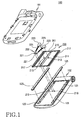
- the sliding type of mobile terminal 100 includes a first housing 101 and a second housing 102, the second housing being coupled with the first housing in a face to face relation with each other.
- the second housing 102 is provided with guide rails 125 and a spring module 200 for movably coupling the second housing 102 with the first housing in the longitudinal direction of the first housing 101.
- the first housing 101 is provided on its front surface with a keypad assembly 111 (shown in FIG. 8) and a transmitter 113 (shown in FIG. 8) with a microphone set.
- a sliding operation of the second housing 102 on the first housing 101 in its longitudinal direction allows a section with the keypad and transmitter to be open or closed.
- the second housing 102 is coupled with the first housing 101 in a sliding relation in its longitudinal direction, and is equipped with a receiver 117 (shown in FIG. 8) with a speaker, a display unit 115, and a multiplicity of function keys 119.
- the display unit is made from various display elements such as liquid crystal display (LCD), thin film transistor (TFT), etc.
- LCD liquid crystal display
- TFT thin film transistor
- On the back side 121 of the second housing 102 are installed a pair of guide rails 125 for smooth sliding movement of the first housing.
- Guide rails 125 which may be formed of an extended H-beam with side recesses, is fixed to a linkage groove formed in the longitudinal direction on the back side of the second housing 102.
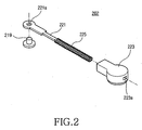
- the spring module 200 is coupled onto the first housing 101 so as to provide an elastic force for movement of the second housing 102 in either direction for opening or closing of the keypad and transmitter section on the mobile terminal.
- the spring module 200 is provided with a module housing 201 and a link assembly 202 equipped on the module housing 201, and the link assembly 202 is further provided with a link bar 221, sliders 223 and a coil spring 225.
- the module housing 201 is coupled to the front surface of the first housing 101 and is provided with a pair of first protrusions 213 on its inner surface 211, so that the sliders 223 are rotatably coupled about the first protrusions 213. Between the first protrusions 213 is an opening 215 extending in the longitudinal direction.
- the pair of first protrusions 213 are preferably arranged in the middle position of the opening 215 or in vicinity of the center position of the opening, symmetrical to the opening center.
- On the outer side of the module housing 201 is arranged a guide recess 217 corresponding to the guide rail 125. The longitudinal movement of the guide rail 125 within the guide recess 217 allows the second housing 102 to slide on the first housing 101 in its longitudinal direction.
- One end of the link bar 221 is rotatably coupled to the back side of the second housing 102 through the opening 215.
- a pair of second protrusions 219 may be arranged on the back side of the second housing 102, and a hole 221 a for rotatable coupling with the second protrusion 219 may be formed in one end of the link bar 221.
- the second protrusions 219 may be preferably arranged symmetrically with respect to each other, and project to the inside of the module housing 201 through the opening 215 thereof. As such, as the second housing 102 slidingly moves in the longitudinal direction of the first housing 101, the second protrusion 219 is allowed to move along the longitudinal direction of the opening 215.
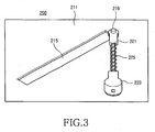
- the coil spring 225 encloses the link bar 221 and its both ends are supported by one of the link bar 221 and the slider 223. The coil spring 225 will provide an elastic force upon the slider 223 as the slider 223 becomes more distant from one end of the link bar 221.
- the coil spring 225 provides elasticity to the slider 223 as the slider 223 becomes more distant from one end of the link bar 221.
- the position of the slider 223 coupled onto the first protrusion 213 is kept fixed as in FIG. 3.
- the elasticity in the coil spring 225 acts in the direction that the second protrusions 219 are positioned on both ends of the opening 215.
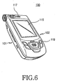
- FIG. 6 shows a perspective view of the sliding type mobile terminal 100 as shown in FIG. 1 in a fully closed position
- FIG. 7 shows a perspective view of the sliding type mobile terminal 100 with the second housing 102 partially opened to allow the keypad 111 and the transmitter 113 of the first housing 101 to be partially exposed.
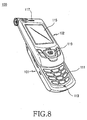
- FIG. 8 shows a perspective view of the sliding type mobile terminal 100 in the fully opened position.
- the second protrusions 219 are positioned in one end of the opening 215 in the module housing 201 by means of the elastic force by the coil spring 225, as shown in FIG. 3.
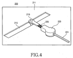
- the second protrusion 219 approaches the first protrusion 213 so that the elastic force accumulated in the coil spring 225 increases gradually, as shown in FIG. 4.
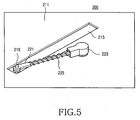
- the second protrusion 219 passes the closest position to the first protrusion 213, the second protrusion 219 becomes further spaced apart from the first protrusion 213 due to the elastic force accumulated in the coil spring 225 until it is positioned in the other end of the opening 215, as shown in FIG. 5.
- the second housing 102 allows the first housing 101 to fully open utilizing the elastic force of the coil spring 225.
- the user slides the second housing 102 onto the first housing 101.
- the user applies force to the second housing 102 to slide the second housing only to the point where the second protrusion 219 passes the closest position to the first protrusion 213, the second housing 102 will then move itself to the position where the first housing 101 is fully closed, by means of the elastic force of the coil spring 225.
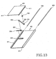
- sliding type mobile communication terminal 900 includes a first housing 901 and a second housing 902, the second housing 902 having a sitting groove 921 having a given depth on its back side and being coupled to face the first housing 901.
- a spring module 300 for movably coupling the second housing 902 in the longitudinal direction of the first housing 901 is provided.
- the spring module 300 provides an elastic force to allow the second housing 902 to be closed within a specified range of distance along the longitudinal direction of the first housing 901 and also provides an elastic force to allow the second housing 902 to be opened beyond the specified range of distance along the longitudinal direction of the first housing 901.
- the spring module 300 includes a first sliding base 301, a second sliding base 302, a link bar 303 and a coil spring 339.
- the first sliding base 301 is preferably in the form of a plate coupled to a front surface of the first housing 901 and is provided along both side edges with guide ribs 313, each extending in the longitudinal direction of the first housing 901.
- On a front surface of the first sliding base 301 is disposed a rotating hole 311 to which the link bar 303 is coupled.
- the first sliding base 301 may be configured in the structure incorporated into the first housing 901, in which case the guide rib 313 would project by a given height on the front surface of the first housing 901.
- the second sliding base 302 is preferably in the form of a plate coupled to a back surface of the Second housing 902 and is configured to face the first sliding base 301. Both side ends of the second sliding base 302 form edges facing each other, and are respectively provided with a guide groove 321 to match the guide rib 313.
- the guide groove 321 extends in the longitudinal direction of the first housing 901 for slideable engagement with the guide rib 313.
- the second sliding base 302 is slidably coupled with the first sliding base 301, thereby facing each other.
- the second sliding base 302 is provided with a sliding groove 322 extending in a direction perpendicular to the guide groove 321.
- the sliding groove 322 may be formed to pass through the front and back sides of the second sliding base 302 or in the form of recess having a given depth.
- the second sliding base 302 may be formed in the structure incorporated into the back side of the second housing 902.
- the elastic force in the coil spring 339 acts upon the second sliding base 302 through the link bar 303 to slide the second housing 902 in the longitudinal direction of the first housing 901. That is to say, the second sliding base 302 moves in the longitudinal direction on the first sliding base 301 with help of the elastic force in the coil spring 339.
- One end of the link bar 303 is rotatably coupled to the rotating hole 311 in the first sliding base 301, and its other end is rotatably and slidably coupled to the sliding groove 322 in the second sliding base 302.
- a rotating pin 335 is provided in one end 331 of the link bar 303.
- the rotating pin 335 may be incorporated into the end of the link bar 303 for rotatably coupling with respect to the rotating hole 311.
- a slider 337 is provided in the other end 333 of the link bar 303.
- the slider 337 is configured to slidably move within the sliding groove 322, so that its one end can be rotatably coupled with the other end 333 of the link bar 303.
- the slider 337 can be constructed in cylindrical form, so that the slider 337 could rotate in itself inside the sliding groove 322.
- the slider 337 may be incorporated into the other end 333 of the link bar 303.
- the coil spring 339 is equipped within the sliding groove 322, one end of which coil spring is supported by one end of the sliding groove 322 and other end of which coil spring is supported by the slider 337, so that the slider 337 moves in the direction approaching one side edge of the second sliding base 302 within the sliding groove 322, thereby providing the elastic force. That is to say, the other end 333 of the link bar 303 is subject to the elastic force for movement in the direction approaching one end of the first sliding base 301.
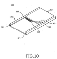
- FIG. 10 illustrates the spring module 300 in the case in which the second housing 902 and the first housing 901 are closed.
- the second sliding base 302 is positioned underneath the first sliding base 301.
- the elasticity accumulated in the coil spring 339 is at a minimum and the other end 333 of the link bar 303 is placed in the furthest position with respect to the edge of the second sliding base 302.
- the second sliding base 302 moves along the direction indicated by arrow 1 and the other end 333 of the link bar 303 moves along the direction indicated by arrow 2, so that it moves closer to the edge the second sliding base 302 to thereby accumulate the elasticity into the coil spring 339.
- the elastic force accumulated in the coil spring 339 when the sliding groove 322 is straight in line with the link bar 303, is the maximum level.
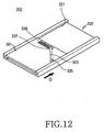
- FIG. 12 shows the second housing 902 fully moved upwardly with respect to the first housing 901.
- the spring module 300 provides the elastic force in a direction in which the second housing 902 either closes or opens with respect to the first housing 901. If the user allows the second housing 902 to move beyond the position where the link bar 303 is placed in line with the sliding groove 322, then the second housing 902 is allowed to move due to the elastic force in the spring module 300.
- the spring module 400 of the sliding type mobile terminal according to a third embodiment of the present invention includes a first sliding base 401, a second sliding base 402, a link bar 303 and a coil spring 339.
- the first sliding base 401 is in the form of a plate having in each side end a first guide groove 411 extending in the longitudinal direction.
- the second sliding base 402 is coupled with the first sliding base 401 in face-to-face relation, and second guide grooves 421 are arranged in its inner sides to face the first guide grooves 411.
- first and second guide grooves 411 and 421, and guide rails 409 are described in the form of a rod with annular profile, but it will be apparent that they may be configured in any type of polygonal shape.
- the first sliding base 301 is configured to slide in the longitudinal direction of the second sliding base 302.
- coupling components such as the link bar 303 or the rotating pin 335 interposed between the first and second sliding bases 301 and 302.
- the first sliding base 401 may be coupled in a facing relation with the second sliding base 402, so that after determining the position of the link bar 303 or the rotating pin 335 the first sliding base 401 is arranged at a position corresponding to the determined position, the guide rails 409 may be inserted. Therefore, it will be understood that the spring module 400 according to this embodiment of the present invention utilizes the guide rails 409 for easy assembly.
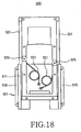
- Spring module 500 includes a sliding guide 501, a slider 502 and a pair of torsion springs 503.
- the sliding guide 501 is configured in the form of a plate with guide ribs 511 arranged in its sides and is provided, on its both side ends, with a coupling rib 519 for coupling with the first housing of the terminal.
- Each guide rib 511 is arranged adjacent to each coupling rib 519, extending in the longitudinal direction in a face-to-face relation to each other.
- a guide recess 513 is respectively formed in the inner side of each guide rib 511, extending in the longitudinal direction, for supporting the both side ends of the slider 502.
- the sliding guide 501 is fixed onto a front surface of the first housing of the sliding type mobile terminal.
- a guide rod 521 extending in the longitudinal direction, so that the slider 502 is supported by the guide recess 513 and allowed to move slidingly on the sliding guide 501 in the lengthwise direction.
- the guide rod 521 may be detachably secured to the slider 502 or incorporated into the slider 502.
- the guide rod 521 is detachably fixed to the slider 502, and support ribs 527 are formed in each end of both sides of the slider 502, respectively, extending along the side of the slider.
- the guide rods 521 preferably have a round form of cross section, and the guide recess 513 is formed accommodate the shape of the guide rods 521, so that a gap or play between the sliding guide 501 and the slider 502 can be reduced and the slider 502 carries out a sliding operation in a smooth manner.
- the cross section of the guide rod 521 may be of any polygon.
- the torsion spring 503 includes a coil section 531 for generating an elastic force, and a pair of free ends 533 extending from the coil section 531.
- the sliding guide 501 and the slider 502 are respectively provided with fixing holes 515 and 525 for coupling the free ends 533 of the torsion springs 503.
- the torsion spring 503 is then interposed between the sliding guide 501 and the slider 502.
- a pair of torsion springs 503 is shown by way of example in this particular embodiment, it would be appreciated by those skilled in the art that one or more torsion springs 503 may be used as an alternative embodiment.
- the slider 502 is located at one end of the sliding guide 501 by means of the elastic force from the torsion spring 503, in the assembled state of the spring module 500, as initially shown in FIGs. 15 and 17.
- the free ends 533 of the torsion spring 503 come close to each other to accumulate the elasticforce.
- the free ends 533 approach each other in the closest position to render the elasticity stored in the torsion spring 503 at the maximum.
- the maximum position of the elastic force stored in the torsion spring 503 depends upon positions of the fixing holes 515 and 525 to which the free ends 533 are fixed.
- FIG. 6 illustrates the mobile terminal 100 with its first housing 101 fully closed with respect to the second housing 102, wherein the slider 502 is adapted to underlie the sliding guide 501.
- the elastic force stored in the torsion spring 503 gradually increases.
- the elastic force by the torsion spring 503 effects opening of the first housing 101 by the second housing 102 while passing the nearest approaching position of the free ends 533.
- the second housing 102 is allowed to move further upwardly toward the upper end of the first housing 101, as shown in FIG. 8, even when the user ceases applying force to the second housing 102.
- the closing operations in the first housing 101 are to be carried out in the reverse sequence to the opening operations.
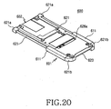
- the spring module 600 of the sliding type mobile terminal includes a sliding guide 601, a slider 602 and torsion springs 603.
- Each side end of the sliding guide 601 is provided with a guide rib 611, respectively.
- These two guide ribs 611 are positioned to face each other on both side ends of the sliding guide 601, extending in its longitudinal direction along the side end.
- the inner side of the respective guide ribs 611 is respectively provided with a guide recess 611a extending in the longitudinal direction, for supporting both side ends of the slider 601, and a guide hole 611 b is respectively formed into the guide rib 611, in the lengthwise direction.
- the sliding guide 601 is installed in the front side of the mobile terminal.
- Both side ends of the slider 602 each are slidably supported within the guide recesses 611 a of the sliding guide 601.
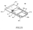
- the slider 602 is provided with an evasion hole 626a passing through the slider, an evasion recess 626b ⁇ FIG. 21) extending from the evasion hole to one end thereof, and a pair of guide rods 621 equipped in the both side ends, in its lengthwise direction, along the guide ribs 611, respectively.
- These guide rods are respectively fixed to the slider 602 and inserted into the guide holes 611b in the guide ribs 611.
- the slider 602 is supported by the guide recesses 611a and guide holes 611b of the sliding guide 601 to allow sliding movement in its longitudinal direction.
- the slider 602 is provided with support ribs 621a and 621b for coupling of the guide rods 621.
- These support ribs 621 and 621b consist of a pair of first support ribs 621a each extending in the side direction from one edge of the slider 602 and a pair of second ribs 621b formed on a fixing element 623 coupled with the other end of the slider 602.
- the fixing element 623 is configured so that it is coupled to the other end of the slider 602 by means of screws, and that the second support ribs 621a respectively extend in the side direction of the slider 602.
- the first and second support ribs are positioned to face each other in one side of the slider.
- the guide ribs 611 of the sliding guide 601 are positioned between the first and second support ribs 621a and 621b of the slider 602, the guide ribs 611 and the support ribs 621a and 621b also function as a stopper for limiting the moving range of the slider 602.
- the inner sides of the support ribs may be respectively provided with any suitable buffering material for reducing noises or impacts to be possibly created upon collision between the guide ribs 611 and the support ribs 621a and 621b.
- coupling of the guide rods 621 with the slider 602 may be configured in the same manner as the preceding embodiment, such as by pressing pins.
- the slider 602 is attached to the backside of the second housing of the sliding-type mobile terminal to face the sliding guide 601.
- a flexible printed circuit board 609 drawn out from the second housing extends through evasion hole 626a and evasion recess 626b to the first housing.
- the evasion hole 626a and the evasion recess 626b have enough width and depth to protect the flexible printed circuit board 609 from interfering with other components, fully taking into account the width and depth of the flexible printed circuit board 609 itself.
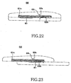
- the torsion spring 603 is provided with a coil section 631 and a pair of free ends 633 each extending from the coil section 631, the coil section 631 providing elastic force.
- the sliding guide 601 and the slider 602 are respectively provided with fixing holes 615 and 625 for coupling the free ends 633 of the torsion springs 603. When the free ends 633 are respectively coupled to the fixing holes 615 and 625 of the sliding guide 601 and the slider 602, the torsion springs 603 are then interposed between the sliding guide 601 and the slider 602.
- torsion springs 603 Although only one pair of the torsion springs 603 was shown by way of example in this particular embodiment, it would be appreciated by those skilled in the art that one or more pair of torsion springs may be used as an alternative embodiment of the invention. Further, although in this specific embodiment the torsion spring 603 is used to form an elastic means between the sliding guide 601 and the slider 602, it would be also appreciated by those skilled in the art that other elastic means may be configured with those links and coil springs as disclosed with reference to the preceding embodiments, for implementation of the same purpose and effects of the invention.
- the sliding-type mobile terminal having the spring modules according to the present invention would be considerably convenient to its user, because it enables a semi-automatic operation so that once the user forces the second housing to move upwardly or downwardly only by a predetermined short distance, then the first housing is smoothly opened or closed with the aid of the elastic force from the elastic means.
- the sliding-type mobile terminal uses coil springs and a slider on the link bar, as a means for sliding the second housing, so that the sliding open/close operations of the second housing can be carried out in a semi-automatic manner for the user's convenience.
- guide rails or guide rods are used for coupling a pair of sliding bases or a sliding guide and a slider in a slidable manner, thereby allowing reduction of the play gaps between the various mechanical parts of the mobile terminal, which results in more stable operation of the sliding open/close operations of the second housing.
- Such reduction in the play gaps between those mechanical parts and more stable sliding operation may be implemented more effectively using a round cross-section of guide rods.
Landscapes
- Engineering & Computer Science (AREA)
- Signal Processing (AREA)
- Telephone Set Structure (AREA)
Claims (19)
- Schiebe-Mobilkommunikations-Endgerät, das ein erstes Gehäuse (101), ein zweites Gehäuse (102) und ein Federmodul (200) aufweist, wobei das erste Gehäuse durch eine Schiebebewegung in einer Längsrichtung in Bezug auf das zweite Gehäuse geöffnet oder geschlossen wird und das Federmodul umfasst:wenigstens einen Verbindungsstab (221), der drehbar an einem Ende des ersten Gehäuses angebracht ist;wenigstens eine Schraubenfeder (225), die an einem Ende des Verbindungsstabes gelagert ist und den Verbindungsstab umschließt;ein Schiebeteil (223), das in Bezug auf den Verbindungsstab verschiebbar angebracht ist, so dass eine elastische Kraft von der Schraubenfeder darauf wirkt, und das auch drehbar an einem Gehäuse (201) des Federmoduls angebracht ist; undein Paar erster Vorsprünge (213), die an einer vorderen Fläche des Federmodulgehäuses jeweils zur drehbaren Verbindung mit dem Schiebeelement angeordnet sind, und ein Paar zweite Vorsprünge (219), die so gestaltet sind, dass sie von der hinteren Fläche des zweiten Gehäuses zur drehbaren Verbindung mit einem Ende des Verbindungsstabes vorstehen,wobei das Federmodul so gestaltet ist, dass es eine Schiebekraft entlang einer Längsrichtung des ersten Gehäuses in einer ersten Richtung erzeugt, um Schließen des ersten Gehäuses in Bezug auf das zweite Gehäuse innerhalb eines vorgegebenen Bereiches einer Wegstrecke zu ermöglichen, und eine Schiebekraft in einer zweiten Richtung erzeugt, um Öffnen des ersten Gehäuses in Bezug auf das zweite Gehäuse über den vorgegebenen Bereich einer Wegstrecke hinaus zu ermöglichen, und wobei das Federmodulgehäuse an der vorderen Fläche des ersten Gehäuses angebracht ist und das Federmodulgehäuse mit dem Paar erster Vorsprünge versehen ist, die sich von einer Innenfläche desselben aus erstrecken, und wobei das Federmodulgehäuse eine Öffnung hat, die so gestaltet ist, dass sie sich in der Längsrichtung des ersten Gehäuses auf das Paar zweiter Vorsprünge ausgerichtet und zwischen dem Paar erste Vorsprünge erstreckt.
- Schiebe-Mobilkommunikations-Endgerät nach Anspruch 1, wobei der Verbindungsstab an dem Federmodulgehäuse angebracht ist, dessen eines Ende mit den zweiten Vorsprüngen durch die Öffnung hindurch verbunden ist.
- Schiebe-Mobilkommunikations-Endgerät nach Anspruch 1 oder 2, wobei sich die zweiten Vorsprünge gleitend entlang der Öffnung bewegen und wenn sie in der Mitte der Öffnung positioniert sind, die zweiten Vorsprünge am nächsten an den ersten Vorsprüngen liegen.
- Schiebe-Mobilkommunikations-Endgerät nach einem der Ansprüche 1 bis 3, das des Weiteren ein Paar Führungsschienen (125), die jeweils an einer Rückseite des zweiten Gehäuses angeordnet sind, und ein Paar Führungsnuten (217) umfasst, die jeweils in einer Seite des Federmodulgehäuses angeordnet sind, um die Führungsschienen aufzunehmen, wobei die Führungsnuten so eingerichtet sind, dass sie die Schiebebewegung in der Längsrichtung entlang der Führungsschienen ermöglichen.
- Schiebe-Mobilkommunikations-Endgerät nach einem der Ansprüche 1 bis 4, wobei die Verbindungsstäbe symmetrisch zueinander an der Fläche des Federmodulgehäuses angeordnet sind.
- Schiebe-Mobilkommunikations-Endgerät nach einem der Ansprüche 1 bis 5, wobei die Schiebeelemente mit einem Durchgangsloch versehen sind, durch das der Schiebestab hindurchtritt und das sich in der Längsrichtung erstreckt.
- Schiebe-Mobilkommunikations-Endgerät, das ein erstes Gehäuse (901), ein zweites Gehäuse (902) und ein Federmodul (300) aufweist, wobei das erste Gehäuse in Bezug auf das zweite Gehäuse mittels einer Schiebebewegung eines ersten Gehäuses in einer Längsrichtung geöffnet oder geschlossen wird,
und das Federmodul umfasst:wenigstens einen Verbindungsstab (303), wobei ein Ende des Verbindungsstabes drehbar mit einer Seite einer vorderen Fläche des ersten Gehäuses verbunden ist und das andere Ende des Verbindungsstabes drehbar und verschiebbar mit dem zweiten Gehäuse verbunden ist, so dass das andere Ende des Verbindungsstabes in einer Richtung senkrecht zu der Bewegungsrichtung in dem zweiten Gehäuse gleiten kann; undwenigstens eine Schraubenfeder (339), die an einem Ende in dem zweiten Gehäuse und an einem gegenüberliegenden Ende durch das andere Ende des Verbindungsstabes getragen wird, um eine elastische Kraft auf den Verbindungsstab auszuüben, wenn er sich einem seitlichen Rand der vorderen Fläche des ersten Gehäuses nähert,wobei das Federmodul so aufgebaut ist, dass es die Schiebekraft entlang der Längsrichtung des ersten Gehäuses in Bezug auf das zweite Gehäuse in einer ersten Richtung erzeugt, um Schließen des ersten Gehäuses innerhalb eines vorgegebenen Bereiches einer Wegstrecke zu ermöglichen, und die Schiebekraft in einer zweiten Richtung erzeugt, um Öffnen des ersten Gehäuses in Bezug auf das zweite Gehäuse über den vorgegebenen Bereich einer Wegstrecke hinaus zu ermöglichen. - Schiebe-Mobilkommunikations-Endgerät nach Anspruch 7, das des Weiteren ein erstes Schiebe-Unterteil (301) umfasst, das mit einer vorderen Fläche des ersten Gehäuses verbunden ist, wobei das erste Schiebe-Unterteil in seiner einen Seite ein Drehloch (311) und einen Drehzapfen (335) aufweist, so dass ein Ende des Verbindungsstabes drehbar mit dem Drehloch verbunden werden kann.
- Schiebe-Mobilkommunikations-Endgerät nach Anspruch 8, das des Weiteren umfasst:ein zweites Schiebe-Unterteil (302), das mit einer hinteren Fläche des zweiten Gehäuses verbunden ist, wobei das zweite Schiebe-Unterteil mit einer Schiebenut (322) versehen ist, die sich in einer Richtung senkrecht zu der Bewegungsrichtung des zweiten Gehäuses erstreckt; undein Schiebeelement (337) zur drehbaren Verbindung mit dem anderen Enden des Verbindungsstabes, um in der Schiebenut zu gleiten, wobei ein Ende der Schraubenfeder von einem Ende der Schiebenut getragen wird, und das andere Ende von dem Schiebeelement getragen wird.
- Schiebe-Mobilkommunikations-Endgerät nach Anspruch 7, das des Weiteren umfasst:ein erstes Schiebe-Unterteil (301), das mit einer vorderen Fläche des ersten Gehäuses verbunden ist, wobei das erste Schiebe-Unterteil an einer Seite ein Drehloch und an beiden seitlichen Enden eine entsprechende Führungsrippe aufweist; undein zweites Schiebe-Unterteil (302), das mit einer hinteren Fläche des zweiten Gehäuses verbunden ist, wobei das zweite Schiebe-Unterteil mit einer Schiebenut (322) versehen ist, die sich in einer Richtung senkrecht zur Bewegungsrichtung des zweiten Gehäuses erstreckt, und an beiden Seiten mit einer entsprechenden Führungsnut versehen ist, die der Führungsrippe entspricht, wobei sich die Führungsnut in der Bewegungsrichtung des zweiten Gehäuses erstreckt;wobei ein Ende des Verbindungsstabes drehbar mit dem Drehloch verbunden ist, während das andere Ende drehbar und verschiebbar in der Schiebenut angebracht ist, und wobei ein Ende der Schraubenfeder von einem Ende der Schiebenut getragen wird und das andere Ende desselben von dem anderen Ende des Verbindungsstabes getragen wird.
- Schiebe-Mobilkommunikations-Endgerät nach Anspruch 10, wobei der Verbindungsstab des Weiteren einen Drehzapfen (335), der so eingerichtet ist, dass er mit seinem einen Ende zur drehbaren Anbringung an dem Drehloch integriert wird, sowie ein Schiebeelement (337) umfasst, das so eingerichtet ist, dass es mit seinem anderen Ende für eine verschiebbare und drehbare Anbringung in der Schiebenut integriert wird.
- Schiebe-Mobilkommunikations-Endgerät nach Anspruch 7, das des Weiteren umfasst:ein erstes Schiebe-Unterteil (301), das mit einer vorderen Fläche des ersten Gehäuses verbunden ist, wobei das erste Schiebe-Unterteil erste Führungsnuten (411) aufweist, die sich jeweils in der Längsrichtung in den Außenseiten beider Enden erstrecken, die einander zugewandt sind;ein zweites Schiebe-Unterteil (302), das mit einer hinteren Fläche des zweiten Gehäuses verbunden ist, wobei das zweite Schiebe-Unterteil in den Innenseiten beider Enden mit zweiten Führungsnuten (421) versehen ist, die jeweils den ersten Schiebenuten des ersten Schiebe-Unterteils zugewandt sind; undFührungsschienen (409), die fest an den zweiten Führungsnuten angebracht und so in Eingriff sind, dass die ersten Führungsnuten darin gleiten können, um eine Schiebebewegung des ersten Schiebe-Unterteils auf dem zweiten Schiebe-Unterteil in der Längsrichtung zu ermöglichen.
- Schiebe-Mobilkommunikations-Endgerät, das ein erstes Gehäuse, ein zweites Gehäuse und ein Federmodul (500) aufweist, wobei das erste Gehäuse in Bezug auf das zweite Gehäuse mittels einer Schiebebewegung des ersten Gehäuses in einer Längsrichtung geöffnet oder geschlossen wird, und das Federmodul umfasst:eine Schiebeführung (501), die fest mit einer Seitenfläche des ersten Gehäuses verbunden ist;ein Schiebeelement (502), das fest mit einer Seitenfläche des zweiten Gehäuses verbunden ist, um eine Schiebebewegung auf der Schiebeführung zu ermöglichen;wenigstens ein Paar Führungsstäbe (521), wobei jeder Stab an den Enden beider Seiten des Schiebeelementes zur verschiebbaren Verbindung mit der Schiebeführung in der Längsrichtung befestigt ist; undeine elastische Einrichtung (531), die zwischen der Schiebeführung und dem Schiebeelement angeordnet ist, um eine elastische Kraft zu erzeugen,wobei die elastische Einrichtung so aufgebaut ist, dass sie eine Schiebekraft entlang der Längsrichtung des ersten Gehäuses in einer ersten Richtung erzeugt, um Schließen des ersten Gehäuses in Bezug auf das zweite Gehäuse innerhalb eines vorgegebenen Bereiches einer Wegstrecke zu ermöglichen, und die Schiebekraft in einer zweiten Richtung erzeugt, um Öffnen des ersten Gehäuses in Bezug auf das zweite Gehäuse über den vorgegebenen Bereich einer Wegstrecke hinaus zu ermöglichen, und wobei das Schiebeelement eine Befestigungseinrichtung (529) umfasst, die daran mit ersten und zweiten Tragerippen (527) versehen ist, wobei sich die ersten Tragerippen in der seitlichen Querrichtung von einem Ende des Schiebeelementes aus erstrecken, die zweiten Tragerippen an den anderen Enden des Schiebeelementes befestigt sind und sich in der seitlichen Querrichtung so erstrecken, dass sie den ersten Tragerippen zugewandt sind, und beide Enden der Führungsstäbe jeweils an den ersten und den zweiten Tragerippen befestigt sind und von ihnen getragen werden.
- Schiebe-Mobilkommunikations-Endgerät nach Anspruch 13, wobei ein Querschnitt des Führungsstabes kreisförmig ist.
- Schiebe-Mobilkommunikations-Endgerät nach Anspruch 13 oder 14, wobei die Führungsstäbe an beiden Seiten des Schiebeelementes vorhanden sind und integral mit dem Schiebeelement ausgebildet sind.
- Schiebe-Mobilkommunikations-Endgerät nach einem der Ansprüche 13 bis 15,
wobei die Schiebeführung ein Paar Führungsrippen (511), die so angeordnet sind, dass sie einander in einem bestimmten Abstand zugewandt sind, an beiden seitlichen Enden der Schiebeführung und ein Paar Führungsaussparungen umfasst, die jeweils in jeder Innenseite der Führungsrippe ausgebildet sind und sich in der Längsrichtung erstrecken, wobei die Führungsstäbe gleitend von den Führungsaussparungen getragen werden. - Schiebe-Mobilkommunikations-Endgerät, das ein erstes Gehäuse, ein zweites Gehäuse und ein Federmodul (600) aufweist, wobei das erste Gehäuse in Bezug auf das zweite Gehäuse mittels einer Schiebebewegung des ersten Gehäuses in einer Längsrichtung geöffnet oder geschlossen wird, und das Federmodul umfasst:eine Schiebeführung (601), die fest mit einer Seitenfläche des ersten Gehäuses verbunden ist;ein Schiebeelement (602), das fest mit einer Seitenfläche des zweiten Gehäuses verbunden ist, um eine Schiebebewegung an der Schiebeführung zu ermöglichen, wobei die Schiebeführung umfasst:ein Paar Führungsrippen (611), die jeweils an beiden seitlichen Enden der Schiebeführung einander zugewandt angeordnet sind, undein Paar Führungslöcher (611b), die so ausgebildet sind, dass sie die entsprechende Führungsrippe in der Längsrichtung hindurchlassen, wobei die Führungsstangen jeweils verschiebbar in die Führungslöcher eingeführt sind;wenigstens ein Paar Führungsstäbe (621), die jeweils an einem Ende beider Seiten des Schiebeelementes zur verschiebbaren Verbindung mit der Schiebeführung in der Längsrichtung befestigt sind; undeine elastische Einrichtung (631), die zwischen der Schiebeführung und dem Schiebeelement angeordnet ist, um eine elastische Kraft zu erzeugen,wobei die elastische Einrichtung so aufgebaut ist, dass sie eine Schiebekraft entlang der ersten Längsrichtung des Gehäuses in einer ersten Richtung erzeugt, um Schließen des ersten Gehäuses in Bezug auf das zweite Gehäuse innerhalb eines vorgegebenen Bereiches einer Wegstrecke zu ermöglichen, und die Schiebekraft in einer zweiten Richtung erzeugt, um Öffnen des ersten Gehäuses in Bezug auf das zweite Gehäuse über den vorgegebenen Bereich einer Wegstrecke hinaus zu ermöglichen.
- Schiebe-Mobilkommunikations-Endgerät nach Anspruch 17, wobei die Schiebeführung des Weiteren in der Innenseite der Führungsrippen mit Führungsvertiefungen versehen ist, die sich in der Längsrichtung erstrecken und jeweils beide seitlichen Enden des Schiebeelementes umschließen.
- Schiebe-Mobilkommunikations-Endgerät nach Anspruch 18, wobei das Schiebeelement des Weiteren ein Austrittsloch (626a), das so ausgebildet ist, dass es durch das Schiebeelement hindurchtritt, und eine Austrittsvertiefung (626b) umfasst, die in einer der Schiebeführung zugewandten Fläche ausgebildet ist und sich von dem Austrittsloch zu dem einen Ende des Schiebeelementes erstreckt.
Priority Applications (1)
| Application Number | Priority Date | Filing Date | Title |
|---|---|---|---|
| EP06024410A EP1777922B1 (de) | 2003-11-10 | 2004-10-27 | Verschiebbares Mobilkommunikationsendgerät |
Applications Claiming Priority (4)
| Application Number | Priority Date | Filing Date | Title |
|---|---|---|---|
| KR20030078970 | 2003-11-10 | ||
| KR2003078970 | 2003-11-10 | ||
| KR1020040030023A KR100617690B1 (ko) | 2003-11-10 | 2004-04-29 | 슬라이딩 타입 휴대용 무선 단말기 |
| KR2004030023 | 2004-04-29 |
Related Child Applications (1)
| Application Number | Title | Priority Date | Filing Date |
|---|---|---|---|
| EP06024410A Division EP1777922B1 (de) | 2003-11-10 | 2004-10-27 | Verschiebbares Mobilkommunikationsendgerät |
Publications (2)
| Publication Number | Publication Date |
|---|---|
| EP1530345A1 EP1530345A1 (de) | 2005-05-11 |
| EP1530345B1 true EP1530345B1 (de) | 2007-01-03 |
Family
ID=37244748
Family Applications (2)
| Application Number | Title | Priority Date | Filing Date |
|---|---|---|---|
| EP06024410A Expired - Lifetime EP1777922B1 (de) | 2003-11-10 | 2004-10-27 | Verschiebbares Mobilkommunikationsendgerät |
| EP04025590A Expired - Lifetime EP1530345B1 (de) | 2003-11-10 | 2004-10-27 | Verschiebbares Mobilkommunikationsendgerät |
Family Applications Before (1)
| Application Number | Title | Priority Date | Filing Date |
|---|---|---|---|
| EP06024410A Expired - Lifetime EP1777922B1 (de) | 2003-11-10 | 2004-10-27 | Verschiebbares Mobilkommunikationsendgerät |
Country Status (5)
| Country | Link |
|---|---|
| US (2) | US7395102B2 (de) |
| EP (2) | EP1777922B1 (de) |
| KR (1) | KR100617690B1 (de) |
| CN (2) | CN100536496C (de) |
| DE (2) | DE602004018549D1 (de) |
Families Citing this family (91)
| Publication number | Priority date | Publication date | Assignee | Title |
|---|---|---|---|---|
| US20050049535A1 (en) * | 1998-01-16 | 2005-03-03 | Johannes Reinmuller | Device and method for cosmetically treating cellulite |
| KR101033587B1 (ko) * | 2004-05-15 | 2011-05-11 | 엘지전자 주식회사 | 반자동 슬라이드장치, 자동·반자동 겸용 슬라이드장치 및이를 구비한 이동통신 단말기 |
| JP4344887B2 (ja) * | 2004-10-13 | 2009-10-14 | 株式会社カシオ日立モバイルコミュニケーションズ | 携帯情報端末 |
| KR100946370B1 (ko) * | 2004-10-20 | 2010-03-18 | 추종철 | 포고 핀 |
| CN100571290C (zh) * | 2004-12-20 | 2009-12-16 | 诺基亚公司 | 电子设备 |
| KR100721337B1 (ko) * | 2004-12-22 | 2007-05-28 | 엘지전자 주식회사 | 사이드 슬라이딩형 전자장치 |
| US7181257B2 (en) * | 2004-12-28 | 2007-02-20 | Motorola, Inc. | Slider mechanism for handheld devices |
| KR101098618B1 (ko) * | 2005-01-03 | 2011-12-23 | 엘지전자 주식회사 | 복합 개폐형 이동통신 단말기 |
| TWI253895B (en) * | 2005-01-28 | 2006-04-21 | Benq Corp | Sliding and rotation complex mechanism of a handheld communication device |
| KR100662869B1 (ko) * | 2005-02-04 | 2007-01-02 | 삼성전자주식회사 | 단말기 |
| EP1850565A4 (de) * | 2005-02-16 | 2009-07-08 | Nec Corp | Tragbares endgerät |
| JP4530218B2 (ja) * | 2005-03-07 | 2010-08-25 | ソニー・エリクソン・モバイルコミュニケーションズ株式会社 | 携帯端末装置 |
| TWI280832B (en) * | 2005-05-10 | 2007-05-01 | Benq Corp | Electronic devices |
| GB2426139B (en) * | 2005-05-13 | 2007-10-31 | Sendo Int Ltd | Wireless communication device and mechanical actuator mechanism therefor |
| TW200644566A (en) * | 2005-06-02 | 2006-12-16 | Benq Corp | Portable electronic device |
| KR100678199B1 (ko) | 2005-06-14 | 2007-02-02 | 삼성전자주식회사 | 슬라이딩 모듈을 구비하는 휴대용 단말기 |
| KR100677474B1 (ko) | 2005-07-07 | 2007-02-02 | 엘지전자 주식회사 | 슬라이드형 이동통신 단말기 |
| EP1742449B1 (de) * | 2005-07-09 | 2014-09-03 | LG Electronics Inc. | Schiebevorrichtung und tragbares, eine solche Schiebevorrichtung enthaltendes Gerät |
| US20070032275A1 (en) * | 2005-07-25 | 2007-02-08 | Adamant Kogyo Co., Ltd. | Internal optical fiber hinge system for a consumer electronic device |
| TWM280716U (en) * | 2005-08-08 | 2005-11-21 | Jarllytec Co Ltd | Slide component and its revolution axis frame |
| KR100537699B1 (ko) * | 2005-08-18 | 2005-12-20 | (주)쉘-라인 | 개인휴대단말기 |
| KR100664214B1 (ko) * | 2005-09-05 | 2007-01-03 | 엘지전자 주식회사 | 이동단말기용 2방향 수동 슬라이드 모듈 |
| KR100664213B1 (ko) * | 2005-09-05 | 2007-01-03 | 엘지전자 주식회사 | 이동단말기용 2방향 수동 슬라이드 모듈 |
| TWI275289B (en) * | 2005-09-13 | 2007-03-01 | Benq Corp | A variable sliding travel mechanism in a sliding style mobile phone |
| KR100810263B1 (ko) * | 2005-10-11 | 2008-03-07 | 삼성전자주식회사 | 휴대용 단말기의 키패드, 슬라이딩 모듈 및 그의 연성 회로 |
| USD549681S1 (en) * | 2005-10-12 | 2007-08-28 | Samsung Electronics Co., Ltd. | Mobile phone |
| USD549201S1 (en) * | 2005-10-19 | 2007-08-21 | Samsung Electronics Co., Ltd. | Mobile phone |
| USD572245S1 (en) | 2005-10-28 | 2008-07-01 | Nokia Corporation | Portion of a handset |
| CA115169S (en) * | 2005-10-28 | 2007-05-29 | Nokia Corp | Handset |
| KR100663500B1 (ko) * | 2005-11-07 | 2007-01-02 | 삼성전자주식회사 | 휴대용 단말기의 슬라이딩 모듈 |
| US20070121279A1 (en) * | 2005-11-25 | 2007-05-31 | Motorola, Inc. | Translating axes slide mechanism |
| EP1793568B1 (de) * | 2005-11-30 | 2010-02-10 | Laird Technologies MAP Co., Ltd | Schiebemechanismus für tragbare Kommunikationsendgeräte |
| USD555135S1 (en) * | 2005-12-01 | 2007-11-13 | Samsung Electronics Co., Ltd. | Portable phone |
| JP4588625B2 (ja) * | 2005-12-22 | 2010-12-01 | パナソニック株式会社 | 携帯端末 |
| USD549682S1 (en) * | 2005-12-22 | 2007-08-28 | Samsung Electronics Co., Ltd. | Mobile phone |
| USD549207S1 (en) * | 2005-12-29 | 2007-08-21 | Samsung Electronics Co., Ltd. | Mobile phone |
| KR100678071B1 (ko) * | 2006-01-11 | 2007-02-02 | 삼성전자주식회사 | 슬라이딩 모듈을 구비하는 휴대용 단말기 |
| JP2007201667A (ja) * | 2006-01-25 | 2007-08-09 | Matsushita Electric Ind Co Ltd | 開閉装置 |
| US20070180652A1 (en) * | 2006-01-25 | 2007-08-09 | Makoto Miyamoto | Opening and closing device |
| US7996050B2 (en) * | 2006-02-28 | 2011-08-09 | Lg Electronics Inc. | Input device for an electronic device and electronic device having the same |
| US7860538B2 (en) * | 2006-02-28 | 2010-12-28 | Lg Electronics Inc. | Mobile terminal |
| TW200740172A (en) * | 2006-04-14 | 2007-10-16 | Benq Corp | Rotating mechanism for use with electronic device |
| US7515930B2 (en) * | 2006-05-24 | 2009-04-07 | Nokia Corporation | Electronic device sliding mechanism |
| CN101098351A (zh) * | 2006-06-30 | 2008-01-02 | 深圳富泰宏精密工业有限公司 | 滑盖结构及应用该滑盖结构的便携式电子装置 |
| KR100865491B1 (ko) * | 2006-07-07 | 2008-10-27 | 주식회사 피앤텔 | 토션 스프링, 탄성기구 및 이를 이용한 슬라이딩개폐장치와 휴대용 응용기기 |
| CN101102652A (zh) * | 2006-07-07 | 2008-01-09 | 深圳富泰宏精密工业有限公司 | 滑盖结构及应用该滑盖结构的便携式电子装置 |
| CN101106876A (zh) * | 2006-07-14 | 2008-01-16 | 深圳富泰宏精密工业有限公司 | 滑盖结构及其制作方法 |
| CN101141496A (zh) * | 2006-09-08 | 2008-03-12 | 深圳富泰宏精密工业有限公司 | 滑盖结构及其制作方法 |
| KR100762623B1 (ko) * | 2006-09-11 | 2007-10-01 | 삼성전자주식회사 | 휴대용 단말기의 슬라이딩 모듈 |
| KR100770855B1 (ko) * | 2006-10-31 | 2007-10-26 | 삼성전자주식회사 | 스프링 그리고 이를 이용한 반자동 슬라이딩 장치 및 이를채용한 슬라이딩 타입 휴대 통신 단말기 |
| JP4636459B2 (ja) * | 2006-12-07 | 2011-02-23 | 富士通東芝モバイルコミュニケーションズ株式会社 | 電子機器および電子機器の製造方法 |
| JP4405501B2 (ja) * | 2006-12-21 | 2010-01-27 | シャープ株式会社 | スライド式携帯機器 |
| EP1936925B1 (de) | 2006-12-21 | 2011-08-31 | Sharp Kabushiki Kaisha | Verbundspulenfeder und damit ausgerüstetes mobiles Endgerät mit Gleitmechanismus |
| KR100842601B1 (ko) * | 2007-01-29 | 2008-07-01 | 삼성전자주식회사 | 슬라이딩 모듈을 구비하는 휴대용 단말기 |
| US7822446B2 (en) * | 2007-02-09 | 2010-10-26 | Nokia Corporation | Portable electronic device with compliant sliding hinge |
| JP4752797B2 (ja) * | 2007-03-22 | 2011-08-17 | パナソニック株式会社 | 開閉装置 |
| JP5009099B2 (ja) * | 2007-08-30 | 2012-08-22 | ソニーモバイルコミュニケーションズ, エービー | 携帯情報端末 |
| TW200915822A (en) * | 2007-09-29 | 2009-04-01 | Asustek Comp Inc | Handheld electronic apparatus |
| CN101472430B (zh) * | 2007-12-24 | 2011-12-14 | 鸿富锦精密工业(深圳)有限公司 | 滑动机构 |
| KR101420801B1 (ko) * | 2008-01-17 | 2014-07-17 | 삼성전자주식회사 | 휴대용 단말기 |
| US8108014B2 (en) * | 2008-03-14 | 2012-01-31 | Sony Ericsson Mobile Communications Ab | Portable communication device including a spring lift assembly |
| TWM341382U (en) * | 2008-04-23 | 2008-09-21 | Mobinnova Corp | Housing structure |
| TWI415437B (zh) * | 2008-05-30 | 2013-11-11 | Fih Hong Kong Ltd | 滑蓋結構及具該滑蓋結構之攜帶型電子裝置 |
| CN101605439B (zh) * | 2008-06-10 | 2012-03-14 | 鸿富锦精密工业(深圳)有限公司 | 滑动机构 |
| WO2009153388A1 (en) * | 2008-06-18 | 2009-12-23 | Nokia Corporation | A device with a turning functional module |
| CN101616559B (zh) * | 2008-06-26 | 2012-05-23 | 深圳富泰宏精密工业有限公司 | 滑盖装置 |
| CN101309310B (zh) * | 2008-07-04 | 2012-07-04 | 杭州安费诺飞凤通信部品有限公司 | 移动通信终端滑盖铰链中的驱动机构 |
| US8090421B2 (en) * | 2008-10-03 | 2012-01-03 | Sony Ericsson Mobile Communications Ab | Bi-stable sliding assembly |
| KR100966577B1 (ko) * | 2008-10-09 | 2010-06-29 | 주식회사 다이아벨 | 슬라이드 힌지 장치 |
| CN201312463Y (zh) * | 2008-11-27 | 2009-09-16 | 比亚迪股份有限公司 | 一种滑动模组、滑动装置及电子设备 |
| TWI456970B (zh) * | 2008-11-28 | 2014-10-11 | Chi Mei Comm Systems Inc | 滑蓋機構及使用該滑蓋機構之可攜式電子裝置 |
| CN101754619B (zh) * | 2008-12-11 | 2012-03-07 | 宏达国际电子股份有限公司 | 手持电子装置 |
| JP4638937B2 (ja) | 2008-12-26 | 2011-02-23 | 三菱製鋼株式会社 | スライド型ヒンジ機構 |
| TWI387427B (zh) * | 2009-01-22 | 2013-02-21 | Asustek Comp Inc | 手持電子裝置 |
| KR20100104661A (ko) * | 2009-03-18 | 2010-09-29 | (주)엘티엠에이피 | 스토퍼를 갖는 슬라이드 개폐장치 |
| JP5218212B2 (ja) * | 2009-03-30 | 2013-06-26 | 富士通株式会社 | 情報端末装置 |
| KR20100116321A (ko) * | 2009-04-22 | 2010-11-01 | 삼성전자주식회사 | 연성 인쇄 회로 기판을 구비하는 휴대 단말기 |
| USD620912S1 (en) * | 2009-09-11 | 2010-08-03 | Samsung Electronics Co., Ltd. | Mobile phone |
| USD629774S1 (en) * | 2009-09-14 | 2010-12-28 | Samsung Electronics Co., Ltd. | Mobile phone |
| USD620913S1 (en) * | 2009-09-14 | 2010-08-03 | Samsung Electronics Co., Ltd. | Mobile phone |
| USD622254S1 (en) * | 2009-11-11 | 2010-08-24 | Samsung Electronics Co., Ltd. | Mobile phone |
| CN201657561U (zh) * | 2010-03-12 | 2010-11-24 | 深圳富泰宏精密工业有限公司 | 滑盖机构 |
| JP5693055B2 (ja) * | 2010-06-15 | 2015-04-01 | 三菱製鋼株式会社 | 電子機器用スライド装置 |
| JP5615070B2 (ja) * | 2010-07-12 | 2014-10-29 | 三菱製鋼株式会社 | 電子機器用スライド装置 |
| US8688177B2 (en) * | 2010-07-23 | 2014-04-01 | Sony Corporation | Double-folded flexible printed circuit board for slider-type mobile devices |
| CN101969484A (zh) * | 2010-09-26 | 2011-02-09 | 福立旺精密机电(中国)有限公司 | 行动电话滑盖弹簧结构改良 |
| JP5673096B2 (ja) * | 2010-12-28 | 2015-02-18 | ソニー株式会社 | 機器開閉機構および情報機器 |
| KR101331694B1 (ko) * | 2011-01-31 | 2013-11-20 | 주식회사 팬택 | 개폐 상태에 따라 위치 이동 가능한 버튼부를 구비하는 이동 통신 단말기 |
| KR101789329B1 (ko) * | 2011-02-07 | 2017-10-23 | 삼성전자주식회사 | 슬라이드형 휴대용 단말기 |
| US8850912B2 (en) * | 2012-04-13 | 2014-10-07 | First Dome Corporation | Linkage-type synchronous slide structure of relative slide assembly |
| US10264186B2 (en) | 2017-06-30 | 2019-04-16 | Microsoft Technology Licensing, Llc | Dynamic control of camera resources in a device with multiple displays |
Family Cites Families (12)
| Publication number | Priority date | Publication date | Assignee | Title |
|---|---|---|---|---|
| DE4307164A1 (de) | 1993-03-06 | 1994-09-08 | Constin Design Gmbh | Schnurloses, mobiles Telefon |
| GB2334850A (en) * | 1998-02-27 | 1999-09-01 | Nokia Mobile Phones Ltd | A communication device with a keyboard cover mounted upon sliding rods |
| FI112759B (fi) * | 1998-03-18 | 2003-12-31 | Nokia Corp | Teleskooppipuhelin |
| DE60106839T2 (de) | 2000-06-30 | 2005-12-15 | Koninklijke Philips Electronics N.V. | Elektronisches Gerät mit zusammenklappbarer Anzeigevorrichtung |
| JP2003179678A (ja) * | 2001-10-03 | 2003-06-27 | Nec Corp | 携帯電話機 |
| US20030119543A1 (en) * | 2001-12-20 | 2003-06-26 | Kfoury Tony N. | Portable communication device interchangeable user input module |
| US6785565B2 (en) | 2001-12-20 | 2004-08-31 | Nokia Corporation | Communications device having a sliding keypad cover |
| KR100605862B1 (ko) * | 2002-07-02 | 2006-07-31 | 삼성전자주식회사 | 슬라이딩 타입 무선 단말기 |
| KR100484732B1 (ko) | 2002-11-19 | 2005-04-22 | 삼성전자주식회사 | 슬라이딩 타입 휴대용 무선 단말기 |
| KR100518168B1 (ko) * | 2003-01-03 | 2005-10-04 | 주식회사 유엠텍 | 슬라이딩 타입 휴대용 무선단말기 |
| CN2681471Y (zh) | 2003-06-09 | 2005-02-23 | 海美(天津)电子有限公司 | 便携式无线终端的滑动装置 |
| KR100694258B1 (ko) | 2003-07-25 | 2007-03-14 | 엘지전자 주식회사 | 슬라이드 타입 휴대 단말기 |
-
2004
- 2004-04-29 KR KR1020040030023A patent/KR100617690B1/ko not_active Expired - Fee Related
- 2004-09-17 US US10/943,330 patent/US7395102B2/en active Active
- 2004-10-27 EP EP06024410A patent/EP1777922B1/de not_active Expired - Lifetime
- 2004-10-27 DE DE602004018549T patent/DE602004018549D1/de not_active Expired - Fee Related
- 2004-10-27 DE DE602004004034T patent/DE602004004034T2/de not_active Expired - Lifetime
- 2004-10-27 EP EP04025590A patent/EP1530345B1/de not_active Expired - Lifetime
- 2004-11-10 CN CNB2006101711330A patent/CN100536496C/zh not_active Expired - Lifetime
- 2004-11-10 CN CNA2004100883468A patent/CN1617548A/zh active Pending
-
2008
- 2008-03-05 US US12/042,546 patent/US8180416B2/en not_active Expired - Lifetime
Also Published As
| Publication number | Publication date |
|---|---|
| CN1617548A (zh) | 2005-05-18 |
| DE602004004034T2 (de) | 2007-04-19 |
| US20080158832A1 (en) | 2008-07-03 |
| US20050113154A1 (en) | 2005-05-26 |
| KR20050044996A (ko) | 2005-05-16 |
| US8180416B2 (en) | 2012-05-15 |
| EP1777922B1 (de) | 2008-12-17 |
| CN1984159A (zh) | 2007-06-20 |
| CN100536496C (zh) | 2009-09-02 |
| US7395102B2 (en) | 2008-07-01 |
| DE602004018549D1 (de) | 2009-01-29 |
| KR100617690B1 (ko) | 2006-08-28 |
| EP1530345A1 (de) | 2005-05-11 |
| EP1777922A1 (de) | 2007-04-25 |
| DE602004004034D1 (de) | 2007-02-15 |
Similar Documents
| Publication | Publication Date | Title |
|---|---|---|
| EP1530345B1 (de) | Verschiebbares Mobilkommunikationsendgerät | |
| CN100512334C (zh) | 滑动式便携式无线终端 | |
| CN100525330C (zh) | 滑动型铰接装置和具有该装置的个人便携式装置 | |
| KR100576000B1 (ko) | 슬라이딩 타입 휴대용 단말기의 스프링 모듈 | |
| KR100663543B1 (ko) | 팝-업 타입 휴대용 단말기 | |
| KR100518168B1 (ko) | 슬라이딩 타입 휴대용 무선단말기 | |
| KR100619183B1 (ko) | 틸팅 가능한 슬라이드형 멀티미디어 플레이어 | |
| KR100778529B1 (ko) | 휴대용 단말기의 슬라이드/힌지 장치 | |
| KR100899741B1 (ko) | 슬라이딩형 휴대용 단말기 | |
| KR100800808B1 (ko) | 슬라이딩 타입 휴대 단말기의 슬라이딩 모듈 | |
| KR100575759B1 (ko) | 휴대용 단말기의 개폐장치 | |
| KR20050083235A (ko) | 슬라이딩 타입 휴대 단말기의 슬라이딩 장치 | |
| KR20050109643A (ko) | 슬라이딩 타입 휴대용 단말기 | |
| KR100516753B1 (ko) | 슬라이딩 타입 휴대용 무선 단말기 | |
| KR100698629B1 (ko) | 휴대용 단말기의 슬라이딩 모듈 | |
| KR20060031097A (ko) | 슬라이드형 이동 통신 단말기 | |
| KR100547785B1 (ko) | 슬라이딩 타입 휴대용 무선 단말기 | |
| KR100856252B1 (ko) | 슬라이딩 모듈을 구비한 휴대용 단말기 | |
| KR100849298B1 (ko) | 휴대 단말기의 슬라이딩 모듈 | |
| KR100800752B1 (ko) | 휴대용 단말기의 슬라이딩 모듈 | |
| KR200357158Y1 (ko) | 슬라이딩 타입 휴대용 무선단말기의 슬라이딩 구동구조 | |
| KR200350570Y1 (ko) | 슬라이딩 타입 휴대 단말기의 슬라이딩 장치 | |
| KR100677299B1 (ko) | 휴대용 단말기 및 그의 슬라이드모듈 | |
| KR100721173B1 (ko) | 슬라이딩 장치 및 이를 갖춘 휴대폰 | |
| KR20050045708A (ko) | 슬라이딩 타입 휴대용 무선 단말기 |
Legal Events
| Date | Code | Title | Description |
|---|---|---|---|
| PUAI | Public reference made under article 153(3) epc to a published international application that has entered the european phase |
Free format text: ORIGINAL CODE: 0009012 |
|
| 17P | Request for examination filed |
Effective date: 20041027 |
|
| AK | Designated contracting states |
Kind code of ref document: A1 Designated state(s): AT BE BG CH CY CZ DE DK EE ES FI FR GB GR HU IE IT LI LU MC NL PL PT RO SE SI SK TR |
|
| AX | Request for extension of the european patent |
Extension state: AL HR LT LV MK |
|
| AKX | Designation fees paid |
Designated state(s): DE FR GB |
|
| GRAP | Despatch of communication of intention to grant a patent |
Free format text: ORIGINAL CODE: EPIDOSNIGR1 |
|
| GRAS | Grant fee paid |
Free format text: ORIGINAL CODE: EPIDOSNIGR3 |
|
| GRAA | (expected) grant |
Free format text: ORIGINAL CODE: 0009210 |
|
| AK | Designated contracting states |
Kind code of ref document: B1 Designated state(s): DE FR GB |
|
| REG | Reference to a national code |
Ref country code: GB Ref legal event code: FG4D |
|
| REF | Corresponds to: |
Ref document number: 602004004034 Country of ref document: DE Date of ref document: 20070215 Kind code of ref document: P |
|
| ET | Fr: translation filed | ||
| PLBE | No opposition filed within time limit |
Free format text: ORIGINAL CODE: 0009261 |
|
| STAA | Information on the status of an ep patent application or granted ep patent |
Free format text: STATUS: NO OPPOSITION FILED WITHIN TIME LIMIT |
|
| 26N | No opposition filed |
Effective date: 20071005 |
|
| REG | Reference to a national code |
Ref country code: FR Ref legal event code: PLFP Year of fee payment: 13 |
|
| REG | Reference to a national code |
Ref country code: FR Ref legal event code: PLFP Year of fee payment: 14 |
|
| REG | Reference to a national code |
Ref country code: FR Ref legal event code: PLFP Year of fee payment: 15 |
|
| PGFP | Annual fee paid to national office [announced via postgrant information from national office to epo] |
Ref country code: FR Payment date: 20200923 Year of fee payment: 17 Ref country code: GB Payment date: 20200923 Year of fee payment: 17 |
|
| GBPC | Gb: european patent ceased through non-payment of renewal fee |
Effective date: 20211027 |
|
| PG25 | Lapsed in a contracting state [announced via postgrant information from national office to epo] |
Ref country code: GB Free format text: LAPSE BECAUSE OF NON-PAYMENT OF DUE FEES Effective date: 20211027 |
|
| PG25 | Lapsed in a contracting state [announced via postgrant information from national office to epo] |
Ref country code: FR Free format text: LAPSE BECAUSE OF NON-PAYMENT OF DUE FEES Effective date: 20211031 |
|
| PGFP | Annual fee paid to national office [announced via postgrant information from national office to epo] |
Ref country code: DE Payment date: 20230920 Year of fee payment: 20 |
|
| REG | Reference to a national code |
Ref country code: DE Ref legal event code: R071 Ref document number: 602004004034 Country of ref document: DE |