EP1530336B1 - Synchronization preamble structure for OFDM system - Google Patents
Synchronization preamble structure for OFDM system Download PDFInfo
- Publication number
- EP1530336B1 EP1530336B1 EP05002279A EP05002279A EP1530336B1 EP 1530336 B1 EP1530336 B1 EP 1530336B1 EP 05002279 A EP05002279 A EP 05002279A EP 05002279 A EP05002279 A EP 05002279A EP 1530336 B1 EP1530336 B1 EP 1530336B1
- Authority
- EP
- European Patent Office
- Prior art keywords
- symbols
- ofdm
- synchronization
- time domain
- symbol sequence
- Prior art date
- Legal status (The legal status is an assumption and is not a legal conclusion. Google has not performed a legal analysis and makes no representation as to the accuracy of the status listed.)
- Expired - Lifetime
Links
- 238000013507 mapping Methods 0.000 claims description 26
- 238000000034 method Methods 0.000 claims description 18
- 230000001131 transforming effect Effects 0.000 claims description 4
- 239000000969 carrier Substances 0.000 claims 3
- 230000005540 biological transmission Effects 0.000 description 8
- 230000000737 periodic effect Effects 0.000 description 7
- 230000003595 spectral effect Effects 0.000 description 3
- 238000001514 detection method Methods 0.000 description 2
- 238000010295 mobile communication Methods 0.000 description 2
- 125000004122 cyclic group Chemical group 0.000 description 1
- 230000001419 dependent effect Effects 0.000 description 1
- 230000000694 effects Effects 0.000 description 1
- 238000005516 engineering process Methods 0.000 description 1
- 238000005562 fading Methods 0.000 description 1
- 238000011084 recovery Methods 0.000 description 1
- 238000005070 sampling Methods 0.000 description 1
- 238000004088 simulation Methods 0.000 description 1
- 239000013589 supplement Substances 0.000 description 1
Images


Classifications
-
- H—ELECTRICITY
- H04—ELECTRIC COMMUNICATION TECHNIQUE
- H04L—TRANSMISSION OF DIGITAL INFORMATION, e.g. TELEGRAPHIC COMMUNICATION
- H04L27/00—Modulated-carrier systems
- H04L27/26—Systems using multi-frequency codes
-
- H—ELECTRICITY
- H04—ELECTRIC COMMUNICATION TECHNIQUE
- H04L—TRANSMISSION OF DIGITAL INFORMATION, e.g. TELEGRAPHIC COMMUNICATION
- H04L25/00—Baseband systems
- H04L25/02—Details ; arrangements for supplying electrical power along data transmission lines
- H04L25/03—Shaping networks in transmitter or receiver, e.g. adaptive shaping networks
- H04L25/03006—Arrangements for removing intersymbol interference
- H04L25/03343—Arrangements at the transmitter end
-
- H—ELECTRICITY
- H04—ELECTRIC COMMUNICATION TECHNIQUE
- H04L—TRANSMISSION OF DIGITAL INFORMATION, e.g. TELEGRAPHIC COMMUNICATION
- H04L27/00—Modulated-carrier systems
- H04L27/26—Systems using multi-frequency codes
- H04L27/2601—Multicarrier modulation systems
- H04L27/2602—Signal structure
- H04L27/261—Details of reference signals
- H04L27/2613—Structure of the reference signals
-
- H—ELECTRICITY
- H04—ELECTRIC COMMUNICATION TECHNIQUE
- H04L—TRANSMISSION OF DIGITAL INFORMATION, e.g. TELEGRAPHIC COMMUNICATION
- H04L27/00—Modulated-carrier systems
- H04L27/26—Systems using multi-frequency codes
- H04L27/2601—Multicarrier modulation systems
- H04L27/2614—Peak power aspects
- H04L27/262—Reduction thereof by selection of pilot symbols
-
- H—ELECTRICITY
- H04—ELECTRIC COMMUNICATION TECHNIQUE
- H04L—TRANSMISSION OF DIGITAL INFORMATION, e.g. TELEGRAPHIC COMMUNICATION
- H04L5/00—Arrangements affording multiple use of the transmission path
- H04L5/0001—Arrangements for dividing the transmission path
- H04L5/0003—Two-dimensional division
- H04L5/0005—Time-frequency
- H04L5/0007—Time-frequency the frequencies being orthogonal, e.g. OFDM(A) or DMT
-
- H—ELECTRICITY
- H04—ELECTRIC COMMUNICATION TECHNIQUE
- H04L—TRANSMISSION OF DIGITAL INFORMATION, e.g. TELEGRAPHIC COMMUNICATION
- H04L5/00—Arrangements affording multiple use of the transmission path
- H04L5/003—Arrangements for allocating sub-channels of the transmission path
- H04L5/0042—Intra-user or intra-terminal allocation
-
- H—ELECTRICITY
- H04—ELECTRIC COMMUNICATION TECHNIQUE
- H04L—TRANSMISSION OF DIGITAL INFORMATION, e.g. TELEGRAPHIC COMMUNICATION
- H04L27/00—Modulated-carrier systems
- H04L27/26—Systems using multi-frequency codes
- H04L27/2601—Multicarrier modulation systems
- H04L27/2647—Arrangements specific to the receiver only
- H04L27/2655—Synchronisation arrangements
- H04L27/2657—Carrier synchronisation
-
- H—ELECTRICITY
- H04—ELECTRIC COMMUNICATION TECHNIQUE
- H04L—TRANSMISSION OF DIGITAL INFORMATION, e.g. TELEGRAPHIC COMMUNICATION
- H04L27/00—Modulated-carrier systems
- H04L27/26—Systems using multi-frequency codes
- H04L27/2601—Multicarrier modulation systems
- H04L27/2647—Arrangements specific to the receiver only
- H04L27/2655—Synchronisation arrangements
- H04L27/2662—Symbol synchronisation
Definitions
- the present invention relates to a method for generating synchronization bursts for OFDM transmission systems, a method for synchronizing wireless OFDM systems, an OFDM transmitter as well as to a mobile communications device comprising such a transmitter.
- the present invention relates generally to the technical field of synchronizing wireless OFDM (orthogonal frequency division multiplexing) systems. Thereby it is known to use a synchronization burst constructed using especially designed OFDM symbols and time domain repetitions.
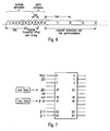
- Fig. 6 shows the structure of the known synchronization field.
- the synchronization field consists of so-called short symbols t1, t2, whilt6 and two long symbols T1, T2.
- the short symbols t1, t2....t6 are of interest.
- the short symbols t1, t2, ....t6 used for the amplifier gain control (t1, t2, t3) and the course frequency offset and timing control only the symbols t1, t2, t3 and t4 are actually generated, whereas the symbols t5, t6 are cyclic extensions (copies of the symbols t1 and t2, respectively). It is to be noted that fig.
- the symbols t1, t2, t3, t4 are generated by means of an OFDM modulation using selected subcarriers from the entire available subcarriers.
- the symbols used for the OFDM modulation as well as the mapping to the selected subcarriers will now be explained with reference to fig. 6 .
- the multiplication by a factor of ⁇ 2 is in order to normalize the average power of the resulting OFDM symbol.
- T TSHORT1 is equal to nine 0.8 ⁇ sec periods, i.e. 7.2 ⁇ sec.
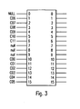
- the way to implement the inverse Fourier transform is by an IFFT (Inverse Fast Fourier Transform) algorithm. If, for example, a 64 point IFFT is used, the coefficients 1 to 24 are mapped to same numbered IFFT inputs, while the coefficients -24 to -1 are copied into IFFT inputs 40 to 63. The rest of the inputs, 25 to 39 and the 0 (DC) input, are set to zero. This mapping is illustrated in Fig. 7 . After performing an IFFT the output is cyclically extended to the desired length.
- IFFT Inverse Fast Fourier Transform
- the resulting time domain signal consists of 4 periodically repeated short symbols t1, t2, t3, t4, and cyclically extended by a copy of t1, t2, which copy is depicted in fig.5 as t5, t6.
- IFFT inverse fast Fourier transform
- PAPR Peak-to-Average-Power-Ratio
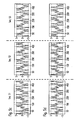
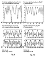
- Figures 8a, 8b show the "absolute" (sqrt ⁇ In*+Quad *Quad ⁇ ) value of the resulting time domain signal waveform with the sequences proposed by Lucent Technologies. Oversampling (8*) was considered in order to ensure the peak was captured correctly using the limited 64-point IFFT.
- Figures 8c, 8d show the real and imaginary part of the resulting transmitted time domain waveform.
- the resulting PAPR is 2.9991 dB (no oversampling) and 3.0093 dB (with 8 times oversampling).
- the symbol timing recovery proposed in this method relies on searching for a training symbol with two identical halves, which will remain identical after passing through the channel, except that there will be a phase difference between them caused by the carrier frequency offset.
- the two halves of the training symbol are made identical by transmitting a pseudo-noise (PN) sequence on the even frequencies, while zeros are used on the odd frequencies.
- PN pseudo-noise
- the second training symbol contains a PN sequence on the odd frequencies to measure the sub-channels, and another PN sequence on the even frequencies to help determine frequency offset.
- This paper uses PN sequences in the training sequence for an OFDM signal with eight subcarriers with the points chosen from a subset of a 64-QAM constellation comprising the points (+-7 +-7j) and (+-5 +-5j).
- WO 98/00946 A2 discloses a method for timing synchronization, carrier frequency synchronization, and sampling rate synchronization of a receiver to an OFDM signal.
- a training sequence is created on the basis of predetermined PN sequences.
- the sub-symbol values (+-7+-7j) and (+-5+-5j) are used respectively for the two OFDM training symbols.
- the values s 1 (t) and s 2 (t-T) denote non-overlapping wave forms and the paired burst to be transmitted have a constant envelope abs(s T (t)).
- a method for generating synchronization bursts for OFDM transmission systems is provided. Symbols of a predefined symbol sequence are mapped according to a predefined mapping scheme on subcarriers of the OFDM system wherein the symbols of the predefined symbol sequence represent subcarriers with nonzero amplitudes.
- a synchronization burst is generated by inverse fast Fourier transforming the subcarriers mapped with a predefined symbol sequence.
- the predefined symbol sequence is optimized such that the envelope fluctuation of the time domain signal (Peak-to-average-power-ratio) is minimized.
- mapping of the symbols of the predefined symbol sequence and the Inverse Fast Fourier Transform can be set such that the resulting time domain signal of the synchronization burst represents a periodic nature.
- mapping of the symbols of the predefined symbol sequence and the Inverse Fast Fourier Transform is set such that one burst part of the synchronization burst in the time domain is generated and the periodic nature of the synchronization burst in the time domain is achieved by copying the one burst part.
- the number of symbols of a symbol sequence (n) can for example be 12.
- the above equations define generally the symbol sequences according to the present invention.
- the predefined symbol sequence can therefore be for example: A A A -A -A -A -A A -A -A A -A, wherein A is a complex value.
- the predefined symbol sequence can be: A -A A A -A A A A A -A -A -A, wherein A is a complex value.
- a method for synchronizing wireless OFDM systems wherein a synchronization burst is generated according to a method as set forth above and the synchronization burst is transmitted respectively before the transmission of data fields.
- time domain signals of the synchronization burst can be precomputed and stored in a memory, such that the computation of the time domain signal of the burst is only effected once.
- a OFDM transmitter comprising a mapping unit for mapping the symbols of a predefined symbols sequence according to a predefmed mapping scheme on subcarriers of the OFDM system, wherein the symbols of a predefined symbols sequence represent the subcarriers of the OFDM system with nonzero amplitudes.
- an inverse fast Fourier transforming unit is provided for generating a synchronization burst by inverse fast Fourier transforming the subcarriers of the OFDM mapped with said predefined symbols sequence.
- the mapping unit thereby is designed such that the resulting time domain signal of the synchronization burst represents a periodic nature.
- the mapping unit according to the present invention uses a predefined symbol sequence which is such that the envelope fluctuation of the time domain signal of the synchronization burst is minimized.
- a mobile communications device such as set forth above is used.
- the time domain synchronization burst structure as shown in Fig. 6 is maintained.
- the IFFT mapping as shown in Fig. 7 can be maintained or alternatively the IFFT mapping according to figure 3 can be used.
- the symbol sequences mapped to the subcarriers are optimized to sequences which result in a lower PAPR.
- a short OFDM symbol (t1,...t6) consists of 12 phase-modulated subcarriers.
- the predefined symbol sequence therefore is chosen such that the envelope fluctuation of the time domain signal of the synchronization burst is minimized.
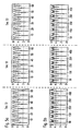
- Fig. 5a and 5b thereby show the time domain signal (magnitude) when using the optimized sequence according to the present invention in the case of no oversampling/8-times oversampling is effected.
- PAPR in decibel is limited to 2.059 (even when using a time domain oversampling to capture the actual peak).
- Fig. 5c and 5d show the in-phase and quadrature-phase component, respectively, of the resulting wave form. It is clearly visible that the full symbol consists of four repetitions of a short sequence.
- Fig. 5a to 5d show graphics corresponding to Fig. 4a to 4d for the other proposed sequences S1, S2 and S3.
- the PAPR is 3.01 dB and the dynamic range (defined as the ratio of the peak power to the minimum power) is 30.82 dB (see figures 9a and 9b ).
- the PAPR is reduced to 2.06 dB, however, the dynamic range is increased as the signal power is '0' at some points.
- the PAPR is reduced to 2.24 dB and the dynamic range is limited to 7.01 dB as it is shown in figures 10 a and 10b.
- the sync symbol data 1 are prepared and mapped in a IFFT mapping unit 2 to the appropriate IFFT points.
- the subcarriers of the OFDM system are transformed by a IFFT unit 3 and then the time domain signal is extended in a time extension unit 4 by copying parts of the signals (for example, t1, t2 are copied to t5, t6).
- the time extended signal is then sent to the I/Q modulator 5.
- the time domain signal can be precomputed once in a computation unit 7 and then be stored in a memory 6 for the precomputed sample for the time signal. Then the time domain signal of the synchronization burst can be sent to the modulator 5 directly from the memory 6.
- the IFFT size is now only 16 (instead of 64 as it is the case in figure 7 ). Only one of the bursts t1, t2, ....t6 will be generated. The other bursts can be generated by copying to retain the periodic nature of the synchronization time domain signal necessary for the correlation and synchronization on the receiving side. Therefore for example the time extension unit 4 can perform the copying of the 16-sample burst t1 generated by the IFFT 16 according to figure 7 to the other burst t2, t3, ...t6. Obviously the mapping scheme according to figure 3 reduces the computing effort necessary for the IFFT. The periodic nature of the time domain signal of the SYNCH bursts is therefore no longer achieved by the IFFT step, but by copying the burst t1 generated with the simplified IFFT mapping scheme.
- mapping scheme shown in figure 3 is also advantageous in combination with the precomputing technique shown in figure 2 .
- a synchronization burst structure to be used in high speed wireless transmission systems is proposed.
- the synchronization burst is constructed using especially designed OFDM symbols and time domain repetitions.
- the resulting synchronization burst achieves a high timing detection and frequency offset estimation accuracy.
- the burst is optimized to achieve a very low envelope fluctuation (Low peak-to-average-power-ratio) to reduce the complexity on the receiver and to reduce time and frequency acquisition time at the receiver.
- the synchronization performance can further be improved.
- the envelope of the OFDM based synchronization burst in the time domain is reduced, the AGC pool-in speed at the receiver can be improved and an accurate time and frequency synchronization can be achieved.
- the synchronization complexity on the receiver side can be reduced due to the reduced resolution requirements necessary due to reduced envelope fluctuation.
Landscapes
- Engineering & Computer Science (AREA)
- Signal Processing (AREA)
- Computer Networks & Wireless Communication (AREA)
- Power Engineering (AREA)
- Synchronisation In Digital Transmission Systems (AREA)
- Digital Transmission Methods That Use Modulated Carrier Waves (AREA)
- Mobile Radio Communication Systems (AREA)
Description
- The present invention relates to a method for generating synchronization bursts for OFDM transmission systems, a method for synchronizing wireless OFDM systems, an OFDM transmitter as well as to a mobile communications device comprising such a transmitter.
- The present invention relates generally to the technical field of synchronizing wireless OFDM (orthogonal frequency division multiplexing) systems. Thereby it is known to use a synchronization burst constructed using especially designed OFDM symbols and time domain repetitions.
- Particularly from the document IEEE P802.11a/d2.0 "Draft supplement to a standard for telecommunications and information exchange between systems - LAN/MAN specific requirements - part 1: wireless medium access control (MAC) and physical layer (PHY) specifications: high-speed physical layer in the 5 GHz band" a synchronization scheme for OFDM systems is proposed. This document is herewith included by reference as far as it concerns the synchronization including the proposed implementation. Said known scheme will now be explained with reference to
fig. 6 to 8 of the enclosed drawings. -
Fig. 6 shows the structure of the known synchronization field. As shown inFig. 6 the synchronization field consists of so-called short symbols t1, t2,.....t6 and two long symbols T1, T2. In view of the present invention particularly the short symbols t1, t2....t6 are of interest. Among the short symbols t1, t2, ....t6 used for the amplifier gain control (t1, t2, t3) and the course frequency offset and timing control only the symbols t1, t2, t3 and t4 are actually generated, whereas the symbols t5, t6 are cyclic extensions (copies of the symbols t1 and t2, respectively). It is to be noted thatfig. 5 shows only the synchronization preamble structure as the structure of the following signal field indicating the type of baseband modulation and the coding rate as well as the structure of further following data fields are not of interest in view of the present invention. For further details reference is made to said prior art document. - The symbols t1, t2, t3, t4 are generated by means of an OFDM modulation using selected subcarriers from the entire available subcarriers. The symbols used for the OFDM modulation as well as the mapping to the selected subcarriers will now be explained with reference to
fig. 6 . - Each of the short OFDM symbols t1, ....t6 is generated by using 12 modulated subcarriers phase-modulated by the elements of the symbol alphabet:

- The full sequence used for the OFDM modulation can be written as follows:

- The multiplication by a factor of √2 is in order to normalize the average power of the resulting OFDM symbol.
- The signal can be written as:

- The fact that only spectral lines of S-24, 24 with indices which are a multiple of 4 have nonzero amplitude results in a periodicity of TFFT/4=0.8µsec. The interval TTSHORT1 is equal to nine 0.8 µsec periods, i.e. 7.2 µsec.
- Applying a 64-point IFFT to the vector S, where the remaining 15 values are set to zero, four short training symbols t1, t2, t3, t4 (in the time domain) can be generated. The IFFT output is cyclically extended to result in 6 short symbols t1, t2, t3, ...t6. The mapping scheme is depicted in
fig. 7 . The so called virtual subcarriers are left unmodulated. - The way to implement the inverse Fourier transform is by an IFFT (Inverse Fast Fourier Transform) algorithm. If, for example, a 64 point IFFT is used, the
coefficients 1 to 24 are mapped to same numbered IFFT inputs, while the coefficients -24 to -1 are copied intoIFFT inputs 40 to 63. The rest of the inputs, 25 to 39 and the 0 (DC) input, are set to zero. This mapping is illustrated inFig. 7 . After performing an IFFT the output is cyclically extended to the desired length. - With the proposed inverse fast Fourier transform (IFFT) mapping as shown in
fig. 7 the resulting time domain signal consists of 4 periodically repeated short symbols t1, t2, t3, t4, and cyclically extended by a copy of t1, t2, which copy is depicted infig.5 as t5, t6. Note that in the present case only spectral lines with indices which are a multiple of 4 have nonzero amplitude. Other periodic natures can be generated by setting other multiples of the spectral lines to nonzero amplitudes. - Though the known synchronization scheme is very effective, it provides for disadvantage regarding the time domain signal properties.
- For OFDM (or in general multicarrier signals) the signal envelope fluctuation (named Peak-to-Average-Power-Ratio=PAPR) is of great concern. A large PAPR results in poor transmission (due to nonlinear distortion effects of the power amplifier) and other signal limiting components in the transmission system (e.g. limited dynamic range of the AD converter).
- For synchronization sequences it is even more desirable to have signals with a low PAPR in order to accelerate the receiver AGC (automatic gain control) locking and adjusting the reference signal value for the A/D converter (the whole dynamic range of the incoming signal should be covered by the A/D converter resolution without any overflow/underflow).
-
Figures 8a, 8b show the "absolute" (sqrt { In*+Quad *Quad}) value of the resulting time domain signal waveform with the sequences proposed by Lucent Technologies. Oversampling (8*) was considered in order to ensure the peak was captured correctly using the limited 64-point IFFT. -
Figures 8c, 8d show the real and imaginary part of the resulting transmitted time domain waveform. The resulting PAPR is 2.9991 dB (no oversampling) and 3.0093 dB (with 8 times oversampling). - The paper "Low-overhead, low-complexity burst synchronization for OFDM", by Schmidl and Cox, 1996, discloses a rapid synchronization method for an OFDM system using either a continuous transmission or a burst operation over a time-varying fading channel. The symbol timing recovery proposed in this method relies on searching for a training symbol with two identical halves, which will remain identical after passing through the channel, except that there will be a phase difference between them caused by the carrier frequency offset. The two halves of the training symbol are made identical by transmitting a pseudo-noise (PN) sequence on the even frequencies, while zeros are used on the odd frequencies. The second training symbol contains a PN sequence on the odd frequencies to measure the sub-channels, and another PN sequence on the even frequencies to help determine frequency offset. This paper uses PN sequences in the training sequence for an OFDM signal with eight subcarriers with the points chosen from a subset of a 64-QAM constellation comprising the points (+-7 +-7j) and (+-5 +-5j).
-
WO 98/00946 A2 - The paper "Carrier synchronization with CEPB-OFDM" by Dinis and Gusmao, 1997, discloses a constant envelope paired burst (CEPB) OFDM technique allowing the use of a single grossly non-linear amplifier in transmitters. The paper proposes a CEPB-OFDM scheme, according to which the complex envelope of each paired burst to be transmitted to the receiver can be written as sT(t)=s1(t)+s2(t-T), where s1(t)=s(t)+j.e(t) and s2(t)=s(t) j.e(t), s(t) being the complex envelope of a clipped version of the OFDM burst. The values s1(t) and s2(t-T) denote non-overlapping wave forms and the paired burst to be transmitted have a constant envelope abs(sT(t)).
- Therefore it is the object of the present invention to provide for a synchronization technique which bases on the known synchronization technique but which presents improved time domain signal properties to reduce the requirements for the hardware.
- The above object is achieved by means of the features of the independent claims. The dependent claims develop further the central idea of the present invention.
- According to the present invention therefore a method for generating synchronization bursts for OFDM transmission systems is provided. Symbols of a predefined symbol sequence are mapped according to a predefined mapping scheme on subcarriers of the OFDM system wherein the symbols of the predefined symbol sequence represent subcarriers with nonzero amplitudes. A synchronization burst is generated by inverse fast Fourier transforming the subcarriers mapped with a predefined symbol sequence. According to the present invention the predefined symbol sequence is optimized such that the envelope fluctuation of the time domain signal (Peak-to-average-power-ratio) is minimized.
- The predefined symbol sequence can be chosen such that the following equations are satisfied for all symbols of the predefined symbol sequence:


- n being the number of symbols of the predefined symbol sequence,
- m being an integer larger than one,
- C being the symbol value, and
- i being an integer running from 1 to m.
- The mapping of the symbols of the predefined symbol sequence and the Inverse Fast Fourier Transform can be set such that the resulting time domain signal of the synchronization burst represents a periodic nature.
- Alternatively the mapping of the symbols of the predefined symbol sequence and the Inverse Fast Fourier Transform is set such that one burst part of the synchronization burst in the time domain is generated and the periodic nature of the synchronization burst in the time domain is achieved by copying the one burst part.
- The number of symbols of a symbol sequence (n) can for example be 12.
- The above equations define generally the symbol sequences according to the present invention. The predefined symbol sequence can therefore be for example:
A A A -A -A -A -A A -A -A A -A,
wherein A is a complex value. - Alternatively the predefined symbol sequence can be:
A -A A A -A A A A A -A -A -A,
wherein A is a complex value. - Alternatively the following predefined symbol sequence can be used:
A B -A B -A -B B A -B A -B -A,
wherein A, B are complex values. - As a further alternative the following sequence can be used:
A -B -A -B -A B -B A B A B -A,
wherein A, B are complex values. - According to the present invention furthermore a method for synchronizing wireless OFDM systems is provided, wherein a synchronization burst is generated according to a method as set forth above and the synchronization burst is transmitted respectively before the transmission of data fields.
- Thereby the time domain signals of the synchronization burst can be precomputed and stored in a memory, such that the computation of the time domain signal of the burst is only effected once.
- According to the present invention furthermore a OFDM transmitter is provided comprising a mapping unit for mapping the symbols of a predefined symbols sequence according to a predefmed mapping scheme on subcarriers of the OFDM system, wherein the symbols of a predefined symbols sequence represent the subcarriers of the OFDM system with nonzero amplitudes. Furthermore an inverse fast Fourier transforming unit is provided for generating a synchronization burst by inverse fast Fourier transforming the subcarriers of the OFDM mapped with said predefined symbols sequence. The mapping unit thereby is designed such that the resulting time domain signal of the synchronization burst represents a periodic nature. The mapping unit according to the present invention uses a predefined symbol sequence which is such that the envelope fluctuation of the time domain signal of the synchronization burst is minimized.
- According to the present invention furthermore a mobile communications device such as set forth above is used.
- With reference to the figures of the enclosed drawings referred embodiments of the present invention will now be explained.
-
Fig. 1 shows schematically a transmitter according to the present invention, -
Fig. 2 shows an alternative embodiment for a transmitter according to the present invention, -
Fig.3 shows an alternative mapping scheme according to the present invention, -
Fig. 4a to 4d show the time domain signal properties achieved with the synchronization symbol structure using OFDM based transmission according to the present invention, -
Fig. 5a to 5d show the time domain signal properties of synchronization symbol structures according to alternative embodiments of the present invention, -
Fig. 6 shows a synchronization preamble structure known from the prior art, -
Fig. 7 shows an IFFT mapping according to the prior art, and -
Fig. 8a to 8d show the time domain properties of the synchronization symbol structure according to the prior art, -
Fig. 9a and 9b show the time domain properties, particularly the dynamic range of the synchronization symbol structure according to the prior art, and -
Fig. 10a and 10b show the time domain properties of the synchronization symbol structure according to further alternative embodiments of the present invention, - According to the present invention the time domain synchronization burst structure as shown in
Fig. 6 is maintained. The IFFT mapping as shown inFig. 7 can be maintained or alternatively the IFFT mapping according tofigure 3 can be used. The symbol sequences mapped to the subcarriers are optimized to sequences which result in a lower PAPR. - According to the present invention a short OFDM symbol (t1,...t6) consists of 12 phase-modulated subcarriers.
C00 C01 C02 C03 C04 C05 C06 C07 C08 C09 C10 C11 Seq0 A A A -A -A -A -A A -A -A A -A Seq1 A -A A A -A A A A A -A -A -A Seq2 A B -A B -A -B B A -B A -B -A Seq3 A -B -A -B -A B -B A B A B -A 
- Generally the predefined symbol sequence therefore is chosen such that the envelope fluctuation of the time domain signal of the synchronization burst is minimized.
- Therefore generally the predefined symbol sequence is set such that the following equations are satisfied for all symbols for the predefined symbol sequence:


- n is a number of symbols of the predefined symbol sequence,
- m is an integer larger than 1,
- c is the symbol value, and
- i is an integer value running from 1 to m.
- In the following the time domain signal properties of the new sequences according to the present invention will be shown with reference to
Fig. 4a to 4d andFig. 5a to 5d . - For simplicity we use in our demonstration the classical quadriphase symbol alphabet,

Table 1: Complex symbol mapping Symbol A 

-A 

B 

-B 

-
Fig. 5a and 5b thereby show the time domain signal (magnitude) when using the optimized sequence according to the present invention in the case of no oversampling/8-times oversampling is effected. - PAPR (in decibel) is limited to 2.059 (even when using a time domain oversampling to capture the actual peak).
-
Fig. 5c and 5d show the in-phase and quadrature-phase component, respectively, of the resulting wave form. It is clearly visible that the full symbol consists of four repetitions of a short sequence. -
Fig. 5a to 5d show graphics corresponding toFig. 4a to 4d for the other proposed sequences S1, S2 and S3. - Further simulations have shown that not only the PAPR can be optimized but also the dynamic range of the signal should be minimized. Therefore another four sequences, with achieve a small PAPR and at the same time a small overall dynamic range are proposed further below.
- Using the sequence as proposed in the state of the art the PAPR is 3.01 dB and the dynamic range (defined as the ratio of the peak power to the minimum power) is 30.82 dB (see
figures 9a and 9b ). - Using the sequences according to the present invention and as described above the PAPR is reduced to 2.06 dB, however, the dynamic range is increased as the signal power is '0' at some points.
- Therefore the following four sequences are proposed as a further embodiment of the present invention:
- The symbol sequence is C0, C1, .... , C11 and the mapping is:
S=2* { C00, 0, 0, 0, C01, 0, 0, 0, C02, 0, 0, 0, C03, 0, 0, 0, C04, 0, 0, 0, C05, 0, 0, 0, 0, 0, 0, 0, C06, 0, 0, 0, C07, 0, 0, 0, C08, 0, 0, 0, C09, 0, 0, 0, C10, 0, 0, 0, C11 }C00 C01 C02 C03 C04 C05 C06 C07 C08 C09 C10 C11 Seq-Alt0 A A A A -A -A A -A -A A -A A Seq-Alt1 A -A A -A -A A -A -A A A A A Seq-Alt2 A B -A -B -A -B -B -A -B -A B A Seq-Alt3 A -B -A B -A B B -A B -A -B A 
- Using these sequences the PAPR is reduced to 2.24 dB and the dynamic range is limited to 7.01 dB as it is shown in
figures 10 a and 10b. - The advantages are the same as described before, however, the clipping problem is further reduced due to the very limited dynamic range of the signal.
- With reference to
Fig. 1 and 2 possible implementations of a transmitter according to the present invention will now be explained. - In the transmitter the
sync symbol data 1 are prepared and mapped in aIFFT mapping unit 2 to the appropriate IFFT points. The subcarriers of the OFDM system are transformed by aIFFT unit 3 and then the time domain signal is extended in atime extension unit 4 by copying parts of the signals (for example, t1, t2 are copied to t5, t6). The time extended signal is then sent to the I/Q modulator 5. - As shown in
Fig. 2 alternatively the time domain signal can be precomputed once in acomputation unit 7 and then be stored in amemory 6 for the precomputed sample for the time signal. Then the time domain signal of the synchronization burst can be sent to themodulator 5 directly from thememory 6. - With reference to
figure 3 a modified IFFT mapping scheme will now be explained. According to this scheme, the principle of setting only every fourth subcarrier of the OFDM system to a non-zero amplitude (seefigure 7 ) is abandoned. Therefore the time domain signal achieved according to the mapping scheme offigure 3 will not present a periodic nature. - The IFFT size is now only 16 (instead of 64 as it is the case in
figure 7 ). Only one of the bursts t1, t2, ....t6 will be generated. The other bursts can be generated by copying to retain the periodic nature of the synchronization time domain signal necessary for the correlation and synchronization on the receiving side. Therefore for example thetime extension unit 4 can perform the copying of the 16-sample burst t1 generated by theIFFT 16 according tofigure 7 to the other burst t2, t3, ...t6. Obviously the mapping scheme according tofigure 3 reduces the computing effort necessary for the IFFT. The periodic nature of the time domain signal of the SYNCH bursts is therefore no longer achieved by the IFFT step, but by copying the burst t1 generated with the simplified IFFT mapping scheme. - The mapping scheme shown in
figure 3 is also advantageous in combination with the precomputing technique shown infigure 2 . - According to the present invention therefore a synchronization burst structure to be used in high speed wireless transmission systems is proposed. The synchronization burst is constructed using especially designed OFDM symbols and time domain repetitions. The resulting synchronization burst achieves a high timing detection and frequency offset estimation accuracy. Furthermore the burst is optimized to achieve a very low envelope fluctuation (Low peak-to-average-power-ratio) to reduce the complexity on the receiver and to reduce time and frequency acquisition time at the receiver.
- Therefore the synchronization performance can further be improved. As with the scheme according to the present invention the envelope of the OFDM based synchronization burst in the time domain is reduced, the AGC pool-in speed at the receiver can be improved and an accurate time and frequency synchronization can be achieved. Furthermore the synchronization complexity on the receiver side can be reduced due to the reduced resolution requirements necessary due to reduced envelope fluctuation.
- The advantages of the present invention can be set forth as following:
- An OFDM based SYNCH symbol with a reduced Peak-to-Average-Power-Ratio (PARP) is proposed,
- Improved synchronization performance (compared to the state of the art proposal),
- Reduced AGC (automatic gain control) pull-in time due to reduced dynamic range of the SYNCH burst,
- Improved AGC settlement (AGC has to adjust to a incoming signal level that later on now overflow/underflow in the AD happens. The reduced dynamic range of the SYNCH burst help to find this reference level more accurate),
- Reduced synchronization detection complexity on the receiver (reduced resolution necessary due to reduced envelope fluctuation).
Claims (4)
- A method for generating a signal for a frequency synchronisation of OFDM systems,
the method comprising the following steps:- in the frequency domain, mapping (2) the symbols of a predefined symbol sequence according to a defined mapping scheme on sub-carriers S of the OFDM system, wherein in the symbols C0, ..., C11 of the symbol sequence define the sub-carriers of the OFDM system with non-zero amplitude, and- generating the time-domain synchronisation signal by inverse Fourier transforming (3) the sub-carriers S of the OFDM system mapped with the symbols of the symbol sequence,wherein the symbol sequence comprises twelve symbols C0, ..., C11 being binary values represented by sqrt(1/2).(1+j) or sqrt(1/2).(-1-j). - A telecommunication device designed to carry out the method according to claim 1.
- An OFDM system, comprising a transmitter and a receiver, the transmitter being designed to transmit a signal generated according to the method of claim 1 in order to synchronize the receiver.
- A method for the frequency synchronization of an OFDM transmitter, comprising the steps of transmitting, receiving and auto-correlating a signal generated according to the method of claim 1.
Priority Applications (4)
| Application Number | Priority Date | Filing Date | Title |
|---|---|---|---|
| EP09160351A EP2088728B1 (en) | 1999-02-22 | 1999-02-22 | Synchronization preamble structure for OFDM system |
| EP09160346A EP2088727B1 (en) | 1999-02-22 | 1999-02-22 | Synchronisation symbol structure for OFDM system |
| AT09160351T ATE496471T1 (en) | 1999-02-22 | 1999-02-22 | SYNCHRONIZATION ATTACHMENT STRUCTURE FOR OFDM SYSTEM |
| EP05002279A EP1530336B1 (en) | 1999-01-08 | 1999-02-22 | Synchronization preamble structure for OFDM system |
Applications Claiming Priority (5)
| Application Number | Priority Date | Filing Date | Title |
|---|---|---|---|
| EP99100263 | 1999-01-08 | ||
| EP99100263 | 1999-01-08 | ||
| EP99103379A EP1018827B1 (en) | 1999-01-08 | 1999-02-22 | Synchronisation structure for OFDM system |
| EP04002920A EP1439677B9 (en) | 1999-01-08 | 1999-02-22 | Synchronisation symbol structure for an OFDM system |
| EP05002279A EP1530336B1 (en) | 1999-01-08 | 1999-02-22 | Synchronization preamble structure for OFDM system |
Related Parent Applications (3)
| Application Number | Title | Priority Date | Filing Date |
|---|---|---|---|
| EP99103379.6 Division | 1999-02-22 | ||
| EP04002920A Division EP1439677B9 (en) | 1999-01-08 | 1999-02-22 | Synchronisation symbol structure for an OFDM system |
| EP04002920.9 Division | 2004-02-10 |
Related Child Applications (2)
| Application Number | Title | Priority Date | Filing Date |
|---|---|---|---|
| EP09160351A Division EP2088728B1 (en) | 1999-01-08 | 1999-02-22 | Synchronization preamble structure for OFDM system |
| EP09160346A Division EP2088727B1 (en) | 1999-02-22 | 1999-02-22 | Synchronisation symbol structure for OFDM system |
Publications (2)
| Publication Number | Publication Date |
|---|---|
| EP1530336A1 EP1530336A1 (en) | 2005-05-11 |
| EP1530336B1 true EP1530336B1 (en) | 2009-06-10 |
Family
ID=26152852
Family Applications (5)
| Application Number | Title | Priority Date | Filing Date |
|---|---|---|---|
| EP06014694A Expired - Lifetime EP1705852B1 (en) | 1999-01-08 | 1999-02-22 | Synchronisation symbol structure for OFDM system |
| EP06014693A Expired - Lifetime EP1722527B1 (en) | 1999-01-08 | 1999-02-22 | Synchronisation symbol structure for OFDM system |
| EP04002920A Expired - Lifetime EP1439677B9 (en) | 1999-01-08 | 1999-02-22 | Synchronisation symbol structure for an OFDM system |
| EP05002279A Expired - Lifetime EP1530336B1 (en) | 1999-01-08 | 1999-02-22 | Synchronization preamble structure for OFDM system |
| EP99103379A Expired - Lifetime EP1018827B1 (en) | 1999-01-08 | 1999-02-22 | Synchronisation structure for OFDM system |
Family Applications Before (3)
| Application Number | Title | Priority Date | Filing Date |
|---|---|---|---|
| EP06014694A Expired - Lifetime EP1705852B1 (en) | 1999-01-08 | 1999-02-22 | Synchronisation symbol structure for OFDM system |
| EP06014693A Expired - Lifetime EP1722527B1 (en) | 1999-01-08 | 1999-02-22 | Synchronisation symbol structure for OFDM system |
| EP04002920A Expired - Lifetime EP1439677B9 (en) | 1999-01-08 | 1999-02-22 | Synchronisation symbol structure for an OFDM system |
Family Applications After (1)
| Application Number | Title | Priority Date | Filing Date |
|---|---|---|---|
| EP99103379A Expired - Lifetime EP1018827B1 (en) | 1999-01-08 | 1999-02-22 | Synchronisation structure for OFDM system |
Country Status (5)
| Country | Link |
|---|---|
| US (8) | US6654339B1 (en) |
| EP (5) | EP1705852B1 (en) |
| JP (1) | JP4050437B2 (en) |
| KR (1) | KR100712865B1 (en) |
| CA (1) | CA2291847C (en) |
Families Citing this family (64)
| Publication number | Priority date | Publication date | Assignee | Title |
|---|---|---|---|---|
| EP1705852B1 (en) | 1999-01-08 | 2010-02-10 | Sony Deutschland Gmbh | Synchronisation symbol structure for OFDM system |
| EP1416694B1 (en) | 1999-06-16 | 2006-09-20 | Sony Deutschland GmbH | Optimized synchronization preamble structure for OFDM system |
| EP2262157A3 (en) * | 2000-07-05 | 2011-03-23 | Sony Deutschland Gmbh | Pilot pattern design for a STTD scheme in an OFDM system |
| US9130810B2 (en) | 2000-09-13 | 2015-09-08 | Qualcomm Incorporated | OFDM communications methods and apparatus |
| US7295509B2 (en) | 2000-09-13 | 2007-11-13 | Qualcomm, Incorporated | Signaling method in an OFDM multiple access system |
| US6754170B1 (en) * | 2000-09-29 | 2004-06-22 | Symbol Technologies, Inc. | Timing synchronization in OFDM communications receivers |
| US6950475B1 (en) * | 2000-12-11 | 2005-09-27 | Cisco Technology, Inc. | OFDM receiver clock synchronization system |
| DE60320956D1 (en) * | 2002-03-07 | 2008-06-26 | Alvarion Ltd | HIERARCHICAL PREAMBLE STRUCTURES FOR OFDMA BASED ON COMPLEMENTARY SEQUENCES |
| US20040066740A1 (en) * | 2002-09-30 | 2004-04-08 | Samsung Electronics Co., Ltd. | Apparatus and method for generating preamble sequence in a OFDM communication system |
| WO2004039026A1 (en) * | 2002-10-23 | 2004-05-06 | Samsung Electronics Co., Ltd. | Apparatus and method for generating a preamble sequence in an ofdm communication system |
| WO2004051901A1 (en) * | 2002-11-30 | 2004-06-17 | Samsung Electronics Co., Ltd. | Apparatus and method for generating a preamble sequence in an ofdm communication system |
| KR100905572B1 (en) * | 2002-12-03 | 2009-07-02 | 삼성전자주식회사 | Apparatus and method for generating preamble sequence in communication system using orthogonal frequency division multiplexing |
| US7567639B2 (en) | 2004-04-28 | 2009-07-28 | Samsung Electronics Co., Ltd | Method and apparatus for generating preamble sequence for adaptive antenna system in orthogonal frequency division multiple access communication system |
| US9137822B2 (en) | 2004-07-21 | 2015-09-15 | Qualcomm Incorporated | Efficient signaling over access channel |
| US9148256B2 (en) | 2004-07-21 | 2015-09-29 | Qualcomm Incorporated | Performance based rank prediction for MIMO design |
| US7961828B2 (en) * | 2004-10-06 | 2011-06-14 | Motorola Mobility, Inc. | Sync bursts frequency offset compensation |
| CN1780276B (en) * | 2004-11-25 | 2012-01-04 | 都科摩(北京)通信技术研究中心有限公司 | Combined time synchronizing and frequency bias evaluation and evaluating device for orthogonal frequency division duplex system |
| US9246560B2 (en) | 2005-03-10 | 2016-01-26 | Qualcomm Incorporated | Systems and methods for beamforming and rate control in a multi-input multi-output communication systems |
| US9154211B2 (en) | 2005-03-11 | 2015-10-06 | Qualcomm Incorporated | Systems and methods for beamforming feedback in multi antenna communication systems |
| US8446892B2 (en) | 2005-03-16 | 2013-05-21 | Qualcomm Incorporated | Channel structures for a quasi-orthogonal multiple-access communication system |
| US9143305B2 (en) | 2005-03-17 | 2015-09-22 | Qualcomm Incorporated | Pilot signal transmission for an orthogonal frequency division wireless communication system |
| US9461859B2 (en) | 2005-03-17 | 2016-10-04 | Qualcomm Incorporated | Pilot signal transmission for an orthogonal frequency division wireless communication system |
| US9520972B2 (en) | 2005-03-17 | 2016-12-13 | Qualcomm Incorporated | Pilot signal transmission for an orthogonal frequency division wireless communication system |
| JP4429945B2 (en) | 2005-03-23 | 2010-03-10 | 株式会社エヌ・ティ・ティ・ドコモ | MIMO multiplex communication apparatus and signal separation method |
| US9184870B2 (en) | 2005-04-01 | 2015-11-10 | Qualcomm Incorporated | Systems and methods for control channel signaling |
| US9408220B2 (en) | 2005-04-19 | 2016-08-02 | Qualcomm Incorporated | Channel quality reporting for adaptive sectorization |
| US9036538B2 (en) | 2005-04-19 | 2015-05-19 | Qualcomm Incorporated | Frequency hopping design for single carrier FDMA systems |
| US8565194B2 (en) | 2005-10-27 | 2013-10-22 | Qualcomm Incorporated | Puncturing signaling channel for a wireless communication system |
| US8611284B2 (en) | 2005-05-31 | 2013-12-17 | Qualcomm Incorporated | Use of supplemental assignments to decrement resources |
| US8879511B2 (en) | 2005-10-27 | 2014-11-04 | Qualcomm Incorporated | Assignment acknowledgement for a wireless communication system |
| US8462859B2 (en) | 2005-06-01 | 2013-06-11 | Qualcomm Incorporated | Sphere decoding apparatus |
| US8599945B2 (en) | 2005-06-16 | 2013-12-03 | Qualcomm Incorporated | Robust rank prediction for a MIMO system |
| US9179319B2 (en) | 2005-06-16 | 2015-11-03 | Qualcomm Incorporated | Adaptive sectorization in cellular systems |
| JP4563453B2 (en) * | 2005-08-03 | 2010-10-13 | 国立大学法人 奈良先端科学技術大学院大学 | Transmitter and receiver |
| US8885628B2 (en) | 2005-08-08 | 2014-11-11 | Qualcomm Incorporated | Code division multiplexing in a single-carrier frequency division multiple access system |
| US9209956B2 (en) | 2005-08-22 | 2015-12-08 | Qualcomm Incorporated | Segment sensitive scheduling |
| US20070041457A1 (en) | 2005-08-22 | 2007-02-22 | Tamer Kadous | Method and apparatus for providing antenna diversity in a wireless communication system |
| US8644292B2 (en) | 2005-08-24 | 2014-02-04 | Qualcomm Incorporated | Varied transmission time intervals for wireless communication system |
| US9136974B2 (en) | 2005-08-30 | 2015-09-15 | Qualcomm Incorporated | Precoding and SDMA support |
| US9088384B2 (en) | 2005-10-27 | 2015-07-21 | Qualcomm Incorporated | Pilot symbol transmission in wireless communication systems |
| US9225488B2 (en) | 2005-10-27 | 2015-12-29 | Qualcomm Incorporated | Shared signaling channel |
| US8045512B2 (en) | 2005-10-27 | 2011-10-25 | Qualcomm Incorporated | Scalable frequency band operation in wireless communication systems |
| US8582509B2 (en) | 2005-10-27 | 2013-11-12 | Qualcomm Incorporated | Scalable frequency band operation in wireless communication systems |
| US8477684B2 (en) | 2005-10-27 | 2013-07-02 | Qualcomm Incorporated | Acknowledgement of control messages in a wireless communication system |
| US8693405B2 (en) | 2005-10-27 | 2014-04-08 | Qualcomm Incorporated | SDMA resource management |
| US9172453B2 (en) | 2005-10-27 | 2015-10-27 | Qualcomm Incorporated | Method and apparatus for pre-coding frequency division duplexing system |
| US9144060B2 (en) | 2005-10-27 | 2015-09-22 | Qualcomm Incorporated | Resource allocation for shared signaling channels |
| US9225416B2 (en) | 2005-10-27 | 2015-12-29 | Qualcomm Incorporated | Varied signaling channels for a reverse link in a wireless communication system |
| US9210651B2 (en) | 2005-10-27 | 2015-12-08 | Qualcomm Incorporated | Method and apparatus for bootstraping information in a communication system |
| US8582548B2 (en) | 2005-11-18 | 2013-11-12 | Qualcomm Incorporated | Frequency division multiple access schemes for wireless communication |
| US8831607B2 (en) | 2006-01-05 | 2014-09-09 | Qualcomm Incorporated | Reverse link other sector communication |
| CN1852281B (en) * | 2006-01-23 | 2010-06-09 | 北京邮电大学 | A Synchronization Method for Orthogonal Frequency Division Multiple Access System |
| US7983143B2 (en) | 2006-02-08 | 2011-07-19 | Motorola Mobility, Inc. | Method and apparatus for initial acquisition and cell search for an OFDMA system |
| US7911935B2 (en) * | 2006-02-08 | 2011-03-22 | Motorola Mobility, Inc. | Method and apparatus for interleaving sequence elements of an OFDMA synchronization channel |
| DE602006005606D1 (en) * | 2006-03-20 | 2009-04-23 | Fujitsu Ltd | Symbol for subcarrier assignment in OFDM communication systems and procedures |
| JP2007259445A (en) | 2006-03-20 | 2007-10-04 | Fujitsu Ltd | Transmission apparatus and method in OFDM communication system |
| CN101022438B (en) * | 2006-03-30 | 2011-12-14 | 北京新岸线移动通信技术有限公司 | Compatible DAB digital broadcasting receiver carrier synchronizing method and system |
| PL2090050T5 (en) | 2007-05-02 | 2018-02-28 | Huawei Technologies Co., Ltd. | Method and apparatus of establishing a synchronisation signal in a communication system |
| CN101083508B (en) * | 2007-07-19 | 2010-06-02 | 清华大学 | Performance test method of OFDM modulation system based on sequence transmission with low peak-to-valley ratio |
| CN101420411B (en) * | 2008-12-05 | 2011-02-09 | 航天恒星科技有限公司 | A Fast Acquisition Method for Low SNR Carriers |
| CN106685876B (en) * | 2016-11-14 | 2021-08-10 | 西南石油大学 | Multi-dimensional PTS method for reducing peak-to-average power ratio of OFDM system |
| ES2895680T3 (en) * | 2017-11-07 | 2022-02-22 | Siemens Ag | Procedure for the synchronization of transmitting and receiving units in a multicarrier signal transmission |
| CN110535795B (en) * | 2018-05-24 | 2021-11-05 | 中兴通讯股份有限公司 | A signal processing method and device |
| CN113315730B (en) * | 2021-05-24 | 2022-12-27 | 扬州大学 | Time-frequency synchronization method based on filter multi-carrier system |
Family Cites Families (58)
| Publication number | Priority date | Publication date | Assignee | Title |
|---|---|---|---|---|
| US5450456A (en) * | 1993-11-12 | 1995-09-12 | Daimler Benz Ag | Method and arrangement for measuring the carrier frequency deviation in a multi-channel transmission system |
| US5732113A (en) * | 1996-06-20 | 1998-03-24 | Stanford University | Timing and frequency synchronization of OFDM signals |
| EP0836303B1 (en) * | 1996-10-14 | 2003-02-26 | Ntt Mobile Communications Network Inc. | Method and apparatus for reduction of peak to average power ratio |
| GB9625094D0 (en) * | 1996-12-03 | 1997-01-22 | Ensigma Ltd | Apparatus and methods for measuring coarse frequency offset of a multi-carrier signal |
| US5990176A (en) | 1997-01-27 | 1999-11-23 | Abbott Laboratories | Fluoroether compositions and methods for inhibiting their degradation in the presence of a Lewis acid |
| US6005840A (en) * | 1997-04-01 | 1999-12-21 | Lucent Technologies Inc. | Complementary encoding and modulation system for use in an orthogonal frequency division multiplexing transmitter system and method thereof |
| DE19733825A1 (en) * | 1997-08-05 | 1999-02-11 | Siemens Ag | Method and arrangement for combined measurement of the start of a data block and the carrier frequency offset in a multicarrier transmission system for irregular transmission of data blocks |
| EP0899923A1 (en) | 1997-08-29 | 1999-03-03 | Sony International (Europe) GmbH | Transmission of power control signals in a multicarrier modulation system |
| EP0901256B1 (en) | 1997-09-04 | 2006-11-29 | Sony Deutschland GmbH | Transmission system for OFDM-signals with optimized synchronisation |
| DE69737353T2 (en) | 1997-11-05 | 2007-11-29 | Sony Deutschland Gmbh | Synchronization in digital communication systems |
| DE69733313T2 (en) | 1997-11-07 | 2006-01-19 | Sony International (Europe) Gmbh | Multi-carrier transmission, compatible with the existing GSM system |
| JP4064473B2 (en) | 1997-12-18 | 2008-03-19 | ソニー インターナショナル(ヨーロッパ)ゲゼルシャフト ミット ベシュレンクテル ハフツング | n-port direct receiver |
| ES2524196T3 (en) | 1998-02-13 | 2014-12-04 | Thomson Licensing | Transmission method and transmitter |
| EP0938193A1 (en) | 1998-02-18 | 1999-08-25 | Sony International (Europe) GmbH | Header structure for TDD systems |
| EP0939527B1 (en) | 1998-02-18 | 2007-12-05 | Sony Deutschland GmbH | Mapping of multicarrier signals into GSM time slots |
| EP0938208A1 (en) | 1998-02-22 | 1999-08-25 | Sony International (Europe) GmbH | Multicarrier transmission, compatible with the existing GSM system |
| US6470055B1 (en) * | 1998-08-10 | 2002-10-22 | Kamilo Feher | Spectrally efficient FQPSK, FGMSK, and FQAM for enhanced performance CDMA, TDMA, GSM, OFDN, and other systems |
| EP0982905B1 (en) | 1998-08-28 | 2005-08-10 | Sony International (Europe) GmbH | Universal PSK modulation apparatus and method |
| EP0984595B1 (en) | 1998-09-03 | 2007-04-25 | Sony Deutschland GmbH | Blind modulation detection |
| EP0984596A1 (en) | 1998-09-03 | 2000-03-08 | Sony International (Europe) GmbH | Adpative PSK system and timing offset compensation circuit |
| EP0987863B1 (en) | 1998-09-17 | 2005-04-06 | Sony International (Europe) GmbH | Soft decision method and apparatus for 8PSK demodulation |
| US6452987B1 (en) * | 1998-11-25 | 2002-09-17 | Lucent Technologies Inc. | Fast start-up in discrete multi-tone (DMT) based communications system |
| EP1006668B1 (en) | 1998-11-30 | 2011-01-05 | Sony Deutschland GmbH | Dual frequency band transceiver |
| EP1009098A1 (en) | 1998-12-10 | 2000-06-14 | Sony International (Europe) GmbH | Error correction using a turbo code and a CRC |
| EP1011204B1 (en) | 1998-12-18 | 2005-04-13 | Sony International (Europe) GmbH | Three-port junction receiver |
| EP1705852B1 (en) | 1999-01-08 | 2010-02-10 | Sony Deutschland Gmbh | Synchronisation symbol structure for OFDM system |
| DE69942398D1 (en) | 1999-02-24 | 2010-07-01 | Sony Deutschland Gmbh | Receiving device and synchronization method for a digital communication system |
| US8861622B2 (en) | 1999-02-24 | 2014-10-14 | Sony Deutschland Gmbh | Transmitting apparatus and method for a digital telecommunication system |
| EP1039661A1 (en) | 1999-03-03 | 2000-09-27 | Sony International (Europe) GmbH | Multicast channel for a CDMA system |
| EP1037481A1 (en) | 1999-03-15 | 2000-09-20 | Sony International (Europe) GmbH | Simultaneous transmission of random access bursts |
| ES2198811T3 (en) | 1999-04-12 | 2004-02-01 | Sony International (Europe) Gmbh | COMMUNICATION AND PROCEDURE DEVICE FOR DISTINGUISHING BETWEEN DIFFERENT TYPES OF GUSTS IN A DIGITAL TELECOMMUNICATIONS SYSTEM. |
| DE69932150T2 (en) | 1999-04-23 | 2006-11-09 | Sony Deutschland Gmbh | Synchronization preamble in an OFDM system |
| DE69924978T2 (en) | 1999-05-27 | 2006-02-02 | Sony International (Europe) Gmbh | Down-converter and demodulator with a three-port circuit arrangement |
| EP1061660B1 (en) | 1999-06-16 | 2006-08-09 | Sony Deutschland GmbH | N-port receiver with RF/LO isolation |
| EP1416694B1 (en) | 1999-06-16 | 2006-09-20 | Sony Deutschland GmbH | Optimized synchronization preamble structure for OFDM system |
| EP1065855A1 (en) | 1999-06-29 | 2001-01-03 | Sony International (Europe) GmbH | Adaptation of cyclic extensions in an OFDM communication system |
| DE69924989T2 (en) | 1999-07-08 | 2006-02-23 | Sony International (Europe) Gmbh | Calibration of a receiver with N-gates |
| EP1067705B1 (en) | 1999-07-09 | 2009-08-26 | Sony Deutschland GmbH | Cell coverage extension in downlink power controlled radio communication systems |
| DE69926064T2 (en) | 1999-09-29 | 2006-04-13 | Sony International (Europe) Gmbh | Three-port structure with modulated injection signal |
| KR20000000479A (en) * | 1999-10-27 | 2000-01-15 | 신창우 | Skin for wig |
| DE60005291T2 (en) | 2000-01-24 | 2004-07-15 | Sony International (Europe) Gmbh | Structure and method for demodulation |
| US7106821B2 (en) | 2000-03-15 | 2006-09-12 | Sony Corporation | Data modulation method, data modulation device and communication device |
| EP1162764B1 (en) | 2000-06-05 | 2007-08-15 | Sony Deutschland GmbH | Indoor wireless system using active reflector |
| DE60032593T2 (en) | 2000-07-05 | 2007-10-04 | Sony Deutschland Gmbh | Channel estimator for an OFDM system |
| DE60031105T2 (en) | 2000-07-06 | 2007-04-05 | Sony Deutschland Gmbh | Method and apparatus for providing uplink IFDM with time-frequency interleaving |
| DE60028200T2 (en) | 2000-08-01 | 2007-03-15 | Sony Deutschland Gmbh | Device and method for channel estimation for OFDM system |
| DE60035683T2 (en) | 2000-08-01 | 2008-06-26 | Sony Deutschland Gmbh | Frequency reuse scheme for OFDM systems |
| EP1207662B1 (en) | 2000-11-20 | 2003-09-17 | Sony International (Europe) GmbH | OFDM system with antenna diversity in the transmitter and pre-equalisation |
| EP2259480A3 (en) | 2000-11-20 | 2012-05-02 | Sony Deutschland Gmbh | Adaptive subcarrier loading |
| US6407846B1 (en) * | 2001-03-16 | 2002-06-18 | All Optical Networks, Inc. | Photonic wavelength shifting method |
| ES2278661T3 (en) | 2001-07-10 | 2007-08-16 | Sony Deutschland Gmbh | REFERENCE SYMBOLS FOR THE ESTIMATION OF CHANNELS WITH MULTIPORT CARRIAGE. |
| DE60144162D1 (en) | 2001-07-11 | 2011-04-14 | Sony Deutschland Gmbh | Method for calculating a weight vector for a group antenna |
| US7037527B2 (en) | 2002-01-25 | 2006-05-02 | University Of Rhode Island | Bifunctionalized polyester material for surface treatment and biomodification |
| EP1379026A1 (en) | 2002-07-03 | 2004-01-07 | Sony International (Europe) GmbH | Dual rate wireless transmission system |
| EP1545069A1 (en) | 2003-12-19 | 2005-06-22 | Sony International (Europe) GmbH | Remote polling and control system |
| EP1596504B1 (en) | 2004-05-11 | 2007-03-14 | Sony Deutschland GmbH | Pole switch down converter with symmetric resonator |
| EP1630713B1 (en) | 2004-08-24 | 2020-05-20 | Sony Deutschland GmbH | Backscatter interrogator reception method and interrogator for a modulated backscatter system |
| EP1657852A1 (en) | 2004-11-15 | 2006-05-17 | Sony Deutschland GmbH | Beaconless communication in ad hoc networks |
-
1999
- 1999-02-22 EP EP06014694A patent/EP1705852B1/en not_active Expired - Lifetime
- 1999-02-22 EP EP06014693A patent/EP1722527B1/en not_active Expired - Lifetime
- 1999-02-22 EP EP04002920A patent/EP1439677B9/en not_active Expired - Lifetime
- 1999-02-22 EP EP05002279A patent/EP1530336B1/en not_active Expired - Lifetime
- 1999-02-22 EP EP99103379A patent/EP1018827B1/en not_active Expired - Lifetime
- 1999-12-06 CA CA002291847A patent/CA2291847C/en not_active Expired - Lifetime
-
2000
- 2000-01-06 KR KR1020000000479A patent/KR100712865B1/en not_active Expired - Lifetime
- 2000-01-06 US US09/479,281 patent/US6654339B1/en not_active Ceased
- 2000-01-07 JP JP2000006000A patent/JP4050437B2/en not_active Expired - Lifetime
-
2005
- 2005-11-23 US US11/286,440 patent/USRE40568E1/en not_active Expired - Lifetime
-
2008
- 2008-10-27 US US12/258,984 patent/USRE41641E1/en not_active Expired - Lifetime
- 2008-10-27 US US12/259,063 patent/USRE41432E1/en not_active Expired - Lifetime
- 2008-10-27 US US12/259,045 patent/USRE41606E1/en not_active Expired - Lifetime
- 2008-10-27 US US12/258,799 patent/USRE41470E1/en not_active Expired - Lifetime
- 2008-10-27 US US12/258,939 patent/USRE41486E1/en not_active Expired - Lifetime
- 2008-10-27 US US12/259,018 patent/USRE41431E1/en not_active Expired - Lifetime
Also Published As
| Publication number | Publication date |
|---|---|
| EP1018827B1 (en) | 2004-05-06 |
| USRE41470E1 (en) | 2010-08-03 |
| EP1018827A1 (en) | 2000-07-12 |
| EP1439677A1 (en) | 2004-07-21 |
| EP1439677B1 (en) | 2007-06-13 |
| US6654339B1 (en) | 2003-11-25 |
| USRE41431E1 (en) | 2010-07-13 |
| USRE41641E1 (en) | 2010-09-07 |
| EP1530336A1 (en) | 2005-05-11 |
| USRE40568E1 (en) | 2008-11-11 |
| USRE41606E1 (en) | 2010-08-31 |
| USRE41432E1 (en) | 2010-07-13 |
| EP1722527B1 (en) | 2008-08-06 |
| KR100712865B1 (en) | 2007-05-03 |
| EP1722527A1 (en) | 2006-11-15 |
| EP1705852A3 (en) | 2006-11-15 |
| JP4050437B2 (en) | 2008-02-20 |
| EP1705852B1 (en) | 2010-02-10 |
| CA2291847A1 (en) | 2000-07-08 |
| USRE41486E1 (en) | 2010-08-10 |
| JP2000209183A (en) | 2000-07-28 |
| KR20000053406A (en) | 2000-08-25 |
| EP1439677B9 (en) | 2007-11-07 |
| EP1705852A2 (en) | 2006-09-27 |
| CA2291847C (en) | 2005-09-13 |
Similar Documents
| Publication | Publication Date | Title |
|---|---|---|
| EP1530336B1 (en) | Synchronization preamble structure for OFDM system | |
| EP2315386B1 (en) | OFDM communications methods and apparatus | |
| JP3785578B2 (en) | Multicarrier modulation pulse shaping | |
| EP1049302B1 (en) | Synchronization preamble in an OFDM system | |
| EP3342084B1 (en) | Apparatus and method for generating and using a pilot signal | |
| US8223858B2 (en) | Time synchronization method and frequency offset estimation method using the same in OFDM network | |
| EP0849919A2 (en) | Shaping functions for multicarrier modulation systems | |
| EP1292080B1 (en) | Method and modem for generating multi-carrier training sequences based on its cyclic time-domain shift with respect to a reference sequence | |
| EP2088727B1 (en) | Synchronisation symbol structure for OFDM system | |
| EP2088728B1 (en) | Synchronization preamble structure for OFDM system | |
| KR100248652B1 (en) | Phase Signal Conversion Circuit in OFDM Receiver System | |
| Ghinda et al. | OFDM Benchmark for demodulation impairments evaluation | |
| Eyadeh | Performance of Frame Synchronization Symbols for an OFDM System in Dispersive Channels | |
| Dhankhar et al. | Bit Rate Detection Using Carrier Offset Through Analysis of MIMO-OFDM System | |
| Ghosh et al. | Contriving of Orthogonal Frequency Division Multiplexing (OFDM) Transmitter with the Aid of Phase Shift Keying (PSK) and a 256 bit Grayscale Image | |
| Sharma | OFDM/FM frame synchronization for mobile radio data communication | |
| HK1157092B (en) | Ofdm communications methods and apparatus |
Legal Events
| Date | Code | Title | Description |
|---|---|---|---|
| PUAI | Public reference made under article 153(3) epc to a published international application that has entered the european phase |
Free format text: ORIGINAL CODE: 0009012 |
|
| AC | Divisional application: reference to earlier application |
Ref document number: 1439677 Country of ref document: EP Kind code of ref document: P Ref document number: 1018827 Country of ref document: EP Kind code of ref document: P |
|
| AK | Designated contracting states |
Kind code of ref document: A1 Designated state(s): AT DE FI FR GB SE |
|
| 17P | Request for examination filed |
Effective date: 20050720 |
|
| RAP1 | Party data changed (applicant data changed or rights of an application transferred) |
Owner name: SONY DEUTSCHLAND GMBH |
|
| RAP1 | Party data changed (applicant data changed or rights of an application transferred) |
Owner name: SONY DEUTSCHLAND GMBH |
|
| AKX | Designation fees paid |
Designated state(s): AT DE FI FR GB SE |
|
| RAP1 | Party data changed (applicant data changed or rights of an application transferred) |
Owner name: SONY DEUTSCHLAND GMBH |
|
| 17Q | First examination report despatched |
Effective date: 20051202 |
|
| GRAP | Despatch of communication of intention to grant a patent |
Free format text: ORIGINAL CODE: EPIDOSNIGR1 |
|
| GRAS | Grant fee paid |
Free format text: ORIGINAL CODE: EPIDOSNIGR3 |
|
| GRAA | (expected) grant |
Free format text: ORIGINAL CODE: 0009210 |
|
| AC | Divisional application: reference to earlier application |
Ref document number: 1439677 Country of ref document: EP Kind code of ref document: P Ref document number: 1018827 Country of ref document: EP Kind code of ref document: P |
|
| AK | Designated contracting states |
Kind code of ref document: B1 Designated state(s): AT DE FI FR GB SE |
|
| REG | Reference to a national code |
Ref country code: GB Ref legal event code: FG4D |
|
| REF | Corresponds to: |
Ref document number: 69940985 Country of ref document: DE Date of ref document: 20090723 Kind code of ref document: P |
|
| REG | Reference to a national code |
Ref country code: SE Ref legal event code: TRGR |
|
| PLBE | No opposition filed within time limit |
Free format text: ORIGINAL CODE: 0009261 |
|
| STAA | Information on the status of an ep patent application or granted ep patent |
Free format text: STATUS: NO OPPOSITION FILED WITHIN TIME LIMIT |
|
| 26N | No opposition filed |
Effective date: 20100311 |
|
| REG | Reference to a national code |
Ref country code: FR Ref legal event code: PLFP Year of fee payment: 18 |
|
| REG | Reference to a national code |
Ref country code: GB Ref legal event code: 732E Free format text: REGISTERED BETWEEN 20161013 AND 20161019 |
|
| REG | Reference to a national code |
Ref country code: FR Ref legal event code: PLFP Year of fee payment: 19 |
|
| REG | Reference to a national code |
Ref country code: FR Ref legal event code: PLFP Year of fee payment: 20 |
|
| PGFP | Annual fee paid to national office [announced via postgrant information from national office to epo] |
Ref country code: FI Payment date: 20180219 Year of fee payment: 20 Ref country code: DE Payment date: 20180219 Year of fee payment: 20 Ref country code: GB Payment date: 20180216 Year of fee payment: 20 |
|
| PGFP | Annual fee paid to national office [announced via postgrant information from national office to epo] |
Ref country code: SE Payment date: 20180227 Year of fee payment: 20 Ref country code: AT Payment date: 20180219 Year of fee payment: 20 Ref country code: FR Payment date: 20180223 Year of fee payment: 20 |
|
| REG | Reference to a national code |
Ref country code: DE Ref legal event code: R082 Ref document number: 69940985 Country of ref document: DE Representative=s name: MITSCHERLICH, PATENT- UND RECHTSANWAELTE PARTM, DE Ref country code: DE Ref legal event code: R081 Ref document number: 69940985 Country of ref document: DE Owner name: WI-FI ONE TECHNOLOGIES INTERNATIONAL LIMITED, IE Free format text: FORMER OWNER: SONY DEUTSCHLAND GMBH, 10785 BERLIN, DE |
|
| REG | Reference to a national code |
Ref country code: GB Ref legal event code: 732E Free format text: REGISTERED BETWEEN 20190124 AND 20190130 |
|
| REG | Reference to a national code |
Ref country code: DE Ref legal event code: R071 Ref document number: 69940985 Country of ref document: DE |
|
| REG | Reference to a national code |
Ref country code: GB Ref legal event code: PE20 Expiry date: 20190221 |
|
| REG | Reference to a national code |
Ref country code: SE Ref legal event code: EUG |
|
| REG | Reference to a national code |
Ref country code: AT Ref legal event code: MK07 Ref document number: 433631 Country of ref document: AT Kind code of ref document: T Effective date: 20190222 |
|
| PG25 | Lapsed in a contracting state [announced via postgrant information from national office to epo] |
Ref country code: GB Free format text: LAPSE BECAUSE OF EXPIRATION OF PROTECTION Effective date: 20190221 |
|
| REG | Reference to a national code |
Ref country code: AT Ref legal event code: PC Ref document number: 433631 Country of ref document: AT Kind code of ref document: T Owner name: WI-FI ONE TECHNOLOGIES INTERNATIONAL LIMITED, IE Effective date: 20190719 |