EP1530281A2 - Moteur électrique - Google Patents
Moteur électrique Download PDFInfo
- Publication number
- EP1530281A2 EP1530281A2 EP04020696A EP04020696A EP1530281A2 EP 1530281 A2 EP1530281 A2 EP 1530281A2 EP 04020696 A EP04020696 A EP 04020696A EP 04020696 A EP04020696 A EP 04020696A EP 1530281 A2 EP1530281 A2 EP 1530281A2
- Authority
- EP
- European Patent Office
- Prior art keywords
- pole
- rotor
- electric motor
- motor according
- air gap
- Prior art date
- Legal status (The legal status is an assumption and is not a legal conclusion. Google has not performed a legal analysis and makes no representation as to the accuracy of the status listed.)
- Granted
Links
Images


Classifications
-
- H—ELECTRICITY
- H02—GENERATION; CONVERSION OR DISTRIBUTION OF ELECTRIC POWER
- H02K—DYNAMO-ELECTRIC MACHINES
- H02K1/00—Details of the magnetic circuit
- H02K1/06—Details of the magnetic circuit characterised by the shape, form or construction
- H02K1/22—Rotating parts of the magnetic circuit
- H02K1/27—Rotor cores with permanent magnets
- H02K1/2706—Inner rotors
- H02K1/272—Inner rotors the magnetisation axis of the magnets being perpendicular to the rotor axis
- H02K1/274—Inner rotors the magnetisation axis of the magnets being perpendicular to the rotor axis the rotor consisting of two or more circumferentially positioned magnets
- H02K1/2753—Inner rotors the magnetisation axis of the magnets being perpendicular to the rotor axis the rotor consisting of two or more circumferentially positioned magnets the rotor consisting of magnets or groups of magnets arranged with alternating polarity
- H02K1/276—Magnets embedded in the magnetic core, e.g. interior permanent magnets [IPM]
-
- H—ELECTRICITY
- H02—GENERATION; CONVERSION OR DISTRIBUTION OF ELECTRIC POWER
- H02K—DYNAMO-ELECTRIC MACHINES
- H02K21/00—Synchronous motors having permanent magnets; Synchronous generators having permanent magnets
- H02K21/12—Synchronous motors having permanent magnets; Synchronous generators having permanent magnets with stationary armatures and rotating magnets
- H02K21/14—Synchronous motors having permanent magnets; Synchronous generators having permanent magnets with stationary armatures and rotating magnets with magnets rotating within the armatures
- H02K21/16—Synchronous motors having permanent magnets; Synchronous generators having permanent magnets with stationary armatures and rotating magnets with magnets rotating within the armatures having annular armature cores with salient poles
-
- H—ELECTRICITY
- H02—GENERATION; CONVERSION OR DISTRIBUTION OF ELECTRIC POWER
- H02K—DYNAMO-ELECTRIC MACHINES
- H02K29/00—Motors or generators having non-mechanical commutating devices, e.g. discharge tubes or semiconductor devices
- H02K29/03—Motors or generators having non-mechanical commutating devices, e.g. discharge tubes or semiconductor devices with a magnetic circuit specially adapted for avoiding torque ripples or self-starting problems
Definitions
- the invention relates to an electric motor, preferably as an internal rotor motor is trained.
- Such motors are due to its low axial moment of inertia is used for drive tasks where an electric motor with its speed electrical commands follow very quickly must, e.g. for quick adjustment of parts, or for power assistance of movements.
- an engine a very to deliver uniform torque. This is usually achieved by a three-phase version of the motor, each of the phases in the significant sinusoidal current is impressed, and the engine is so is formed that in the phases ("strands") of the multiphase Stator winding sinusoidal voltages are induced.
- strands phases of the multiphase Stator winding sinusoidal voltages are induced.
- One designates such a motor as a sine motor.
- This effect is generated by a so-called reluctance torque, i. in the Rotation of the rotor relative to the stator is in the magnetic circuit of the motor magnetic energy stored in certain rotation angle ranges, and in other angular ranges, this magnetic energy is released, similar to stretching and relaxing a spring alternately.
- reluctance torque i. in the Rotation of the rotor relative to the stator is in the magnetic circuit of the motor magnetic energy stored in certain rotation angle ranges, and in other angular ranges, this magnetic energy is released, similar to stretching and relaxing a spring alternately.
- To store energy must be supplied to the rotor, i. the rotor becomes thereby braked, and vice versa, there is where stored energy is released, the rotor is driven. If you turn the rotor of such Motor by hand, one has the impression that one "feels every groove".
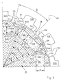
- FIG. 1 shows an electronically commutated, three-phase internal rotor motor 20 with a housing 22, which has a cylindrical housing part 24, an A-end shield 26 and a mounting flange 29.
- the stator 28 has an inner recess 34 in which an eight-pole Inner rotor 36 with a laminated core 37 made of electrical steel (DIN 46400, sheet 1), preferably sheet metal V400, and with a total of eight permanent magnets 38A to 38H (see Fig. 2 and 3) is arranged on a shaft 40, the drive end with 42 and the inner end of the shaft are denoted by 44.
- An air gap 39 separates the stator 28 from the rotor 36.
- Such a motor 20 can in various ways are designated, e.g. as permanently excited synchronous internal rotor machine or as an electronically commutated sine motor, or as a three-phase motor with impressed sinusoidal currents.
- A-end shield 26 In the A-end shield 26 is a seal 46 for the shaft 40 in the usual way intended. Furthermore, there is a recess 48 in which a Guide member 50 is attached to the outer ring 55 of a rolling bearing 54. Of the Inner ring 60 of the rolling bearing 54 is pressed onto the shaft 40.
- a B-end shield 66th attached in the open end of the cylindrical housing part 24 in the open end of the cylindrical housing part 24.
- This has a recess 68 provided with an annular shoulder 67 for the outer ring 70 of a rolling bearing 72, the inner ring 74 on the Shaft end 44 is attached.
- the shaft 40 has a collar 78, with the it rests against the left side of the inner ring 74.
- a molding 80 made of brass by the countersunk head 81 of a Countersunk screw 82 is pressed in the direction of the shaft 40 and about is annular.
- the screw 82 is in an internal thread 84 of the Shaft end 44 screwed and thereby presses the fitting 80 in Direction to the inner ring 74.
- control magnet 110 attached, e.g. by gluing.
- the Control magnet 110 is on its in Fig. 1 right side with a Provided magnetization pattern and is used to control (not shown) magnetoresistive resistors connected to a housing cover 112 are arranged on the B side of the motor 20 and for detecting the Rotary position of the rotor 36 serve to shape and commutation of the currents in Stator 28 to control exactly.
- Fig. 2 shows in enlargement a section, taken along the line II-II of Fig. 1.
- the magnets 38A to 38H are radially polarized.
- the magnet 38A has a south pole S on the outside, a north pole N on the inside.
- the next clockwise magnet 38B has a north pole N on the outside and a south pole S on the inside, etc., as shown in the drawing.
- the stator lamination stack 27 has an armature 120 on the outside from which twelve teeth 122A-122L project radially inwardly, which are provided with widened tooth tips 124 in the manner shown, between which grooves 126 are located.
- the teeth 122 are wound with concentrated windings. This is shown Example of the phase U. This phase begins with a concentrated Winding 128G on the tooth 122G, continues in a concentrated Winding 128D on the tooth 122D, further in a winding 128A on the Tooth 122A, and a winding 128J on tooth 122J. From there it goes Line U back to neutral point 0, if a winding in star connection is used. Naturally, a delta connection is possible.
- the partial windings 128G, 128D, 128A and 128J may also be connected in parallel For example, if the motor 20 is from a lower DC power source Voltage is operated, since one then winding strands with lower Inductance and low ohmic resistance.
- winding strands V and W are indicated in Fig. 2 only because of the The expert is clear that these have the same topology, but by 22.5 ° mech. (Strand V) or 45 ° mech. (Strand W) counterclockwise are offset.
- FIG. 3 shows an enlarged detail of FIG. 2.
- the shaft 40 is not shown there, since it consists of ferromagnetic material and forms part of the magnetic circuit in the rotor 36.
- the rotor 36 has in its center a magnetic yoke 130, which in the usual way as a laminated core of stamped sheets is constructed.
- This Laminated core is preferably constructed in the same manner as that in the WO 03/081748 A1, FIGS. 2 to 8, is shown and described in detail. On the content of this WO publication is expressly referred to for the sake of brevity taken.
- the pole pieces 136 each have on their the return 130 facing Side an interface 138A, 138B, 138C, hereinafter also referred to as magnetic pole piece boundary is denoted and with a distance D and parallel one Interface 140A, 140B, 140C opposite.
- an interface 138A, 138B, 138C hereinafter also referred to as magnetic pole piece boundary is denoted and with a distance D and parallel one Interface 140A, 140B, 140C opposite.
- a magnet 38 has an angular extent ⁇ M at its magnet pole shoe interface 138, and this angular extent corresponds to that of the pole piece 136 abutting against it. If one starts from this magnetic pole piece boundary 138 in the radial direction to the outside, Thus, the width ⁇ of the pole piece 136 decreases along an approximately continuous transition zone 139 and reaches at a point 142 its smallest width ⁇ C , which is smaller than ⁇ M , as shown in FIG.
- the pole piece 136 goes laterally into the periphery extending holding parts 134a, 134b over, the magnetically saturated during operation are, in the context of the present invention mainly a have mechanical bearing function.
- Fig. 3 particularly well recognizes the pole pieces 136 in conjunction with the holding parts 134 about the form of a doctor's hat used in the US, and this provides one preferred form of these pole pieces.
- the radially outer side 144 of a pole piece is 136 formed so that in the air gap 39 is an approximately sinusoidal Flow distribution arises, i. the diameter decreases, starting from the middle a rotor pole, in the manner shown from both sides.
- a cavity 146 a, 146 b On both sides of a permanent magnet 38, based on the circumferential direction, So is in each case a cavity 146 a, 146 b, whose cross-sectional shape is similar to a right-angled triangle, where the longest side is something dented is because there is a radially outer corner of the permanent magnet 38 something in this cavity 146 protrudes.
- a permanent magnet 38 at its inner interface 140 an inner magnetic width ⁇ Mi of about 41 ° mech., So of about 91% of a pole width ⁇ p , ie the magnet 38 extends virtually to the holding part 132, and the volume of the magnets 38 is thus large.
- Fig. 4 shows the distribution of the flux lines.
- the constrictions 142 cause on the one hand a Concentration of the magnetic flux on the Polmitte, and act on the other hand as magnetic resistances, which also in the area of the pole gaps the rotor poles 136 allow a small magnetic flux, as he for a sinusoidal flux distribution is desired.
- By appropriate Dimensioning of the cavities 146 can be this lateral flow "titrate”.
- the angle ⁇ C (Fig. 3) has a maximum size of the angle of a slot pitch ⁇ s, but is preferably smaller than this.
- m is between 0.8 and 0.98
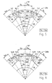
- FIGS. 5 and 6 show an illustration similar to FIG. 3.
- the stator teeth 122A to 122D are not shown in FIGS. 5 and 6 and are consistent with FIG.
- Fig. 5 shows a sector of a rotor blade 236, in which the magnet 38, 38A and 38B are indicated.
- This rotor plate 236 has symmetrical poles 136, 136A, 136B because the constrictions 142 are symmetrical about a line of symmetry 137, as shown in FIGS. 2-4.
- FIG. 6 shows a sector of a first variant of a rotor plate 236a, in which the recesses 138A, 138B for the rotor magnets 38, 38A, 38B correspond to the corresponding recesses of FIG. 5, but the constrictions 42L on the left side of a rotor pole (eg 136A) are shorter in Fig. 6 than the constrictions 142R on the right side of this pole.
Landscapes
- Engineering & Computer Science (AREA)
- Power Engineering (AREA)
- Permanent Magnet Type Synchronous Machine (AREA)
- Iron Core Of Rotating Electric Machines (AREA)
- Dc Machiner (AREA)
- Permanent Field Magnets Of Synchronous Machinery (AREA)
Priority Applications (3)
| Application Number | Priority Date | Filing Date | Title |
|---|---|---|---|
| DE202004016534U DE202004016534U1 (de) | 2003-11-05 | 2004-10-25 | Elektromotor |
| US10/981,170 US7230359B2 (en) | 2002-03-22 | 2004-11-03 | Electric motor with poles shaped to minimize cogging torque |
| JP2004322156A JP4781660B2 (ja) | 2003-11-05 | 2004-11-05 | 電気モータ |
Applications Claiming Priority (2)
| Application Number | Priority Date | Filing Date | Title |
|---|---|---|---|
| DE20317021 | 2003-11-05 | ||
| DE20317021U | 2003-11-05 |
Publications (3)
| Publication Number | Publication Date |
|---|---|
| EP1530281A2 true EP1530281A2 (fr) | 2005-05-11 |
| EP1530281A3 EP1530281A3 (fr) | 2006-03-15 |
| EP1530281B1 EP1530281B1 (fr) | 2011-11-30 |
Family
ID=34428918
Family Applications (1)
| Application Number | Title | Priority Date | Filing Date |
|---|---|---|---|
| EP04020696A Expired - Lifetime EP1530281B1 (fr) | 2002-03-22 | 2004-09-01 | Moteur électrique |
Country Status (3)
| Country | Link |
|---|---|
| EP (1) | EP1530281B1 (fr) |
| AT (1) | ATE535987T1 (fr) |
| ES (1) | ES2378310T3 (fr) |
Cited By (1)
| Publication number | Priority date | Publication date | Assignee | Title |
|---|---|---|---|---|
| DE202015105245U1 (de) | 2015-10-05 | 2017-01-09 | Ebm-Papst St. Georgen Gmbh & Co. Kg | Elektromotor |
Family Cites Families (6)
| Publication number | Priority date | Publication date | Assignee | Title |
|---|---|---|---|---|
| US6008559A (en) * | 1997-07-22 | 1999-12-28 | Matsushita Electric Industrial Co., Ltd. | Motor using a rotor including an interior permanent magnet |
| DE19933009A1 (de) * | 1998-07-24 | 2000-02-10 | Matsushita Electric Industrial Co Ltd | Motor mit interne Permanentmagneten enthaltendem Rotor und einen solchen Motor verwendende Antriebseinheit |
| US6917133B2 (en) * | 2000-08-29 | 2005-07-12 | Hitachi, Ltd. | Air conditioner having permanent magnet rotating electric machine |
| JP2002354727A (ja) * | 2001-05-21 | 2002-12-06 | Hitachi Ltd | 永久磁石を埋設した回転子および回転電機 |
| JP2003153508A (ja) * | 2001-08-29 | 2003-05-23 | Matsushita Electric Ind Co Ltd | 電動機 |
| ATE311030T1 (de) * | 2002-03-22 | 2005-12-15 | Ebm Papst St Georgen Gmbh & Co | Innenläufermotor |
-
2004
- 2004-09-01 EP EP04020696A patent/EP1530281B1/fr not_active Expired - Lifetime
- 2004-09-01 ES ES04020696T patent/ES2378310T3/es not_active Expired - Lifetime
- 2004-09-01 AT AT04020696T patent/ATE535987T1/de active
Non-Patent Citations (1)
| Title |
|---|
| None |
Cited By (2)
| Publication number | Priority date | Publication date | Assignee | Title |
|---|---|---|---|---|
| DE202015105245U1 (de) | 2015-10-05 | 2017-01-09 | Ebm-Papst St. Georgen Gmbh & Co. Kg | Elektromotor |
| DE102015119264A1 (de) | 2015-10-05 | 2017-04-06 | Ebm-Papst St. Georgen Gmbh & Co. Kg | Elektromotor |
Also Published As
| Publication number | Publication date |
|---|---|
| ATE535987T1 (de) | 2011-12-15 |
| EP1530281A3 (fr) | 2006-03-15 |
| ES2378310T3 (es) | 2012-04-11 |
| EP1530281B1 (fr) | 2011-11-30 |
Similar Documents
| Publication | Publication Date | Title |
|---|---|---|
| EP1456931B1 (fr) | Moteur a rotor interne | |
| DE60212406T2 (de) | Läufer mit eingebetteten Dauermagneten | |
| DE102004017157B4 (de) | Verfahren zur Herstellung einer Rotoranordnung und Rotoranordnung für eine elektrische Maschine | |
| EP0286905B1 (fr) | Moteur à courant continu à commutation électronique | |
| DE69724883T2 (de) | Reluktanzmotor mit Magnetpole, die aus in der Umfangsrichtung angeordneten Blechpakete bestehen | |
| DE102004011477A1 (de) | Mehrphasiger Elektromotor | |
| EP2393186A2 (fr) | Moteur électrique | |
| EP3913771A1 (fr) | Moteur électrique | |
| DE202004016534U1 (de) | Elektromotor | |
| DE102005045348A1 (de) | Zahnmodul für ein permanentmagneterregtes Primärteil einer elektrischen Maschine | |
| DE102010047551A1 (de) | Motor | |
| DE68916689T2 (de) | Elektrischer Motor. | |
| DE102005022548A1 (de) | Elektrische Maschine mit einem Wicklungssystem mit Spulengruppen | |
| DE8306650U1 (de) | Bürstenloser Gleichstrommotor | |
| DE102014115563A1 (de) | Rotor und Motor | |
| EP2704294A1 (fr) | Rotor d'une machine synchrone à excitation permanente | |
| DE102007034929A1 (de) | Transversalflussmaschine | |
| EP0358805B1 (fr) | Moteur synchrone monophasé autodémarrant | |
| DE69206911T2 (de) | Mehrphasiger, elektromagnetischer Wandler mit Dauermagnet, insbesondere Antriebsmotor | |
| DE112019001628T5 (de) | Motor | |
| DE102005004380B4 (de) | Linearmotor mit Kraftwelligkeitsausgleich | |
| DE112021005414T5 (de) | Rotor und rotierende elektrische maschine | |
| EP1530281B1 (fr) | Moteur électrique | |
| DE102013202006A1 (de) | Läuferanordnung für eine permanentmagneterregte elektrische Maschine | |
| DE102012218995A1 (de) | Läuferanordnung für eine permanentmagneterregte elektrische Maschine |
Legal Events
| Date | Code | Title | Description |
|---|---|---|---|
| PUAI | Public reference made under article 153(3) epc to a published international application that has entered the european phase |
Free format text: ORIGINAL CODE: 0009012 |
|
| AK | Designated contracting states |
Kind code of ref document: A2 Designated state(s): AT BE BG CH CY CZ DE DK EE ES FI FR GB GR HU IE IT LI LU MC NL PL PT RO SE SI SK TR |
|
| AX | Request for extension of the european patent |
Extension state: AL HR LT LV MK |
|
| PUAL | Search report despatched |
Free format text: ORIGINAL CODE: 0009013 |
|
| AK | Designated contracting states |
Kind code of ref document: A3 Designated state(s): AT BE BG CH CY CZ DE DK EE ES FI FR GB GR HU IE IT LI LU MC NL PL PT RO SE SI SK TR |
|
| AX | Request for extension of the european patent |
Extension state: AL HR LT LV MK |
|
| 17P | Request for examination filed |
Effective date: 20060223 |
|
| AKX | Designation fees paid |
Designated state(s): AT BE BG CH CY CZ DE DK EE ES FI FR GB GR HU IE IT LI LU MC NL PL PT RO SE SI SK TR |
|
| 17Q | First examination report despatched |
Effective date: 20070308 |
|
| GRAP | Despatch of communication of intention to grant a patent |
Free format text: ORIGINAL CODE: EPIDOSNIGR1 |
|
| GRAC | Information related to communication of intention to grant a patent modified |
Free format text: ORIGINAL CODE: EPIDOSCIGR1 |
|
| GRAC | Information related to communication of intention to grant a patent modified |
Free format text: ORIGINAL CODE: EPIDOSCIGR1 |
|
| GRAS | Grant fee paid |
Free format text: ORIGINAL CODE: EPIDOSNIGR3 |
|
| GRAA | (expected) grant |
Free format text: ORIGINAL CODE: 0009210 |
|
| AK | Designated contracting states |
Kind code of ref document: B1 Designated state(s): AT BE BG CH CY CZ DE DK EE ES FI FR GB GR HU IE IT LI LU MC NL PL PT RO SE SI SK TR |
|
| REG | Reference to a national code |
Ref country code: GB Ref legal event code: FG4D Free format text: NOT ENGLISH Ref country code: CH Ref legal event code: EP |
|
| REG | Reference to a national code |
Ref country code: IE Ref legal event code: FG4D Free format text: LANGUAGE OF EP DOCUMENT: GERMAN |
|
| REG | Reference to a national code |
Ref country code: DE Ref legal event code: R096 Ref document number: 502004013105 Country of ref document: DE Effective date: 20120126 |
|
| REG | Reference to a national code |
Ref country code: SE Ref legal event code: TRGR |
|
| REG | Reference to a national code |
Ref country code: NL Ref legal event code: VDEP Effective date: 20111130 |
|
| REG | Reference to a national code |
Ref country code: ES Ref legal event code: FG2A Ref document number: 2378310 Country of ref document: ES Kind code of ref document: T3 Effective date: 20120411 |
|
| PG25 | Lapsed in a contracting state [announced via postgrant information from national office to epo] |
Ref country code: NL Free format text: LAPSE BECAUSE OF FAILURE TO SUBMIT A TRANSLATION OF THE DESCRIPTION OR TO PAY THE FEE WITHIN THE PRESCRIBED TIME-LIMIT Effective date: 20111130 Ref country code: GR Free format text: LAPSE BECAUSE OF FAILURE TO SUBMIT A TRANSLATION OF THE DESCRIPTION OR TO PAY THE FEE WITHIN THE PRESCRIBED TIME-LIMIT Effective date: 20120301 Ref country code: SI Free format text: LAPSE BECAUSE OF FAILURE TO SUBMIT A TRANSLATION OF THE DESCRIPTION OR TO PAY THE FEE WITHIN THE PRESCRIBED TIME-LIMIT Effective date: 20111130 Ref country code: PT Free format text: LAPSE BECAUSE OF FAILURE TO SUBMIT A TRANSLATION OF THE DESCRIPTION OR TO PAY THE FEE WITHIN THE PRESCRIBED TIME-LIMIT Effective date: 20120330 |
|
| REG | Reference to a national code |
Ref country code: IE Ref legal event code: FD4D |
|
| PG25 | Lapsed in a contracting state [announced via postgrant information from national office to epo] |
Ref country code: CY Free format text: LAPSE BECAUSE OF FAILURE TO SUBMIT A TRANSLATION OF THE DESCRIPTION OR TO PAY THE FEE WITHIN THE PRESCRIBED TIME-LIMIT Effective date: 20111130 |
|
| PG25 | Lapsed in a contracting state [announced via postgrant information from national office to epo] |
Ref country code: CZ Free format text: LAPSE BECAUSE OF FAILURE TO SUBMIT A TRANSLATION OF THE DESCRIPTION OR TO PAY THE FEE WITHIN THE PRESCRIBED TIME-LIMIT Effective date: 20111130 Ref country code: DK Free format text: LAPSE BECAUSE OF FAILURE TO SUBMIT A TRANSLATION OF THE DESCRIPTION OR TO PAY THE FEE WITHIN THE PRESCRIBED TIME-LIMIT Effective date: 20111130 Ref country code: IE Free format text: LAPSE BECAUSE OF FAILURE TO SUBMIT A TRANSLATION OF THE DESCRIPTION OR TO PAY THE FEE WITHIN THE PRESCRIBED TIME-LIMIT Effective date: 20111130 Ref country code: BG Free format text: LAPSE BECAUSE OF FAILURE TO SUBMIT A TRANSLATION OF THE DESCRIPTION OR TO PAY THE FEE WITHIN THE PRESCRIBED TIME-LIMIT Effective date: 20120229 Ref country code: EE Free format text: LAPSE BECAUSE OF FAILURE TO SUBMIT A TRANSLATION OF THE DESCRIPTION OR TO PAY THE FEE WITHIN THE PRESCRIBED TIME-LIMIT Effective date: 20111130 Ref country code: SK Free format text: LAPSE BECAUSE OF FAILURE TO SUBMIT A TRANSLATION OF THE DESCRIPTION OR TO PAY THE FEE WITHIN THE PRESCRIBED TIME-LIMIT Effective date: 20111130 |
|
| PG25 | Lapsed in a contracting state [announced via postgrant information from national office to epo] |
Ref country code: RO Free format text: LAPSE BECAUSE OF FAILURE TO SUBMIT A TRANSLATION OF THE DESCRIPTION OR TO PAY THE FEE WITHIN THE PRESCRIBED TIME-LIMIT Effective date: 20111130 Ref country code: PL Free format text: LAPSE BECAUSE OF FAILURE TO SUBMIT A TRANSLATION OF THE DESCRIPTION OR TO PAY THE FEE WITHIN THE PRESCRIBED TIME-LIMIT Effective date: 20111130 |
|
| PLBE | No opposition filed within time limit |
Free format text: ORIGINAL CODE: 0009261 |
|
| STAA | Information on the status of an ep patent application or granted ep patent |
Free format text: STATUS: NO OPPOSITION FILED WITHIN TIME LIMIT |
|
| 26N | No opposition filed |
Effective date: 20120831 |
|
| REG | Reference to a national code |
Ref country code: DE Ref legal event code: R097 Ref document number: 502004013105 Country of ref document: DE Effective date: 20120831 |
|
| BERE | Be: lapsed |
Owner name: EBM-PAPST ST. GEORGEN G.M.B.H. & CO. KG Effective date: 20120930 |
|
| PG25 | Lapsed in a contracting state [announced via postgrant information from national office to epo] |
Ref country code: MC Free format text: LAPSE BECAUSE OF NON-PAYMENT OF DUE FEES Effective date: 20120930 |
|
| REG | Reference to a national code |
Ref country code: CH Ref legal event code: PL |
|
| PG25 | Lapsed in a contracting state [announced via postgrant information from national office to epo] |
Ref country code: FI Free format text: LAPSE BECAUSE OF FAILURE TO SUBMIT A TRANSLATION OF THE DESCRIPTION OR TO PAY THE FEE WITHIN THE PRESCRIBED TIME-LIMIT Effective date: 20111130 |
|
| PG25 | Lapsed in a contracting state [announced via postgrant information from national office to epo] |
Ref country code: LI Free format text: LAPSE BECAUSE OF NON-PAYMENT OF DUE FEES Effective date: 20120930 Ref country code: BE Free format text: LAPSE BECAUSE OF NON-PAYMENT OF DUE FEES Effective date: 20120930 Ref country code: CH Free format text: LAPSE BECAUSE OF NON-PAYMENT OF DUE FEES Effective date: 20120930 |
|
| REG | Reference to a national code |
Ref country code: AT Ref legal event code: MM01 Ref document number: 535987 Country of ref document: AT Kind code of ref document: T Effective date: 20120901 |
|
| PG25 | Lapsed in a contracting state [announced via postgrant information from national office to epo] |
Ref country code: AT Free format text: LAPSE BECAUSE OF NON-PAYMENT OF DUE FEES Effective date: 20120901 |
|
| PG25 | Lapsed in a contracting state [announced via postgrant information from national office to epo] |
Ref country code: TR Free format text: LAPSE BECAUSE OF FAILURE TO SUBMIT A TRANSLATION OF THE DESCRIPTION OR TO PAY THE FEE WITHIN THE PRESCRIBED TIME-LIMIT Effective date: 20111130 |
|
| PG25 | Lapsed in a contracting state [announced via postgrant information from national office to epo] |
Ref country code: LU Free format text: LAPSE BECAUSE OF NON-PAYMENT OF DUE FEES Effective date: 20120901 |
|
| PG25 | Lapsed in a contracting state [announced via postgrant information from national office to epo] |
Ref country code: HU Free format text: LAPSE BECAUSE OF FAILURE TO SUBMIT A TRANSLATION OF THE DESCRIPTION OR TO PAY THE FEE WITHIN THE PRESCRIBED TIME-LIMIT Effective date: 20040901 |
|
| REG | Reference to a national code |
Ref country code: FR Ref legal event code: PLFP Year of fee payment: 13 |
|
| REG | Reference to a national code |
Ref country code: FR Ref legal event code: PLFP Year of fee payment: 14 |
|
| REG | Reference to a national code |
Ref country code: FR Ref legal event code: PLFP Year of fee payment: 15 |
|
| PGFP | Annual fee paid to national office [announced via postgrant information from national office to epo] |
Ref country code: SE Payment date: 20220922 Year of fee payment: 19 Ref country code: GB Payment date: 20220927 Year of fee payment: 19 Ref country code: DE Payment date: 20220920 Year of fee payment: 19 |
|
| PGFP | Annual fee paid to national office [announced via postgrant information from national office to epo] |
Ref country code: FR Payment date: 20220921 Year of fee payment: 19 |
|
| PGFP | Annual fee paid to national office [announced via postgrant information from national office to epo] |
Ref country code: ES Payment date: 20221018 Year of fee payment: 19 Ref country code: IT Payment date: 20220930 Year of fee payment: 19 |
|
| REG | Reference to a national code |
Ref country code: DE Ref legal event code: R119 Ref document number: 502004013105 Country of ref document: DE |
|
| REG | Reference to a national code |
Ref country code: SE Ref legal event code: EUG |
|
| GBPC | Gb: european patent ceased through non-payment of renewal fee |
Effective date: 20230901 |
|
| PG25 | Lapsed in a contracting state [announced via postgrant information from national office to epo] |
Ref country code: GB Free format text: LAPSE BECAUSE OF NON-PAYMENT OF DUE FEES Effective date: 20230901 |
|
| PG25 | Lapsed in a contracting state [announced via postgrant information from national office to epo] |
Ref country code: GB Free format text: LAPSE BECAUSE OF NON-PAYMENT OF DUE FEES Effective date: 20230901 Ref country code: FR Free format text: LAPSE BECAUSE OF NON-PAYMENT OF DUE FEES Effective date: 20230930 Ref country code: DE Free format text: LAPSE BECAUSE OF NON-PAYMENT OF DUE FEES Effective date: 20240403 |
|
| PG25 | Lapsed in a contracting state [announced via postgrant information from national office to epo] |
Ref country code: SE Free format text: LAPSE BECAUSE OF NON-PAYMENT OF DUE FEES Effective date: 20230902 |
|
| REG | Reference to a national code |
Ref country code: ES Ref legal event code: FD2A Effective date: 20241025 |
|
| PG25 | Lapsed in a contracting state [announced via postgrant information from national office to epo] |
Ref country code: IT Free format text: LAPSE BECAUSE OF NON-PAYMENT OF DUE FEES Effective date: 20230901 |
|
| PG25 | Lapsed in a contracting state [announced via postgrant information from national office to epo] |
Ref country code: IT Free format text: LAPSE BECAUSE OF NON-PAYMENT OF DUE FEES Effective date: 20230901 |
|
| PG25 | Lapsed in a contracting state [announced via postgrant information from national office to epo] |
Ref country code: ES Free format text: LAPSE BECAUSE OF NON-PAYMENT OF DUE FEES Effective date: 20230902 |
|
| PG25 | Lapsed in a contracting state [announced via postgrant information from national office to epo] |
Ref country code: ES Free format text: LAPSE BECAUSE OF NON-PAYMENT OF DUE FEES Effective date: 20230902 |