EP1530281A2 - Electric motor - Google Patents
Electric motor Download PDFInfo
- Publication number
- EP1530281A2 EP1530281A2 EP04020696A EP04020696A EP1530281A2 EP 1530281 A2 EP1530281 A2 EP 1530281A2 EP 04020696 A EP04020696 A EP 04020696A EP 04020696 A EP04020696 A EP 04020696A EP 1530281 A2 EP1530281 A2 EP 1530281A2
- Authority
- EP
- European Patent Office
- Prior art keywords
- pole
- rotor
- electric motor
- motor according
- air gap
- Prior art date
- Legal status (The legal status is an assumption and is not a legal conclusion. Google has not performed a legal analysis and makes no representation as to the accuracy of the status listed.)
- Granted
Links
Images


Classifications
-
- H—ELECTRICITY
- H02—GENERATION; CONVERSION OR DISTRIBUTION OF ELECTRIC POWER
- H02K—DYNAMO-ELECTRIC MACHINES
- H02K1/00—Details of the magnetic circuit
- H02K1/06—Details of the magnetic circuit characterised by the shape, form or construction
- H02K1/22—Rotating parts of the magnetic circuit
- H02K1/27—Rotor cores with permanent magnets
- H02K1/2706—Inner rotors
- H02K1/272—Inner rotors the magnetisation axis of the magnets being perpendicular to the rotor axis
- H02K1/274—Inner rotors the magnetisation axis of the magnets being perpendicular to the rotor axis the rotor consisting of two or more circumferentially positioned magnets
- H02K1/2753—Inner rotors the magnetisation axis of the magnets being perpendicular to the rotor axis the rotor consisting of two or more circumferentially positioned magnets the rotor consisting of magnets or groups of magnets arranged with alternating polarity
- H02K1/276—Magnets embedded in the magnetic core, e.g. interior permanent magnets [IPM]
-
- H—ELECTRICITY
- H02—GENERATION; CONVERSION OR DISTRIBUTION OF ELECTRIC POWER
- H02K—DYNAMO-ELECTRIC MACHINES
- H02K21/00—Synchronous motors having permanent magnets; Synchronous generators having permanent magnets
- H02K21/12—Synchronous motors having permanent magnets; Synchronous generators having permanent magnets with stationary armatures and rotating magnets
- H02K21/14—Synchronous motors having permanent magnets; Synchronous generators having permanent magnets with stationary armatures and rotating magnets with magnets rotating within the armatures
- H02K21/16—Synchronous motors having permanent magnets; Synchronous generators having permanent magnets with stationary armatures and rotating magnets with magnets rotating within the armatures having annular armature cores with salient poles
-
- H—ELECTRICITY
- H02—GENERATION; CONVERSION OR DISTRIBUTION OF ELECTRIC POWER
- H02K—DYNAMO-ELECTRIC MACHINES
- H02K29/00—Motors or generators having non-mechanical commutating devices, e.g. discharge tubes or semiconductor devices
- H02K29/03—Motors or generators having non-mechanical commutating devices, e.g. discharge tubes or semiconductor devices with a magnetic circuit specially adapted for avoiding torque ripples or self-starting problems
Definitions
- the invention relates to an electric motor, preferably as an internal rotor motor is trained.
- Such motors are due to its low axial moment of inertia is used for drive tasks where an electric motor with its speed electrical commands follow very quickly must, e.g. for quick adjustment of parts, or for power assistance of movements.
- an engine a very to deliver uniform torque. This is usually achieved by a three-phase version of the motor, each of the phases in the significant sinusoidal current is impressed, and the engine is so is formed that in the phases ("strands") of the multiphase Stator winding sinusoidal voltages are induced.
- strands phases of the multiphase Stator winding sinusoidal voltages are induced.
- One designates such a motor as a sine motor.
- This effect is generated by a so-called reluctance torque, i. in the Rotation of the rotor relative to the stator is in the magnetic circuit of the motor magnetic energy stored in certain rotation angle ranges, and in other angular ranges, this magnetic energy is released, similar to stretching and relaxing a spring alternately.
- reluctance torque i. in the Rotation of the rotor relative to the stator is in the magnetic circuit of the motor magnetic energy stored in certain rotation angle ranges, and in other angular ranges, this magnetic energy is released, similar to stretching and relaxing a spring alternately.
- To store energy must be supplied to the rotor, i. the rotor becomes thereby braked, and vice versa, there is where stored energy is released, the rotor is driven. If you turn the rotor of such Motor by hand, one has the impression that one "feels every groove".
- FIG. 1 shows an electronically commutated, three-phase internal rotor motor 20 with a housing 22, which has a cylindrical housing part 24, an A-end shield 26 and a mounting flange 29.
- the stator 28 has an inner recess 34 in which an eight-pole Inner rotor 36 with a laminated core 37 made of electrical steel (DIN 46400, sheet 1), preferably sheet metal V400, and with a total of eight permanent magnets 38A to 38H (see Fig. 2 and 3) is arranged on a shaft 40, the drive end with 42 and the inner end of the shaft are denoted by 44.
- An air gap 39 separates the stator 28 from the rotor 36.
- Such a motor 20 can in various ways are designated, e.g. as permanently excited synchronous internal rotor machine or as an electronically commutated sine motor, or as a three-phase motor with impressed sinusoidal currents.
- A-end shield 26 In the A-end shield 26 is a seal 46 for the shaft 40 in the usual way intended. Furthermore, there is a recess 48 in which a Guide member 50 is attached to the outer ring 55 of a rolling bearing 54. Of the Inner ring 60 of the rolling bearing 54 is pressed onto the shaft 40.
- a B-end shield 66th attached in the open end of the cylindrical housing part 24 in the open end of the cylindrical housing part 24.
- This has a recess 68 provided with an annular shoulder 67 for the outer ring 70 of a rolling bearing 72, the inner ring 74 on the Shaft end 44 is attached.
- the shaft 40 has a collar 78, with the it rests against the left side of the inner ring 74.
- a molding 80 made of brass by the countersunk head 81 of a Countersunk screw 82 is pressed in the direction of the shaft 40 and about is annular.
- the screw 82 is in an internal thread 84 of the Shaft end 44 screwed and thereby presses the fitting 80 in Direction to the inner ring 74.
- control magnet 110 attached, e.g. by gluing.
- the Control magnet 110 is on its in Fig. 1 right side with a Provided magnetization pattern and is used to control (not shown) magnetoresistive resistors connected to a housing cover 112 are arranged on the B side of the motor 20 and for detecting the Rotary position of the rotor 36 serve to shape and commutation of the currents in Stator 28 to control exactly.
- Fig. 2 shows in enlargement a section, taken along the line II-II of Fig. 1.
- the magnets 38A to 38H are radially polarized.
- the magnet 38A has a south pole S on the outside, a north pole N on the inside.
- the next clockwise magnet 38B has a north pole N on the outside and a south pole S on the inside, etc., as shown in the drawing.
- the stator lamination stack 27 has an armature 120 on the outside from which twelve teeth 122A-122L project radially inwardly, which are provided with widened tooth tips 124 in the manner shown, between which grooves 126 are located.
- the teeth 122 are wound with concentrated windings. This is shown Example of the phase U. This phase begins with a concentrated Winding 128G on the tooth 122G, continues in a concentrated Winding 128D on the tooth 122D, further in a winding 128A on the Tooth 122A, and a winding 128J on tooth 122J. From there it goes Line U back to neutral point 0, if a winding in star connection is used. Naturally, a delta connection is possible.
- the partial windings 128G, 128D, 128A and 128J may also be connected in parallel For example, if the motor 20 is from a lower DC power source Voltage is operated, since one then winding strands with lower Inductance and low ohmic resistance.
- winding strands V and W are indicated in Fig. 2 only because of the The expert is clear that these have the same topology, but by 22.5 ° mech. (Strand V) or 45 ° mech. (Strand W) counterclockwise are offset.
- FIG. 3 shows an enlarged detail of FIG. 2.
- the shaft 40 is not shown there, since it consists of ferromagnetic material and forms part of the magnetic circuit in the rotor 36.
- the rotor 36 has in its center a magnetic yoke 130, which in the usual way as a laminated core of stamped sheets is constructed.
- This Laminated core is preferably constructed in the same manner as that in the WO 03/081748 A1, FIGS. 2 to 8, is shown and described in detail. On the content of this WO publication is expressly referred to for the sake of brevity taken.
- the pole pieces 136 each have on their the return 130 facing Side an interface 138A, 138B, 138C, hereinafter also referred to as magnetic pole piece boundary is denoted and with a distance D and parallel one Interface 140A, 140B, 140C opposite.
- an interface 138A, 138B, 138C hereinafter also referred to as magnetic pole piece boundary is denoted and with a distance D and parallel one Interface 140A, 140B, 140C opposite.
- a magnet 38 has an angular extent ⁇ M at its magnet pole shoe interface 138, and this angular extent corresponds to that of the pole piece 136 abutting against it. If one starts from this magnetic pole piece boundary 138 in the radial direction to the outside, Thus, the width ⁇ of the pole piece 136 decreases along an approximately continuous transition zone 139 and reaches at a point 142 its smallest width ⁇ C , which is smaller than ⁇ M , as shown in FIG.
- the pole piece 136 goes laterally into the periphery extending holding parts 134a, 134b over, the magnetically saturated during operation are, in the context of the present invention mainly a have mechanical bearing function.
- Fig. 3 particularly well recognizes the pole pieces 136 in conjunction with the holding parts 134 about the form of a doctor's hat used in the US, and this provides one preferred form of these pole pieces.
- the radially outer side 144 of a pole piece is 136 formed so that in the air gap 39 is an approximately sinusoidal Flow distribution arises, i. the diameter decreases, starting from the middle a rotor pole, in the manner shown from both sides.
- a cavity 146 a, 146 b On both sides of a permanent magnet 38, based on the circumferential direction, So is in each case a cavity 146 a, 146 b, whose cross-sectional shape is similar to a right-angled triangle, where the longest side is something dented is because there is a radially outer corner of the permanent magnet 38 something in this cavity 146 protrudes.
- a permanent magnet 38 at its inner interface 140 an inner magnetic width ⁇ Mi of about 41 ° mech., So of about 91% of a pole width ⁇ p , ie the magnet 38 extends virtually to the holding part 132, and the volume of the magnets 38 is thus large.
- Fig. 4 shows the distribution of the flux lines.
- the constrictions 142 cause on the one hand a Concentration of the magnetic flux on the Polmitte, and act on the other hand as magnetic resistances, which also in the area of the pole gaps the rotor poles 136 allow a small magnetic flux, as he for a sinusoidal flux distribution is desired.
- By appropriate Dimensioning of the cavities 146 can be this lateral flow "titrate”.
- the angle ⁇ C (Fig. 3) has a maximum size of the angle of a slot pitch ⁇ s, but is preferably smaller than this.
- m is between 0.8 and 0.98
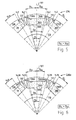
- FIGS. 5 and 6 show an illustration similar to FIG. 3.
- the stator teeth 122A to 122D are not shown in FIGS. 5 and 6 and are consistent with FIG.
- Fig. 5 shows a sector of a rotor blade 236, in which the magnet 38, 38A and 38B are indicated.
- This rotor plate 236 has symmetrical poles 136, 136A, 136B because the constrictions 142 are symmetrical about a line of symmetry 137, as shown in FIGS. 2-4.
- FIG. 6 shows a sector of a first variant of a rotor plate 236a, in which the recesses 138A, 138B for the rotor magnets 38, 38A, 38B correspond to the corresponding recesses of FIG. 5, but the constrictions 42L on the left side of a rotor pole (eg 136A) are shorter in Fig. 6 than the constrictions 142R on the right side of this pole.
Landscapes
- Engineering & Computer Science (AREA)
- Power Engineering (AREA)
- Permanent Magnet Type Synchronous Machine (AREA)
- Iron Core Of Rotating Electric Machines (AREA)
- Dc Machiner (AREA)
- Permanent Field Magnets Of Synchronous Machinery (AREA)
Abstract
Description
Die Erfindung betrifft einen Elektromotor, der bevorzugt als Innenläufermotor ausgebildet ist.The invention relates to an electric motor, preferably as an internal rotor motor is trained.
Derartige Motoren, bevorzugt mit elektronischer Kommutierung, werden wegen ihres niedrigen axialen Trägheitsmoments für Antriebsaufgaben verwendet, wo ein Elektromotor mit seiner Drehzahl elektrischen Befehlen sehr schnell folgen muss, z.B. zur schnellen Verstellung von Teilen, oder zur Servounterstützung von Bewegungen. Dabei wünscht man, dass ein solcher Motor ein sehr gleichförmiges Drehmoment abgeben soll. Dies erreicht man gewöhnlich durch eine dreiphasige Ausführung des Motors, wobei jeder der Phasen ein im wesentlichen sinusförmiger Strom eingeprägt wird, und wobei der Motor so ausgebildet ist, dass in den Phasen ("Strängen") der mehrphasigen Statorwicklung sinusförmige Spannungen induziert werden. Man bezeichnet einen solchen Motor auch als Sinusmotor.Such motors, preferably with electronic commutation, are due to its low axial moment of inertia is used for drive tasks where an electric motor with its speed electrical commands follow very quickly must, e.g. for quick adjustment of parts, or for power assistance of movements. One wishes that such an engine a very to deliver uniform torque. This is usually achieved by a three-phase version of the motor, each of the phases in the significant sinusoidal current is impressed, and the engine is so is formed that in the phases ("strands") of the multiphase Stator winding sinusoidal voltages are induced. One designates such a motor as a sine motor.
Bei solchen Motoren ergibt sich das Phänomen, dass die Grenzen zwischen den einzelnen Rotorpolen, die sogenannten Polgrenzen, die Stellen größten Luftspalts suchen. Für den Betrachter hat es deshalb den Anschein, als würden die Polgrenzen von den Nuten des Stators angezogen. Diesen Effekt bezeichnet man auf Englisch als "cogging", auf Deutsch als "Nutrucken". Das dabei entstehende Drehmoment bezeichnet man als Haltemoment oder Rastmoment (cogging torque), weil es bestrebt ist, den Rotor in bestimmten Drehstellungen festzuhalten bzw. "einzurasten".In such engines, the phenomenon arises that the boundaries between the individual rotor poles, the so-called pole boundaries, the largest points Search for air gaps. For the viewer, it therefore seems as if the pole boundaries are attracted to the slots of the stator. This effect is called in English as "cogging", in German as "Nutrucken". That here resulting torque is called a holding torque or cogging torque (cogging torque), because it strives to rotate the rotor in certain positions hold or "lock".
Dieser Effekt wird erzeugt durch ein sogenanntes Reluktanzmoment, d.h. bei der Drehung des Rotors relativ zum Stator wird im magnetischen Kreis des Motors in bestimmten Drehwinkelbereichen magnetische Energie gespeichert, und in anderen Drehwinkelbereichen wird diese magnetische Energie freigegeben, ähnlich, wie wenn man eine Feder abwechselnd spannen und entspannen würde. Zum Speichern muss dem Rotor Energie zugeführt werden, d.h. der Rotor wird dadurch gebremst, und umgekehrt wird dort, wo gespeicherte Energie freigegeben wird, der Rotor angetrieben. Dreht man den Rotor eines solchen Motors von Hand, so hat man den Eindruck, dass man "jede Nut spürt".This effect is generated by a so-called reluctance torque, i. in the Rotation of the rotor relative to the stator is in the magnetic circuit of the motor magnetic energy stored in certain rotation angle ranges, and in other angular ranges, this magnetic energy is released, similar to stretching and relaxing a spring alternately. To store energy must be supplied to the rotor, i. the rotor becomes thereby braked, and vice versa, there is where stored energy is released, the rotor is driven. If you turn the rotor of such Motor by hand, one has the impression that one "feels every groove".
Dieses Reluktanzmoment ist bei vielen Antriebsaufgaben störend, so dass man dort gezwungen ist, eisenlose Statorwicklungen zu verwenden, bei denen kein Reluktanzmoment auftritt, doch ist die Leistung solcher Motoren mit eisenlosem Stator meist nicht ausreichend, weil ihr Luftspalt sehr groß ist. Dies führt zu einem hohen Leistungsgewicht, d.h. das Verhältnis von Motorleistung zu Motorvolumen, bzw. von Motorleistung zu Motorgewicht ist bei ihnen ungünstig.This reluctance torque is disturbing in many drive tasks, so that one there is forced to use ironless stator windings, where no Reluctance torque occurs, but the performance of such engines with ironless Stator usually not enough, because their air gap is very large. this leads to a high power-to-weight ratio, i. the ratio of engine power to Engine volume, or from engine power to engine weight is unfavorable in them.
Man hat versucht, diesem Problem dadurch beizukommen, dass man den Polschuhen des Rotors eine bestimmte Form gibt, doch führt das zu einer Bauweise, bei der das Leistungsgewicht nicht günstig ist.One has tried to solve this problem by using the Pole shoes of the rotor gives a certain shape, but this leads to a Construction, in which the power-to-weight ratio is not favorable.
Es ist deshalb eine Aufgabe der Erfindung, einen neuen Elektromotor bereit zu stellen.It is therefore an object of the invention to provide a new electric motor put.
Nach der Erfindung wird das erreicht durch den Gegenstand des Anspruchs 1.
Man erhält so einen mehrsträngigen Elektromotor, bei dem man im Rotor
Magnete verwenden kann, deren Winkelerstreckung nicht viel kleiner ist als eine
Polteilung des Rotors, und bei dem man trotzdem eine induzierte Spannung mit
guter Sinusform und ein noch akzeptables Haltemoment erhält. Dies ermöglicht
es, das Leistungsgewicht solcher Motoren zu verbessern, d.h. für die gleiche
Leistung benötigt man einen kleineren und damit leichteren Motor als bisher.According to the invention, this is achieved by the subject matter of
Weitere Einzelheiten und vorteilhafte Weiterbildungen der Erfindung ergeben sich aus den im folgenden beschriebenen und in der Zeichnung dargestellten, in keiner Weise als Einschränkung der Erfindung zu verstehenden Ausführungsbeispielen, und aus den übrigen Unteransprüchen. Es zeigt:
- Fig. 1
- einen Längsschnitt durch eine bevorzugte Ausführungsform eines Motors nach der Erfindung,
- Fig. 2
- einen Schnitt, gesehen längs der Linie II-II der Fig. 1, in einem gegenüber Fig. 1 vergrößertem Maßstab,
- Fig. 3
- eine Ausschnittsvergrößerung aus Fig. 2 in einem nochmals vergrößerten Maßstab,
- Fig. 4
- eine Darstellung analog Fig. 3, bei welcher der Verlauf der magnetischen Flusslinien für eine bestimmte Rotorstellung dargestellt ist, um die Erzeugung einer sinusförmigen induzierten Spannung zu erläutern,
- Fig. 5
- eine Darstellung analog Fig. 3, nämlich die Darstellung eines Ausschnitts aus einem symmetrischen Rotorblech, und
- Fig. 6
- eine Darstellung analog Fig. 3 und 5, nämlich eine Darstellung eines Rotorblechs (Ausschnitt), bei dem die Pole leicht asymmetrisch ausgebildet sind.
- Fig. 1
- a longitudinal section through a preferred embodiment of a motor according to the invention,
- Fig. 2
- 3 is a section taken along the line II-II of FIG. 1, in a comparison with FIG. 1 enlarged scale,
- Fig. 3
- 2 shows a detail enlargement from FIG. 2 on a further enlarged scale,
- Fig. 4
- 3 shows an illustration analogous to FIG. 3, in which the course of the magnetic flux lines for a specific rotor position is illustrated, in order to explain the generation of a sinusoidal induced voltage,
- Fig. 5
- a representation analogous to FIG. 3, namely the representation of a section of a symmetrical rotor plate, and
- Fig. 6
- a representation analogous to FIGS. 3 and 5, namely a representation of a rotor plate (detail), in which the poles are slightly asymmetrical.
Fig. 1 zeigt einen elektronisch kommutierten, dreiphasigen Innenläufermotor 20
mit einem Gehäuse 22, das ein zylindrisches Gehäuseteil 24, ein A-Lagerschild
26 und einen Befestigungsflansch 29 aufweist. 1 shows an electronically commutated, three-phase
In dem zylindrischen Gehäuseteil 24 ist ein Blechpaket 27 (Fig. 2) eines
Außenstators 28 angeordnet, dessen Wickelköpfe bei 30 und 32 angedeutet
sind. Der Stator 28 hat eine Innenausnehmung 34, in der ein achtpoliger
Innenrotor 36 mit einem Blechpaket 37 aus Elektroblech (DIN 46400, Blatt 1),
bevorzugt Blech V400, und mit insgesamt acht Permanentmagneten 38A bis
38H (vgl. Fig. 2 und 3) auf einer Welle 40 angeordnet ist, deren Antriebsende mit
42 und deren inneres Wellenende mit 44 bezeichnet sind. Ein Luftspalt 39 trennt
den Stator 28 vom Rotor 36. Ein solcher Motor 20 kann in verschiedener Weise
bezeichnet werden, z.B. als permanent erregte Synchron-Innenläufermaschine
oder als elektronisch kommutierter Sinusmotor, oder als dreiphasiger Motor mit
eingeprägten sinusförmigen Strömen.In the
Im A-Lagerschild 26 ist in üblicher Weise eine Dichtung 46 für die Welle 40
vorgesehen. Ferner befindet sich dort eine Ausnehmung 48, in der ein
Führungsglied 50 für den Außenring 55 eines Wälzlagers 54 befestigt ist. Der
Innenring 60 des Wälzlagers 54 ist auf die Welle 40 aufgepresst. In the
Im offenen Ende des zylindrischen Gehäuseteils 24 ist ein B-Lagerschild 66
befestigt. Dieses hat eine mit einer Ringschulter 67 versehene Ausnehmung 68
für den Außenring 70 eines Wälzlagers 72, dessen Innenring 74 auf dem
Wellenende 44 befestigt ist. Hierzu hat die Welle 40 einen Ringbund 78, mit dem
sie gegen die linke Seite des Innenrings 74 anliegt. Gegen seine rechte Seite liegt
ein Formstück 80 aus Messing an, das durch den Senkkopf 81 einer
Senkkopfschraube 82 in Richtung zur Welle 40 gepresst wird und etwa
ringförmig ausgebildet ist. Die Schraube 82 ist in ein Innengewinde 84 des
Wellenendes 44 eingeschraubt und presst dadurch das Formstück 80 in
Richtung zum Innenring 74.In the open end of the
Zum sicheren Einspannen des Außenrings 70 dient ein flaches, ringförmiges
Teil 90, das durch drei gleichmäßig verteilte Schrauben 92 an seiner Peripherie
am Lagerschild 66 befestigt ist und das mit seinem radial inneren Teil gegen
den Außenring 70 anliegt und diesen nach links gegen die Schulter 67 presst.
(Die Ausnehmung 68 ist etwas kürzer als der Außenring 70).For secure clamping of the
Nachdem das Formstück 80 mittels der Innensechskant-Schraube 82 am
Wellenende 44 befestigt worden ist, wird in einer zylindrischen Ausnehmung des
Formstücks 80 ein Steuermagnet 110 befestigt, z.B. durch Kleben. Der
Steuermagnet 110 ist auf seiner in Fig. 1 rechten Seite mit einem
Magnetisierungsmuster versehen und dient zur Steuerung von (nicht
dargestellten) magnetoresistiven Widerständen, die an einem Gehäusedeckel
112 auf der B-Seite des Motors 20 angeordnet sind und zur Erfassung der
Drehstellung des Rotors 36 dienen, um Form und Kommutierung der Ströme im
Stator 28 exakt zu steuern.After the
Fig. 2 zeigt in Vergrößerung einen Schnitt, gesehen längs der Linie II-II der Fig. 1.
Wie man in Fig. 2 erkennt, sind die Magnete 38A bis 38H radial polarisiert. Der
Magnet 38A hat außen einen Südpol S, innen einen Nordpol N. Der im
Uhrzeigersinn nächste Magnet 38B hat außen einen Nordpol N und innen einen
Südpol S, etc., wie aus der Zeichnung ersichtlich. Fig. 2 shows in enlargement a section, taken along the line II-II of Fig. 1. As can be seen in Fig. 2, the
Das Statorblechpaket 27 hat außen einen Rückschluss (armature) 120, von dem
zwölf Zähne 122A bis 122L radial nach innen ragen, die in der dargestellten
Weise mit verbreiterten Zahnköpfen 124 versehen sind, zwischen denen sich
Nuten 126 befinden. Die Nutteilung zwischen zwei benachbarten Statornuten
126 ist mit ts bezeichnet und beträgt hier
Die Zähne 122 sind mit konzentrierten Wicklungen bewickelt. Dargestellt ist das
beispielhaft für die Phase U. Diese Phase beginnt mit einer konzentrierten
Wicklung 128G auf dem Zahn 122G, setzt sich fort in einer konzentrierten
Wicklung 128D auf dem Zahn 122D, ferner in einer Wicklung 128A auf dem
Zahn 122A, und einer Wicklung 128J auf dem Zahn 122J. Von dort geht der
Strang U zurück zum Sternpunkt 0, falls eine Wicklung in Sternschaltung
verwendet wird. Naturgemäß ist auch eine Dreieckschaltung möglich.The
Die Teilwicklungen 128G, 128D, 128A und 128J können auch parallel geschaltet
sein, z.B., falls der Motor 20 aus einer Gleichstromquelle mit niedriger
Spannung betrieben wird, da man dann Wicklungsstränge mit niedriger
Induktivität und niedrigem ohmschem Widerstand erhält.The
Die Wicklungsstränge V und W sind in Fig. 2 nur angedeutet, da für den Fachmann klar ist, dass diese die gleiche Topologie haben, aber um 22,5° mech. (Strang V) bzw. 45° mech. (Strang W) entgegen dem Uhrzeigersinn versetzt sind.The winding strands V and W are indicated in Fig. 2 only because of the The expert is clear that these have the same topology, but by 22.5 ° mech. (Strand V) or 45 ° mech. (Strand W) counterclockwise are offset.
Bei der vorliegenden Erfindung wird angestrebt, dass in den einzelnen Strängen
U, V, W sinusförmige Spannungen induziert werden, wenn sich der Rotor 36
dreht. Man spricht deshalb auch von einem Sinusmotor, wobei in die Stränge U,
V und W sinusförmige Ströme eingeprägt werden.In the present invention, it is desirable that in the individual strands
U, V, W sinusoidal voltages are induced when the
Der Aufbau des Rotors 36 wird anhand der Fig. 3 erläutert, die einen
vergrößerten Ausschnitt aus Fig. 2 zeigt. Die Welle 40 ist dort nicht dargestellt,
da sie aus ferromagnetischem Werkstoff besteht und einen Teil des
magnetischen Kreises im Rotor 36 bildet.The structure of the
Der Rotor 36 hat in seiner Mitte einen magnetischen Rückschluss 130, der in der
üblichen Weise als Blechpaket aus gestanzten Blechen aufgebaut ist. Dieses
Blechpaket wird bevorzugt in der gleichen Weise aufgebaut, wie das in der
WO 03/081748 A1, Fig. 2 bis 8, ausführlich dargestellt und beschrieben ist. Auf
den Inhalt dieser WO-Veröffentlichung wird der Kürze halber ausdrücklich Bezug
genommen.The
Mit dem Rückschluss 130 sind über gestanzte, radial verlaufende schmale
Halteteile 132 und mit diesen verbundene, in Umfangsrichtung verlaufende
Halteteile 134a, 134b Polstücke 136A, 136B, 136C etc. verbunden. Die
Symmetrieachse des Polstücks 136B ist mit 137 bezeichnet.With the
Die Polstücke 136 haben jeweils auf ihrer dem Rückschluss 130 zugewandten
Seite eine Grenzfläche 138A, 138B, 138C, die im Folgenden auch als Magnet-Polschuh-Grenze
bezeichnet wird und der mit einem Abstand D und parallel eine
Grenzfläche 140A, 140B, 140C gegenüber liegt. Statt eines einzigen Magneten
38 könnte man diesen auch in mehrere Teile aufteilen, wie das dem Fachmann
bekannt ist.The
Zwischen diesen Grenzflächen 138, 140 sind die bereits beschriebenen
Permanentmagnete 38A, 38B, 38C eingefügt, die jeweils einen
rechteckförmigen Querschnitt haben und deren Magnetisierung insbesondere
aus Fig. 4 klar hervorgeht.Between these interfaces 138, 140 are those already described
Wie Fig. 3 zeigt, hat ein Magnet 38 an seiner Magnet-Polschuh-Grenzfläche 138
eine Winkelerstreckung βM, und diese Winkelerstreckung entspricht derjenigen
des an ihn anliegenden Polschuhs 136. Geht man von dieser Magnet-Polschuh-Grenze
138 in radialer Richtung nach außen, so nimmt die Breite β des
Polschuhs 136 längs einer etwa kontinuierlichen Übergangszone 139 ab und
erreicht an einer Stelle 142 ihre kleinste Breite βC, die kleiner ist als βM, wie aus
Fig. 3 hervorgeht.As shown in FIG. 3, a
Radial außerhalb der Stelle 142 geht der Polschuh 136 seitlich in die peripher
verlaufenden Halteteile 134a, 134b über, die im Betrieb magnetisch gesättigt
sind, also im Rahmen der vorliegenden Erfindung hauptsächlich eine
mechanisch tragende Funktion haben. Wie man aus Fig. 3 besonders gut
erkennt, haben die Polschuhe 136 in Verbindung mit den Halteteilen 134 etwa
die Form eines in den USA gebräuchlichen Doktorhuts, und dies stellt eine
bevorzugte Form dieser Polschuhe dar.Radially out of
Wie man in Fig. 3 ferner erkennt, ist die radial äußere Seite 144 eines Polschuhs
136 so ausgebildet, dass im Luftspalt 39 eine etwa sinusförmige
Flussverteilung entsteht, d.h. der Durchmesser nimmt, ausgehend von der Mitte
eines Rotorpols, in der dargestellten Weise nach beiden Seiten hin ab.As can also be seen in FIG. 3, the radially
Auf beiden Seiten eines Dauermagneten 38, bezogen auf die Umfangsrichtung,
befindet sich also jeweils ein Hohlraum 146a, 146b, dessen Querschnittsform
etwa einem rechtwinkligen Dreieck gleicht, bei dem die längste Seite etwas
eingedellt ist, weil dort ein radial äußeres Eck des Dauermagneten 38 etwas in
diesen Hohlraum 146 hineinragt.On both sides of a
In Fig. 3 ist auch die Polteilung τp des Rotorpols 136B eingetragen. Da der Rotor
36 acht Pole 136 hat, entspricht eine Polteilung
Wie ebenfalls in Fig. 3 eingetragen, hat ein Dauermagnet 38 an seiner inneren
Grenzfläche 140 eine innere Magnetbreite βMi von etwa 41 ° mech., also von ca.
91 % einer Polbreite τp, d.h. der Magnet 38 erstreckt sich praktisch bis zum
Halteteil 132, und das Volumen der Magnete 38 ist folglich groß.As also indicated in Fig. 3, has a
Im Normalfall wäre eine solche Rotor-Topologie sehr ungünstig und würde zu
einer eher rechteckförmigen Flussverteilung im Luftspalt 39 und einem hohen
Rastmoment führen. Durch die Einschnürung 142 der Polschuhe 136 mit dem
Winkel βC, der kleiner ist als βM, erhält man jedoch eine Flussverteilung, die sehr
gut an die Sinusform angenähert ist.In the normal case, such a rotor topology would be very unfavorable and would lead to a rather rectangular flow distribution in the
Hierzu wird hingewiesen auf Fig. 4, welche die Verteilung der Flusslinien zeigt. Reference is made to Fig. 4 , which shows the distribution of the flux lines.
Wie man z.B. beim Magnet 38B sieht, geht an seinen beiden Seiten, bezogen
auf die Umfangsrichtung, ein Teil des Flusses durch die Hohlräume 146 (Fig. 3)
im Bereich der Verengungen 142, wobei diese Hohlräume wie ein zusätzlicher
Luftspalt wirken, also wie ein zusätzlicher magnetischer Widerstand, und da
sich ein Hohlraum 146 jeweils in Richtung weg von der Engstelle 142 in
Umfangsrichtung erweitert, nimmt auch der magnetische Widerstand in
Richtung weg von dieser Stelle 142 (Fig. 3) in Umfangsrichtung zu. Man erhält
dadurch die aus Fig. 4 ersichtliche, im wesentlichen sinusförmige
Flussverteilung, d.h. die Verengungen 142 bewirken einerseits eine
Konzentration des magnetischen Flusses auf die Polmitte, und wirken
andererseits als magnetische Widerstände, die auch im Bereich der Pollücken
der Rotorpole 136 einen kleinen magnetischen Fluss ermöglichen, wie er für eine
sinusförmige Flussverteilung erwünscht ist. Durch entsprechende
Dimensionierung der Hohlräume 146 kann man diesen seitlichen Fluss
"titrieren".For example, as looks at the
Dabei hat es sich als wichtig für die Größe des Rastmoments erwiesen, dass
der Winkel βC (Fig. 3) maximal die Größe des Winkels einer Nutteilung τs hat,
bevorzugt aber kleiner ist als dieser. Beim dargestellten Ausführungsbeispiel
beträgt
und alle Winkel in mechanischen Graden gemessen werden.It has proven to be important for the size of the cogging torque that the angle β C (Fig. 3) has a maximum size of the angle of a slot pitch τs, but is preferably smaller than this. In the illustrated embodiment amounts
and all angles are measured in mechanical degrees.
Wird eine verteilte Wicklung verwendet, so lautet die Gleichung
m = 0,8...1,0 und
n =1,2, 3,...If a distributed winding is used, the equation is
m = 0.8 ... 1.0 and
n = 1,2, 3, ...
Bevorzugt liegt m zwischen 0,8 und 0.98 Preferably, m is between 0.8 and 0.98
Es hat sich gezeigt, dass auf diese Weise, insbesondere bei Verwendung von
konzentrierten Wicklungen, eine sehr gute Sinusform der induzierten Spannung
erzielt werden kann, in Verbindung mit einem akzeptablen Rastmoment. Die
erhebliche Breite βMi der Magnete 38 ermöglicht dabei eine entsprechende
Verkleinerung des Motors 20, verglichen mit bisherigen Versionen. Bei einem
ausgeführten Muster ergab sich z.B. eine Verkürzung des Motors von bisher 68
auf jetzt 50 mm bei gleicher Leistung. (In der Praxis können sich naturgemäß
differierende Werte ergeben.)It has been found that in this way, in particular when using concentrated windings, a very good sinusoidal shape of the induced voltage can be achieved, in conjunction with an acceptable cogging torque. The considerable width β Mi of the
Die Fig. 5 und 6 zeigen eine Darstellung analog Fig. 3. Die Statorzähne 122A bis
122D sind in Fig. 5 und 6 nicht dargestellt und stimmen mit Fig. 3 überein.FIGS. 5 and 6 show an illustration similar to FIG. 3. The
Fig. 5 zeigt einen Sektor eines Rotorblechs 236, bei dem die Magnet 38, 38A
und 38B angedeutet sind. Dieses Rotorblech 236 hat symmetrische Pole 136,
136A, 136B, weil die Verengungen 142 symmetrisch zu einer Symmetrielinie 137
liegen, wie das auch in den Fig. 2 bis 4 dargestellt ist. Fig. 5 shows a sector of a
Fig. 6 zeigt davon abweichend einen Sektor einer ersten Variante eines
Rotorblechs 236a, bei dem die Ausnehmungen 138A, 138B für die
Rotormagnete 38, 38A, 38B mit den entsprechenden Ausnehmungen der Fig. 5
übereinstimmen, aber die Einschnürungen 42L auf der linken Seite eines
Rotorpols (z. B. 136A) sind bei Fig. 6 kürzer als die Verengungen 142R auf der
rechten Seite dieses Pols. 6 shows a sector of a first variant of a
Dadurch bleibt zwar die Größe des Winkels βC gegenüber Fig. 5 unverändert,
aber der Winkel βCL zwischen der Symmetrielinie 137 und der linken Verengung
142L ist größer als der Winkel βCR zwischen der Symmetrielinie 137 und der
rechten Verengung 142R, so dass gilt:
Umgekehrt kann man bei einer zweiten Version mit (nicht dargestellten) Blechen
236b in gleicher Weise βCR größer machen als βCL, was nicht dargestellt ist. Dies
geschieht einfach durch Invertieren des in Fig. 6 dargestellten Blechs 236a, so
dass dessen Unterseite nach oben kommt.Conversely, in a second version with plates 236b (not shown), one can make β CR larger than β CL in the same way, which is not shown. This is done simply by inverting the
Wenn man nun ein Rotorblechpaket in der Weise herstellt, dass man z. B. zuerst
ein symmetrisches Blech 236 gemäß Fig. 5 verwendet, darauf ein
unsymmetrisches Blech 236a gemäß Fig. 6, darauf ein unsymmetrisches Blech
236b (invertiertes Blech 236a), darauf wieder ein Blech 236, dann 236a, etc., so
ergibt sich eine bessere Form der Spannung, welche in der (nicht dargestellten)
Statorwicklung induziert wird, und man erhält durch diese einfache Maßnahme
folglich ein gleichmäßigeres Drehmoment.If you now produce a rotor core in such a way that z. Eg first
a
Zu beachten ist, dass die Öffnungen 138A, 138B für die Magnete 38 bei allen
Blechen 236, 236a, 236b die gleiche Lage haben, so dass auch die
Symmetrielinien 137 bei allen Blechen übereinstimmen.It should be noted that the
Naturgemäß sind im Rahmen der vorliegenden Erfindung vielfache Abwandlungen und Modifikationen möglich.Naturally, within the scope of the present invention are multiple Modifications and modifications possible.
Claims (12)
und die Winkel βC und τS in mechanischen Graden angegeben sind.Electric motor, which has
and the angles β C and τ S are given in mechanical degrees.
und bei mindestens einem Teil dieser Bleche die Stelle geringster Erstreckung (βC) in Umfangsrichtung relativ zu einer gedachten Symmetrieachse (137) der Polschuhe versetzt ist.Electric motor according to claim 1, in which the pole shoes are formed from sheets,
and in at least a part of these sheets, the point of least extent (β C ) in the circumferential direction is offset relative to an imaginary axis of symmetry (137) of the pole pieces.
Priority Applications (3)
| Application Number | Priority Date | Filing Date | Title |
|---|---|---|---|
| DE202004016534U DE202004016534U1 (en) | 2003-11-05 | 2004-10-25 | electric motor |
| US10/981,170 US7230359B2 (en) | 2002-03-22 | 2004-11-03 | Electric motor with poles shaped to minimize cogging torque |
| JP2004322156A JP4781660B2 (en) | 2003-11-05 | 2004-11-05 | Electric motor |
Applications Claiming Priority (2)
| Application Number | Priority Date | Filing Date | Title |
|---|---|---|---|
| DE20317021 | 2003-11-05 | ||
| DE20317021U | 2003-11-05 |
Publications (3)
| Publication Number | Publication Date |
|---|---|
| EP1530281A2 true EP1530281A2 (en) | 2005-05-11 |
| EP1530281A3 EP1530281A3 (en) | 2006-03-15 |
| EP1530281B1 EP1530281B1 (en) | 2011-11-30 |
Family
ID=34428918
Family Applications (1)
| Application Number | Title | Priority Date | Filing Date |
|---|---|---|---|
| EP04020696A Expired - Lifetime EP1530281B1 (en) | 2002-03-22 | 2004-09-01 | Electric motor |
Country Status (3)
| Country | Link |
|---|---|
| EP (1) | EP1530281B1 (en) |
| AT (1) | ATE535987T1 (en) |
| ES (1) | ES2378310T3 (en) |
Cited By (1)
| Publication number | Priority date | Publication date | Assignee | Title |
|---|---|---|---|---|
| DE202015105245U1 (en) | 2015-10-05 | 2017-01-09 | Ebm-Papst St. Georgen Gmbh & Co. Kg | electric motor |
Family Cites Families (6)
| Publication number | Priority date | Publication date | Assignee | Title |
|---|---|---|---|---|
| US6008559A (en) * | 1997-07-22 | 1999-12-28 | Matsushita Electric Industrial Co., Ltd. | Motor using a rotor including an interior permanent magnet |
| DE19933009A1 (en) * | 1998-07-24 | 2000-02-10 | Matsushita Electric Industrial Co Ltd | Electric motor e.g. for automobile air conditioning unit, has rotor core provided with slits for reception of internal permanent magnets with non-magnetic section between each permanent magnet and rotor periphery |
| US6917133B2 (en) * | 2000-08-29 | 2005-07-12 | Hitachi, Ltd. | Air conditioner having permanent magnet rotating electric machine |
| JP2002354727A (en) * | 2001-05-21 | 2002-12-06 | Hitachi Ltd | Rotor and rotating electric machine with permanent magnet embedded |
| JP2003153508A (en) * | 2001-08-29 | 2003-05-23 | Matsushita Electric Ind Co Ltd | Electric motor |
| ATE311030T1 (en) * | 2002-03-22 | 2005-12-15 | Ebm Papst St Georgen Gmbh & Co | INNER ROTOR MOTOR |
-
2004
- 2004-09-01 EP EP04020696A patent/EP1530281B1/en not_active Expired - Lifetime
- 2004-09-01 ES ES04020696T patent/ES2378310T3/en not_active Expired - Lifetime
- 2004-09-01 AT AT04020696T patent/ATE535987T1/en active
Non-Patent Citations (1)
| Title |
|---|
| None |
Cited By (2)
| Publication number | Priority date | Publication date | Assignee | Title |
|---|---|---|---|---|
| DE202015105245U1 (en) | 2015-10-05 | 2017-01-09 | Ebm-Papst St. Georgen Gmbh & Co. Kg | electric motor |
| DE102015119264A1 (en) | 2015-10-05 | 2017-04-06 | Ebm-Papst St. Georgen Gmbh & Co. Kg | electric motor |
Also Published As
| Publication number | Publication date |
|---|---|
| ATE535987T1 (en) | 2011-12-15 |
| EP1530281A3 (en) | 2006-03-15 |
| ES2378310T3 (en) | 2012-04-11 |
| EP1530281B1 (en) | 2011-11-30 |
Similar Documents
| Publication | Publication Date | Title |
|---|---|---|
| EP1456931B1 (en) | Inner rotor motor | |
| DE60212406T2 (en) | Runners with embedded permanent magnets | |
| DE102004017157B4 (en) | Method for producing a rotor assembly and rotor assembly for an electrical machine | |
| EP0286905B1 (en) | Electronically commutated brushless dc motor | |
| DE69724883T2 (en) | Reluctance motor with magnetic poles, which consist of laminated cores arranged in the circumferential direction | |
| DE102004011477A1 (en) | Multiphase electric motor for various applications has permanent magnets with chamfered edges arranged to form square in rotor to make pole shoes | |
| EP2393186A2 (en) | Electric motor | |
| EP3913771A1 (en) | Electric motor | |
| DE202004016534U1 (en) | electric motor | |
| DE102005045348A1 (en) | Tooth module for a permanent magnet excited primary part of an electrical machine | |
| DE102010047551A1 (en) | engine | |
| DE68916689T2 (en) | Electric motor. | |
| DE102005022548A1 (en) | Electric machine with a winding system with coil groups | |
| DE8306650U1 (en) | Brushless DC motor | |
| DE102014115563A1 (en) | Rotor and motor | |
| EP2704294A1 (en) | Rotor of a permanently excited synchronous machine | |
| DE102007034929A1 (en) | transverse flux | |
| EP0358805B1 (en) | Self-starting single-phase synchronous motor | |
| DE69206911T2 (en) | Multi-phase, electromagnetic converter with permanent magnet, especially drive motor | |
| DE112019001628T5 (en) | ENGINE | |
| DE102005004380B4 (en) | Linear motor with force ripple compensation | |
| DE112021005414T5 (en) | ROTOR AND ROTATING ELECTRICAL MACHINE | |
| EP1530281B1 (en) | Electric motor | |
| DE102013202006A1 (en) | Rotor assembly for electric machine, has permanent magnet with first and second portions that are transverse to arrangement direction of pole shoes, while thickness of the pole shoes are different in arrangement direction | |
| DE102012218995A1 (en) | Rotor assembly for permanent magnet-energized rotary electric machine, has permanent magnets whose tangential thickness of portion near to the rear end region is smaller than portion far from the rear end region |
Legal Events
| Date | Code | Title | Description |
|---|---|---|---|
| PUAI | Public reference made under article 153(3) epc to a published international application that has entered the european phase |
Free format text: ORIGINAL CODE: 0009012 |
|
| AK | Designated contracting states |
Kind code of ref document: A2 Designated state(s): AT BE BG CH CY CZ DE DK EE ES FI FR GB GR HU IE IT LI LU MC NL PL PT RO SE SI SK TR |
|
| AX | Request for extension of the european patent |
Extension state: AL HR LT LV MK |
|
| PUAL | Search report despatched |
Free format text: ORIGINAL CODE: 0009013 |
|
| AK | Designated contracting states |
Kind code of ref document: A3 Designated state(s): AT BE BG CH CY CZ DE DK EE ES FI FR GB GR HU IE IT LI LU MC NL PL PT RO SE SI SK TR |
|
| AX | Request for extension of the european patent |
Extension state: AL HR LT LV MK |
|
| 17P | Request for examination filed |
Effective date: 20060223 |
|
| AKX | Designation fees paid |
Designated state(s): AT BE BG CH CY CZ DE DK EE ES FI FR GB GR HU IE IT LI LU MC NL PL PT RO SE SI SK TR |
|
| 17Q | First examination report despatched |
Effective date: 20070308 |
|
| GRAP | Despatch of communication of intention to grant a patent |
Free format text: ORIGINAL CODE: EPIDOSNIGR1 |
|
| GRAC | Information related to communication of intention to grant a patent modified |
Free format text: ORIGINAL CODE: EPIDOSCIGR1 |
|
| GRAC | Information related to communication of intention to grant a patent modified |
Free format text: ORIGINAL CODE: EPIDOSCIGR1 |
|
| GRAS | Grant fee paid |
Free format text: ORIGINAL CODE: EPIDOSNIGR3 |
|
| GRAA | (expected) grant |
Free format text: ORIGINAL CODE: 0009210 |
|
| AK | Designated contracting states |
Kind code of ref document: B1 Designated state(s): AT BE BG CH CY CZ DE DK EE ES FI FR GB GR HU IE IT LI LU MC NL PL PT RO SE SI SK TR |
|
| REG | Reference to a national code |
Ref country code: GB Ref legal event code: FG4D Free format text: NOT ENGLISH Ref country code: CH Ref legal event code: EP |
|
| REG | Reference to a national code |
Ref country code: IE Ref legal event code: FG4D Free format text: LANGUAGE OF EP DOCUMENT: GERMAN |
|
| REG | Reference to a national code |
Ref country code: DE Ref legal event code: R096 Ref document number: 502004013105 Country of ref document: DE Effective date: 20120126 |
|
| REG | Reference to a national code |
Ref country code: SE Ref legal event code: TRGR |
|
| REG | Reference to a national code |
Ref country code: NL Ref legal event code: VDEP Effective date: 20111130 |
|
| REG | Reference to a national code |
Ref country code: ES Ref legal event code: FG2A Ref document number: 2378310 Country of ref document: ES Kind code of ref document: T3 Effective date: 20120411 |
|
| PG25 | Lapsed in a contracting state [announced via postgrant information from national office to epo] |
Ref country code: NL Free format text: LAPSE BECAUSE OF FAILURE TO SUBMIT A TRANSLATION OF THE DESCRIPTION OR TO PAY THE FEE WITHIN THE PRESCRIBED TIME-LIMIT Effective date: 20111130 Ref country code: GR Free format text: LAPSE BECAUSE OF FAILURE TO SUBMIT A TRANSLATION OF THE DESCRIPTION OR TO PAY THE FEE WITHIN THE PRESCRIBED TIME-LIMIT Effective date: 20120301 Ref country code: SI Free format text: LAPSE BECAUSE OF FAILURE TO SUBMIT A TRANSLATION OF THE DESCRIPTION OR TO PAY THE FEE WITHIN THE PRESCRIBED TIME-LIMIT Effective date: 20111130 Ref country code: PT Free format text: LAPSE BECAUSE OF FAILURE TO SUBMIT A TRANSLATION OF THE DESCRIPTION OR TO PAY THE FEE WITHIN THE PRESCRIBED TIME-LIMIT Effective date: 20120330 |
|
| REG | Reference to a national code |
Ref country code: IE Ref legal event code: FD4D |
|
| PG25 | Lapsed in a contracting state [announced via postgrant information from national office to epo] |
Ref country code: CY Free format text: LAPSE BECAUSE OF FAILURE TO SUBMIT A TRANSLATION OF THE DESCRIPTION OR TO PAY THE FEE WITHIN THE PRESCRIBED TIME-LIMIT Effective date: 20111130 |
|
| PG25 | Lapsed in a contracting state [announced via postgrant information from national office to epo] |
Ref country code: CZ Free format text: LAPSE BECAUSE OF FAILURE TO SUBMIT A TRANSLATION OF THE DESCRIPTION OR TO PAY THE FEE WITHIN THE PRESCRIBED TIME-LIMIT Effective date: 20111130 Ref country code: DK Free format text: LAPSE BECAUSE OF FAILURE TO SUBMIT A TRANSLATION OF THE DESCRIPTION OR TO PAY THE FEE WITHIN THE PRESCRIBED TIME-LIMIT Effective date: 20111130 Ref country code: IE Free format text: LAPSE BECAUSE OF FAILURE TO SUBMIT A TRANSLATION OF THE DESCRIPTION OR TO PAY THE FEE WITHIN THE PRESCRIBED TIME-LIMIT Effective date: 20111130 Ref country code: BG Free format text: LAPSE BECAUSE OF FAILURE TO SUBMIT A TRANSLATION OF THE DESCRIPTION OR TO PAY THE FEE WITHIN THE PRESCRIBED TIME-LIMIT Effective date: 20120229 Ref country code: EE Free format text: LAPSE BECAUSE OF FAILURE TO SUBMIT A TRANSLATION OF THE DESCRIPTION OR TO PAY THE FEE WITHIN THE PRESCRIBED TIME-LIMIT Effective date: 20111130 Ref country code: SK Free format text: LAPSE BECAUSE OF FAILURE TO SUBMIT A TRANSLATION OF THE DESCRIPTION OR TO PAY THE FEE WITHIN THE PRESCRIBED TIME-LIMIT Effective date: 20111130 |
|
| PG25 | Lapsed in a contracting state [announced via postgrant information from national office to epo] |
Ref country code: RO Free format text: LAPSE BECAUSE OF FAILURE TO SUBMIT A TRANSLATION OF THE DESCRIPTION OR TO PAY THE FEE WITHIN THE PRESCRIBED TIME-LIMIT Effective date: 20111130 Ref country code: PL Free format text: LAPSE BECAUSE OF FAILURE TO SUBMIT A TRANSLATION OF THE DESCRIPTION OR TO PAY THE FEE WITHIN THE PRESCRIBED TIME-LIMIT Effective date: 20111130 |
|
| PLBE | No opposition filed within time limit |
Free format text: ORIGINAL CODE: 0009261 |
|
| STAA | Information on the status of an ep patent application or granted ep patent |
Free format text: STATUS: NO OPPOSITION FILED WITHIN TIME LIMIT |
|
| 26N | No opposition filed |
Effective date: 20120831 |
|
| REG | Reference to a national code |
Ref country code: DE Ref legal event code: R097 Ref document number: 502004013105 Country of ref document: DE Effective date: 20120831 |
|
| BERE | Be: lapsed |
Owner name: EBM-PAPST ST. GEORGEN G.M.B.H. & CO. KG Effective date: 20120930 |
|
| PG25 | Lapsed in a contracting state [announced via postgrant information from national office to epo] |
Ref country code: MC Free format text: LAPSE BECAUSE OF NON-PAYMENT OF DUE FEES Effective date: 20120930 |
|
| REG | Reference to a national code |
Ref country code: CH Ref legal event code: PL |
|
| PG25 | Lapsed in a contracting state [announced via postgrant information from national office to epo] |
Ref country code: FI Free format text: LAPSE BECAUSE OF FAILURE TO SUBMIT A TRANSLATION OF THE DESCRIPTION OR TO PAY THE FEE WITHIN THE PRESCRIBED TIME-LIMIT Effective date: 20111130 |
|
| PG25 | Lapsed in a contracting state [announced via postgrant information from national office to epo] |
Ref country code: LI Free format text: LAPSE BECAUSE OF NON-PAYMENT OF DUE FEES Effective date: 20120930 Ref country code: BE Free format text: LAPSE BECAUSE OF NON-PAYMENT OF DUE FEES Effective date: 20120930 Ref country code: CH Free format text: LAPSE BECAUSE OF NON-PAYMENT OF DUE FEES Effective date: 20120930 |
|
| REG | Reference to a national code |
Ref country code: AT Ref legal event code: MM01 Ref document number: 535987 Country of ref document: AT Kind code of ref document: T Effective date: 20120901 |
|
| PG25 | Lapsed in a contracting state [announced via postgrant information from national office to epo] |
Ref country code: AT Free format text: LAPSE BECAUSE OF NON-PAYMENT OF DUE FEES Effective date: 20120901 |
|
| PG25 | Lapsed in a contracting state [announced via postgrant information from national office to epo] |
Ref country code: TR Free format text: LAPSE BECAUSE OF FAILURE TO SUBMIT A TRANSLATION OF THE DESCRIPTION OR TO PAY THE FEE WITHIN THE PRESCRIBED TIME-LIMIT Effective date: 20111130 |
|
| PG25 | Lapsed in a contracting state [announced via postgrant information from national office to epo] |
Ref country code: LU Free format text: LAPSE BECAUSE OF NON-PAYMENT OF DUE FEES Effective date: 20120901 |
|
| PG25 | Lapsed in a contracting state [announced via postgrant information from national office to epo] |
Ref country code: HU Free format text: LAPSE BECAUSE OF FAILURE TO SUBMIT A TRANSLATION OF THE DESCRIPTION OR TO PAY THE FEE WITHIN THE PRESCRIBED TIME-LIMIT Effective date: 20040901 |
|
| REG | Reference to a national code |
Ref country code: FR Ref legal event code: PLFP Year of fee payment: 13 |
|
| REG | Reference to a national code |
Ref country code: FR Ref legal event code: PLFP Year of fee payment: 14 |
|
| REG | Reference to a national code |
Ref country code: FR Ref legal event code: PLFP Year of fee payment: 15 |
|
| PGFP | Annual fee paid to national office [announced via postgrant information from national office to epo] |
Ref country code: SE Payment date: 20220922 Year of fee payment: 19 Ref country code: GB Payment date: 20220927 Year of fee payment: 19 Ref country code: DE Payment date: 20220920 Year of fee payment: 19 |
|
| PGFP | Annual fee paid to national office [announced via postgrant information from national office to epo] |
Ref country code: FR Payment date: 20220921 Year of fee payment: 19 |
|
| PGFP | Annual fee paid to national office [announced via postgrant information from national office to epo] |
Ref country code: ES Payment date: 20221018 Year of fee payment: 19 Ref country code: IT Payment date: 20220930 Year of fee payment: 19 |
|
| REG | Reference to a national code |
Ref country code: DE Ref legal event code: R119 Ref document number: 502004013105 Country of ref document: DE |
|
| REG | Reference to a national code |
Ref country code: SE Ref legal event code: EUG |
|
| GBPC | Gb: european patent ceased through non-payment of renewal fee |
Effective date: 20230901 |
|
| PG25 | Lapsed in a contracting state [announced via postgrant information from national office to epo] |
Ref country code: GB Free format text: LAPSE BECAUSE OF NON-PAYMENT OF DUE FEES Effective date: 20230901 |
|
| PG25 | Lapsed in a contracting state [announced via postgrant information from national office to epo] |
Ref country code: GB Free format text: LAPSE BECAUSE OF NON-PAYMENT OF DUE FEES Effective date: 20230901 Ref country code: FR Free format text: LAPSE BECAUSE OF NON-PAYMENT OF DUE FEES Effective date: 20230930 Ref country code: DE Free format text: LAPSE BECAUSE OF NON-PAYMENT OF DUE FEES Effective date: 20240403 |
|
| PG25 | Lapsed in a contracting state [announced via postgrant information from national office to epo] |
Ref country code: SE Free format text: LAPSE BECAUSE OF NON-PAYMENT OF DUE FEES Effective date: 20230902 |
|
| REG | Reference to a national code |
Ref country code: ES Ref legal event code: FD2A Effective date: 20241025 |
|
| PG25 | Lapsed in a contracting state [announced via postgrant information from national office to epo] |
Ref country code: IT Free format text: LAPSE BECAUSE OF NON-PAYMENT OF DUE FEES Effective date: 20230901 |
|
| PG25 | Lapsed in a contracting state [announced via postgrant information from national office to epo] |
Ref country code: IT Free format text: LAPSE BECAUSE OF NON-PAYMENT OF DUE FEES Effective date: 20230901 |
|
| PG25 | Lapsed in a contracting state [announced via postgrant information from national office to epo] |
Ref country code: ES Free format text: LAPSE BECAUSE OF NON-PAYMENT OF DUE FEES Effective date: 20230902 |
|
| PG25 | Lapsed in a contracting state [announced via postgrant information from national office to epo] |
Ref country code: ES Free format text: LAPSE BECAUSE OF NON-PAYMENT OF DUE FEES Effective date: 20230902 |