EP1530013A2 - Expansion valve having solenoid relief valve - Google Patents
Expansion valve having solenoid relief valve Download PDFInfo
- Publication number
- EP1530013A2 EP1530013A2 EP04026014A EP04026014A EP1530013A2 EP 1530013 A2 EP1530013 A2 EP 1530013A2 EP 04026014 A EP04026014 A EP 04026014A EP 04026014 A EP04026014 A EP 04026014A EP 1530013 A2 EP1530013 A2 EP 1530013A2
- Authority
- EP
- European Patent Office
- Prior art keywords
- valve
- relief valve
- refrigerant
- chamber
- passage
- Prior art date
- Legal status (The legal status is an assumption and is not a legal conclusion. Google has not performed a legal analysis and makes no representation as to the accuracy of the status listed.)
- Granted
Links
- 239000003507 refrigerant Substances 0.000 claims abstract description 70
- 238000005057 refrigeration Methods 0.000 claims description 19
- 230000006835 compression Effects 0.000 claims description 2
- 238000007906 compression Methods 0.000 claims description 2
- 238000007599 discharging Methods 0.000 abstract description 4
- 230000005611 electricity Effects 0.000 abstract description 3
- 238000004378 air conditioning Methods 0.000 abstract 1
- 230000001133 acceleration Effects 0.000 description 3
- 239000004809 Teflon Substances 0.000 description 1
- 229920006362 Teflon® Polymers 0.000 description 1
- 238000001514 detection method Methods 0.000 description 1
- 239000013013 elastic material Substances 0.000 description 1
- 239000012530 fluid Substances 0.000 description 1
- 239000007791 liquid phase Substances 0.000 description 1
Images

Classifications
-
- F—MECHANICAL ENGINEERING; LIGHTING; HEATING; WEAPONS; BLASTING
- F25—REFRIGERATION OR COOLING; COMBINED HEATING AND REFRIGERATION SYSTEMS; HEAT PUMP SYSTEMS; MANUFACTURE OR STORAGE OF ICE; LIQUEFACTION SOLIDIFICATION OF GASES
- F25B—REFRIGERATION MACHINES, PLANTS OR SYSTEMS; COMBINED HEATING AND REFRIGERATION SYSTEMS; HEAT PUMP SYSTEMS
- F25B41/00—Fluid-circulation arrangements
- F25B41/30—Expansion means; Dispositions thereof
- F25B41/31—Expansion valves
- F25B41/34—Expansion valves with the valve member being actuated by electric means, e.g. by piezoelectric actuators
- F25B41/345—Expansion valves with the valve member being actuated by electric means, e.g. by piezoelectric actuators by solenoids
-
- F—MECHANICAL ENGINEERING; LIGHTING; HEATING; WEAPONS; BLASTING
- F25—REFRIGERATION OR COOLING; COMBINED HEATING AND REFRIGERATION SYSTEMS; HEAT PUMP SYSTEMS; MANUFACTURE OR STORAGE OF ICE; LIQUEFACTION SOLIDIFICATION OF GASES
- F25B—REFRIGERATION MACHINES, PLANTS OR SYSTEMS; COMBINED HEATING AND REFRIGERATION SYSTEMS; HEAT PUMP SYSTEMS
- F25B41/00—Fluid-circulation arrangements
- F25B41/30—Expansion means; Dispositions thereof
- F25B41/31—Expansion valves
- F25B41/325—Expansion valves having two or more valve members
-
- F—MECHANICAL ENGINEERING; LIGHTING; HEATING; WEAPONS; BLASTING
- F25—REFRIGERATION OR COOLING; COMBINED HEATING AND REFRIGERATION SYSTEMS; HEAT PUMP SYSTEMS; MANUFACTURE OR STORAGE OF ICE; LIQUEFACTION SOLIDIFICATION OF GASES
- F25B—REFRIGERATION MACHINES, PLANTS OR SYSTEMS; COMBINED HEATING AND REFRIGERATION SYSTEMS; HEAT PUMP SYSTEMS
- F25B41/00—Fluid-circulation arrangements
- F25B41/30—Expansion means; Dispositions thereof
- F25B41/31—Expansion valves
- F25B41/33—Expansion valves with the valve member being actuated by the fluid pressure, e.g. by the pressure of the refrigerant
- F25B41/335—Expansion valves with the valve member being actuated by the fluid pressure, e.g. by the pressure of the refrigerant via diaphragms
-
- F—MECHANICAL ENGINEERING; LIGHTING; HEATING; WEAPONS; BLASTING
- F25—REFRIGERATION OR COOLING; COMBINED HEATING AND REFRIGERATION SYSTEMS; HEAT PUMP SYSTEMS; MANUFACTURE OR STORAGE OF ICE; LIQUEFACTION SOLIDIFICATION OF GASES
- F25B—REFRIGERATION MACHINES, PLANTS OR SYSTEMS; COMBINED HEATING AND REFRIGERATION SYSTEMS; HEAT PUMP SYSTEMS
- F25B41/00—Fluid-circulation arrangements
- F25B41/30—Expansion means; Dispositions thereof
- F25B41/31—Expansion valves
- F25B41/34—Expansion valves with the valve member being actuated by electric means, e.g. by piezoelectric actuators
-
- F—MECHANICAL ENGINEERING; LIGHTING; HEATING; WEAPONS; BLASTING
- F25—REFRIGERATION OR COOLING; COMBINED HEATING AND REFRIGERATION SYSTEMS; HEAT PUMP SYSTEMS; MANUFACTURE OR STORAGE OF ICE; LIQUEFACTION SOLIDIFICATION OF GASES
- F25B—REFRIGERATION MACHINES, PLANTS OR SYSTEMS; COMBINED HEATING AND REFRIGERATION SYSTEMS; HEAT PUMP SYSTEMS
- F25B49/00—Arrangement or mounting of control or safety devices
- F25B49/005—Arrangement or mounting of control or safety devices of safety devices
-
- F—MECHANICAL ENGINEERING; LIGHTING; HEATING; WEAPONS; BLASTING
- F25—REFRIGERATION OR COOLING; COMBINED HEATING AND REFRIGERATION SYSTEMS; HEAT PUMP SYSTEMS; MANUFACTURE OR STORAGE OF ICE; LIQUEFACTION SOLIDIFICATION OF GASES
- F25B—REFRIGERATION MACHINES, PLANTS OR SYSTEMS; COMBINED HEATING AND REFRIGERATION SYSTEMS; HEAT PUMP SYSTEMS
- F25B2341/00—Details of ejectors not being used as compression device; Details of flow restrictors or expansion valves
- F25B2341/06—Details of flow restrictors or expansion valves
- F25B2341/068—Expansion valves combined with a sensor
- F25B2341/0683—Expansion valves combined with a sensor the sensor is disposed in the suction line and influenced by the temperature or the pressure of the suction gas
-
- Y—GENERAL TAGGING OF NEW TECHNOLOGICAL DEVELOPMENTS; GENERAL TAGGING OF CROSS-SECTIONAL TECHNOLOGIES SPANNING OVER SEVERAL SECTIONS OF THE IPC; TECHNICAL SUBJECTS COVERED BY FORMER USPC CROSS-REFERENCE ART COLLECTIONS [XRACs] AND DIGESTS
- Y02—TECHNOLOGIES OR APPLICATIONS FOR MITIGATION OR ADAPTATION AGAINST CLIMATE CHANGE
- Y02B—CLIMATE CHANGE MITIGATION TECHNOLOGIES RELATED TO BUILDINGS, e.g. HOUSING, HOUSE APPLIANCES OR RELATED END-USER APPLICATIONS
- Y02B30/00—Energy efficient heating, ventilation or air conditioning [HVAC]
- Y02B30/70—Efficient control or regulation technologies, e.g. for control of refrigerant flow, motor or heating
Definitions
- the present invention relates to an expansion valve equipped for example to an air conditioner of a vehicle, for controlling the flow rate of a refrigerant sent toward an evaporator, the expansion valve having a mechanism for discharging the refrigerant to the atmosphere in case of an emergency.
- a refrigerant used in a refrigeration cycle is required to have a property applying small load on the environment.
- some types of refrigerants are harmful to the human body or are inflammable.
- Non-patent document 1 July 15-17 2003 SAE Automotive Alternate Refrigeration Systems, "R-152a Mobile A/C with Directed Relief Safety System", Mahmoud Ghodbane, Ph. D., James A. Baker, William R. Hill and Stephen O. Andersen, Ph. D.; discloses a refrigeration cycle for discharging the refrigerant to the atmosphere at times of emergency.
- FIG. 2 shows an example of a refrigeration cycle circuit according to the above-mentioned prior art.
- the prior art refrigeration cycle illustrated in FIG. 2 is formed of a compressor 1, a condenser 2, an expansion valve 3 and an evaporator 4 which are connected in the named order via a piping 7, wherein a first relief valve 5 is connected to a pipe branched out from the piping between the compressor 1 and the condenser 2, and a second relief valve 6 is connected to a pipe branched out from the piping between the expansion valve 3 and the evaporator 4.
- relief valves are disposed at two locations in the circuit, one in a high-pressure circuit connecting the compressor and the expansion valve, and one in a low-pressure circuit connecting the expansion valve, the evaporator and the compressor.
- signals are received from a refrigerant detection sensor for detecting refrigerant leak or from an acceleration sensor that operates during collision, based on which the relief valves are opened and refrigerant is discharged.
- the refrigerant in the low-pressure circuit can be discharged, and at that time, the discharge of the low-pressure refrigerant causes the pressure in the low-pressure circuit to drop, causing the valve of the expansion valve to open and the high-pressure refrigerant to flow into the low-pressure circuit.
- This causes the pressure in the low-pressure circuit to rise and the valve of the expansion valve to close, then the refrigerant in the low-pressure circuit is discharged through the relief valve, and when the pressure in the low-pressure circuit drops, the valve of the expansion valve opens again.
- This repeated phenomenon causes the refrigerant to be discharged gradually, or in other words, slowly, taking a long time to discharge the refrigerant.
- the refrigerant is discharged from both the high-pressure circuit and the low-pressure circuit, as illustrated in the refrigeration cycle of FIG. 2.
- the present invention aims at solving the above-mentioned problems of cost and assembly operations.
- the present invention provides an assembly in which one relief valve is attached to the side wall of an expansion valve to allow the refrigerant in both the high-pressure and low-pressure circuits to be discharged simultaneously via the one relief valve.
- the assembly operation of the valve is facilitated since it can be attached to conventional expansion valves.
- the expansion valve comprises, as basic components, a valve chamber into which a high-pressure refrigerant from a compressor enters; a first passage through which flows the refrigerant traveling toward the evaporator; a second passage through which flows the refrigerant returning from the evaporator toward the compressor; a valve seat disposed between the valve chamber and the first passage; a valve body having a refrigerant chamber disposed in parallel to the valve seat and communicating the valve chamber and the first passage; a valve means capable of coming into contact with and separating from the valve seat; a power element which is a driving mechanism for the valve means; and a solenoid relief valve disposed between the refrigerant chamber and the first passage.
- the solenoid relief valve comprises a relief valve body having a relief valve chamber; a relief valve means inserted to the relief valve chamber in a slidable manner for opening and closing a relief valve seat; a pilot valve disposed between the relief valve chamber and a passage opening to an atmosphere; a plunger for opening and closing the pilot valve; and a magnet coil for operating the plunger.
- the relief valve means has a cross-sectional shape that allows the high-pressure refrigerant in the refrigeration chamber to be introduced into the relief valve chamber
- the pilot valve comprises a pilot valve chamber communicated with the relief valve chamber; a pilot valve seat disposed between the pilot valve chamber and the passage opening to the atmosphere; a plunger having a pilot valve means for opening and closing the pilot valve seat; a pipe member having the plunger inserted thereto; an attractor fixed to an end of the pipe member; a compression coil spring disposed between the attractor and the plunger; and a magnet coil attached to an outer circumference of the pipe member.
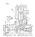
- FIG. 1 is a cross-sectional view of the expansion valve according to the present invention.
- the expansion valve has a valve body 10 which is substantially prismatic. At the lower area of the valve body 10 is formed an inlet 12 through which a liquid-phase refrigerant from a compressor in a refrigeration cycle is supplied, and the inlet 12 is communicated with a valve chamber 14. In the valve chamber 14, a ball-shaped valve means 40 is disposed facing a valve seat 16. The valve means 40 is supported by a spring 32 via a support member 34.
- a nut member 30 is screwed onto an opening portion of the valve chamber 14 and seals the chamber.
- the spring 32 is pre-compressed, and a seal member 36 is attached to the nut member 30 supporting the valve means 40 via the support member 34 with predetermined spring force to thereby seal the valve chamber 14.
- the refrigerant in the valve chamber 14 travels through an opening portion between the valve means 40 and valve seat 16 and flows out into a first passage 20.
- the first passage 20 sends the refrigerant through an outlet toward an evaporator not shown.
- the refrigerant in the second passage is sent through a gap 52 into a power element 60 which is a valve drive mechanism attached to an upper portion of the valve body 10.
- the power element 60 has a body 62 attached to the valve body 10 via a screw portion 64. It further has a diaphragm 70 sandwiched by the body 62, which defines an upper chamber 72a and a lower chamber 72b. A working fluid is filled in the upper chamber 72a and sealed by a plug 66.
- the diaphragm 70 is supported by a stopper 74.
- the stopper 74 is formed either integrally with or separately from a valve shaft 80.
- One end of the valve shaft 80 is in contact with the valve means 40.
- a seal member 82 is fit to the outer circumference of the valve shaft 80.
- valve shaft 80 moves according to the operation position of the diaphragm 70 determined to correspond to the pressure and temperature of the refrigerant returning from the evaporator and flowing through the second passage 50, adjusting the gap formed between the valve means 40 and the valve seat 16.
- the gap between the valve means 40 and the valve seat 16 is widened, causing a large amount of refrigerant to be supplied to the evaporator.
- the thermal load is small, the flow rate of the refrigerant is reduced.
- a solenoid relief valve the entire body of which is denoted by reference number 100, has a relief valve body 150 attached to the side wall of the valve body 10 of the expansion valve.
- the relief valve body 150 is screwed onto and fixed to an inner screw portion disposed to an opening of a refrigerant chamber 26 formed to the side wall of the expansion valve body 10.
- the expansion valve body 10 has a refrigerant passage 24 that communicates the valve chamber 14 into which high-pressure refrigerant is introduced and the refrigerant chamber 26.
- the refrigerant chamber 26 communicates via a relief valve seat 28 with a refrigerant passage 20 leading to an evaporator (not shown).
- a relief valve chamber 164 is formed to the relief valve body 150, and a relief valve means 160 is inserted thereto in a slidable manner.
- the relief valve 160 has a valve member 162 made of Teflon (registered trademark) or elastic material such as rubber disposed at an end thereof, that comes into contact with a relief valve seat 28.
- the relief valve means 160 has a hexagonal cylinder-shaped cross-section for example, as shown in A-A cross-sectional view, wherein corner portions 160a are in contact with the inner circumference portion of the relief valve chamber 164 while flat portions 160b define gaps with the inner circumference portion of the relief valve chamber 164.
- the high-pressure refrigerant introduced into the refrigerant chamber 26 of the expansion valve body 10 passes through the gaps mentioned above and flows into the relief valve chamber 164.
- the high-pressure refrigerant pushes the relief valve means 160, by which the valve member 162 is pressed against the relief valve seat 28 and closes the space between the refrigerant chamber 26 and the refrigerant passage 20 leading to the evaporator 26.
- a coil spring 165 is disposed in the relief valve chamber 164 for pressing the relief valve means 160 against the relief valve seat 28 and closing the valve when the refrigeration cycle is stopped.
- An attractor 130 is inserted to a pipe member 105 attached to the upper portion of the relief valve body 150, and on the upper end of the attractor 130 is fixed a coil housing 110 through an attachment screw 112.
- Amagnet coil 120 is attached to the coil housing 110, which is connected via an electric circuit not shown to a control unit.
- a plunger 140 is slidably inserted to the interior of the pipe member 105. Between the relief valve body 150 and the plunger 140 is formed a pilot valve chamber 156. The high-pressure refrigerant of the relief valve chamber 164 is introduced via a passage 154 into the pilot valve chamber 156.
- a pilot valve means 142 is attached to the end of the plunger 140 and comes into contact with a pilot valve seat 152.
- the attractor 130 supports a coil spring 134 via a support member 132, and the coil spring 134 regularly biases the plunger 140 toward the pilot valve seat 152. This spring force enables the pilot valve means 142 to shut the valve of the pilot valve seat 152.
- the high-pressure refrigerant in the pilot valve chamber 156 is introduced through a passage 144 formed to the plunger 140 to the back side of the pilot valve means 142, so as to more reliably close the valve of the pilot valve seat 152.
- the high-pressure refrigerant in the pilot valve chamber 156 is rapidly relieved through a passage 158 toward the atmosphere.
- the pressure within the relief valve chamber 164 drops, and the valve member 162 of the relief valve means 160 is pushed up by the high-pressure refrigerant in the refrigerant chamber 26 and in the passage 20 leading to the evaporator and is separated from the relief valve seat 28, by which the valve is opened.
- the signal used for supplying electricity to the solenoid valve can be, for example, a signal from an acceleration sensor for detecting the occurrence of collision of a vehicle equipped with an air conditioner having the refrigeration cycle containing the present expansion valve, or a signal froma refrigerant sensor for detecting a leakage of the refrigerant from the refrigeration cycle.
- the acceleration sensor canbe used commonlywith a sensor for operating an air bag.
Abstract
Description
Claims (4)
- An expansion valve having a solenoid relief valve equipped in an air conditioner for decompressing and expanding a refrigerant and supplying the same to an evaporator, the expansion valve comprising:a valve chamber into which a high-pressure refrigerant from a compressor enters;a first passage through which flows the refrigerant traveling toward the evaporator;a second passage through which flows the refrigerant returning from the evaporator toward the compressor;a valve seat disposed between the valve chamber and the first passage;a valve body having a refrigerant chamber disposed in parallel to the valve seat and communicating the valve chamber and the first passage;a valve means capable of coming into contact with and separating from the valve seat;a power element which is a driving mechanism for the valve means; anda solenoid relief valve disposed between the refrigerant chamber and the first passage.
- The expansion valve having a solenoid relief valve according to claim 1, wherein the solenoid relief valve comprises:a relief valve body having a relief valve chamber;a relief valve means inserted to the relief valve chamber in a slidable manner for opening and closing a relief valve seat;a pilot valve disposed between the relief valve chamber and a passage opening to an atmosphere;a plunger for opening and closing the pilot valve; anda magnet coil for operating the plunger.
- The expansion valve having a solenoid relief valve according to claim 2, wherein the relief valve means has a cross-sectional shape that allows the high-pressure refrigerant in the refrigeration chamber to be introduced into the relief valve chamber.
- The expansion valve having a solenoid relief valve according to claim 2, wherein the pilot valve comprises:a pilot valve chamber communicated with the relief valve chamber;a pilot valve seat disposed between the pilot valve chamber and the passage opening to the atmosphere;a plunger having a pilot valve means for opening and closing the pilot valve seat;a pipe member having the plunger inserted thereto;an attractor fixed to an end of the pipe member;a compression coil spring disposed between the attractor and the plunger; anda magnet coil attached to an outer circumference of the pipe member.
Applications Claiming Priority (2)
| Application Number | Priority Date | Filing Date | Title |
|---|---|---|---|
| JP2003376444A JP4255807B2 (en) | 2003-11-06 | 2003-11-06 | Expansion valve with electromagnetic relief valve |
| JP2003376444 | 2003-11-06 |
Publications (3)
| Publication Number | Publication Date |
|---|---|
| EP1530013A2 true EP1530013A2 (en) | 2005-05-11 |
| EP1530013A3 EP1530013A3 (en) | 2007-12-26 |
| EP1530013B1 EP1530013B1 (en) | 2017-01-11 |
Family
ID=34431293
Family Applications (1)
| Application Number | Title | Priority Date | Filing Date |
|---|---|---|---|
| EP04026014.3A Expired - Fee Related EP1530013B1 (en) | 2003-11-06 | 2004-11-03 | Expansion valve having solenoid relief valve |
Country Status (5)
| Country | Link |
|---|---|
| US (1) | US7299646B2 (en) |
| EP (1) | EP1530013B1 (en) |
| JP (1) | JP4255807B2 (en) |
| KR (1) | KR101049919B1 (en) |
| CN (1) | CN100363658C (en) |
Cited By (5)
| Publication number | Priority date | Publication date | Assignee | Title |
|---|---|---|---|---|
| EP1715262A2 (en) * | 2005-04-18 | 2006-10-25 | Behr GmbH & Co. KG | Safety device preventing overpressure for a refrigerant circuit |
| WO2007087992A1 (en) | 2006-02-02 | 2007-08-09 | Thomas Magnete Gmbh | Expansion valve for an air conditioner |
| DE102015114340A1 (en) * | 2015-08-28 | 2017-03-02 | Halla Visteon Climate Control Corporation | Combining multi-port valve |
| WO2020205430A1 (en) * | 2019-04-01 | 2020-10-08 | Parker-Hannifin Corporation | Power element for refrigerant modulating valve |
| EP4220038A1 (en) * | 2021-03-22 | 2023-08-02 | TGK CO., Ltd. | Control valve |
Families Citing this family (16)
| Publication number | Priority date | Publication date | Assignee | Title |
|---|---|---|---|---|
| KR20070046323A (en) * | 2005-10-31 | 2007-05-03 | 한라공조주식회사 | Expansion valve for rear car air conditioner |
| JP5198337B2 (en) * | 2009-03-25 | 2013-05-15 | ホシザキ電機株式会社 | Automatic ice machine |
| US8191376B2 (en) * | 2009-06-18 | 2012-06-05 | Trane International Inc. | Valve and subcooler for storing refrigerant |
| US8382035B2 (en) * | 2009-09-09 | 2013-02-26 | Honeywell International Inc. | Poppet valve for cabin pressure control systems |
| EP2309213B1 (en) * | 2009-10-12 | 2013-05-01 | LG Electronics Inc. | Air conditioning system and method for controlling operation thereof |
| CN102313023B (en) * | 2010-06-30 | 2013-01-02 | 浙江三花汽车零部件股份有限公司 | Electromagnetic valve and automobile air conditioning system |
| CN102434681B (en) * | 2011-09-29 | 2013-05-08 | 浙江盾安人工环境股份有限公司 | Electromagnetic-drive expansion valve |
| CN103256421B (en) * | 2013-03-07 | 2015-03-25 | 荆门市广恒机电设备有限公司 | Electromagnetic zone control valve for high-pressure water mist extinguishing system |
| EP2952834A1 (en) * | 2014-06-04 | 2015-12-09 | Danfoss A/S | Electronic expansion valve and methods for calibrating an electronic expansion valve |
| CN107356022B (en) * | 2016-05-10 | 2021-02-23 | 比亚迪股份有限公司 | Heat pump air conditioning system and electric automobile |
| EP3453929A4 (en) * | 2016-05-10 | 2019-05-01 | BYD Company Limited | Expansion switch valve |
| JP6478958B2 (en) * | 2016-09-02 | 2019-03-06 | 株式会社不二工機 | Control valve |
| CN108253160A (en) * | 2016-12-29 | 2018-07-06 | 比亚迪股份有限公司 | Expand switch valve |
| KR102518716B1 (en) * | 2018-07-16 | 2023-04-05 | 현대자동차주식회사 | Solenoid valve for controlling supply of gas |
| JP6729674B2 (en) * | 2018-12-21 | 2020-07-22 | ダイキン工業株式会社 | Refrigeration equipment for containers |
| JP7190775B2 (en) * | 2019-04-17 | 2022-12-16 | 株式会社不二工機 | Solenoid valve integrated expansion valve |
Citations (2)
| Publication number | Priority date | Publication date | Assignee | Title |
|---|---|---|---|---|
| EP1040947A2 (en) | 1999-04-01 | 2000-10-04 | Otto Egelhof GmbH & Co. | Vehicle air conditioner |
| EP1052463A2 (en) | 1999-05-11 | 2000-11-15 | Fujikoki Corporation | Expansion valve |
Family Cites Families (18)
| Publication number | Priority date | Publication date | Assignee | Title |
|---|---|---|---|---|
| US4073464A (en) * | 1976-08-24 | 1978-02-14 | Chemetron Corporation | Cylinder valve for gas fire extinguishing system |
| JPS58167852A (en) * | 1982-03-30 | 1983-10-04 | Toshiba Corp | Sterling engine drive air conditioner |
| KR930003627B1 (en) * | 1990-12-07 | 1993-05-08 | 현대자동차 주식회사 | Fire preventing system in a vehicle fuel tank |
| JP3237218B2 (en) * | 1992-08-05 | 2001-12-10 | 株式会社日立製作所 | Air conditioner |
| JP3397862B2 (en) * | 1993-11-30 | 2003-04-21 | 株式会社デンソー | Expansion valve with solenoid valve |
| JPH07301461A (en) * | 1994-05-02 | 1995-11-14 | Zexel Corp | Cooling cycle |
| JP3426791B2 (en) * | 1995-06-16 | 2003-07-14 | 三菱重工業株式会社 | Temperature type automatic expansion valve |
| JPH1016542A (en) * | 1996-06-28 | 1998-01-20 | Pacific Ind Co Ltd | Receiver having expansion mechanism |
| US5915665A (en) | 1997-10-27 | 1999-06-29 | Kohler Co. | Latching solenoid valve |
| JPH11173705A (en) | 1997-12-09 | 1999-07-02 | Tgk Co Ltd | Expansion valve with bypass pipeline for refrigeration cycle |
| JP3882299B2 (en) * | 1997-12-22 | 2007-02-14 | 株式会社デンソー | Expansion valve with integrated solenoid valve |
| JP3775920B2 (en) | 1998-04-23 | 2006-05-17 | 松下電器産業株式会社 | Air conditioner |
| JP2000028212A (en) * | 1998-07-14 | 2000-01-28 | Matsushita Electric Ind Co Ltd | Refrigerating cycle device |
| DE19852127B4 (en) * | 1998-11-12 | 2008-09-11 | Behr Gmbh & Co. Kg | Expansion member and usable valve unit |
| US6334324B1 (en) * | 1998-11-20 | 2002-01-01 | Zexel Valeo Climate Control Corporation | Expansion device |
| JP4348571B2 (en) * | 1999-01-18 | 2009-10-21 | 株式会社ヴァレオサーマルシステムズ | Refrigeration cycle |
| JP4576076B2 (en) * | 2001-08-22 | 2010-11-04 | 株式会社不二工機 | Expansion valve with integrated solenoid valve |
| JP4067936B2 (en) * | 2002-10-29 | 2008-03-26 | 株式会社不二工機 | Expansion valve with integrated solenoid valve |
-
2003
- 2003-11-06 JP JP2003376444A patent/JP4255807B2/en not_active Expired - Fee Related
-
2004
- 2004-10-27 US US10/973,247 patent/US7299646B2/en active Active
- 2004-11-03 EP EP04026014.3A patent/EP1530013B1/en not_active Expired - Fee Related
- 2004-11-03 CN CNB2004100884935A patent/CN100363658C/en not_active Expired - Fee Related
- 2004-11-05 KR KR1020040089733A patent/KR101049919B1/en active IP Right Grant
Patent Citations (2)
| Publication number | Priority date | Publication date | Assignee | Title |
|---|---|---|---|---|
| EP1040947A2 (en) | 1999-04-01 | 2000-10-04 | Otto Egelhof GmbH & Co. | Vehicle air conditioner |
| EP1052463A2 (en) | 1999-05-11 | 2000-11-15 | Fujikoki Corporation | Expansion valve |
Cited By (7)
| Publication number | Priority date | Publication date | Assignee | Title |
|---|---|---|---|---|
| EP1715262A2 (en) * | 2005-04-18 | 2006-10-25 | Behr GmbH & Co. KG | Safety device preventing overpressure for a refrigerant circuit |
| EP1715262A3 (en) * | 2005-04-18 | 2008-07-02 | Behr GmbH & Co. KG | Safety device preventing overpressure for a refrigerant circuit |
| WO2007087992A1 (en) | 2006-02-02 | 2007-08-09 | Thomas Magnete Gmbh | Expansion valve for an air conditioner |
| DE102015114340A1 (en) * | 2015-08-28 | 2017-03-02 | Halla Visteon Climate Control Corporation | Combining multi-port valve |
| DE102015114340B4 (en) | 2015-08-28 | 2019-01-17 | Halla Visteon Climate Control Corporation | Combining multi-port valve |
| WO2020205430A1 (en) * | 2019-04-01 | 2020-10-08 | Parker-Hannifin Corporation | Power element for refrigerant modulating valve |
| EP4220038A1 (en) * | 2021-03-22 | 2023-08-02 | TGK CO., Ltd. | Control valve |
Also Published As
| Publication number | Publication date |
|---|---|
| EP1530013B1 (en) | 2017-01-11 |
| US20050097920A1 (en) | 2005-05-12 |
| EP1530013A3 (en) | 2007-12-26 |
| KR101049919B1 (en) | 2011-07-15 |
| CN100363658C (en) | 2008-01-23 |
| JP2005140381A (en) | 2005-06-02 |
| JP4255807B2 (en) | 2009-04-15 |
| US7299646B2 (en) | 2007-11-27 |
| KR20050043697A (en) | 2005-05-11 |
| CN1614268A (en) | 2005-05-11 |
Similar Documents
| Publication | Publication Date | Title |
|---|---|---|
| US7299646B2 (en) | Expansion valve having solenoid relief valve | |
| CN111316028B (en) | Capacity control valve and control method for capacity control valve | |
| EP1052463B1 (en) | Expansion valve | |
| US5826438A (en) | Expansion valve integrated with electromagnetic valve and refrigeration cycle employing the same | |
| CN111417780B (en) | Capacity control valve and control method for capacity control valve | |
| CN111512046B (en) | Capacity control valve and control method for capacity control valve | |
| US20060005556A1 (en) | Flow rate control valve | |
| US20070251586A1 (en) | Electro-pneumatic control valve with microvalve pilot | |
| US7036744B2 (en) | Solenoid valve-equipped expansion valve | |
| JP4848548B2 (en) | Expansion valve with solenoid valve | |
| US6634567B2 (en) | Expansion valve unit having pressure detecting function | |
| US5639224A (en) | Device for monitoring pressure or temperature in a compressor | |
| KR20050071659A (en) | Compressor | |
| US6892953B2 (en) | Expansion valve integrated with solenoid valve | |
| JP4086682B2 (en) | Expansion device | |
| US7611335B2 (en) | Two set-point pilot piston control valve | |
| EP0874202B1 (en) | Expansion valve integrated with electromagnetic valve and refrigeration cycle employing the same | |
| CN111601970B (en) | Capacity control valve and control method for capacity control valve | |
| JP2003336941A (en) | Outflow prevention device | |
| JPH0735874U (en) | solenoid valve | |
| JP4923331B2 (en) | Hydraulic pressure accumulator | |
| JPH0334613Y2 (en) | ||
| JP2007263092A (en) | Control valve for compressor | |
| JPH11325659A (en) | Expansion valve fitted with solenoid valve | |
| JPS6022095A (en) | Compressor |
Legal Events
| Date | Code | Title | Description |
|---|---|---|---|
| PUAI | Public reference made under article 153(3) epc to a published international application that has entered the european phase |
Free format text: ORIGINAL CODE: 0009012 |
|
| AK | Designated contracting states |
Kind code of ref document: A2 Designated state(s): AT BE BG CH CY CZ DE DK EE ES FI FR GB GR HU IE IS IT LI LU MC NL PL PT RO SE SI SK TR |
|
| AX | Request for extension of the european patent |
Extension state: AL HR LT LV MK YU |
|
| PUAL | Search report despatched |
Free format text: ORIGINAL CODE: 0009013 |
|
| AK | Designated contracting states |
Kind code of ref document: A3 Designated state(s): AT BE BG CH CY CZ DE DK EE ES FI FR GB GR HU IE IS IT LI LU MC NL PL PT RO SE SI SK TR |
|
| AX | Request for extension of the european patent |
Extension state: AL HR LT LV MK YU |
|
| 17P | Request for examination filed |
Effective date: 20080317 |
|
| AKX | Designation fees paid |
Designated state(s): DE FR GB IT |
|
| 17Q | First examination report despatched |
Effective date: 20090323 |
|
| GRAP | Despatch of communication of intention to grant a patent |
Free format text: ORIGINAL CODE: EPIDOSNIGR1 |
|
| INTG | Intention to grant announced |
Effective date: 20160923 |
|
| GRAS | Grant fee paid |
Free format text: ORIGINAL CODE: EPIDOSNIGR3 |
|
| GRAA | (expected) grant |
Free format text: ORIGINAL CODE: 0009210 |
|
| AK | Designated contracting states |
Kind code of ref document: B1 Designated state(s): DE FR GB IT |
|
| REG | Reference to a national code |
Ref country code: GB Ref legal event code: FG4D |
|
| REG | Reference to a national code |
Ref country code: DE Ref legal event code: R096 Ref document number: 602004050638 Country of ref document: DE |
|
| REG | Reference to a national code |
Ref country code: DE Ref legal event code: R097 Ref document number: 602004050638 Country of ref document: DE |
|
| PLBE | No opposition filed within time limit |
Free format text: ORIGINAL CODE: 0009261 |
|
| STAA | Information on the status of an ep patent application or granted ep patent |
Free format text: STATUS: NO OPPOSITION FILED WITHIN TIME LIMIT |
|
| REG | Reference to a national code |
Ref country code: FR Ref legal event code: PLFP Year of fee payment: 14 |
|
| 26N | No opposition filed |
Effective date: 20171012 |
|
| REG | Reference to a national code |
Ref country code: FR Ref legal event code: PLFP Year of fee payment: 15 |
|
| PGFP | Annual fee paid to national office [announced via postgrant information from national office to epo] |
Ref country code: DE Payment date: 20191022 Year of fee payment: 16 |
|
| PGFP | Annual fee paid to national office [announced via postgrant information from national office to epo] |
Ref country code: FR Payment date: 20191014 Year of fee payment: 16 Ref country code: IT Payment date: 20191108 Year of fee payment: 16 |
|
| PGFP | Annual fee paid to national office [announced via postgrant information from national office to epo] |
Ref country code: GB Payment date: 20191031 Year of fee payment: 16 |
|
| REG | Reference to a national code |
Ref country code: DE Ref legal event code: R079 Ref document number: 602004050638 Country of ref document: DE Free format text: PREVIOUS MAIN CLASS: F25B0041060000 Ipc: F25B0041300000 |
|
| REG | Reference to a national code |
Ref country code: DE Ref legal event code: R119 Ref document number: 602004050638 Country of ref document: DE |
|
| GBPC | Gb: european patent ceased through non-payment of renewal fee |
Effective date: 20201103 |
|
| PG25 | Lapsed in a contracting state [announced via postgrant information from national office to epo] |
Ref country code: FR Free format text: LAPSE BECAUSE OF NON-PAYMENT OF DUE FEES Effective date: 20201130 Ref country code: IT Free format text: LAPSE BECAUSE OF NON-PAYMENT OF DUE FEES Effective date: 20201103 |
|
| PG25 | Lapsed in a contracting state [announced via postgrant information from national office to epo] |
Ref country code: GB Free format text: LAPSE BECAUSE OF NON-PAYMENT OF DUE FEES Effective date: 20201103 Ref country code: DE Free format text: LAPSE BECAUSE OF NON-PAYMENT OF DUE FEES Effective date: 20210601 |