EP1052463A2 - Expansion valve - Google Patents
Expansion valve Download PDFInfo
- Publication number
- EP1052463A2 EP1052463A2 EP00108900A EP00108900A EP1052463A2 EP 1052463 A2 EP1052463 A2 EP 1052463A2 EP 00108900 A EP00108900 A EP 00108900A EP 00108900 A EP00108900 A EP 00108900A EP 1052463 A2 EP1052463 A2 EP 1052463A2
- Authority
- EP
- European Patent Office
- Prior art keywords
- valve
- passage
- refrigerant
- evaporator
- bypass passage
- Prior art date
- Legal status (The legal status is an assumption and is not a legal conclusion. Google has not performed a legal analysis and makes no representation as to the accuracy of the status listed.)
- Granted
Links
- 239000003507 refrigerant Substances 0.000 claims abstract description 71
- 238000004378 air conditioning Methods 0.000 claims description 9
- 238000005057 refrigeration Methods 0.000 description 9
- 238000005461 lubrication Methods 0.000 description 4
- 230000000149 penetrating effect Effects 0.000 description 2
- 230000007423 decrease Effects 0.000 description 1
- 239000012530 fluid Substances 0.000 description 1
- 239000007791 liquid phase Substances 0.000 description 1
- 239000010687 lubricating oil Substances 0.000 description 1
- 230000007257 malfunction Effects 0.000 description 1
- 239000011347 resin Substances 0.000 description 1
- 229920005989 resin Polymers 0.000 description 1
- 238000007789 sealing Methods 0.000 description 1
Images


Classifications
-
- F—MECHANICAL ENGINEERING; LIGHTING; HEATING; WEAPONS; BLASTING
- F25—REFRIGERATION OR COOLING; COMBINED HEATING AND REFRIGERATION SYSTEMS; HEAT PUMP SYSTEMS; MANUFACTURE OR STORAGE OF ICE; LIQUEFACTION SOLIDIFICATION OF GASES
- F25B—REFRIGERATION MACHINES, PLANTS OR SYSTEMS; COMBINED HEATING AND REFRIGERATION SYSTEMS; HEAT PUMP SYSTEMS
- F25B41/00—Fluid-circulation arrangements
- F25B41/20—Disposition of valves, e.g. of on-off valves or flow control valves
-
- F—MECHANICAL ENGINEERING; LIGHTING; HEATING; WEAPONS; BLASTING
- F25—REFRIGERATION OR COOLING; COMBINED HEATING AND REFRIGERATION SYSTEMS; HEAT PUMP SYSTEMS; MANUFACTURE OR STORAGE OF ICE; LIQUEFACTION SOLIDIFICATION OF GASES
- F25B—REFRIGERATION MACHINES, PLANTS OR SYSTEMS; COMBINED HEATING AND REFRIGERATION SYSTEMS; HEAT PUMP SYSTEMS
- F25B41/00—Fluid-circulation arrangements
- F25B41/30—Expansion means; Dispositions thereof
- F25B41/31—Expansion valves
- F25B41/34—Expansion valves with the valve member being actuated by electric means, e.g. by piezoelectric actuators
-
- F—MECHANICAL ENGINEERING; LIGHTING; HEATING; WEAPONS; BLASTING
- F25—REFRIGERATION OR COOLING; COMBINED HEATING AND REFRIGERATION SYSTEMS; HEAT PUMP SYSTEMS; MANUFACTURE OR STORAGE OF ICE; LIQUEFACTION SOLIDIFICATION OF GASES
- F25B—REFRIGERATION MACHINES, PLANTS OR SYSTEMS; COMBINED HEATING AND REFRIGERATION SYSTEMS; HEAT PUMP SYSTEMS
- F25B41/00—Fluid-circulation arrangements
- F25B41/30—Expansion means; Dispositions thereof
- F25B41/31—Expansion valves
- F25B41/325—Expansion valves having two or more valve members
-
- F—MECHANICAL ENGINEERING; LIGHTING; HEATING; WEAPONS; BLASTING
- F25—REFRIGERATION OR COOLING; COMBINED HEATING AND REFRIGERATION SYSTEMS; HEAT PUMP SYSTEMS; MANUFACTURE OR STORAGE OF ICE; LIQUEFACTION SOLIDIFICATION OF GASES
- F25B—REFRIGERATION MACHINES, PLANTS OR SYSTEMS; COMBINED HEATING AND REFRIGERATION SYSTEMS; HEAT PUMP SYSTEMS
- F25B41/00—Fluid-circulation arrangements
- F25B41/30—Expansion means; Dispositions thereof
- F25B41/31—Expansion valves
- F25B41/33—Expansion valves with the valve member being actuated by the fluid pressure, e.g. by the pressure of the refrigerant
- F25B41/335—Expansion valves with the valve member being actuated by the fluid pressure, e.g. by the pressure of the refrigerant via diaphragms
-
- F—MECHANICAL ENGINEERING; LIGHTING; HEATING; WEAPONS; BLASTING
- F25—REFRIGERATION OR COOLING; COMBINED HEATING AND REFRIGERATION SYSTEMS; HEAT PUMP SYSTEMS; MANUFACTURE OR STORAGE OF ICE; LIQUEFACTION SOLIDIFICATION OF GASES
- F25B—REFRIGERATION MACHINES, PLANTS OR SYSTEMS; COMBINED HEATING AND REFRIGERATION SYSTEMS; HEAT PUMP SYSTEMS
- F25B41/00—Fluid-circulation arrangements
- F25B41/40—Fluid line arrangements
-
- G—PHYSICS
- G05—CONTROLLING; REGULATING
- G05D—SYSTEMS FOR CONTROLLING OR REGULATING NON-ELECTRIC VARIABLES
- G05D23/00—Control of temperature
- G05D23/01—Control of temperature without auxiliary power
- G05D23/12—Control of temperature without auxiliary power with sensing element responsive to pressure or volume changes in a confined fluid
-
- F—MECHANICAL ENGINEERING; LIGHTING; HEATING; WEAPONS; BLASTING
- F25—REFRIGERATION OR COOLING; COMBINED HEATING AND REFRIGERATION SYSTEMS; HEAT PUMP SYSTEMS; MANUFACTURE OR STORAGE OF ICE; LIQUEFACTION SOLIDIFICATION OF GASES
- F25B—REFRIGERATION MACHINES, PLANTS OR SYSTEMS; COMBINED HEATING AND REFRIGERATION SYSTEMS; HEAT PUMP SYSTEMS
- F25B2341/00—Details of ejectors not being used as compression device; Details of flow restrictors or expansion valves
- F25B2341/06—Details of flow restrictors or expansion valves
- F25B2341/068—Expansion valves combined with a sensor
- F25B2341/0683—Expansion valves combined with a sensor the sensor is disposed in the suction line and influenced by the temperature or the pressure of the suction gas
-
- F—MECHANICAL ENGINEERING; LIGHTING; HEATING; WEAPONS; BLASTING
- F25—REFRIGERATION OR COOLING; COMBINED HEATING AND REFRIGERATION SYSTEMS; HEAT PUMP SYSTEMS; MANUFACTURE OR STORAGE OF ICE; LIQUEFACTION SOLIDIFICATION OF GASES
- F25B—REFRIGERATION MACHINES, PLANTS OR SYSTEMS; COMBINED HEATING AND REFRIGERATION SYSTEMS; HEAT PUMP SYSTEMS
- F25B2700/00—Sensing or detecting of parameters; Sensors therefor
- F25B2700/19—Pressures
- F25B2700/191—Pressures near an expansion valve
-
- F—MECHANICAL ENGINEERING; LIGHTING; HEATING; WEAPONS; BLASTING
- F25—REFRIGERATION OR COOLING; COMBINED HEATING AND REFRIGERATION SYSTEMS; HEAT PUMP SYSTEMS; MANUFACTURE OR STORAGE OF ICE; LIQUEFACTION SOLIDIFICATION OF GASES
- F25B—REFRIGERATION MACHINES, PLANTS OR SYSTEMS; COMBINED HEATING AND REFRIGERATION SYSTEMS; HEAT PUMP SYSTEMS
- F25B2700/00—Sensing or detecting of parameters; Sensors therefor
- F25B2700/21—Temperatures
Definitions
- the present invention relates to an expansion valve equipped in an air conditioner mounted on a vehicle for controlling the flow of a refrigerant travelling to an evaporator, wherein a bypass passage formed to the expansion valve is opened by an electromagnetic valve when the expansion valve is in a closed state, circulating a minimum amount of refrigerant so as to secure the lubrication of a compressor and the like constituting the refrigerant cycle.
- the expansion valve equipped in an air conditioner of a vehicle includes a valve chamber for controlling the flow of the refrigerant into which the refrigerant being supplied from a compressor is introduced, a first passage for guiding the refrigerant exiting the valve chamber toward an evaporator, and a second passage through which the refrigerant returning from the evaporator travels.
- a shaft-like valve drive member having a heat sensing function is equipped in the second passage for sensing the refrigerant temperature flowing thruogh the passage and for transmitting the sensed temperature to a valve drive mechanism called a power element. Further, the distance between a valve means and a valve seat of the expansion valve is operated so as to control the flow of the refrigerant.
- the present invention aims at providing an expansion valve capable of circulating a minimum amount of refrigerant even when the air-conditioning load is low.
- the present invention provides an expansion valve equipped in an air conditioner for decompressing and expanding a refrigerant and supplying the same to an evaporator, wherein a valve body comprising a first passage through which said refrigerant being transferred to said evaporator travels, a second passage through which said refrigerant returning from said evaporator toward a compressor travels, and a valve chamber equipped in said first passage into which the refrigerant enters, is further equipped with a bypass passage for supplying said refrigerant from said valve chamber to said compressor, and an electromagnetic valve for opening and closing said bypass passage, said electromagnetic valve being operated so as to open said bypass passage according to the output from a sensing means for detecting a predetermined air-conditioning load.
- bypass passage communicates the valve chamber and the first passage. Moreover, the bypass passage communicates the valve chamber and the second passage.
- the sensing means is a pressure sensor or a temperature sensor.
- the expansion valve according to the present invention is equipped in an air conditioner for decompressing and expanding a refrigerant and supplying the same to an evaporator, said expansion valve including a valve body comprising a first passage through which said refrigerant being transferred to said evaporator travels and a second passage through which said refrigerant returning from said evaporator travels, a valve chamber equipped in said first passage into which said refrigerant enters, a bypass passage for communicating said valve chamber and said first or said second passage, an electromagnetic valve for opening or closing said bypass passage, and a pressure switch equipped to said second passage, wherein said pressure switch detects the reduction of pressure of said refrigerant inside said second passage, and operates said electromagnetic valve to open said bypass passage.
- the electromagnetic valve is equipped with a plunger and a pilot valve being opened and closed by the end portion of said plunger, said pilot valve being operated to open or close a conduit equipped within said bypass passage.
- the expansion valve according to the present invention defined as above realizes a valve which is capable of supplying a minimum amount of refrigerant to the refrigeration cycle even when the valve is nearly or completely closed.
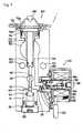
- FIG. 1 is a cross-sectional view of the expansion valve according to the present invention showing a refrigerant passage in cross-section
- FIG. 2 is a cross-sectional view corresponding to the right side view of FIG. 1
- FIG. 3 is a right side view of FIG. 2.
- the expansion valve shown as a whole by reference number 1 has a substantially prismatic-shaped valve body 10. To the lower portion of the valve body 10 is equipped an entrance hole 12 through which a liquid-phase refrigerant supplied from a compressor of a refrigeration cycle travels. The entrance hole 12 is communicated to a valve chamber 14. A valve member 40 is supported through a support member 34 by a spring 32.
- a nut member 30 is screwed and fixed to the opening portion formed to the valve chamber 14.
- the spring 32 is pre-loaded, which supports the valve member 40 through the support member 34 with a predetermined spring force.
- a seal member 36 is mounted onto the nut member 30 to seal the valve chamber 14.
- the refrigerant in the valve chamber 14 travels through the opening portion between the valve member 40 and a valve seat 16 toward a first passage 20.
- the first passage 20 is communicated through an exit hole 22 to an evaporator not shown.
- the refrigerant returning from the evaporator travels through a second passage 50 equipped to the valve body 10, and is circulated again to the compressor not shown.
- the refrigerant in the second passage is sent through a gap 52 toward a power element 60 mounted to the upper portion of the valve body 10, which acts as a driving mechanism of the valve member.
- the power element 60 comprises a body 62 which is mounted to the valve body 10 by a screw portion 64. Further, the element 60 comprises a diaphragm 70 positioned inside the body 62, which defines an upper chamber 72a and a lower chamber 72b. A working fluid is filled inside the upper chamber 72, and sealed by a plug 66.
- the diaphragm 70 is supported by a stopper 74.
- the stopper 74 is formed either integrally with a heat sensing shaft 80, or separately from the shaft 80.
- the heat sensing shaft 80 is for transmitting the temperature of a refrigerant flowing through the second passage 50 to the power element 60.
- a resin 82 having low heat conductivity may be coated to the outer surface of the heat sensing shaft 80, so as to adjust the shaft 80 to have the necessary heat conductivity.
- a valve drive member 90 is contacted to the lower area of the heat sensing shaft 80, which biases the valve member 40 in the direction separating from the valve seat 16.
- the heat sensing shaft 80 is equipped with an o-ring 86 acting as a sealing member preventing communication between the first passage 20 and the second passage 50.
- the expansion valve 1 is formed as explained above, so according to the operating position of the diaphragm 70 set according to the pressure and the temperature of the refrigerant traveling through the second passage 50, the heat sensing shaft 80 and the valve member driving element 90 is moved, and the gap between the valve member 40 and the valve seat 16 is adjusted.
- valve member 40 When the heat load is extremely small, the valve member 40 is either in a closed state or a nearly closed state, and there is fear that the refrigerant circulating through the whole refrigeration cycle may be insufficient to lubricate the compressor and the like sufficiently.
- the expansion valve according to the present invention is equipped with a function to supply the minimum necessary amount of refrigerant through a bypass passage toward the evaporator even when the valve member is in a closed state or in a nearly closed state.
- an electromagnetic valve 100 and a pressure switch 200 As shown in FIGS. 2 and 3, to the side surface of the valve body 10 are mounted an electromagnetic valve 100 and a pressure switch 200.
- the electromagnetic valve 100 comprises a casing 110 and amounting member 140 connected to the casing 110.
- the mounting member 140 is fixed through a screw portion to an opening 26 with a bottom formed to the valve body 10.
- the opening 26 with a bottom is communicated through a narrow hole 24 to the valve chamber 14.
- the refrigerant supplied to the valve chamber 14 is introduced to the opening 26 with a bottom through the narrow hole 24, and a bypass passage to the first passage 20 is formed through a passage 27.
- the electromagnetic valve 100 comprises a coil 120 placed inside the casing 110, and power is supplied thereto through a cord 122.
- a cylinder 124 is positioned in the center area of the casing 110, and a plunger 130 is slidably inserted thereto.
- a stopper 132 is fixed to the outside of the cylinder by a screw 136. The stopper 132 biases the plunger 130 through a spring 134 so that the plunger is biased away from the stopper 132 regularly.
- a pilot valve 150 is slidably mounted to the tip of the plunger 130.
- the pilot valve 150 has a valve hole 152 formed to the center area thereof.
- a pipe-like conduit 28 is formed to the center of the opening 26 with a bottom.
- a passage 27 of the inner diameter of the conduit 28 communicates the opening 26 and the first refrigerant passage 20 of the valve body.
- the pilot valve 150 is regularly pressed by the plunger 130, and the plunger 130 shuts the valve hole 152 of the pilot valve 150 with its tip portion. Refrigerant from the opening 26 is introduced to a backing pressure chamber 160 formed outside the pilot valve 150, and by the backing pressure, the pilot valve 150 is pressed against the opening of the conduit 28 and closes its passage 27.
- the plunger 130 When power is supplied to the coil 120 of the electromagnetic valve 100, the plunger 130 is pulled back toward the stopper 132 by the magnetic force of the coil 120.
- the tip of the plunger 130 moves away from the valve hole 152 of the pilot valve 150, the valve hole 152 is opened, and the refrigerant in the backing pressure chamber 160 travels through the valve hole 152 into the passage 27 of the conduit 28, and the pressure difference is reduced.
- the pilot valve 150 thereby moves away from the end of the conduit 28, and the refrigerant in the opening 26 flows toward the first passage 20.
- the refrigerant may be supplied to the evaporator even when the valve means 40 is in a position closing the valve seat 16.
- An opening 54 communicated to the second refrigerant passage 50 is formed to the valve body 10, and a pressure switch 200 is mounted thereto.
- the pressure switch 200 comprises a mounting base 210 and a switch case 220, and the switch 200 is screwed onto the opening 54 through a seal member 214 of the mounting base 210.
- the mounting base 210 comprises a penetrating hole 212, through which the refrigerant in the second passage 50 travels.
- a fixed contact 250 and a movable contact 262 supported by a spring 260 is mounted inside the switch case 220.
- a diaphragm 230 sandwiched inside the switch case 220 operates the spring 260 through a working member 242 mounted slidably to the supporting member 240.
- the refrigerant in the second passage 50 of the valve body 10 is introduced through the opening 54 and the penetrating hole 212 of the mounting base 210 to a pressure chamber 232 formed to one side of the diaphragm.
- a pressure chamber 232 formed to one side of the diaphragm.
- the valve member 40 moves in the direction closing the valve, and the pressure of the refrigerant flowing through the second passage 50 decreases.
- the diaphragm 230 of the pressure switch 200 moves toward the left side of the drawing.
- the spring 260 moves the movable contact 262 so that it contacts the fixed contact 250.
- reference numbers 101 and 102 denote bolt holes for mounting the expansion valve to a predetermined position.
- FIG. 4 is a cross-sectional view showing such embodiment of the present invention, wherein the change in pressure during low load is sensed before opening the bypass passage. That is, the pressure switch utilized in the embodiment shown in FIG. 2 is not used for operating the electromagnetic valve.
- the same reference numbers as FIG. 2 denote the same or equivalent members.
- the change in pressure is sensed by a pressure sensor (not shown) which is for example mounted on a discharge pipe of a compressor for sensing the discharge pressure of the compressor.
- the sensed result is outputted to a controller (not shown), where it is determined whether the output is a predetermined air-conditioning load or not.
- the output from the controller is inputted to the electromagnetic valve 100, and power is supplied to the electromagnetic valve 100. After the power is supplied, the refrigerant flows through a bypass passage into the first passage by the same operation as the valve shown in FIG. 2.
- the present invention may also be applied to a valve where the change in temperature during the low load is detected, instead of the change in pressure detected by the pressure sensor explained above, for opening the bypass passage.
- a temperature sensor (not shown) for sensing the temperature at the blow-out opening of the air conditioner on a vehicle and the like may be equipped to the electromagnetic valve 100, and the output from the temperature sensor is inputted to a controller (not shown). It is determined by the controller whether the air conditioning load is in a predetermined range or not, and if the load is in a predetermined range, the output from the controller is inputted to the electromagnetic valve 100, and power is supplied to the valve 100. After that, similar to the operation of FIG. 2, the refrigerant will be flown into the first passage through the bypass passage.
- a bypass passage communicating to the first passage is formed to supply the refrigerant to the evaporator.
- the invention is not limited to such example, and may also be applied to cases where the bypass passage is communicated to the second passage, circulating the refrigerant without supplying the refrigerant to the evaporator.
- FIG. 5 is a cross-sectional view showing such embodiment of the present invention, wherein a passage 56 for communicating the second passage 50 and the bypass passage is formed within the valve body 10.
- the same reference numbers as the embodiment shown in FIG. 4 denote the same or equivalent members.
- the output from the controller is inputted to the electromagnetic valve 100, and power is supplied to the valve 100.
- refrigerant flows through a bypass passage formed by the narrow hole 24, the opening 26 with a bottom and the passage 27, and travels through a passage 56 toward the second passage 50.
- a pressure switch 200 may be utilized in the embodiment of FIG. 5, similarly as in the embodiment of FIG. 2. That is, a pressure switch 200 may be mounted to the valve body 10 through a mounting base 210, and when the contacts of the pressure switch 200 is closed, the refrigerant flows through the passage 56 into the second passage 50 by the same operation as the embodiment of FIG. 2.
- the minimum necessary amount of refrigerant may be circulated through the bypass passage even when the air-conditioning load becomes very low and the valve is in a closed or nearly closed state. Therefore, the present expansion valve prevents the amount of refrigerant circulating in the refrigeration cycle from becoming too small, which may lead to insufficient lubrication of the compressor and the like.
Abstract
Description
Claims (7)
- An expansion valve equipped in an air conditioner for decompressing and expanding a refrigerant and supplying the same to an evaporator, wherein:a valve body comprising a first passage through which said refrigerant being transferred to said evaporator travels, a second passage through which said refrigerant returning from said evaporator toward a compressor travels, and a valve chamber equipped in said first passage into which said refrigerant enters, is further equipped with a bypass passage for supplying said refrigerant from said valve chamber to said compressor, and an electromagnetic valve for opening and closing said bypass passage, said electromagnetic valve being operated so as to open said bypass passage according to the output from a sensing means for detecting a predetermined air-conditioning load.
- An expansion valve according to claim 1, wherein said bypass passage communicates said valve chamber and said first passage.
- An expansion valve according to claim 2, wherein said bypass passage communicates said valve chamber and said second passage.
- An expansion valve according to claim 2 or claim 3, wherein said sensing means is a pressure sensor.
- An expansion valve according to claim 2 or claim 3, wherein said sensing means is a temperature sensor.
- An expansion valve equipped in an air conditioner for decompressing and expanding a refrigerant and supplying the same to an evaporator, said expansion valve comprising:a valve body including a first passage through which said refrigerant being transferred to said evaporator travels and a second passage through which said refrigerant returning from said evaporator travels, a valve chamber formed to said first passage into which said refrigerant enters, a bypass passage for communicating said valve chamber and said first or said second passage, an electromagnetic valve for opening or closing said bypass passage, and a pressure switch equipped to said second passage; whereinsaid pressure switch detects the reduction of pressure of said refrigerant inside said second passage, and operates said electromagnetic valve to open said bypass passage.
- An expansion valve according to claim 6, wherein said electromagnetic valve is equipped with a plunger and a pilot valve being opened and closed by the end portion of said plunger, said pilot valve being operated to open or close a conduit formed within said bypass passage.
Applications Claiming Priority (4)
| Application Number | Priority Date | Filing Date | Title |
|---|---|---|---|
| JP13031199 | 1999-05-11 | ||
| JP13031199 | 1999-05-11 | ||
| JP27857099 | 1999-09-30 | ||
| JP27857099A JP4153133B2 (en) | 1999-05-11 | 1999-09-30 | Expansion valve |
Publications (3)
| Publication Number | Publication Date |
|---|---|
| EP1052463A2 true EP1052463A2 (en) | 2000-11-15 |
| EP1052463A3 EP1052463A3 (en) | 2002-05-22 |
| EP1052463B1 EP1052463B1 (en) | 2006-06-14 |
Family
ID=26465475
Family Applications (1)
| Application Number | Title | Priority Date | Filing Date |
|---|---|---|---|
| EP00108900A Expired - Lifetime EP1052463B1 (en) | 1999-05-11 | 2000-04-27 | Expansion valve |
Country Status (6)
| Country | Link |
|---|---|
| US (1) | US6233956B1 (en) |
| EP (1) | EP1052463B1 (en) |
| JP (1) | JP4153133B2 (en) |
| KR (1) | KR100706970B1 (en) |
| CN (1) | CN1141540C (en) |
| DE (1) | DE60028656T2 (en) |
Cited By (9)
| Publication number | Priority date | Publication date | Assignee | Title |
|---|---|---|---|---|
| EP1375215A3 (en) * | 2002-06-26 | 2004-06-16 | Delphi Technologies, Inc. | Thermostatic expansion valve and air conditioning system for low refrigerant charge |
| EP1519128A2 (en) * | 2003-09-25 | 2005-03-30 | TGK Co., Ltd. | Refrigeration cycle |
| EP1380801A3 (en) * | 2002-07-11 | 2005-05-04 | TGK CO., Ltd. | Expansion valve |
| EP1530013A2 (en) | 2003-11-06 | 2005-05-11 | Fujikoki Corporation | Expansion valve having solenoid relief valve |
| EP1435495A3 (en) * | 2003-01-06 | 2006-03-22 | TGK Co., Ltd. | Switching valve |
| WO2006042544A1 (en) * | 2004-10-21 | 2006-04-27 | Danfoss A/S | Valve for use in a refrigeration system |
| WO2007028499A1 (en) * | 2005-09-06 | 2007-03-15 | Behr Gmbh & Co. Kg | Expansion valve |
| FR2912495A1 (en) * | 2007-02-14 | 2008-08-15 | Valeo Systemes Thermiques | Lever component for being installed in air conditioning system loop, has regulating device with circulation channel for providing circulation of subcritical refrigerant fluid between inlet and outlet |
| DE102005009831B4 (en) | 2004-03-03 | 2018-08-02 | Otto Egelhof Gmbh & Co. Kg | Method for producing a valve arrangement, in particular for an expansion valve and a valve arrangement |
Families Citing this family (23)
| Publication number | Priority date | Publication date | Assignee | Title |
|---|---|---|---|---|
| US6272869B1 (en) * | 2000-06-30 | 2001-08-14 | American Standard International Inc. | Multiple orifice expansion device |
| US6397614B1 (en) * | 2001-02-22 | 2002-06-04 | Scroll Technologies | Modified expansion device for refrigerant cycle low charge operation |
| JP3995513B2 (en) * | 2001-06-19 | 2007-10-24 | 株式会社デンソー | Expansion valve with pressure detection function |
| JP4067936B2 (en) * | 2002-10-29 | 2008-03-26 | 株式会社不二工機 | Expansion valve with integrated solenoid valve |
| DE102006020457A1 (en) * | 2006-04-28 | 2007-11-15 | Otto Egelhof Gmbh & Co. Kg | Thermal head for expansion valves has a chamber partly limited by a metal side and impervious to substances to be filled with a gas sensitive to temperatures |
| JP5136109B2 (en) * | 2008-02-18 | 2013-02-06 | 株式会社デンソー | Expansion valve |
| CN101684974B (en) * | 2008-09-26 | 2011-04-13 | 王朝阳 | Thermostatic expansion valve with bypass applying in air-conditioning system |
| CN102003849B (en) * | 2010-11-02 | 2012-12-05 | 广东恒基金属制品实业有限公司 | Micro electromechanical silicon expansion valve |
| CN102434681B (en) * | 2011-09-29 | 2013-05-08 | 浙江盾安人工环境股份有限公司 | Electromagnetic-drive expansion valve |
| CN102538319B (en) * | 2012-02-28 | 2014-04-30 | 浙江三花股份有限公司 | Bidirectional throttling electronic expansion valve |
| US9398722B1 (en) * | 2013-09-03 | 2016-07-19 | Mainstream Engineering Corporation | Cold plate with insertable integrated thermostatic expansion device and sensing element |
| CN104567140A (en) * | 2014-12-16 | 2015-04-29 | 合肥三艾汽车配件有限公司 | Expansion valve |
| JP2017150730A (en) * | 2016-02-24 | 2017-08-31 | 株式会社デンソー | Refrigeration cycle device |
| JP6565737B2 (en) * | 2016-02-24 | 2019-08-28 | 株式会社デンソー | Refrigeration cycle equipment |
| JP6700974B2 (en) * | 2016-05-25 | 2020-05-27 | 株式会社不二工機 | Electric expansion valve |
| JP6478958B2 (en) * | 2016-09-02 | 2019-03-06 | 株式会社不二工機 | Control valve |
| CN110732697B (en) * | 2018-07-18 | 2022-11-18 | 浙江三花汽车零部件有限公司 | Expansion valve processing method and expansion valve |
| CN110878996B (en) * | 2018-09-06 | 2021-09-28 | 天津华信机械有限公司 | Multifunctional expansion valve and air conditioning system |
| CN111503293A (en) * | 2019-01-30 | 2020-08-07 | 杭州三花研究院有限公司 | Electronic expansion valve and thermal management assembly |
| CN111720583B (en) * | 2019-03-20 | 2023-07-18 | 浙江三花汽车零部件有限公司 | Control valve, air conditioning system and processing method of control valve |
| CN111720584B (en) * | 2019-03-20 | 2022-09-23 | 浙江三花汽车零部件有限公司 | Control valve and air conditioning system |
| CN111720559B (en) * | 2019-03-20 | 2022-09-23 | 浙江三花汽车零部件有限公司 | Control valve and air conditioning system |
| DE102020204325A1 (en) | 2020-04-02 | 2021-10-07 | Psa Automobiles Sa | Arrangement for the detachable mounting of a sensor |
Citations (5)
| Publication number | Priority date | Publication date | Assignee | Title |
|---|---|---|---|---|
| GB2150273A (en) * | 1983-10-03 | 1985-06-26 | Emhart Ind | Refrigeration systems |
| EP0714004A2 (en) * | 1994-11-24 | 1996-05-29 | SANYO ELECTRIC Co., Ltd. | Refrigerant flow amount control valve and refrigerating apparatus therewith |
| DE19625885A1 (en) * | 1995-06-27 | 1997-01-02 | Nippon Denso Co | Expansion valve with integrated electromagnetic valve for air- conditioning device |
| EP0846927A1 (en) * | 1995-07-13 | 1998-06-10 | Pacific Industrial Co., Ltd. | Thermal type expansion valve |
| US5826438A (en) * | 1996-07-01 | 1998-10-27 | Denso Corporation | Expansion valve integrated with electromagnetic valve and refrigeration cycle employing the same |
Family Cites Families (13)
| Publication number | Priority date | Publication date | Assignee | Title |
|---|---|---|---|---|
| US3150502A (en) * | 1962-07-25 | 1964-09-29 | Singer Co | No-freeze refrigerant control |
| US3363433A (en) * | 1965-08-27 | 1968-01-16 | Jackes Evans Mfg Company | Pilot operated control valve |
| US3839879A (en) * | 1973-05-04 | 1974-10-08 | H Redfern | Defroster with auxiliary heater for display cases |
| JPH0124677Y2 (en) * | 1986-04-19 | 1989-07-26 | ||
| US4688390A (en) * | 1986-05-27 | 1987-08-25 | American Standard Inc. | Refrigerant control for multiple heat exchangers |
| JPH05196324A (en) * | 1992-01-20 | 1993-08-06 | Nippondenso Co Ltd | Expansion valve for refrigerating cycle |
| JP3397862B2 (en) * | 1993-11-30 | 2003-04-21 | 株式会社デンソー | Expansion valve with solenoid valve |
| IT1268893B1 (en) * | 1994-12-21 | 1997-03-13 | Carpigiani Group Ali Srl | COMBINED MACHINE FOR THE ALTERNATIVE PRODUCTION OF GRANITE OR GELATO. |
| KR0159656B1 (en) * | 1995-05-18 | 1999-01-15 | 배순훈 | Reverser for use in an automatic tray changer |
| JP3442949B2 (en) * | 1996-12-13 | 2003-09-02 | 株式会社テージーケー | Refrigeration cycle using variable capacity compressor |
| JP3712827B2 (en) * | 1997-05-26 | 2005-11-02 | 株式会社鷺宮製作所 | Refrigeration system, refrigerant flow rate correction bypass valve and temperature expansion valve |
| JP3882299B2 (en) * | 1997-12-22 | 2007-02-14 | 株式会社デンソー | Expansion valve with integrated solenoid valve |
| JP2000097521A (en) * | 1998-09-24 | 2000-04-04 | Tgk Co Ltd | Inflation valve |
-
1999
- 1999-09-30 JP JP27857099A patent/JP4153133B2/en not_active Expired - Fee Related
-
2000
- 2000-04-06 US US09/543,882 patent/US6233956B1/en not_active Expired - Fee Related
- 2000-04-27 EP EP00108900A patent/EP1052463B1/en not_active Expired - Lifetime
- 2000-04-27 DE DE60028656T patent/DE60028656T2/en not_active Expired - Lifetime
- 2000-04-29 CN CNB001070975A patent/CN1141540C/en not_active Expired - Fee Related
- 2000-05-08 KR KR1020000024432A patent/KR100706970B1/en not_active IP Right Cessation
Patent Citations (5)
| Publication number | Priority date | Publication date | Assignee | Title |
|---|---|---|---|---|
| GB2150273A (en) * | 1983-10-03 | 1985-06-26 | Emhart Ind | Refrigeration systems |
| EP0714004A2 (en) * | 1994-11-24 | 1996-05-29 | SANYO ELECTRIC Co., Ltd. | Refrigerant flow amount control valve and refrigerating apparatus therewith |
| DE19625885A1 (en) * | 1995-06-27 | 1997-01-02 | Nippon Denso Co | Expansion valve with integrated electromagnetic valve for air- conditioning device |
| EP0846927A1 (en) * | 1995-07-13 | 1998-06-10 | Pacific Industrial Co., Ltd. | Thermal type expansion valve |
| US5826438A (en) * | 1996-07-01 | 1998-10-27 | Denso Corporation | Expansion valve integrated with electromagnetic valve and refrigeration cycle employing the same |
Non-Patent Citations (4)
| Title |
|---|
| PATENT ABSTRACTS OF JAPAN vol. 017, no. 633 (M-1513), 24 November 1993 (1993-11-24) & JP 05 196324 A (NIPPONDENSO CO LTD), 6 August 1993 (1993-08-06) * |
| PATENT ABSTRACTS OF JAPAN vol. 1998, no. 11, 30 September 1998 (1998-09-30) & JP 10 176864 A (TGK CO LTD), 30 June 1998 (1998-06-30) * |
| PATENT ABSTRACTS OF JAPAN vol. 1999, no. 03, 31 March 1999 (1999-03-31) & JP 10 325479 A (SAGINOMIYA SEISAKUSHO INC), 8 December 1998 (1998-12-08) * |
| PATENT ABSTRACTS OF JAPAN vol. 2000, no. 07, 29 September 2000 (2000-09-29) & JP 2000 097521 A (TGK CO LTD), 4 April 2000 (2000-04-04) * |
Cited By (12)
| Publication number | Priority date | Publication date | Assignee | Title |
|---|---|---|---|---|
| EP1375215A3 (en) * | 2002-06-26 | 2004-06-16 | Delphi Technologies, Inc. | Thermostatic expansion valve and air conditioning system for low refrigerant charge |
| EP1380801A3 (en) * | 2002-07-11 | 2005-05-04 | TGK CO., Ltd. | Expansion valve |
| EP1435495A3 (en) * | 2003-01-06 | 2006-03-22 | TGK Co., Ltd. | Switching valve |
| EP1519128A2 (en) * | 2003-09-25 | 2005-03-30 | TGK Co., Ltd. | Refrigeration cycle |
| EP1519128A3 (en) * | 2003-09-25 | 2006-04-05 | TGK Co., Ltd. | Refrigeration cycle |
| EP1530013A2 (en) | 2003-11-06 | 2005-05-11 | Fujikoki Corporation | Expansion valve having solenoid relief valve |
| EP1530013A3 (en) * | 2003-11-06 | 2007-12-26 | Fujikoki Corporation | Expansion valve having solenoid relief valve |
| DE102005009831B4 (en) | 2004-03-03 | 2018-08-02 | Otto Egelhof Gmbh & Co. Kg | Method for producing a valve arrangement, in particular for an expansion valve and a valve arrangement |
| WO2006042544A1 (en) * | 2004-10-21 | 2006-04-27 | Danfoss A/S | Valve for use in a refrigeration system |
| US8596552B2 (en) | 2004-10-21 | 2013-12-03 | Danfoss A/S | Valve for use in a refrigeration system |
| WO2007028499A1 (en) * | 2005-09-06 | 2007-03-15 | Behr Gmbh & Co. Kg | Expansion valve |
| FR2912495A1 (en) * | 2007-02-14 | 2008-08-15 | Valeo Systemes Thermiques | Lever component for being installed in air conditioning system loop, has regulating device with circulation channel for providing circulation of subcritical refrigerant fluid between inlet and outlet |
Also Published As
| Publication number | Publication date |
|---|---|
| KR20000077185A (en) | 2000-12-26 |
| DE60028656T2 (en) | 2007-05-16 |
| DE60028656D1 (en) | 2006-07-27 |
| JP4153133B2 (en) | 2008-09-17 |
| KR100706970B1 (en) | 2007-04-13 |
| CN1273352A (en) | 2000-11-15 |
| CN1141540C (en) | 2004-03-10 |
| US6233956B1 (en) | 2001-05-22 |
| EP1052463A3 (en) | 2002-05-22 |
| EP1052463B1 (en) | 2006-06-14 |
| JP2001027457A (en) | 2001-01-30 |
Similar Documents
| Publication | Publication Date | Title |
|---|---|---|
| US6233956B1 (en) | Expansion valve | |
| US6062823A (en) | Control valve in variable displacement compressor | |
| US6217290B1 (en) | Control valve for variable capacity compressors | |
| US6957663B2 (en) | Solenoid control valve | |
| US20060005556A1 (en) | Flow rate control valve | |
| US6234763B1 (en) | Variable displacement compressor | |
| EP1837520A1 (en) | Control valve for variable displacement compressor | |
| WO2005052420A1 (en) | Microvalve device suitable for controlling a variable displacement compressor | |
| US7299646B2 (en) | Expansion valve having solenoid relief valve | |
| US7036744B2 (en) | Solenoid valve-equipped expansion valve | |
| EP2667119A2 (en) | Control valve | |
| EP1335160B1 (en) | Differential pressure valve | |
| EP0602996B1 (en) | Dual capacity thermal expansion valve | |
| US6206294B1 (en) | Expansion valve | |
| KR101020808B1 (en) | Expansion valve integrated with solenoid valve | |
| JP4235515B2 (en) | Constant differential pressure valve | |
| US5277364A (en) | Dual capacity thermal expansion valve | |
| JP4833820B2 (en) | Capacity control valve, capacity variable compressor and air conditioner | |
| US20190211938A1 (en) | Minimum Pressure Valve for a Screw Compressor for a Vehicle, in Particular a Utility Vehicle | |
| JP2001343081A (en) | Constant differential pressure regulating value | |
| JP2007155136A (en) | Solenoid control valve | |
| JPH04281167A (en) | Automatic expansion valve | |
| JP2005264908A (en) | Control valve for variable displacement swash plate type compressor |
Legal Events
| Date | Code | Title | Description |
|---|---|---|---|
| PUAI | Public reference made under article 153(3) epc to a published international application that has entered the european phase |
Free format text: ORIGINAL CODE: 0009012 |
|
| AK | Designated contracting states |
Kind code of ref document: A2 Designated state(s): AT BE CH CY DE DK ES FI FR GB GR IE IT LI LU MC NL PT SE |
|
| AX | Request for extension of the european patent |
Free format text: AL;LT;LV;MK;RO;SI |
|
| PUAL | Search report despatched |
Free format text: ORIGINAL CODE: 0009013 |
|
| AX | Request for extension of the european patent |
Free format text: AL;LT;LV;MK;RO;SI |
|
| 17P | Request for examination filed |
Effective date: 20020614 |
|
| AKX | Designation fees paid |
Designated state(s): DE ES FR GB IT NL |
|
| 17Q | First examination report despatched |
Effective date: 20050308 |
|
| GRAP | Despatch of communication of intention to grant a patent |
Free format text: ORIGINAL CODE: EPIDOSNIGR1 |
|
| GRAS | Grant fee paid |
Free format text: ORIGINAL CODE: EPIDOSNIGR3 |
|
| GRAA | (expected) grant |
Free format text: ORIGINAL CODE: 0009210 |
|
| AK | Designated contracting states |
Kind code of ref document: B1 Designated state(s): DE ES FR GB IT NL |
|
| PG25 | Lapsed in a contracting state [announced via postgrant information from national office to epo] |
Ref country code: IT Free format text: LAPSE BECAUSE OF FAILURE TO SUBMIT A TRANSLATION OF THE DESCRIPTION OR TO PAY THE FEE WITHIN THE PRESCRIBED TIME-LIMIT;WARNING: LAPSES OF ITALIAN PATENTS WITH EFFECTIVE DATE BEFORE 2007 MAY HAVE OCCURRED AT ANY TIME BEFORE 2007. THE CORRECT EFFECTIVE DATE MAY BE DIFFERENT FROM THE ONE RECORDED. Effective date: 20060614 Ref country code: NL Free format text: LAPSE BECAUSE OF FAILURE TO SUBMIT A TRANSLATION OF THE DESCRIPTION OR TO PAY THE FEE WITHIN THE PRESCRIBED TIME-LIMIT Effective date: 20060614 |
|
| REG | Reference to a national code |
Ref country code: GB Ref legal event code: FG4D |
|
| REF | Corresponds to: |
Ref document number: 60028656 Country of ref document: DE Date of ref document: 20060727 Kind code of ref document: P |
|
| PG25 | Lapsed in a contracting state [announced via postgrant information from national office to epo] |
Ref country code: ES Free format text: LAPSE BECAUSE OF FAILURE TO SUBMIT A TRANSLATION OF THE DESCRIPTION OR TO PAY THE FEE WITHIN THE PRESCRIBED TIME-LIMIT Effective date: 20060925 |
|
| NLV1 | Nl: lapsed or annulled due to failure to fulfill the requirements of art. 29p and 29m of the patents act | ||
| ET | Fr: translation filed | ||
| PLBE | No opposition filed within time limit |
Free format text: ORIGINAL CODE: 0009261 |
|
| STAA | Information on the status of an ep patent application or granted ep patent |
Free format text: STATUS: NO OPPOSITION FILED WITHIN TIME LIMIT |
|
| 26N | No opposition filed |
Effective date: 20070315 |
|
| REG | Reference to a national code |
Ref country code: GB Ref legal event code: 746 Effective date: 20070510 |
|
| PGFP | Annual fee paid to national office [announced via postgrant information from national office to epo] |
Ref country code: GB Payment date: 20130424 Year of fee payment: 14 Ref country code: DE Payment date: 20130508 Year of fee payment: 14 |
|
| PGFP | Annual fee paid to national office [announced via postgrant information from national office to epo] |
Ref country code: FR Payment date: 20130625 Year of fee payment: 14 |
|
| PGFP | Annual fee paid to national office [announced via postgrant information from national office to epo] |
Ref country code: IT Payment date: 20130423 Year of fee payment: 14 |
|
| REG | Reference to a national code |
Ref country code: DE Ref legal event code: R119 Ref document number: 60028656 Country of ref document: DE |
|
| GBPC | Gb: european patent ceased through non-payment of renewal fee |
Effective date: 20140427 |
|
| REG | Reference to a national code |
Ref country code: FR Ref legal event code: ST Effective date: 20141231 |
|
| REG | Reference to a national code |
Ref country code: DE Ref legal event code: R119 Ref document number: 60028656 Country of ref document: DE Effective date: 20141101 |
|
| PG25 | Lapsed in a contracting state [announced via postgrant information from national office to epo] |
Ref country code: DE Free format text: LAPSE BECAUSE OF NON-PAYMENT OF DUE FEES Effective date: 20141101 Ref country code: GB Free format text: LAPSE BECAUSE OF NON-PAYMENT OF DUE FEES Effective date: 20140427 |
|
| PG25 | Lapsed in a contracting state [announced via postgrant information from national office to epo] |
Ref country code: FR Free format text: LAPSE BECAUSE OF NON-PAYMENT OF DUE FEES Effective date: 20140430 |
|
| PG25 | Lapsed in a contracting state [announced via postgrant information from national office to epo] |
Ref country code: IT Free format text: LAPSE BECAUSE OF NON-PAYMENT OF DUE FEES Effective date: 20140427 |