EP1529978A1 - Gleichlaufdrehgelenk mit einem reibungsvermindernden Positionierungsfedermusterprofil - Google Patents
Gleichlaufdrehgelenk mit einem reibungsvermindernden Positionierungsfedermusterprofil Download PDFInfo
- Publication number
- EP1529978A1 EP1529978A1 EP04256930A EP04256930A EP1529978A1 EP 1529978 A1 EP1529978 A1 EP 1529978A1 EP 04256930 A EP04256930 A EP 04256930A EP 04256930 A EP04256930 A EP 04256930A EP 1529978 A1 EP1529978 A1 EP 1529978A1
- Authority
- EP
- European Patent Office
- Prior art keywords
- cage
- race
- constant velocity
- velocity joint
- webs
- Prior art date
- Legal status (The legal status is an assumption and is not a legal conclusion. Google has not performed a legal analysis and makes no representation as to the accuracy of the status listed.)
- Withdrawn
Links
- 230000005540 biological transmission Effects 0.000 description 3
- 230000004323 axial length Effects 0.000 description 2
- 230000008878 coupling Effects 0.000 description 1
- 238000010168 coupling process Methods 0.000 description 1
- 238000005859 coupling reaction Methods 0.000 description 1
Images


Classifications
-
- F—MECHANICAL ENGINEERING; LIGHTING; HEATING; WEAPONS; BLASTING
- F16—ENGINEERING ELEMENTS AND UNITS; GENERAL MEASURES FOR PRODUCING AND MAINTAINING EFFECTIVE FUNCTIONING OF MACHINES OR INSTALLATIONS; THERMAL INSULATION IN GENERAL
- F16D—COUPLINGS FOR TRANSMITTING ROTATION; CLUTCHES; BRAKES
- F16D3/00—Yielding couplings, i.e. with means permitting movement between the connected parts during the drive
- F16D3/16—Universal joints in which flexibility is produced by means of pivots or sliding or rolling connecting parts
- F16D3/20—Universal joints in which flexibility is produced by means of pivots or sliding or rolling connecting parts one coupling part entering a sleeve of the other coupling part and connected thereto by sliding or rolling members
-
- F—MECHANICAL ENGINEERING; LIGHTING; HEATING; WEAPONS; BLASTING
- F16—ENGINEERING ELEMENTS AND UNITS; GENERAL MEASURES FOR PRODUCING AND MAINTAINING EFFECTIVE FUNCTIONING OF MACHINES OR INSTALLATIONS; THERMAL INSULATION IN GENERAL
- F16D—COUPLINGS FOR TRANSMITTING ROTATION; CLUTCHES; BRAKES
- F16D3/00—Yielding couplings, i.e. with means permitting movement between the connected parts during the drive
- F16D3/16—Universal joints in which flexibility is produced by means of pivots or sliding or rolling connecting parts
- F16D3/20—Universal joints in which flexibility is produced by means of pivots or sliding or rolling connecting parts one coupling part entering a sleeve of the other coupling part and connected thereto by sliding or rolling members
- F16D3/22—Universal joints in which flexibility is produced by means of pivots or sliding or rolling connecting parts one coupling part entering a sleeve of the other coupling part and connected thereto by sliding or rolling members the rolling members being balls, rollers, or the like, guided in grooves or sockets in both coupling parts
- F16D3/223—Universal joints in which flexibility is produced by means of pivots or sliding or rolling connecting parts one coupling part entering a sleeve of the other coupling part and connected thereto by sliding or rolling members the rolling members being balls, rollers, or the like, guided in grooves or sockets in both coupling parts the rolling members being guided in grooves in both coupling parts
-
- F—MECHANICAL ENGINEERING; LIGHTING; HEATING; WEAPONS; BLASTING
- F16—ENGINEERING ELEMENTS AND UNITS; GENERAL MEASURES FOR PRODUCING AND MAINTAINING EFFECTIVE FUNCTIONING OF MACHINES OR INSTALLATIONS; THERMAL INSULATION IN GENERAL
- F16D—COUPLINGS FOR TRANSMITTING ROTATION; CLUTCHES; BRAKES
- F16D3/00—Yielding couplings, i.e. with means permitting movement between the connected parts during the drive
- F16D3/16—Universal joints in which flexibility is produced by means of pivots or sliding or rolling connecting parts
- F16D3/20—Universal joints in which flexibility is produced by means of pivots or sliding or rolling connecting parts one coupling part entering a sleeve of the other coupling part and connected thereto by sliding or rolling members
- F16D3/22—Universal joints in which flexibility is produced by means of pivots or sliding or rolling connecting parts one coupling part entering a sleeve of the other coupling part and connected thereto by sliding or rolling members the rolling members being balls, rollers, or the like, guided in grooves or sockets in both coupling parts
- F16D3/223—Universal joints in which flexibility is produced by means of pivots or sliding or rolling connecting parts one coupling part entering a sleeve of the other coupling part and connected thereto by sliding or rolling members the rolling members being balls, rollers, or the like, guided in grooves or sockets in both coupling parts the rolling members being guided in grooves in both coupling parts
- F16D2003/22303—Details of ball cages
Definitions
- the present invention relates to a universal joint and more particularly to a constant velocity joint having raised webs formed on an outer surface of an inner race to engage spherically shaped portions of an inner surface of a cage, and raised webs formed on an outer surface of the cage to engage spherically shaped portions on an inner surface of an outer race.
- a universal joint is a mechanical coupling device that provides a rotational driving connection between two rotatable shafts, while permitting such shafts to be oriented at an angle relative to one another.
- Universal joints are commonly used in the drive train systems of vehicles. For example, in most land vehicles in use today, an engine/transmission assembly generates rotational power from an output shaft through a driveshaft assembly to an input shaft of an axle assembly to rotatably drive the wheels of the vehicle. To accomplish this, a first universal joint is typically provided between the output shaft of the engine/transmission assembly and a first end of the driveshaft assembly, and a second universal joint is provided between a second end of the driveshaft assembly and the input shaft of the axle assembly.
- the first and second universal joints provide a rotational driving connection from the output shaft of the engine/transmission assembly through the driveshaft assembly to the input shaft of the axle assembly, while accommodating a limited amount of angular misalignment between the rotational axes of these three shafts.
- Universal joints are commonly classified by their operating characteristics.
- One important operating characteristic relates to the relative angular velocities of the two shafts connected thereby.
- the instantaneous angular velocities of the two shafts are always equal, regardless of the angular orientation of the shafts.
- the instantaneous angular velocities of the two shafts vary with the angular orientation of the shafts (although the average angular velocities for a complete revolution are equal).
- a typical constant velocity universal joint includes a cylindrical inner race connected to one of the shafts and a hollow cylindrical outer race connected to the other of the shafts.
- the outer surface of the inner race and the inner surface of the outer race have respective pluralities of grooves formed therein. Each groove formed in the outer surface of the inner race is associated with a corresponding groove formed in the inner surface of the outer race.
- a ball is disposed in each of the associated pairs of grooves. The balls provide a driving connection between the inner and outer races.
- a generally hollow cylindrical cage is typically provided between the inner and outer races for retaining the balls in the grooves. The cage has circumferentially extending inner and outer surfaces and a plurality of openings formed therethrough for receiving and retaining the balls.
- the engagements of these various surfaces can result in the generation of undesirable friction and heat, particularly if the constant velocity joint is rotated at relatively high speeds (i.e., 1500 rpm or higher), is articulated at relatively large angles (i.e., 10° to 12° or higher), or is otherwise subjected to relatively large axial loads during use.
- relatively high speeds i.e., 1500 rpm or higher
- relatively large angles i.e., 10° to 12° or higher
- This invention relates to an improved structure for a constant velocity joint that minimizes the amount of friction and heat that is generated during use, particularly if the constant velocity joint is rotated at relatively high speeds (i.e., 1500 rpm or higher), is articulated at relatively large angles (i.e., 10° to 12° or higher) or is otherwise subjected to relatively large axial loads during use.
- the constant velocity joint includes an outer race with a central aperture formed therein that defines an axis of rotation, wherein the outer race is adapted to be connected to a shaft.
- An inner surface of the outer race has a plurality of grooves formed therein.
- the constant velocity joint also includes an inner race having a central opening and an outer surface, wherein the central opening is adapted to receive a shaft therein.
- the outer surface of the inner race has a plurality of grooves formed therein, each of the grooves of the outer race being associated with a corresponding one of the grooves of the inner race.
- the constant velocity joint further includes a cage having a central aperture and an outer surface.
- the central aperture of the cage is adapted to receive the inner race therein.
- the cage has an annular array of ball receiving apertures formed therethrough that are aligned with the corresponding grooves of the outer race and the inner race.
- Each of the apertures formed through the cage has a ball disposed therein that extends into the corresponding grooves of the outer race and the inner race.
- the inner race has at least one web formed on the outer surface thereof that engages an inner surface of the cage.
- the cage has at least one web formed on the outer surface thereof that engages an inner surface of the outer race.
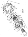
- a constant velocity joint for use, for example, in a vehicle in accordance with the present invention.
- a Rzeppa type constant velocity joint is shown and discussed.
- the illustrated constant velocity joint 10 includes an outer race 12, an inner race 14, a plurality of balls 16, a cage 18, and a splined shaft 20.
- the outer race 12 is adapted to be connected to a shaft (not shown) that can be connected, for example, to an axle (not shown) of the vehicle. Fasteners, such as bolts, can be used to connect the outer race 12 to a flange disposed on the end of the shaft, for example.
- the outer race 12 has a central aperture or opening 22 formed therein.
- a plurality of grooves 24 is formed on an inner wall surrounding the opening 22 of the outer race 12. In the embodiment shown, six of such grooves 24 are formed. However, it will be appreciated that a greater or lesser number of such grooves 24 can be used as desired without departing from the scope and spirit of the invention.
- Each of the illustrated grooves 24 has a generally semi-circular cross sectional shape, although such is not required.
- the inner race 14 has a central splined opening 26 formed therethrough.
- the splined opening 26 is adapted to receive the splined shaft 20 and facilitates concurrent rotation of the splined shaft 20 and the inner race 14, as is well known in the art.
- the inner race 14 has an outer surface 28 that is generally cylindrical in shape, but is slightly curved along an axis of rotation R from one axial end of the inner race 14 to the other.
- a plurality of radially inwardly extending grooves 30 are formed in the outer surface 28 of the inner race 14. In the embodiment shown, six of such grooves 30 are formed.
- the number of grooves 30 formed in the outer surface 28 of the inner race 14 is preferably equal the number of grooves 24 formed in the outer race 12. However, it will be appreciated that a greater or lesser number of such grooves 30 can be used as desired without departing from the scope and spirit of the invention.
- the illustrated grooves 30 are formed to have altematingly inclined facing surfaces relative to the axis of rotation R. Each of the grooves 24 of the outer race 12 is associated with a corresponding groove 30 of the inner race 14.
- One or more webs or raised surfaces 32 are formed on portions of the outer surface 28 of the inner race 14.
- each of the webs 32 is located between adjacent pairs of the grooves 30 formed in the inner race 14.
- Each of the illustrated webs 32 includes a raised surface that extends radially outwardly from the outer surface 28 of the inner race 14 into engagement with an inner surface of the cage 18.
- Each of the illustrated webs 32 extends generally parallel to the axis of rotation R substantially along the entire axial length of the inner race 14, although such is not required.
- each of the webs 32 has a height of approximately 0.50 mm as measured from the outer surface 28 and a width of approximately 3.80 mm as measured in a direction substantially perpendicular to the axis of rotation R.
- the webs 32 may be formed having dimensions that are smaller or larger as desired without departing from the scope and spirit of the invention. It will also be appreciated that similar web or webs could alternatively be formed on an inner surface of the cage 18 and extend radially inwardly therefrom into engagement with the outer surface of the inner race 14 without departing from the scope and spirit of the invention.
- the cage 18 has a central aperture 33 and an outer surface 34 that may be shaped in accordance with the shape of the inner wall of the outer race 12.
- the central aperture 33 is adapted to receive the inner race 14 therein.
- An annular array of apertures 36 is formed through the cage 18.
- the apertures 36 are adapted to respectively receive the balls 16 therein and position the balls 16 in the grooves 24 of the outer race 12 and the grooves 30 of the inner race 14 when the constant velocity joint 10 is assembled.
- One or more webs or raised surfaces 38 are formed on portions of the outer surface 34 of the cage 18.
- each of the webs 38 is located between adjacent pairs of the apertures 36 formed through the cage 18.
- Each of the illustrated webs 38 includes a raised surface that extends radially outwardly from the outer surface 34 of the cage 18 into engagement with the inner surface of the outer race 12.
- Each of the illustrated webs 38 extends substantially parallel to the axis of rotation R substantially along the entire axial length of the cage 18, although such is not required.
- each of the webs 38 has a height of approximately 0.50 mm as measured from the outer surface 34 and a width of approximately 3.80 mm as measured in a direction substantially perpendicular to the axis of rotation R.
- similar web or webs 38 may be formed having dimensions that are smaller or larger as desired can be used without departing from the scope and spirit of the invention. It will also be appreciated that similar web or webs could alternatively be formed on the inner surface of the outer race 12 and extend radially inwardly therefrom into engagement with the outer surface 34 of the cage 18 without departing from the scope and spirit of the invention.
- the constant velocity join 10 is a fixed center joint, wherein relative axial movement between the outer race 12 and the inner race 14 is prevented.
- the webs 32 are provided on the outer surface 28 of the inner race 14 or the inner surface of the cage 18.
- the surface area of the engaging portions of the webs 32 of the inner race 14 and the inner surface of the cage 18 is relatively small.
- the constant velocity joint 10 is rotated at relatively high speeds (i.e., 1500 rpm or higher), articulated at relatively large angles (i.e., 10° to 12° or higher), or otherwise subjected to relatively large axial loads during use, a significantly lesser amount of friction occurs between the engaging portions of the webs 32 of the inner race 14 and the inner surface of the cage 18.
- the webs 38 are provided on the outer surface 34 of the cage 18 or the inner surface of the outer race 12.
- the surface area of the engaging portions of the webs 38 of the cage 18 and the inner surface of the outer race 12 is relatively small.
- the constant velocity joint 10 is rotated at relatively high speeds (i.e., 1500 rpm or higher), articulated at relatively large angles (i.e., 10° to 12° or higher), or otherwise subjected to relatively large axial loads during use, a significantly lesser amount of friction occurs between the engaging portions of the webs 32 of the cage 18 and the inner surface of the outer race 12.
- the surface area defined by the webs 32 of the inner race 14 is preferably substantially smaller than the surface area defined by the outer surface 28 of the inner race 14 that would otherwise engage the inner surface of the cage 18.
- the surface area defined by the webs 38 of the cage 18 is preferably substantially smaller than the surface area defined by the outer surface 34 of the cage 18 that would otherwise engage the inner surface of the outer race 12.
- the term “substantially smaller” means that the surface area defined by the webs 32 is less than one-half of the surface area defined by the outer surface 28 of the inner race 14 that would otherwise engage the inner surface of the cage 18, and that the surface area defined by the webs 38 of the cage 18 is less than one-half of the surface area defined by the outer surface 34 of the cage 18 that would otherwise engage the inner surface of the outer race 12.
- Fig. 4 illustrates a second embodiment of an inner race 50 for the Rzeppa type constant velocity joint 10 in accordance with the present invention.
- the second embodiment of the inner race 50 is, in large measure, similar to the first embodiment illustrated in Fig. 2, and like reference numbers are used to indicate similar components.
- one or more webs or raised surfaces 52 are formed on portions of the outer surface 28 of the inner race 50.
- each of the webs 52 is located between adjacent pairs of the grooves 30 formed in the inner race 14.
- Each of the illustrated webs 52 includes a raised surface that extends radially outwardly from the outer surface 28 of the inner race 14.
- Each of the illustrated webs 52 extends generally circumferentially relative to the axis of rotation R substantially along the entire length between the adjacent grooves 30 of the inner race 14, although such is not required. It will be appreciated that the webs 32 may be formed having dimensions that are smaller or larger as desired without departing from the scope and spirit of the invention. It will also be appreciated that similar web or webs could alternatively be formed on an inner surface of the cage 18 and extend radially inwardly therefrom without departing from the scope and spirit of the invention.
- Fig. 5 illustrates a second embodiment of a cage 60 for the Rzeppa type constant velocity joint 10 in accordance with the present invention.
- the second embodiment of the cage 60 is, in large measure, similar to the first embodiment illustrated in Fig. 3, and like reference numbers are used to indicate similar components.
- one or more webs or raised surfaces 62 are formed on portions of the outer surface 34 of the cage 18.
- each of the webs 62 is located between adjacent pairs of the apertures 36-formed through the cage 18.
- Each of the illustrated webs 62 includes a raised surface that extends radially outwardly from the outer surface 34 of the cage 18.
- Each of the illustrated webs 62 extends generally circumferentially relative to the axis of rotation R substantially along the entire length between the adjacent apertures 36 of the cage 18, although such is not required. It will be appreciated that similar web or webs 62 may be formed having dimensions that are smaller or larger as desired can be used without departing from the scope and spirit of the invention. It will also be appreciated that similar web or webs could alternatively be formed on the inner surface of the outer race 12 and extend radially inwardly therefrom without departing from the scope and spirit of the invention.
- Fig. 6 illustrates a third embodiment of an inner race 70 for the Rzeppa type constant velocity joint 10 in accordance with the present invention.
- the third embodiment of the inner race 70 is, in large measure, similar to the first embodiment illustrated in Fig. 2, and like reference numbers are used to indicate similar components.
- one or more webs or raised surfaces 72 are formed on portions of the outer surface 28 of the inner race 50.
- two of such webs 72 extend circumferentially relative to the axis of rotation R and are located adjacent to the axial ends of the cage 70.
- the webs 72 may be formed having dimensions that are smaller or larger as desired without departing from the scope and spirit of the invention.
- similar web or webs could alternatively be formed on an inner surface of the cage 18 and extend radially inwardly therefrom without departing from the scope and spirit of the invention.
- Fig. 7 illustrates a fourth embodiment of an inner race 80 for the Rzeppa type constant velocity joint 10 in accordance with the present invention.
- the fourth embodiment of the inner race 80 is, in large measure, similar to the first embodiment illustrated in Fig. 2, and like reference numbers are used to indicate similar components.
- one or more webs or raised surfaces 82 are formed on portions of the outer surface 28 of the inner race 50.
- the webs 82 extend helically or diagonally relative to the axis of rotation R. It will be appreciated that the webs 82 may be formed having dimensions that are smaller or larger as desired without departing from the scope and spirit of the invention. It will also be appreciated that similar web or webs could alternatively be formed on an inner surface of the cage 18 and extend radially inwardly therefrom without departing from the scope and spirit of the invention.
Landscapes
- Engineering & Computer Science (AREA)
- General Engineering & Computer Science (AREA)
- Mechanical Engineering (AREA)
- Rolling Contact Bearings (AREA)
- Shafts, Cranks, Connecting Bars, And Related Bearings (AREA)
- Motor Power Transmission Devices (AREA)
Applications Claiming Priority (2)
| Application Number | Priority Date | Filing Date | Title |
|---|---|---|---|
| US705258 | 2003-11-10 | ||
| US10/705,258 US20050101391A1 (en) | 2003-11-10 | 2003-11-10 | Constant velocity joint having friction reducing web locators |
Publications (1)
| Publication Number | Publication Date |
|---|---|
| EP1529978A1 true EP1529978A1 (de) | 2005-05-11 |
Family
ID=34435605
Family Applications (1)
| Application Number | Title | Priority Date | Filing Date |
|---|---|---|---|
| EP04256930A Withdrawn EP1529978A1 (de) | 2003-11-10 | 2004-11-09 | Gleichlaufdrehgelenk mit einem reibungsvermindernden Positionierungsfedermusterprofil |
Country Status (6)
| Country | Link |
|---|---|
| US (1) | US20050101391A1 (de) |
| EP (1) | EP1529978A1 (de) |
| KR (1) | KR20050045834A (de) |
| CN (1) | CN1624353A (de) |
| AU (1) | AU2004229008A1 (de) |
| BR (1) | BRPI0404956A (de) |
Cited By (6)
| Publication number | Priority date | Publication date | Assignee | Title |
|---|---|---|---|---|
| DE102005023045B4 (de) * | 2005-05-13 | 2009-12-03 | Gkn Driveline Deutschland Gmbh | Gelenk mit höher belastbarem Gelenkinnenteil |
| WO2010022760A1 (en) * | 2008-08-28 | 2010-03-04 | Gkn Driveline International Gmbh | Inner joint part of constant velocity universal joint |
| WO2010022761A1 (en) * | 2008-08-28 | 2010-03-04 | Gkn Driveline International Gmbh | Inner joint part of constant velocity universal joint |
| DE102010010487A1 (de) * | 2010-03-06 | 2011-09-08 | Neumayer Tekfor Holding Gmbh | Käfig für Kugelgelenk und Kugelgelenk |
| CN103216539A (zh) * | 2012-06-20 | 2013-07-24 | 襄阳宇清传动科技有限公司 | 输油管螺杆泵用球笼联轴器 |
| EP2592293A4 (de) * | 2010-07-07 | 2018-04-18 | JTEKT Corporation | Gleichlauf-kugelgelenk |
Families Citing this family (4)
| Publication number | Priority date | Publication date | Assignee | Title |
|---|---|---|---|---|
| CN100365303C (zh) * | 2006-03-27 | 2008-01-30 | 曹江浪 | 鼓形销式球铰万向联轴器 |
| US8070611B2 (en) * | 2009-05-13 | 2011-12-06 | Gkn Driveline North America, Inc. | Plunging cross-track constant velocity joint |
| DE102017210135B4 (de) * | 2017-06-16 | 2021-02-11 | Volkswagen Aktiengesellschaft | Kugelkäfig für VL- und CG-Gelenke |
| KR20250102555A (ko) * | 2023-12-28 | 2025-07-07 | 현대위아 주식회사 | 볼 타입 등속조인트 |
Citations (5)
| Publication number | Priority date | Publication date | Assignee | Title |
|---|---|---|---|---|
| GB956894A (en) * | 1962-04-18 | 1964-04-29 | Daimler Benz Ag | Improvements in axially slidable shaft and like joints or couplings |
| JPS53131350A (en) * | 1977-04-21 | 1978-11-16 | Honda Motor Co Ltd | Cage of barfield type uniform-speed joint and its manufacturing method |
| JPS55166527A (en) * | 1979-06-09 | 1980-12-25 | Toyota Motor Corp | Constant speed ball joint |
| DE19648537C1 (de) * | 1996-11-25 | 1998-07-30 | Loehr & Bromkamp Gmbh | Gleichlaufgelenkwelle |
| DE19958719A1 (de) * | 1999-09-14 | 2001-03-15 | Iprotec Masch & Edelstahlprod | Kugelkäfig |
Family Cites Families (15)
| Publication number | Priority date | Publication date | Assignee | Title |
|---|---|---|---|---|
| US1071693A (en) * | 1909-06-11 | 1913-09-02 | Hess Bright Mfg Co | Antifriction-bearing. |
| US2047660A (en) * | 1935-06-25 | 1936-07-14 | Milton B Anderson | Universal joint |
| US3400557A (en) * | 1966-08-22 | 1968-09-10 | Gen Motors Corp | Fixed center constant velocity universal joint |
| DE2430027C2 (de) * | 1974-06-22 | 1976-01-08 | Loehr & Bromkamp Gmbh, 6050 Offenbach | Gleichlaufdrehgelenk |
| DE2636085C2 (de) * | 1976-08-11 | 1978-09-21 | Loehr & Bromkamp Gmbh, 6050 Offenbach | Gleichlaufdrehgelenk |
| ES2014055A6 (es) * | 1988-03-17 | 1990-06-16 | Loehr & Bromkamp Gmbh | Articulacion desplazable sincronizada. |
| DE4042391C2 (de) * | 1990-10-08 | 1995-07-06 | Gkn Automotive Ag | Gleichlaufdrehgelenk |
| CA2072444A1 (en) * | 1991-08-27 | 1993-02-28 | James W. Warnke | Cross groove constant velocity joint having fixed center |
| US5433668A (en) * | 1992-04-03 | 1995-07-18 | Gkn Automotive Ag | Constant velocity fixed joint with supporting inserts |
| US5348512A (en) * | 1992-11-12 | 1994-09-20 | Ina Bearing Company, Inc. | Friction reduced constant velocity universal joint |
| JPH09158956A (ja) * | 1995-12-05 | 1997-06-17 | Toyota Motor Corp | シャフト組立体 |
| FR2744502B1 (fr) * | 1996-02-01 | 1998-04-24 | Gkn Glaenzer Spicer | Joint de transmission homocinetique a billes |
| US5725431A (en) * | 1996-09-26 | 1998-03-10 | Dana Corporation | Thrust washer for universal joint having preloading thrust surfaces |
| JP3909992B2 (ja) * | 1999-11-30 | 2007-04-25 | Ntn株式会社 | 固定式等速自在継手のケージおよびその製造方法並びに固定式等速自在継手 |
| US6461244B2 (en) * | 2000-02-18 | 2002-10-08 | Gkn Automotive, Inc. | Constant velocity fixed joint with improved cage assembly |
-
2003
- 2003-11-10 US US10/705,258 patent/US20050101391A1/en not_active Abandoned
-
2004
- 2004-11-05 KR KR1020040089851A patent/KR20050045834A/ko not_active Withdrawn
- 2004-11-09 AU AU2004229008A patent/AU2004229008A1/en not_active Abandoned
- 2004-11-09 EP EP04256930A patent/EP1529978A1/de not_active Withdrawn
- 2004-11-10 BR BR0404956-0A patent/BRPI0404956A/pt not_active Application Discontinuation
- 2004-11-10 CN CNA200410082051XA patent/CN1624353A/zh active Pending
Patent Citations (5)
| Publication number | Priority date | Publication date | Assignee | Title |
|---|---|---|---|---|
| GB956894A (en) * | 1962-04-18 | 1964-04-29 | Daimler Benz Ag | Improvements in axially slidable shaft and like joints or couplings |
| JPS53131350A (en) * | 1977-04-21 | 1978-11-16 | Honda Motor Co Ltd | Cage of barfield type uniform-speed joint and its manufacturing method |
| JPS55166527A (en) * | 1979-06-09 | 1980-12-25 | Toyota Motor Corp | Constant speed ball joint |
| DE19648537C1 (de) * | 1996-11-25 | 1998-07-30 | Loehr & Bromkamp Gmbh | Gleichlaufgelenkwelle |
| DE19958719A1 (de) * | 1999-09-14 | 2001-03-15 | Iprotec Masch & Edelstahlprod | Kugelkäfig |
Non-Patent Citations (2)
| Title |
|---|
| PATENT ABSTRACTS OF JAPAN vol. 003, no. 008 (M - 046) 25 January 1979 (1979-01-25) * |
| PATENT ABSTRACTS OF JAPAN vol. 005, no. 043 (M - 060) 23 March 1981 (1981-03-23) * |
Cited By (10)
| Publication number | Priority date | Publication date | Assignee | Title |
|---|---|---|---|---|
| DE102005023045B4 (de) * | 2005-05-13 | 2009-12-03 | Gkn Driveline Deutschland Gmbh | Gelenk mit höher belastbarem Gelenkinnenteil |
| WO2010022760A1 (en) * | 2008-08-28 | 2010-03-04 | Gkn Driveline International Gmbh | Inner joint part of constant velocity universal joint |
| WO2010022761A1 (en) * | 2008-08-28 | 2010-03-04 | Gkn Driveline International Gmbh | Inner joint part of constant velocity universal joint |
| DE102008044657B4 (de) | 2008-08-28 | 2023-01-26 | Gkn Driveline International Gmbh | Gelenkinnenteil für ein Gleichlaufdrehgelenk |
| DE102010010487A1 (de) * | 2010-03-06 | 2011-09-08 | Neumayer Tekfor Holding Gmbh | Käfig für Kugelgelenk und Kugelgelenk |
| US8419554B2 (en) | 2010-03-06 | 2013-04-16 | Neumayer Tekfor Holding Gmbh | Cage for ball joint and ball joint |
| DE102010010487B4 (de) | 2010-03-06 | 2022-01-13 | Neumayer Tekfor Engineering Gmbh | Käfig für Kugelgelenk und Kugelgelenk |
| EP2592293A4 (de) * | 2010-07-07 | 2018-04-18 | JTEKT Corporation | Gleichlauf-kugelgelenk |
| CN103216539A (zh) * | 2012-06-20 | 2013-07-24 | 襄阳宇清传动科技有限公司 | 输油管螺杆泵用球笼联轴器 |
| CN103216539B (zh) * | 2012-06-20 | 2015-09-09 | 襄阳宇清传动科技有限公司 | 输油管螺杆泵用球笼联轴器 |
Also Published As
| Publication number | Publication date |
|---|---|
| CN1624353A (zh) | 2005-06-08 |
| BRPI0404956A (pt) | 2005-07-19 |
| KR20050045834A (ko) | 2005-05-17 |
| US20050101391A1 (en) | 2005-05-12 |
| AU2004229008A1 (en) | 2005-05-26 |
Similar Documents
| Publication | Publication Date | Title |
|---|---|---|
| US6736729B2 (en) | Constant velocity joint and method of making same | |
| US7771283B2 (en) | Propshaft with constant velocity joint attachment | |
| US8449399B2 (en) | Joint assembly with centering flange | |
| US7396285B2 (en) | Counter track joint with track turning point | |
| US5647800A (en) | Cross groove constant velocity joint having fixed center | |
| EP1529978A1 (de) | Gleichlaufdrehgelenk mit einem reibungsvermindernden Positionierungsfedermusterprofil | |
| US20050215330A1 (en) | Boot with articulating and plunging convolutes | |
| EP1469217A2 (de) | Präzisionsdichtung für Axiallager | |
| CA1168461A (en) | Coupling | |
| JP5183930B2 (ja) | 固定式等速自在継手 | |
| CN101052817B (zh) | 相对滚道接头形式的恒速接头、驱动轴和机动车辆 | |
| US4036032A (en) | Universal joint | |
| US6872143B2 (en) | Driveshaft with counter-track joint | |
| US4634402A (en) | Universal joint capable of accommodating thrust loads | |
| JP4262863B2 (ja) | 固定型等速自在継手 | |
| US7635307B2 (en) | Propeller shaft | |
| US20250327488A1 (en) | Constant velocity joint provided with grease retainer | |
| US7914382B2 (en) | Dual type constant velocity universal joint | |
| JP2583634Y2 (ja) | 自動車用トリポード型等速ジョイント | |
| US7097565B2 (en) | Fixed-center articulating constant velocity joint | |
| US20050250585A1 (en) | Propeller shaft and method of installing the same | |
| JP2008261390A (ja) | 固定式等速自在継手 | |
| GB2312943A (en) | Constant velocity universal joint | |
| JP2005273820A (ja) | 等速たわみ継手 |
Legal Events
| Date | Code | Title | Description |
|---|---|---|---|
| PUAI | Public reference made under article 153(3) epc to a published international application that has entered the european phase |
Free format text: ORIGINAL CODE: 0009012 |
|
| AK | Designated contracting states |
Kind code of ref document: A1 Designated state(s): AT BE BG CH CY CZ DE DK EE ES FI FR GB GR HU IE IS IT LI LU MC NL PL PT RO SE SI SK TR |
|
| AX | Request for extension of the european patent |
Extension state: AL HR LT LV MK YU |
|
| 17P | Request for examination filed |
Effective date: 20051107 |
|
| AKX | Designation fees paid |
Designated state(s): DE ES GB IT |
|
| STAA | Information on the status of an ep patent application or granted ep patent |
Free format text: STATUS: THE APPLICATION IS DEEMED TO BE WITHDRAWN |
|
| 18D | Application deemed to be withdrawn |
Effective date: 20060425 |