EP1529948A2 - Pre-controlling process of a variable lift fuel pump in an Internal combustion engine - Google Patents
Pre-controlling process of a variable lift fuel pump in an Internal combustion engine Download PDFInfo
- Publication number
- EP1529948A2 EP1529948A2 EP04021981A EP04021981A EP1529948A2 EP 1529948 A2 EP1529948 A2 EP 1529948A2 EP 04021981 A EP04021981 A EP 04021981A EP 04021981 A EP04021981 A EP 04021981A EP 1529948 A2 EP1529948 A2 EP 1529948A2
- Authority
- EP
- European Patent Office
- Prior art keywords
- pressure
- fuel
- fuel pump
- rail
- volume
- Prior art date
- Legal status (The legal status is an assumption and is not a legal conclusion. Google has not performed a legal analysis and makes no representation as to the accuracy of the status listed.)
- Granted
Links
- 239000000446 fuel Substances 0.000 title claims abstract description 261
- 238000000034 method Methods 0.000 title claims abstract description 23
- 238000002485 combustion reaction Methods 0.000 title claims abstract description 11
- 230000008569 process Effects 0.000 title abstract description 3
- 230000008859 change Effects 0.000 claims abstract description 19
- 238000002347 injection Methods 0.000 claims abstract description 18
- 239000007924 injection Substances 0.000 claims abstract description 18
- 238000007906 compression Methods 0.000 claims description 85
- 230000006835 compression Effects 0.000 claims description 78
- 238000000605 extraction Methods 0.000 claims description 10
- 238000006073 displacement reaction Methods 0.000 claims description 6
- 230000000630 rising effect Effects 0.000 claims description 4
- 230000007246 mechanism Effects 0.000 claims description 3
- 230000015572 biosynthetic process Effects 0.000 abstract description 4
- TZCXTZWJZNENPQ-UHFFFAOYSA-L barium sulfate Chemical group [Ba+2].[O-]S([O-])(=O)=O TZCXTZWJZNENPQ-UHFFFAOYSA-L 0.000 description 5
- 239000012071 phase Substances 0.000 description 4
- 238000004364 calculation method Methods 0.000 description 3
- 239000002828 fuel tank Substances 0.000 description 3
- 230000004913 activation Effects 0.000 description 2
- 239000012080 ambient air Substances 0.000 description 2
- 230000008901 benefit Effects 0.000 description 2
- 230000001419 dependent effect Effects 0.000 description 2
- 238000010586 diagram Methods 0.000 description 2
- 238000002474 experimental method Methods 0.000 description 2
- 239000007788 liquid Substances 0.000 description 2
- 230000009467 reduction Effects 0.000 description 2
- SQQCWHCJRWYRLB-UHFFFAOYSA-N 2,3,4,5,6-pentahydroxy-1-[4-[4-[(2,3,4,5,6-pentahydroxy-1-sulfohexyl)amino]phenyl]sulfonylanilino]hexane-1-sulfonic acid Chemical compound C1=CC(NC(C(O)C(O)C(O)C(O)CO)S(O)(=O)=O)=CC=C1S(=O)(=O)C1=CC=C(NC(C(O)C(O)C(O)C(O)CO)S(O)(=O)=O)C=C1 SQQCWHCJRWYRLB-UHFFFAOYSA-N 0.000 description 1
- 229940076664 close up Drugs 0.000 description 1
- 238000012937 correction Methods 0.000 description 1
- 238000013461 design Methods 0.000 description 1
- 238000001514 detection method Methods 0.000 description 1
- 230000000694 effects Effects 0.000 description 1
- 239000012530 fluid Substances 0.000 description 1
- 239000007792 gaseous phase Substances 0.000 description 1
- 239000000203 mixture Substances 0.000 description 1
- 230000001360 synchronised effect Effects 0.000 description 1
- 238000012546 transfer Methods 0.000 description 1
- 230000001960 triggered effect Effects 0.000 description 1
Images
Classifications
-
- F—MECHANICAL ENGINEERING; LIGHTING; HEATING; WEAPONS; BLASTING
- F02—COMBUSTION ENGINES; HOT-GAS OR COMBUSTION-PRODUCT ENGINE PLANTS
- F02D—CONTROLLING COMBUSTION ENGINES
- F02D41/00—Electrical control of supply of combustible mixture or its constituents
- F02D41/30—Controlling fuel injection
- F02D41/38—Controlling fuel injection of the high pressure type
- F02D41/3809—Common rail control systems
- F02D41/3836—Controlling the fuel pressure
- F02D41/3845—Controlling the fuel pressure by controlling the flow into the common rail, e.g. the amount of fuel pumped
-
- F—MECHANICAL ENGINEERING; LIGHTING; HEATING; WEAPONS; BLASTING
- F02—COMBUSTION ENGINES; HOT-GAS OR COMBUSTION-PRODUCT ENGINE PLANTS
- F02M—SUPPLYING COMBUSTION ENGINES IN GENERAL WITH COMBUSTIBLE MIXTURES OR CONSTITUENTS THEREOF
- F02M63/00—Other fuel-injection apparatus having pertinent characteristics not provided for in groups F02M39/00 - F02M57/00 or F02M67/00; Details, component parts, or accessories of fuel-injection apparatus, not provided for in, or of interest apart from, the apparatus of groups F02M39/00 - F02M61/00 or F02M67/00; Combination of fuel pump with other devices, e.g. lubricating oil pump
- F02M63/02—Fuel-injection apparatus having several injectors fed by a common pumping element, or having several pumping elements feeding a common injector; Fuel-injection apparatus having provisions for cutting-out pumps, pumping elements, or injectors; Fuel-injection apparatus having provisions for variably interconnecting pumping elements and injectors alternatively
- F02M63/0225—Fuel-injection apparatus having a common rail feeding several injectors ; Means for varying pressure in common rails; Pumps feeding common rails
- F02M63/0275—Arrangement of common rails
- F02M63/028—Returnless common rail system
-
- F—MECHANICAL ENGINEERING; LIGHTING; HEATING; WEAPONS; BLASTING
- F02—COMBUSTION ENGINES; HOT-GAS OR COMBUSTION-PRODUCT ENGINE PLANTS
- F02D—CONTROLLING COMBUSTION ENGINES
- F02D41/00—Electrical control of supply of combustible mixture or its constituents
- F02D41/02—Circuit arrangements for generating control signals
- F02D41/14—Introducing closed-loop corrections
- F02D41/1401—Introducing closed-loop corrections characterised by the control or regulation method
- F02D2041/141—Introducing closed-loop corrections characterised by the control or regulation method using a feed-forward control element
-
- F—MECHANICAL ENGINEERING; LIGHTING; HEATING; WEAPONS; BLASTING
- F02—COMBUSTION ENGINES; HOT-GAS OR COMBUSTION-PRODUCT ENGINE PLANTS
- F02D—CONTROLLING COMBUSTION ENGINES
- F02D2250/00—Engine control related to specific problems or objectives
- F02D2250/02—Fuel evaporation in fuel rails, e.g. in common rails
Definitions
- the invention relates to a method for piloting a stroke piston fuel pump of a Internal combustion engine, in particular of a motor vehicle, wherein the internal combustion engine a High-pressure rail and associated injection valves, according to the preamble of Claim 1.
- a bulkhead of a reciprocating piston fuel pump for a fuel supply of a Internal combustion engine sets an amount of fuel that is in the reciprocating piston fuel pump compressed and pushed into a high-pressure rail.
- a control algorithm implements the opening and closing times or angles of the quantity control station the pump is calculated. These opening and closing times are in shape an electrical signal output to the bulkhead.
- the invention is based on the object with regard to a method of the abovementioned type with regard to activation the Mengenstelltechniks the Hub piston fuel pump to achieve a high Accuracy in providing the fuel injection amount and the fuel injection pressure to improve in the high pressure rail and to make it more robust against disturbances.
- the stroke-piston fuel pump from the input values volume of fuel removal vevphh from the high pressure rail through the fuel injection valves per stroke, the stroke-piston fuel pump, fuel volume vdaavst which a change to the setpoint pressure .DELTA.p _ rail to the high-pressure rail per stroke, the stroke-piston fuel pump vkdavst , which requires the piston of the reciprocating piston fuel pump for compression of the fuel from low pressure to pressure in the high pressure rail per stroke of the reciprocating piston fuel pump, as well as volume loss vvlfghdp by not optimal delivery due to Damfblasen realise in the fuel per stroke of Hub Piston Fuel Pump Closing and opening times for a bulkhead of the reciprocating piston fuel pump are determined.
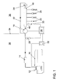
- Fig. 1 illustrates a non-return fuel system with a fuel tank 10, a electric fuel pump 12, a fuel filter 14, a reciprocating piston fuel pump or high-pressure pump (HDP) 16 with quantity control station, a high-pressure rail 18, a plurality of high-pressure injection valves (HDEV) 20, a return line 22, a pressure relief valve (DBV) 24, an engine control unit (ECU) 26, a low pressure sensor 28, a high pressure sensor 30 and a power output stage 32 for driving the fuel pump 12.
- Line 34 separates the fuel system into a high pressure side 36 and a low pressure side 36.
- the electric fuel pump (EKP) 12 serves as a feed pump for the Hub Piston Fuel Pump (HDP) 16.
- the Hub Piston Fuel Pump (HDP) 16 provides the Fuel pressure in the distribution bar or high-pressure rail 18 a.
- the high pressure injectors 20 are supplied from the high-pressure rail 20 with fuel.
- About the return line 22nd fuel flows back when the pressure in the high-pressure rail is a safety-critical one Exceeds limit. This can only occur in the event of a fault.
- a leakage line, not shown the Hub Piston Fuel Pump (HDP) 16 discharges fuel contained in the Hub Piston Fuel Pump (HDP) 16 escapes between piston and cylinder. This amount is however relatively small.
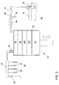
- the stroke piston fuel pump 16 includes, as shown in FIG. 2, a piston 40 in a cylinder 42 which performs a lifting movement. This lifting movement is divided into a downward and upward movement. In the downward movement is a displacement with fuel from the fuel tank 10 of the low pressure system 38 filled with fuel. In the upward movement the compression of the fuel takes place.
- a quantity control station in the form of a Rate control valve 44 disconnects during a predetermined portion of the upstroke Compression space from the supply side or low pressure side 38. During that Section of the upward movement of the piston 40, which is used to compress the fuel is to be used, the bulkhead 44 separates the connection between engine capacity the stroke piston fuel pump 16 and supply line 46.
- the quantity control 44 opens the connection between the displacement the stroke-piston fuel pump 16 and the supply line 46. A closing interval is created, which lies in the compression stroke of the stroke piston fuel pump 16.
- the position of the interval in the compression stroke is in principle freely selectable. Usually will either the closing or the opening time to one of the dead points of the movement of the piston 40 is placed. With both concepts it is possible the effective compression stroke adjust.
- the displacement is with the high pressure rail 18 of the high pressure system 36 via a check valve 48 is connected. As soon as the pressure in the displacement of the Hub piston fuel pump 16 is greater than the pressure in the high-pressure rail 18, the flows compressed fuel from the displacement of the stroke piston fuel pump 16 in the High Pressure Rail 18.
- the engine controller 26 ( Figure 1) provides the switching pulse to the flow control valve (44) of the quantity control station. The duration of this switching pulse sets Considering the piston speed and piston position fixed the effective stroke.
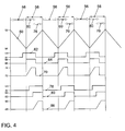
- Fig. 4 illustrates the control of the quantity control station 44 with the two different concepts.
- a graph 50 illustrates the movement of the piston 40 between a top dead center 52 and a bottom dead center 54, wherein a filling 56 and a compression 58 cyclically alternate.
- graph 62 shows a drive signal for the quantity control valve 44 between 0V and 12V, a graph 64 a state of the quantity control valve 44 between "open” 66, and “closed” 68 and a graph 70 a pressure in the compression chamber, the stroke-piston fuel pump 16 between a low pressure p low-pressure 72 in the low pressure system 38 and a high pressure p HD-rail 74 in the high-pressure system 36 or
- graph 78 shows a drive signal for the mass control valve 44 between 0V and 12V
- a graph 80 indicates a state of the mass control valve 44 between "open” 82 and “closed” 84 and a graph 86 a pressure in the compression chamber
- the stroke-piston fuel pump 16 between a low pressure p low-pressure 88 in the low pressure system 38 and a high pressure p HD-rail 90 in the high-pressure system 36 or high-pressure rail 18th
- the closing interval 60 or 76 of the quantity-adjusting mechanism 44 lies between the bottom dead center 54 and the top dead center 52 of the piston 40 of the reciprocating piston fuel pump 16 relative to a piston 40 moving upward in the cylinder 42. In principle, it does not matter if the closing interval immediately after passing through the bottom dead center 54 begins (concept I, arrow 60) or ends with reaching the top dead center 52 (concept II, arrow 76). Both concepts lead to pressure build-up. For energetic reasons, however, the second concept (arrow 76) is preferable.
- the compression process 60 or 76 is triggered by closing the quantity control station 44 with upwardly moving piston 40. The volume of fuel in the compression space at this moment is at approximately low pressure level. By the upward movement of the piston 40, the pressure increases.
- the check valve 48 opens and the fuel flows out of the compression space of the reciprocating piston fuel pump 16 into the high-pressure rail 18. Dies takes place as long as the pressure in the compression chamber above the pressure p HD rail is maintained in the high-pressure rail 18.
- the effective compression stroke is ended by opening the quantity-adjusting mechanism 44 or as soon as the piston 40 reaches its top dead center 52. Depending on the pump design and concept, a residual volume at the end of the compression process 58 may remain in the compression space of the reciprocating piston fuel pump 16.
- the fuel for example petrol
- changes its volume under pressure. This volume change results ⁇ V V 0 * ⁇ p * ⁇
- V 0 is an initial volume [mm 3]
- ⁇ p a change in pressure [bar]
- .DELTA.V a change in volume [mm 3].
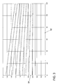
- the one compressibility number ⁇ [1 / bar] for the fluid to be compressed results, as a function of temperature and pressure, from a family of curves according to FIG. 3.
- FIG. 3 shows a pressure in [bar] and on a vertical axis 92 on a horizontal axis 92 Axis 94 the compressibility in [E-4 / bar].
- the curves correspond from top to bottom to a temperature of 413K, 393K, 373K, 353K, 333K, 313K, 293K, 273K, 253K and 233K.
- the density of the fuel for the respective operating point is first calculated.
- the fuel flows through first the lift-piston fuel pump 16, the fuel line and then the high-pressure rail 18. There is a heat transfer due to the contact of the fuel with the inner surfaces of the fuel-carrying components instead.
- the source of heat is the engine block or the ambient air in the engine compartment as well as the compression work in the reciprocating piston fuel pump 16. These heat inputs bear the following names t emotr , t eulr and t krailnp .
- the fuel flows into the compression space via the open quantity control 44 at the temperature t flvrhdp . There, the fuel is compressed and flows through the check valve 48 in the high-pressure rail 18. By this thermodynamic process takes place a temperature entry t krailnp in the fuel.
- the dependencies of t emotr , t eulr and t krailnp are determined empirically and stored in curves and maps .
- the dynamic behavior of the temperature t krail in the high-pressure rail 18 is detected.
- the time behavior of the filter is determined as a function of the fuel mass flow Q fuel ) and of the difference between t mot and t krailnp .
- the precontrol of the stroke piston fuel pump 16 is based on the calculation the stroke volume of the piston 40, which is used for the compression of the fuel shall be.
- This stroke volume is defined by closing and opening times the quantity control station 44, taking into account the pump geometry.
- the to be compressed Fuel volume results from the requirements of the engine controller 26 in terms Target fuel pressure in the high-pressure rail 18 and fuel quantity and the current Operating parameters, such as temperature and actual pressures.
- Ap soll_rail is defined as follows: ⁇ p soll_rail> 0 meant that the nominal pressure gradient is positive and Ap soll_rail ⁇ 0 meant the nominal pressure gradient däß negative.
- kmeshdp, tflvrhdp, nmot and p low pressure maps are addressed, which are empirically determined in the experiment.
- the delta crank angle dwms ⁇ s ⁇ g refers to that part of the rising edge of the drive cam for the reciprocating piston fuel pump that is conceptually used for the compression interval.
Landscapes
- Engineering & Computer Science (AREA)
- Chemical & Material Sciences (AREA)
- Combustion & Propulsion (AREA)
- Mechanical Engineering (AREA)
- General Engineering & Computer Science (AREA)
- Fuel-Injection Apparatus (AREA)
- Electrical Control Of Air Or Fuel Supplied To Internal-Combustion Engine (AREA)
Abstract
Description
Die Erfindung betrifft ein Verfahren zum Vorsteuern einer Hub-Kolben-Kraftstoffpumpe einer Brennkraftmaschine, insbesondere eines Kraftfahrzeugs, wobei die Brennkraftmaschine ein Hochdruckrail und damit verbundene Einspritzventile aufweist, gemäß dem Oberbegriff des Anspruchs 1.The invention relates to a method for piloting a stroke piston fuel pump of a Internal combustion engine, in particular of a motor vehicle, wherein the internal combustion engine a High-pressure rail and associated injection valves, according to the preamble of Claim 1.
Ein Mengenstellwerk einer Hub-Kolben-Kraftstoffpumpe für eine Kraftstoffversorgung einer Brennkraftmaschine legt eine Kraftstoffmenge fest, die in der Hub-Kolben-Kraftstoffpumpe komprimiert und in ein Hochdruckrail geschoben wird. In einem Motorsteuergerät ist ein Regelalgorithmus implementiert, der die Öffnungs- und Schließzeiten bzw. -winkel des Mengenstellwerkes der Pumpe berechnet. Diese Öffnungs- und Schließzeiten werden in Form eines elektrischen Signals an das Mengenstellwerk ausgegeben. Für eine abgas- und verbrauchsoptimale Gemischbildung in einem Brennraum der Brennkraftmaschine muß der Kraftstoffdruck und die zur Einspritzung zur Verfügung stehende Kraftstoffmenge im Hochdruckrail so genau wie möglich bereitgestellt werden.A bulkhead of a reciprocating piston fuel pump for a fuel supply of a Internal combustion engine sets an amount of fuel that is in the reciprocating piston fuel pump compressed and pushed into a high-pressure rail. In an engine control unit is a control algorithm implements the opening and closing times or angles of the quantity control station the pump is calculated. These opening and closing times are in shape an electrical signal output to the bulkhead. For an exhaust and consumption-optimal Mixture formation in a combustion chamber of the internal combustion engine must the Fuel pressure and the amount of fuel available for injection in High-pressure rail to be provided as accurately as possible.
Bei einem bekannten Algorithmus für die Ansteuerung des Mengenstellwerkes sind eine Vorsteuerung und ein Regler vorgesehen. In der Vorsteuerung wird die Zeitdauer für die Ansteuerung mit eingeschränkter Genauigkeit ermittelt. Eingangssignale der Vorsteuerung sind die Sollwerte für Kraftstoffdruck und -menge. Auf Basis dieser Sollwerte werden Kennfelder adressiert, in denen ein Ansteuerwinkel abgelegt ist. Diese Kennfelder bilden nicht die physikalischen Gegebenheiten in der Hub-Kolben-Kraftstoffpumpe nach, sondern sind empirisch an exemplarisch ausgewählten Pumpen ermittelt. Durch die Verwendung eines Reglers besteht die Möglichkeit, die in der Vorsteuerung ermittelte Ansteuerdauer des Mengenstellwerkes zu korrigieren. Der Regler arbeitet auf Basis einer Istdruck-Erfassung mit einem Sensor im Hochdruckrail. Dieser Regler ist als PI-Regler ausgelegt. Diese Korrektur ist notwendig, da von den Vorsteuerkennfeldern folgende Zusammenhänge nicht berücksichtigt werden können:
- Die Toleranzlagenstreuung der Pumpe in der Serie.
- Fehler in den Vorsteuerkennfeldern.
- Physikalische Abhängigkeiten, wie beispielsweise Temperaturabhängigkeiten.
- Tolerance distribution of the pump in the series.
- Error in the pilot control maps.
- Physical dependencies, such as temperature dependencies.
Je genauer die Vorsteuerkennfelder den realen Bedingungen entsprechen, desto kleiner fallen die Eingriffe des Reglers aus.The more accurately the pilot control maps correspond to the real conditions, the smaller fall out the interventions of the controller.
Der Erfindung liegt die Aufgabe zugrunde, ein Verfahren der obengenannten Art bzgl. Ansteuerung des Mengenstellwerks der Hub-Kolben-Kraftstoffpumpe zum Erzielen einer hohen Genauigkeit bzgl. der Bereitstellung der Kraftstoffeinspritzmenge und des Kraftstoffeinspritzdruckes im Hochdruckrail zu verbessern und gegen Störungen robuster zu machen.The invention is based on the object with regard to a method of the abovementioned type with regard to activation the Mengenstellwerks the Hub piston fuel pump to achieve a high Accuracy in providing the fuel injection amount and the fuel injection pressure to improve in the high pressure rail and to make it more robust against disturbances.
Diese Aufgabe wird erfindungsgemäß durch ein Verfahren der o.g. Art mit den in Anspruch 1 gekennzeichneten Merkmalen gelöst. Vorteilhafte Ausgestaltungen der Erfindung sind in den abhängigen Ansprüchen angegeben.This object is achieved by a method of o.g. Type with the in claim 1 characterized features solved. Advantageous embodiments of the invention are in the specified dependent claims.
Dazu ist es erfindungsgemäß vorgesehen, daß aus den Eingangswerten Kraftstoffvolumenentnahme vevphh aus dem Hochdruckrail durch die Einspritzventile pro Hub der Hub-Kolben-Kraftstoffpumpe, Kraftstoffvolumen vdaavst, welches für eine Änderung des Solldruckes Δp soll _ rail im Hochdruckrail pro Hub der Hub-Kolben-Kraftstoffpumpe benötigt wird, Hubvolumen vkdavst , welches der Kolben der Hub-Kolben-Kraftstoffpumpe zur Verdichtung des Kraftstoffes von Niederdruck auf Druck im Hochdruckrail pro Hub der Hub-Kolben-Kraftstoffpumpe benötigt, sowie Volumenverlust vvlfghdp durch nicht optimalen Liefergrad aufgrund von Damfblasenbildung im Kraftstoff pro Hub der Hub-Kolben-Kraftstoffpumpe Schließ- und Öffnungszeitpunkte für ein Mengenstellwerk der Hub-Kolben-Kraftstoffpumpe bestimmt werden.For this purpose the invention it is provided that from the input values volume of fuel removal vevphh from the high pressure rail through the fuel injection valves per stroke, the stroke-piston fuel pump, fuel volume vdaavst which a change to the setpoint pressure .DELTA.p _ rail to the high-pressure rail per stroke, the stroke-piston fuel pump vkdavst , which requires the piston of the reciprocating piston fuel pump for compression of the fuel from low pressure to pressure in the high pressure rail per stroke of the reciprocating piston fuel pump, as well as volume loss vvlfghdp by not optimal delivery due to Damfblasenbildung in the fuel per stroke of Hub Piston Fuel Pump Closing and opening times for a bulkhead of the reciprocating piston fuel pump are determined.
Dies hat den Vorteil, daß eine höhere Genauigkeit bei geringerem Applikationsaufwand und besserer Diagnosefähigkeit erzielt wird, wobei unterschiedliche Pumpenkonzepte realisierbar sind.This has the advantage that a higher accuracy with less application costs and better diagnostic capability is achieved, with different pump concepts feasible are.
Weitere Merkmale, Vorteile und vorteilhafte Ausgestaltungen der Erfindung ergeben sich aus den abhängigen Ansprüchen, sowie aus der nachstehenden Beschreibung der Erfindung anhand der beigefügten Zeichnungen. Diese zeigen in
- Fig. 1
- ein schematisches Schaltbild eines bekannten, rücklauffreien Kraftstoffsystems,
- Fig. 2
- ein schematisches Schaltbild der Funktionsweise einer Hub-Kolben-Kraftstoffpumpe zur Veranschaulichung des erfindungsgemäßen Verfahrens und
- Fig. 3
- ein Kennfeld für die Kompressibilität des Kraftstoffs in Abhängigkeit von Druck und Temperatur.
- Fig. 4
- eine schematische Darstellung der Ansteuerung eines Mengenstellwerkes einer Hub-Kolben-Kraftstoffpumpe,
- Fig. 1
- a schematic diagram of a known, non-return fuel system,
- Fig. 2
- a schematic diagram of the operation of a reciprocating-piston fuel pump to illustrate the method according to the invention and
- Fig. 3
- a map for the compressibility of the fuel as a function of pressure and temperature.
- Fig. 4
- a schematic representation of the control of a quantity control station of a reciprocating piston fuel pump,
Fig. 1 veranschaulicht ein rücklauffreies Kraftstoffsystem mit einem Kraftstofftank 10, einer
elektrischen Kraftstoffpumpe 12, einem Kraftstoff-Filter 14, einer Hub-Kolben-Kraftstoffpumpe
bzw. Hochdruckpumpe (HDP) 16 mit Mengenstellwerk, einem Hochdruckrail 18,
mehreren Hochdruckeinspritzventilen (HDEV) 20, einer Rücklaufleitung 22, einem Druckbegrenzungsventil
(DBV) 24, einem Motorsteuergerät (ECU) 26, einem Niederdrucksensor 28,
einem Hochdrucksensor 30 und einer Leistungsendstufe 32 zum Ansteuern der Kraftstoffpumpe
12. Linie 34 trennt das Kraftstoffsystem in eine Hochdruckseite 36 und eine Niederdruckseite
36. Die elektrische Kraftstoffpumpe (EKP) 12 dient als Vorförderpumpe für die
Hub-Kolben-Kraftstoffpumpe (HDP) 16. Die Hub-Kolben-Kraftstoffpumpe (HDP) 16 stellt den
Kraftstoffdruck in der Verteilerleiste bzw. Hochdruckrail 18 ein. Die Hochdruckeinspritzventile
20 werden aus der Hochdruckrail 20 mit Kraftstoff versorgt. Über die Rücklaufleitung 22
fließt Kraftstoff zurück, wenn der Druck in der Hochdruckrail einen sicherheitskritischen
Grenzwert überschreitet. Dies kann nur im Fehlerfall eintreten. Eine nicht dargestellte Leckageleitung
der Hub-Kolben-Kraftstoffpumpe (HDP) 16 führt Kraftstoff ab, der in der
Hub-Kolben-Kraftstoffpumpe (HDP) 16 zwischen Kolben und Zylinder entweicht. Diese Menge
ist jedoch relativ klein.Fig. 1 illustrates a non-return fuel system with a
Die Hub-Kolben-Kraftstoffpumpe 16 umfaßt, wie aus Fig. 2 ersichtlich, einen Kolben 40 in
einem Zylinder 42, der eine Hubbewegung ausführt. Diese Hubbewegung unterteilt sich in
eine Ab- und Aufwärtsbewegung. In der Abwärtsbewegung wird ein Hubraum mit Kraftstoff
aus dem Kraftstofftank 10 des Niederdrucksystems 38 mit Kraftstoff befüllt. In der Aufwärtsbewegung
erfolgt die Kompression des Kraftstoffes. Ein Mengenstellwerk in Form eines
Mengensteuerventils 44 trennt während eines vorbestimmten Teils des Aufwärtshubes den
Kompressionsraum von der Versorgungsseite bzw. Niederdruckseite 38. Während desjenigen
Abschnittes der Aufwärtsbewegung des Kolbens 40, der zur Kompression des Kraftstoffes
genutzt werden soll, trennt das Mengenstellwerk 44 die Verbindung zwischen Hubraum
der Hub-Kolben-Kraftstoffpumpe 16 und Versorgungsleitung 46. Während desjenigen Abschnittes
der Aufwärtsbewegung des Kolbens 40, der nicht zur Kompression des Kraftstoffes
genutzt werden soll, öffnet das Mengenstellwerk 44 die Verbindung zwischen dem Hubraum
der Hub-Kolben-Kraftstoffpumpe 16 und der Versorgungsleitung 46. Es entsteht ein Schließintervall,
das im Kompressionstakt der Hub-Kolben-Kraftstoffpumpe 16 liegt.The stroke
Die Lage des Intervalls im Kompressionstakt ist prinzipiell frei wählbar. Üblicherweise wird
entweder der Schließ- oder der Öffnungszeitpunkt auf einen der Totpunkte der Bewegung
des Kolbens 40 gelegt. Mit beiden Konzepten ist es möglich, den effektiven Kompressionshub
einzustellen. Der Hubraum ist mit dem Hochdruckrail 18 des Hochdrucksystems 36 über
ein Rückschlagventil 48 verbunden. Sobald der Druck im Hubraum der
Hub-Kolben-Kraftstoffpumpe 16 größer wird als der Druck im Hochdruckrail 18, strömt der
komprimierte Kraftstoff aus dem Hubraum der Hub-Kolben-Kraftstoffpumpe 16 in das
Hochdruckrail 18. Die Motorsteuerung 26 (Fig. 1) gibt den Schaltimpuls an das Mengensteuerventil
(44) des Mengenstellwerkes aus. Die Zeitdauer dieses Schaltimpulses legt unter
Berücksichtigung der Kolbengeschwindigkeit und Kolbenposition den effektiven Hub fest.The position of the interval in the compression stroke is in principle freely selectable. Usually will
either the closing or the opening time to one of the dead points of the movement
of the
Fig. 4 veranschaulicht die Ansteuerung des Mengenstellwerkes 44 mit den zwei unterschiedlichen
Konzepten. Hierzu veranschaulicht ein Graph 50 die Bewegung des Kolbens 40 zwischen
einem oberen Totpunkt 52 und einem unteren Totpunkt 54, wobei sich eine Füllung
56 und eine Kompression 58 zyklisch abwechseln. Gemäß einem ersten Konzept mit
Schließintervall am Beginn des Kompressionshubes 58, wie mit Pfeilen 60 (Kompressionsphase
gemäß Konzept I) angedeutet, zeigt Graph 62 ein Ansteuersignal für das Mengensteuerventil
44 zwischen 0V und 12V, ein Graph 64 einen Zustand des Mengensteuerventils
44 zwischen "offen" 66 und "geschlossen" 68 und ein Graph 70 einen Druck im Kompressionsraum
der Hub-Kolben-Kraftstoffpumpe 16 zwischen einem Niederdruck pniederdruck
72 im Niederdrucksystem 38 und einem Hochdruck pHD-rail 74 im Hochdrucksystem 36 bzw.Fig. 4 illustrates the control of the
Hochdruckrail 18. Gemäß einem zweiten Konzept mit Schließintervall am Ende des Kompressionshubes
58, wie mit Pfeilen 76 (Kompressionsphase gemäß Konzept II) angedeutet,
zeigt Graph 78 ein Ansteuersignal für das Mengensteuerventil 44 zwischen 0V und 12V, ein
Graph 80 einen Zustand des Mengensteuerventils 44 zwischen "offen" 82 und "geschlossen"
84 und ein Graph 86 einen Druck im Kompressionsraum der Hub-Kolben-Kraftstoffpumpe 16
zwischen einem Niederdruck pniederdruck 88 im Niederdrucksystem 38 und einem Hochdruck
pHD-rail 90 im Hochdrucksystem 36 bzw. Hochdruckrail 18.
Das Schließintervall 60 bzw. 76 des Mengenstellwerkes 44 liegt zwischen dem unteren Totpunkt
54 und dem oberen Totpunkt 52 des Kolbens 40 der Hub-Kolben-Kraftstoffpumpe 16
bezogen auf einen sich im Zylinder 42 aufwärts bewegenden Kolben 40. Prinzipiell ist es
egal, ob das Schließintervall direkt nach durchschreiten des unteren Totpunktes 54 beginnt
(Konzept I, Pfeil 60) oder mit erreichen des oberen Totpunktes 52 endet (Konzept II, Pfeil
76). Beide Konzepte führen zum Druckaufbau. Aus energetischen Gründen ist aber das
zweite Konzept (Pfeil 76) zu bevorzugt. Der Kompressionsvorgang 60 bzw. 76 wird durch
verschließen des Mengenstellwerkes 44 bei sich aufwärts bewegendem Kolben 40 ausgelöst.
Das sich in diesem Moment im Kompressionsraum befindliche Kraftstoffvolumen hat
annähernd Niederdruckniveau. Durch die Aufwärtsbewegung des Kolbens 40 erhöht sich der
Druck. Steigt der Druck im Kompressionsraum der Hub-Kolben-Kraftstoffpumpe 16 über den
im Hochdruckrail 18 herrschenden Druck pHD-rail, dann öffnet sich das Rückschlagventil 48
und der Kraftstoff strömt aus dem Kompressionsraum der Hub-Kolben-Kraftstoffpumpe 16 in
das Hochdruckrail 18. Dies erfolgt so lange, wie der Druck im Kompressionsraum über dem
Druck pHD-rail im Hochdruckrail 18 gehalten wird. Beendet wird der effektive Kompressionshub
durch Öffnen des Mengenstellwerkes 44 bzw. sobald der Kolben 40 seinen oberen Totpunkt
52 erreicht. Je nach Pumpenkonstruktion und -Konzept kann ein Restvolumen am
Ende des Kompressionsvorgangs 58 im Kompressionsraum der
Hub-Kolben-Kraftstoffpumpe 16 verbleiben.The closing
Der Kraftstoff, beispielsweise Ottokraftstoff, ändert unter Druck sein Volumen. Diese Volumenänderung
ergibt sich aus
Erfindungsgemäß werden zur Berechnung der Volumenänderung bei der Kompression von Kraftstoff die Größen Druckänderung, Temperaturänderung, Ausgangsvolumen, Ausgangsdruck und Ausgangstemperatur sowie ein Kompressibilitätskennfeld der verwendeten Kraftstoffsorte verwendet.According to the invention for calculating the volume change in the compression of Fuel the variables pressure change, temperature change, output volume, outlet pressure and starting temperature and a compressibility map of the fuel grade used used.
Für die Berechnung der Dichteänderung durch Kompression wird zunächst die Dichte des
Kraftstoffes für den jeweiligen Betriebspunkt berechnet. Die Dichte ist gemäß folgender
Formel abhängig von der Kompressibilität und dem Druck:
Größen, die nicht direkt gemessen werden können, müssen mit Hilfe von Modellen nachgebildet
werden. Dies betrifft in dem vorliegenden Anwendungsfall die Temperatur. Für die
Kompressibilitätsbestimmung ist es notwendig, an zwei Stellen des Kraftstoffsystems die
Temperatur des Kraftstoffes zu modellieren, nämlich die Temperatur des Kraftstoffes beim
Einströmen in den Kompressionsraum tflvrhdp und die Temperatur des Kraftstoffes im Hochdruckrail
tkrail. Für tflvrhdp wird ein Kennfeld adressiert, welches im Versuch empirisch ermittelt
wird. Die Temperatur tkrail des Kraftstoffes im Hochdruckrail 18 hängt von verschiedenen
Einflußgrößen ab. Ausgangspunkt ist die Eintrittstemperatur tflvrhdp des Kraftstoffes in die
Hub-Kolben-Kraftstoffpumpe 16. Der Kraftstoff durchfließt zunächst die
Hub-Kolben-Kraftstoffpumpe 16, die Kraftstoffleitung und dann das Hochdruckrail 18. Es
findet ein Wärmeübergang aufgrund der Berührung des Kraftstoffes mit den Innenflächen
der kraftstoffdurchflossenen Bauteile statt. Die Quelle der Wärme sind der Motorblock bzw.
die Umgebungsluft im Motorraum sowie die Verdichtungsarbeit in der
Hub-Kolben-Kraftstoffpumpe 16. Diese Wärmeeinträge tragen im folgenden die Namen
temotr, teulr und t krailnp. Der Kraftstoff strömt über das geöffnete Mengenstellwerk 44 mit der
Temperatur tflvrhdp in den Kompressionsraum ein. Dort wird der Kraftstoff verdichtet und
strömt über das Rückschlagventil 48 in das Hochdruckrail 18. Durch diesen thermodynamischen
Prozeß erfolgt ein Temperatureintrag t krailnp in den Kraftstoff. Für t krail gilt:
Die Abhängigkeiten von temotr , teulr und t krailnp werden empirisch ermittelt und in Kennlinien und Kennfeldern abgelegt.The dependencies of t emotr , t eulr and t krailnp are determined empirically and stored in curves and maps .
Mittels einer Tiefpaßfilterung wird das dynamische Verhalten der Temperatur t krail im
Hochdruckrail 18 erfaßt. Das Zeitverhalten des Filters wird in Abhängigkeit vom Kraftstoffmassenfluß
QKraftstoff ) sowie von der Differenz aus t mot und t krailnp festgelegt.By means of a low-pass filter, the dynamic behavior of the temperature t krail in the high-
Erfindungsgemäß basiert die Vorsteuerung der Hub-Kolben-Kraftstoffpumpe 16 auf der Berechnung
des Hubvolumens des Kolbens 40, das für die Kompression des Kraftstoffes genutzt
werden soll. Festgelegt wird dieses Hubvolumen durch Schließ- und Öffnungszeitpunkte
des Mengenstellwerkes 44 unter Berücksichtigung der Pumpengeometrie. Das zu komprimierende
Kraftstoffvolumen ergibt sich aus den Anforderungen der Motorsteuerung 26 hinsichtlich
Soll-Kraftstoffdruck im Hochdruckrail 18 und Kraftstoffmenge sowie den aktuellen
Betriebsparametern, wie Temperatur und Ist-Drücke.According to the invention, the precontrol of the stroke
Das von den Hochdruckeinspritzventilen 20 aus dem Hochdruckrail entnommene Kraftstoffvolumen
muß von der Hub-Kolben-Kraftstoffpumpe 16 wieder dem Hochdruckrail 18 zugeführt
werden. Das aus dem Hochdruckrail 18 entnommene Volumen vevphh 96 (Fig.
2)ergibt sich aus:
- νeνphh =
- Kraftstoffvolumenentnahme aus dem Hochdruckrail durch die Einspritzventile in [mm3/Hub Hub-Kolben-Kraftstoffpumpe].
- kmphνst =
- Kraftstoffmassenentnahme durch die Einspritzventile aus dem Hochdruckrail pro Hub der Hub-Kolben-Kraftstoffpumpe in [g/Hub der Hub-Kolben-Kraftstoffpumpe].
- ρkrarνst =
- Dichte des Kraftstoffes bei Ausströmen aus
dem Hochdruckrail 18 in [g/mm3]. - ρrohnνst =
- Normdichte des Kraftstoffes (sortenabhängig) in [g/mm3].
- prail =
Druck im Hochdruckrail 18 in [bar].- pnorm =
- Normdruck in [bar].
- χKrail =
- Kompressibilität des Kraftstoffes im Hochdruckrail in [1/bar].
- dmkrhdeν =
- Kraftstoffmenge durch die Hochdruckeinspritzventile (HDEV) 20 berechnet aus Ventilöffnungszeiten in [g/min].
- ishdpνst =
- Anzahl der Lastspiele der Hub-Kolben-Kraftstoffpumpe pro min in [1/min].
- nnw =
- Nockenwellendrehzahl in [1/min].
- nahdpanz =
- Anzahl der Nocken auf der Nockenwelle für den Antrieb der Hub-Kolben-Kraftstoffpumpe [dimensionslos].
- νeνphh =
- Fuel volume extraction from the high-pressure rail through the injection valves in [mm 3 / stroke stroke piston fuel pump].
- kmphvst =
- Fuel mass extraction by the injection valves from the high-pressure rail per stroke of the reciprocating piston fuel pump in [g / stroke of the reciprocating piston fuel pump].
- ρ krarvst =
- Density of the fuel when flowing out of the high-
pressure rail 18 in [g / mm 3 ]. - ρ rohnvst =
- Standard density of the fuel (depending on the grade) in [g / mm 3 ].
- p rail =
- Pressure in the high-
pressure rail 18 in [bar]. - p norm =
- Standard pressure in [bar].
- Krail logo CNRS logo INIST
- Compressibility of the fuel in the high-pressure rail in [1 / bar].
- dmkrhdeν =
- Fuel quantity through High Pressure Injection Valves (HDEV) 20 calculated from valve opening times in [g / min].
- ishdpvst =
- Number of load cycles of the reciprocating piston fuel pump per minute in [1 / min].
- nnw =
- Camshaft speed in [1 / min].
- close - up
- Number of cams on the camshaft for driving the reciprocating piston fuel pump [dimensionless].
Eine Erhöhung des Drucks im Hochdruckrail 18 läßt such nur über ein zusätzliches Kraftstoffvolumen
νdaaνst 98 (Fig. 2)d erreichen. Bei positivem Solldruckgradienten muß daher
eine zusätzliche Kraftstoffmenge in das Hochdruckrail 18 gepumpt werden. Weil diese Zusatzmenge
nicht von dem Hochdruckrail 18 entnommen wird, kommt es zu einer Druckerhöhung
im Hochdruckrail 18. Soll sich der Druck im Hochdruckrail 18 dagegen verringern,
dann muß dem Hochdruckrail 18 ein kleineres Kraftstoffvolumen zugeführt werden, wie diesem
durch die Hochdruckeinspritzventile 20 entnommen worden ist. Dieses Mindervolumen
ergibt sich bei einem negativen Solldruckgradienten. In diesem Fall erhält das berechnete
Volumen ein negatives Vorzeichen. Formeltechnisch läßt sich dieser Zusammenhang folgendermaßen
erfassen:
- νdaaνst =
- Volumen Kraftstoff für Druckauf- und -abbau pro Hub der Hub-Kolben-Kraftstoffpumpe [mm3/Hub Hub-Kolben-Kraftstoffpumpe].
- Δpsoll_rail =
- Solldruckveränderung pro Hub der Hub-Kolben-Kraftstoffpumpe [bar/Hub Hub-Kolben-Kraftstoffpumpe].
- VHDRL =
- Volumen des gesamten Hochdruckbereiches bestehend aus Hochdruckrail und Hochdruckleitungen in [mm3].
- χKrail =
- Kompressibilität des Kraftstoffes im Hochdruckrail in [1/bar].
- νdaaνst =
- Volume Fuel for pressure buildup and release per stroke of Hub Piston Fuel Pump [mm 3 / Hub Hub Piston Fuel Pump].
- Δp soll_rail =
- Target pressure change per stroke of the Hub Piston Fuel Pump [bar / Hub Hub Piston Fuel Pump].
- V HDRL =
- Volume of the entire high-pressure area consisting of high-pressure rail and high-pressure lines in [mm 3 ].
- Krail logo CNRS logo INIST
- Compressibility of the fuel in the high-pressure rail in [1 / bar].
Hierbei ist Δpsoll_rail folgendermaßen definiert: Δpsoll_rail > 0 bedeutete, daß der Solldruckgradient
positiv ist und Δpsoll_rail < 0 bedeutete, däß der Solldruckgradient negativ ist.Here Ap soll_rail is defined as follows:
Als nächstes wird eine Volumenänderung νkdaνst 100 (Fig. 2) durch Kompression berücksichtigt.
Wenn der Kompressionsvorgang beginnt, befindet sich der Kraftstoff zunächst noch
auf Niederdruckniveau. Durch den sich nach oben bewegenden Kolben 40 kommt es zu
einem Druckanstieg. Erst wenn Druckausgleich zwischen dem Kompressionsraum der
Hub-Kolben-Kraftstoffpumpe 16 und dem Hochdruckrail 18 besteht, öffnet sich das dazwischen
befindliche Rückschlagventil 48. Das Hubvolumen, das der Kolben für die Verdichtung
von Niederdruck- auf Raildruckniveau benötigt, ist zurückzuführen auf die Kompressibilität
des Kraftstoffes. Dieses Hubvolumen wird erfindungsgemäß bei der Berechnung der Ansteuerung
des Mengenstellwerkes 44 berücksichtigt und wird zu den zuvor berechneten Volumina
νeνphh (Kraftstoffvolumenentnahme aus dem Hochdruckrail durch die Einspritzventile)
und νdaaνst (Volumen Kraftstoff für Druckauf- und -abbau im Hochdruckrail18) hinzu
addiert. Dieses Zusatzvolumen berechnet sich wie folgt:
- νkdaνst =
- Volumen für Kompression bis Druckausgleich zwischen Kompressionsraum
in der Hub-Kolben-
Kraftstoffpumpe 16und dem Hochdruckrail 18 in [mm3/Hub Hub-Kolben-Kraftstoffpumpe]. - χKhdp =
- Kompressibilität des Kraftstoffs bei Einströmen in den Kompressionsraum der Hub-Kolben-Kraftstoffpumpe in [1/bar].
- Vkomp =
- Kraftstoffvolumen das sich bei Druckausgleich im Kompressionsraum der Hub-Kolben-Kraftstoffpumpe befindet in [mm3/Hub Hub-Kolben-Kraftstoffpumpe].
- νdaaνst =
- Volumen Kraftstoff für Druckauf- und -abbau pro Hub der Hub-Kolben-Kraftstoffpumpe [mm3/Hub Hub-Kolben-Kraftstoffpumpe].
- νeνphh =
- Kraftstoffvolumenentnahme aus dem Hochdruckrail durch die Einspritzventile in [mm3/Hub Hub-Kolben-Kraftstoffpumpe].
- νtotraum =
- Kraftstoffvolumen im Kompressionsraum der Hub-Kolben-
Kraftstoffpumpe 16 bei Ende des Kompressionsvorganges in [mm3/Hub Hub-Kolben-Kraftstoffpumpe].
- νkdaνst =
- Volume for compression to pressure equalization between compression space in the reciprocating
piston fuel pump 16 and the high-pressure rail 18 in [mm 3 / stroke stroke piston fuel pump]. - Khdp =
- Compressibility of the fuel flowing into the compression space of the reciprocating piston fuel pump in [1 / bar].
- V comp =
- Fuel volume in the compression chamber of the reciprocating piston fuel pump is in [mm 3 / Hub Hub Piston Fuel Pump].
- νdaaνst =
- Volume Fuel for pressure buildup and release per stroke of Hub Piston Fuel Pump [mm 3 / Hub Hub Piston Fuel Pump].
- νeνphh =
- Fuel volume extraction from the high-pressure rail through the injection valves in [mm 3 / stroke stroke piston fuel pump].
- νtotraum =
- Fuel volume in the compression chamber of the stroke
piston fuel pump 16 at the end of the compression process in [mm 3 / Hub Hub Piston Fuel Pump].
Wenn das Mengenstellwerk 44 im unteren Totpunkt des Kolbens 40 der
Hub-Kolben-Kraftstoffpumpe 16 schließt (vgl. Pfeil 60 in Fig. 4 gemäß Konzept I) und der
Druckaufbau beginnt, muß stets der gesamte sich im Kompressionsraum der
Hub-Kolben-Kraftstoffpumpe 16 befindliche Kraftstoff von Niederdruck- auf Raildruckniveau
gebracht werden. Für Pumpenkonzepte, die prinzipbedingt immer um unteren Totpunkt des
Kolbens 40 der Hub-Kolben-Kraftstoffpumpe 16 das Mengenstellwerk 44 schließen und mit
einem variablen Öffnungszeitpunkt des Mengenstellwerks 44 ihre Förderleistung einstellen,
läßt sich νkdaνst (Volumen für Kompression bis Druckausgleich zwischen Kompressionsraum
in der Hub-Kolben-Kraftstoffpumpe 16 und dem Hochdruckrail 18) alternativ etwas
einfacher darstellen:
- VKompressionsraum =
- Volumen des Kompressionsraumes der Hub-Kolben-
Kraftstoffpumpe 16 in [mm3].
- V compression space
- Volume of the compression space of the reciprocating
piston fuel pump 16 in [mm 3 ].
Die Befüllung des Kompressionsraumes der Hub-Kolben-Kraftstoffpumpe 16 erfolgt während
sich der Kolben 40 abwärts bewegt. Es muß soviel Kraftstoff in den Kompressionsraum
nachgefüllt werden, wie im Kompressionstakt zuvor in das Hochdruckrail 18 abgegeben
worden ist. Dynamische Strömungseffekte können jedoch dazu führen, daß die Befüllung
nicht gleichmäßig erfolgt. Durch hohe Strömungsgeschwindigkeiten und nicht optimale Einströmkanäle
entstehen punktuell Zonen mit niedrigem Druckniveau. In diesen Zonen kann
es dazu kommen, daß der Kraftstoff unter Temperatureinwirkung von der flüssigen in die
gasförmige Phase übergeht. Dies beinhaltet eine Volumenvergrößerung. Die so entstandenen
Dampfblasen befinden sich entweder bereits im Kompressionsraumes der
Hub-Kolben-Kraftstoffpumpe 16 oder werden vom Kraftstoffstrom mitgerissen und gelangen
so in den Kompressionsraum. Unter Druckerhöhung durch den beginnenden Kompressionsvorgang
bilden sich diese Blasen zurück. Es kommt zu einer Volumenverringerung. Das
Hubvolumen, das der Kolben 40 der Hub-Kolben-Kraftstoffpumpe 16 bei geschlossenem
Mengenstellwerk 44 benötigt, um diese Volumenänderung zu kompensieren wird im folgenden
ννlfghdp genannt. Dieses Volumen ννlfghdp 102 (Fig. 2) wird erfindungsgemäß bei der
Festlegung des zu komprimierenden Gesamtvolumen berücksichtigt.
- ννlfghdp =
- Volumenverlust durch nicht optimalen Liefergrad aufgrund von Damfblasenbildung im Kraftstoff pro Hub der Hub-Kolben-Kraftstoffpumpe [mm3].
- lfgrhdp =
- Liefergrad bei der Füllung des Kompressionsraumes der
Hub-Kolben-Kraftstoffpumpe [dimensionslos].
Definition:- 0 < lfgrhdp < 1
- 0 = keine Füllung
- 1 = 100% Füllung
- kmeshdp =
- Kraftstoffmasse, die durch das Mengenstellwerk in das Hochdruckrail pro Hub einströmt in [g/Hub Hub-Kolben-Kraftstoffpumpe].
- tflvrhdp =
- Temperatur des Kraftstoffes beim Einströmen in den Kompressionsraum in [°C].
- nmot =
- Motordrehzahl in [1/min].
- pniederdruck =
- Kraftstoffdruck auf einer Niederdruckseite in [kPa].
- ννlfghdp =
- Volume loss due to less than optimal delivery rate due to formation of dam-bubbles in the fuel per stroke of the reciprocating piston fuel pump [mm 3 ].
- lfgrhdp =
- Degree of delivery when filling the compression space of the reciprocating piston fuel pump [dimensionless].
Definition:- 0 <lfgrhdp < 1
- 0 = no filling
- 1 = 100% filling
- kmeshdp =
- Fuel mass that flows through the metering station into the high-pressure rail per stroke in [g / stroke stroke-piston fuel pump].
- tflvrhdp =
- Temperature of the fuel flowing into the compression chamber in [° C].
- nmot =
- Engine speed in [rpm].
- p low pressure
- Fuel pressure on a low pressure side in [kPa].
Mit kmeshdp , tflvrhdp , nmot und pniederdruck werden Kennfelder adressiert, die im Versuch empirisch ermittelt werden. With kmeshdp, tflvrhdp, nmot and p low pressure maps are addressed, which are empirically determined in the experiment.
Das zu komprimierende Gesamtvolumen ergibt sich aus der Addition der voranstehend ermittelten
Volumina gemäß:
- νkhdpνst =
- Pro Hub der Hub-Kolben-Kraftstoffpumpe zu komprimierendes Gesamtvolumen [mm3].
- νkhdpvst =
- For each stroke of the reciprocating piston fuel pump, the total volume to be compressed [mm 3 ].
In vielen Anwendungsfällen wird die Hub-Kolben-Kraftstoffpumpe über einen Nocken auf
einer Nockenwelle der Brennkraftmaschine angetrieben. Die Welle ist dabei winkelsynchron
mit der antreibenden Kurbelwelle verbunden. Die Hubbewegungen des Kolbens der
Hub-Kolben-Kraftstoffpumpe erfolgen in einem solchen Fall winkelsynchron zur Kurbelwelle.
Die Ansteuerung des Mengenstellwerkes erfolgt dann in vorteilhafter Weise abhängig von
dem Kurbelwinkel. Hierbei wird der Schließ- und Öffnungswinkel des Mengenstellwerkes
bezogen auf den Kurbelwinkel bestimmt. Zum Umsetzen des zu komprimierende Gesamtvolumens
in ein kurbelwellensynchrones Ansteuern des Mengenstellwerkes wird die Anbindung
der Hub-Kolben-Kraftstoffpumpe formeltechnisch erfaßt. Dazu ist das Übersetzungsverhältnis
und die Anzahl der Nocken auf der Nockenwelle, die der
Hub-Kolben-Kraftstoffpumpe zugeordnet sind, zu beachten. Die eigentliche Hubbewegung
wird durch die geometrische Form des Nockens festgelegt. Der zurückgelegte Hub ergibt in
Verbindung mit dem Durchmesser des Kolbens das Hubvolumen der
Hub-Kolben-Kraftstoffpumpe. Es ergibt sich folgende Formel:
- skhdp =
- Kompressionshub des Kolbens der Hub-Kolben-Kraftstoffpumpe, der für das zu komprimierende Gesamtvolumen νkhdpνst erforderlicher ist [mm].
- νkhdpνst =
- Pro Hub der Hub-Kolben-Kraftstoffpumpe zu komprimierendes Gesamtvolumen [mm3].
- rKolben =
- Radius des Kolbens der Hub-Kolben-Kraftstoffpumpe [mm].
- dwmsνsνg =
- Deltakurbelwinkel, den das Mengenstellwerk geschlossen bleibt in [°KW].
- skhdp =
- Compression stroke of the piston of the reciprocating piston fuel pump required for the total volume to be compressed νkhdpνst [mm].
- νkhdpvst =
- For each stroke of the reciprocating piston fuel pump, the total volume to be compressed [mm 3 ].
- r piston =
- Radius of the piston of the reciprocating piston fuel pump [mm].
- dwmsνsνg =
- Deltakurbelwinkel, the quantity control station remains closed in [° KW].
Der Deltakurbelwinkel dwmsνsνg bezieht sich auf den Teil der steigenden Flanke des Antriebsnockens für die Hub-Kolben-Kraftstoffpumpe, der konzeptbedingt für das Kompressionsintervall genutzt wird. The delta crank angle dwmsνsνg refers to that part of the rising edge of the drive cam for the reciprocating piston fuel pump that is conceptually used for the compression interval.
- 1010
- KraftstofftankFuel tank
- 1212
- KraftstoffpumpeFuel pump
- 1414
- Kraftstoff-FilterFuel filter
- 1616
- Hub-Kolben-Kraftstoffpumpe bzw. Hochdruckpumpe (HDP)Hub Piston Fuel Pump or High Pressure Pump (HDP)
- 1818
- HochdruckrailHigh-pressure rail
- 2020
- Hochdruckeinspritzventile (HDEV)High Pressure Injection Valves (HDEV)
- 2222
- RücklaufleitungReturn line
- 2424
- Druckbegrenzungsventil (DBV)Pressure relief valve (DBV)
- 2626
- Motorsteuergerät /ECU)Engine control unit / ECU)
- 2828
- NiederdrucksensorLow Pressure Sensor
- 3030
- HochdrucksensorHigh pressure sensor
- 3232
- Leistungsendstufepower output stage
- 3434
- Linieline
- 3636
- HochdruckseiteHigh pressure side
- 3838
- NiederdruckseiteLow pressure side
- 4040
- Kolbenpiston
- 4242
- Zylindercylinder
- 4444
- Mengenstellwerk / MengensteuerventilQuantity switch / quantity control valve
- 4646
- Versorgungsleitungsupply line
- 4848
- Rückschlagventilcheck valve
- 5050
-
Graph: die Bewegung des Kolbens 40Graph: the movement of the
piston 40 - 5252
- oberer TotpunktTop Dead Center
- 5454
- unterer Totpunktbottom dead center
- 5656
- Füllungfilling
- 5858
- Kompressioncompression
- 6060
- Pfeil: Kompressionsphase gemäß Konzept IArrow: Compression phase according to Concept I
- 6262
- Graph: Ansteuersignal für Mengensteuerventil 44 (Konzept I)Graph: Control signal for quantity control valve 44 (Concept I)
- 6464
- Graph: Zustand des Mengensteuerventils 44 (Konzept I)Graph: State of quantity control valve 44 (Concept I)
- 6666
- Zustand: "offen" (Konzept I)Condition: "open" (Concept I)
- 6868
- Zustand: "geschlossen" (Konzept I) Condition: "closed" (Concept I)
- 7070
- Graph: Druck im Kompressionsraum der Hub-Kolben-Kraftstoffpumpe 16 (Konzept I)Graph: Pressure in the compression space of the stroke piston fuel pump 16 (Concept I)
- 7272
- Niederdruck Pniederdruck (Konzept I)Low pressure P low pressure (Concept I)
- 7474
- Hochdruck pHD-rail (Konzept I)High pressure p HD-rail (Concept I)
- 7676
- Pfeil: Kompressionsphase gemäß Konzept IIArrow: Compression phase according to Concept II
- 7878
- Graph: Ansteuersignal für Mengensteuerventil 44 (Konzept II)Graph: Control signal for quantity control valve 44 (Concept II)
- 8080
- Graph: Zustand des Mengensteuerventils 44 (Konzept II)Graph: State of quantity control valve 44 (Concept II)
- 8282
- Zustand: "offen" (Konzept II)Condition: "open" (Concept II)
- 8484
- Zustand: "geschlossen" (Konzept II)Condition: "closed" (Concept II)
- 8686
- Graph: Druck im Kompressionsraum der Hub-Kolben-Kraftstoffpumpe 16 (Konzept II)Graph: Pressure in the compression space of the stroke piston fuel pump 16 (Concept II)
- 8888
- Niederdruck pniederdruck (Konzept II)Low pressure p low pressure (Concept II)
- 9090
- Hochdruck pHD-rail (Konzept II)High pressure p HD rail (Concept II)
- 9292
- horizontale Achsehorizontal axis
- 9494
- vertikale Achsevertical axis
- 9696
- νeνphhνeνphh
- 9898
- νdaaνstνdaaνst
- 100100
- νkdaνstνkdaνst
- 102102
- ννlfghdpννlfghdp
- dmkrhdeνdmkrhdeν
- Durch die Einspritzventile strömende Kraftstoffmenge in [g/min] berechnet aus Ventilöffnungszeiten.Fuel quantity flowing through the injectors calculated in [g / min] Valve opening times.
- dwmsνsνgdwmsνsνg
- Deltakurbelwinkel, den das Mengenstellwerk geschlossen bleibt in [°KW].Deltakurbelwinkel, the quantity control station remains closed in [° KW].
- Erhebungskurνe_Nocken(skhdp) Survey Curve Cam ( skhdp )
- Kennlinie, die eine Geometrie einer steigenden Flanke eines Antriebsnockens der Nockenwelle für die Hub-Kolben-Kraftstoffpumpe für den erforderlichen Kompressionshub skhdp beschreibt.Characteristic curve which describes a geometry of a rising flank of a drive cam of the camshaft for the reciprocating piston fuel pump for the required compression stroke skhdp .
- ishdpνstishdpνst
- Anzahl der Lastspiele der Hub-Kolben-Kraftstoffpumpe pro min in [1/min].Number of load cycles of the reciprocating piston fuel pump per minute in [1 / min].
- kmeshdpkmeshdp
- Kraftstoffmasse, die durch das Mengenstellwerk in das Hochdruckrail pro Hub einströmt in [g/Hub Hub-Kolben-Kraftstoffpumpe].Fuel mass passing through the bulkhead in the high-pressure rail per stroke flows in [g / stroke stroke piston fuel pump].
- kmphνstkmphνst
- Kraftstoffmassenentnahme durch die Einspritzventile aus dem Hochdruckrail pro Hub der Hub-Kolben-Kraftstoffpumpe in [g/Hub Hub-Kolben-Kraftstoffpumpe].Fuel mass extraction through the injectors from the high-pressure rail per stroke of the reciprocating piston fuel pump in [g / Hub Hub Piston Fuel Pump].
- lfgrhdplfgrhdp
- Liefergrad bei der Füllung des Kompressionsraumes der Hub-Kolben-Kraftstoffpumpe [dimensionslos].Degree of delivery in the filling of the compression chamber of the Hub piston fuel pump [dimensionless].
- nahdpanznahdpanz
- Anzahl der Nocken auf der Nockenwelle für den Antrieb der Hub-Kolben-Kraftstoffpumpe [dimensionslos].Number of cams on the camshaft for driving the Hub piston fuel pump [dimensionless].
- nmotnmot
- Motordrehzahl in [1/min]. Engine speed in [rpm].
- nnwnnw
- Nockenwellendrehzahl in [1/min].Camshaft speed in [1 / min].
- pniederdruck p low pressure
- Kraftstoffdruck auf einer Niederdruckseite in [kPa].Fuel pressure on a low pressure side in [kPa].
- pnorm p norm
- Normdruck in [bar].Standard pressure in [bar].
- prail p rail
- Druck im Hochdruckrail in [bar].Pressure in the high-pressure rail in [bar].
- Δp Δ p
- Druckänderung in [bar].Pressure change in [bar].
- Δpsoll_rail Δp soll_rail
- Änderung des Solldruckes im Hochdruckrail [bar/Hub Hub-Kolben-Kraftstoffpumpe].Change of the setpoint pressure in the high-pressure rail [bar / stroke Hub-piston fuel pump].
- QKraftstoff ) Q fuel )
- KraftstoffmassenflußKraftstoffmassenfluß
- rKolben r piston
- Radius des Kolbens der Hub-Kolben-Kraftstoffpumpe [mm].Radius of the piston of the reciprocating piston fuel pump [mm].
- ρkrarνst ρ krarvst
- Dichte des Kraftstoffes bei Ausströmen aus dem Hochdruckrail in [g/mm3].Density of the fuel when flowing out of the high pressure rail in [g / mm 3 ].
- ρrohnνst ρ rohnvst
- Normdichte des Kraftstoffes (sortenabhängig) in [g/mm3].Standard density of the fuel (depending on the grade) in [g / mm 3 ].
- skhdpskhdp
- Kompressionshub, der für das zu komprimierende Gesamtvolumen νkhdpνst erforderlicher ist [mm].Compression stroke, which is more necessary for the total volume to be compressed νkhdpνst [mm].
- temotr t emotr
- Temperatur Motorblock [°C].Temperature engine block [° C].
- teulr t eulr
- Temperatur Umgebungsluft im Motorraum [°C].Ambient air temperature in the engine compartment [° C].
- tflνrhdptflνrhdp
- Temperatur des Kraftstoffes beim Einströmen in den Kompressionsraum in [°C].Temperature of the fuel flowing into the compression chamber in [° C].
- tt krailKrail
- Temperatur im Hochdruckrail 18 [°C].Temperature in the high-pressure rail 18 [° C].
- tt krailnpkrailnp
- Temperatur durch Verdichtungsarbeit in Hub-Kolben-Kraftstoffpumpe 16 [°C].Temperature due to compression work in reciprocating piston fuel pump 16 [° C].
- VHDRL V HDRL
- Volumen des gesamten Hochdruckbereiches bestehend aus Hochdruckrail und Hochdruckleitungen in [mm3].Volume of the entire high-pressure area consisting of high-pressure rail and high-pressure lines in [mm 3 ].
- Vkomp V comp
- Kraftstoffvolumen das sich bei Druckausgleich im Kompressionsraum befindet in [mm3/Hub Hub-Kolben-Kraftstoffpumpe].Fuel volume in the compression chamber at pressure compensation in [mm 3 / Hub Hub Piston Fuel Pump].
- VKompressionsraum V compression space
- Volumen des Kompressionsraumes der Hub-Kolben-Kraftstoffpumpe in [mm3].Volume of the compression space of the reciprocating piston fuel pump in [mm 3 ].
- νdaaνstνdaaνst
- Kraftstoffvolumen, welches für eine Änderung des Solldruckes Δpsoll_rail im Hochdruckrail benötigt wird, in [mm3/Hub Hub-Kolben-Kraftstoffpumpe].Fuel volume, which is required for a change in the setpoint pressure Δp soll_rail in the high-pressure rail , in [mm 3 / stroke stroke piston fuel pump].
- νeνphhνeνphh
- Kraftstoffvolumenentnahme aus dem Hochdruckrail durch die Einspritzventile in [mm3/Hub Hub-Kolben-Kraftstoffpumpe].Fuel volume extraction from the high-pressure rail through the injection valves in [mm 3 / stroke stroke piston fuel pump].
- νkdaνstνkdaνst
- Hubvolumen, welches der Kolben der Hub-Kolben-Kraftstoffpumpe zur Verdichtung des Kraftstoffes von Niederdruck auf Druck im Hochdruckrail benötigt in [mm3/Hub Hub-Kolben-Kraftstoffpumpe].Stroke volume which the piston of the reciprocating piston fuel pump requires to compress the fuel from low pressure to high pressure rail pressure in [mm 3 / stroke stroke piston fuel pump].
- νkhdpνstνkhdpνst
- Pro Hub der Hub-Kolben-Kraftstoffpumpe zu komprimierendes Gesamtvolumen [mm3].For each stroke of the reciprocating piston fuel pump, the total volume to be compressed [mm 3 ].
- νtotraumνtotraum
- Kraftstoffvolumen im Kompressionsraum der Hub-Kolben-Kraftstoffpumpe bei Ende des Kompressionsvorganges in [mm3/Hub Hub-Kolben-Kraftstoffpumpe].Fuel volume in the compression chamber of the reciprocating piston fuel pump at the end of the compression process in [mm 3 / stroke stroke piston fuel pump].
- ννlfghdpννlfghdp
- Volumenverlust durch nicht optimalen Liefergrad aufgrund von Damfblasenbildung im Kraftstoff pro Hub der Hub-Kolben-Kraftstoffpumpe [mm3].Volume loss due to less than optimal delivery rate due to formation of dam-bubbles in the fuel per stroke of the reciprocating piston fuel pump [mm 3 ].
- χKhdp Khdp
- Kompressibilität des Kraftstoffs bei Einströmen in den Kompressionsraum der Hub-Kolben-Kraftstoffpumpe in [1/bar].Compressibility of the fuel flowing into the compression space of the Hub piston fuel pump in [1 / bar].
- χKrail χ Krail
- Kompressibilität des Kraftstoffes im Hochdruckrail in [1/bar].Compressibility of the fuel in the high-pressure rail in [1 / bar].
Claims (16)
Applications Claiming Priority (2)
| Application Number | Priority Date | Filing Date | Title |
|---|---|---|---|
| DE10351914A DE10351914A1 (en) | 2003-11-07 | 2003-11-07 | Method for piloting a stroke piston fuel pump of an internal combustion engine |
| DE10351914 | 2003-11-07 |
Publications (3)
| Publication Number | Publication Date |
|---|---|
| EP1529948A2 true EP1529948A2 (en) | 2005-05-11 |
| EP1529948A3 EP1529948A3 (en) | 2006-09-06 |
| EP1529948B1 EP1529948B1 (en) | 2011-07-27 |
Family
ID=34428586
Family Applications (1)
| Application Number | Title | Priority Date | Filing Date |
|---|---|---|---|
| EP04021981A Expired - Lifetime EP1529948B1 (en) | 2003-11-07 | 2004-09-16 | Pre-controlling process of a variable lift fuel pump in an Internal combustion engine |
Country Status (3)
| Country | Link |
|---|---|
| EP (1) | EP1529948B1 (en) |
| AT (1) | ATE518054T1 (en) |
| DE (1) | DE10351914A1 (en) |
Cited By (1)
| Publication number | Priority date | Publication date | Assignee | Title |
|---|---|---|---|---|
| CN113339152A (en) * | 2021-06-18 | 2021-09-03 | 中国北方发动机研究所(天津) | Rail pressure control method of high-pressure common rail diesel engine |
Families Citing this family (2)
| Publication number | Priority date | Publication date | Assignee | Title |
|---|---|---|---|---|
| DE102008017160B3 (en) * | 2008-04-03 | 2009-07-09 | Continental Automotive Gmbh | Method for determining the effective compressibility module of an injection system |
| DE102016119047B4 (en) * | 2016-10-07 | 2018-04-26 | Denso Corporation | Method for quickly determining a fuel quantity change |
Citations (2)
| Publication number | Priority date | Publication date | Assignee | Title |
|---|---|---|---|---|
| US6446610B1 (en) | 1999-02-26 | 2002-09-10 | Magneti Marelli France | Method and system for controlling pressure in a high pressure fuel pump supplying an internal combustion engine |
| DE10236654A1 (en) | 2002-01-09 | 2003-07-24 | Mitsubishi Electric Corp | Fuel supply device for an internal combustion engine |
Family Cites Families (2)
| Publication number | Priority date | Publication date | Assignee | Title |
|---|---|---|---|---|
| JP3287297B2 (en) * | 1998-02-10 | 2002-06-04 | トヨタ自動車株式会社 | Fuel pump control device |
| DE10158950C2 (en) * | 2001-12-03 | 2003-10-02 | Bosch Gmbh Robert | Method, computer program, control and regulating device for operating an internal combustion engine, and internal combustion engine |
-
2003
- 2003-11-07 DE DE10351914A patent/DE10351914A1/en not_active Withdrawn
-
2004
- 2004-09-16 AT AT04021981T patent/ATE518054T1/en active
- 2004-09-16 EP EP04021981A patent/EP1529948B1/en not_active Expired - Lifetime
Patent Citations (2)
| Publication number | Priority date | Publication date | Assignee | Title |
|---|---|---|---|---|
| US6446610B1 (en) | 1999-02-26 | 2002-09-10 | Magneti Marelli France | Method and system for controlling pressure in a high pressure fuel pump supplying an internal combustion engine |
| DE10236654A1 (en) | 2002-01-09 | 2003-07-24 | Mitsubishi Electric Corp | Fuel supply device for an internal combustion engine |
Cited By (1)
| Publication number | Priority date | Publication date | Assignee | Title |
|---|---|---|---|---|
| CN113339152A (en) * | 2021-06-18 | 2021-09-03 | 中国北方发动机研究所(天津) | Rail pressure control method of high-pressure common rail diesel engine |
Also Published As
| Publication number | Publication date |
|---|---|
| EP1529948B1 (en) | 2011-07-27 |
| ATE518054T1 (en) | 2011-08-15 |
| EP1529948A3 (en) | 2006-09-06 |
| DE10351914A1 (en) | 2005-09-15 |
Similar Documents
| Publication | Publication Date | Title |
|---|---|---|
| DE102007043565B4 (en) | High pressure fuel pump control device for an internal combustion engine | |
| EP1042607B1 (en) | Fuel supply system of an internal combustion engine | |
| DE69925783T2 (en) | Fuel injection system for an internal combustion engine | |
| DE102007000246B4 (en) | Fuel pressure control | |
| DE102015121059B4 (en) | DIRECT INJECTION PUMP CONTROL | |
| DE102011051062B4 (en) | Fuel injection control system for an internal combustion engine | |
| DE102009014914A1 (en) | Vibration reducing system using a pump | |
| DE102007000070B4 (en) | Duty ratio control device | |
| DE102015111949A1 (en) | Current pulse control method for fuel suction pumps | |
| DE60000509T2 (en) | METHOD AND SYSTEM FOR PRESSURE CONTROLLING A HIGH PRESSURE FUEL PUMP FOR THE FUEL SUPPLY OF AN INTERNAL COMBUSTION ENGINE | |
| DE112007002520T5 (en) | Selective control of the displacement of a multi-piston fuel pump | |
| DE102016111377B4 (en) | Fuel injection systems and methods | |
| DE102012103139B4 (en) | Fuel injection control device for an internal combustion engine | |
| DE102014219459A1 (en) | HIGH-PRESSURE FUEL PUMP CONTROL FOR REDUCING TIRE ROLLERS IN LOOP | |
| DE102014224796A1 (en) | Adaptive experience of bringing the duty cycle for a high pressure fuel pump | |
| DE102015107020A1 (en) | Direct injection pump control for low fuel pumping volumes | |
| WO2014060292A1 (en) | Method for operating a fuel injection system with a fuel filter heating process, and fuel injection system | |
| DE102014223322A1 (en) | Method for detecting the pump orientation of a high-pressure fuel pump | |
| DE112015002295T5 (en) | Device for controlling a high-pressure pump | |
| EP2643582B1 (en) | Method for operating a fuel system of an internal combustion engine | |
| DE112007002672T5 (en) | Selective control of the displacement of a multi-piston fuel pump | |
| DE3382635T2 (en) | METHOD AND DEVICE FOR THE ACCURATE CONTROL OF FUEL INJECTION IN AN INTERNAL COMBUSTION ENGINE. | |
| DE112014000612B4 (en) | Control device for a high pressure pump | |
| DE602004005356T2 (en) | Accumulator injection system for an internal combustion engine | |
| WO2006103147A1 (en) | On-off control of a high-pressure pump for direct injection internal combustion engines |
Legal Events
| Date | Code | Title | Description |
|---|---|---|---|
| PUAI | Public reference made under article 153(3) epc to a published international application that has entered the european phase |
Free format text: ORIGINAL CODE: 0009012 |
|
| AK | Designated contracting states |
Kind code of ref document: A2 Designated state(s): AT BE BG CH CY CZ DE DK EE ES FI FR GB GR HU IE IT LI LU MC NL PL PT RO SE SI SK TR |
|
| AX | Request for extension of the european patent |
Extension state: AL HR LT LV MK |
|
| PUAL | Search report despatched |
Free format text: ORIGINAL CODE: 0009013 |
|
| AK | Designated contracting states |
Kind code of ref document: A3 Designated state(s): AT BE BG CH CY CZ DE DK EE ES FI FR GB GR HU IE IT LI LU MC NL PL PT RO SE SI SK TR |
|
| AX | Request for extension of the european patent |
Extension state: AL HR LT LV MK |
|
| RIC1 | Information provided on ipc code assigned before grant |
Ipc: F02D 41/38 20060101AFI20050228BHEP |
|
| 17P | Request for examination filed |
Effective date: 20070306 |
|
| AKX | Designation fees paid |
Designated state(s): AT BE BG CH CY CZ DE DK EE ES FI FR GB GR HU IE IT LI LU MC NL PL PT RO SE SI SK TR |
|
| 17Q | First examination report despatched |
Effective date: 20081020 |
|
| GRAP | Despatch of communication of intention to grant a patent |
Free format text: ORIGINAL CODE: EPIDOSNIGR1 |
|
| GRAS | Grant fee paid |
Free format text: ORIGINAL CODE: EPIDOSNIGR3 |
|
| GRAA | (expected) grant |
Free format text: ORIGINAL CODE: 0009210 |
|
| AK | Designated contracting states |
Kind code of ref document: B1 Designated state(s): AT BE BG CH CY CZ DE DK EE ES FI FR GB GR HU IE IT LI LU MC NL PL PT RO SE SI SK TR |
|
| REG | Reference to a national code |
Ref country code: GB Ref legal event code: FG4D Free format text: NOT ENGLISH |
|
| REG | Reference to a national code |
Ref country code: CH Ref legal event code: EP |
|
| REG | Reference to a national code |
Ref country code: DE Ref legal event code: R096 Ref document number: 502004012725 Country of ref document: DE Effective date: 20110922 |
|
| REG | Reference to a national code |
Ref country code: NL Ref legal event code: VDEP Effective date: 20110727 |
|
| PG25 | Lapsed in a contracting state [announced via postgrant information from national office to epo] |
Ref country code: PT Free format text: LAPSE BECAUSE OF FAILURE TO SUBMIT A TRANSLATION OF THE DESCRIPTION OR TO PAY THE FEE WITHIN THE PRESCRIBED TIME-LIMIT Effective date: 20111128 Ref country code: SE Free format text: LAPSE BECAUSE OF FAILURE TO SUBMIT A TRANSLATION OF THE DESCRIPTION OR TO PAY THE FEE WITHIN THE PRESCRIBED TIME-LIMIT Effective date: 20110727 Ref country code: NL Free format text: LAPSE BECAUSE OF FAILURE TO SUBMIT A TRANSLATION OF THE DESCRIPTION OR TO PAY THE FEE WITHIN THE PRESCRIBED TIME-LIMIT Effective date: 20110727 Ref country code: FI Free format text: LAPSE BECAUSE OF FAILURE TO SUBMIT A TRANSLATION OF THE DESCRIPTION OR TO PAY THE FEE WITHIN THE PRESCRIBED TIME-LIMIT Effective date: 20110727 |
|
| PG25 | Lapsed in a contracting state [announced via postgrant information from national office to epo] |
Ref country code: CY Free format text: LAPSE BECAUSE OF FAILURE TO SUBMIT A TRANSLATION OF THE DESCRIPTION OR TO PAY THE FEE WITHIN THE PRESCRIBED TIME-LIMIT Effective date: 20110727 Ref country code: SI Free format text: LAPSE BECAUSE OF FAILURE TO SUBMIT A TRANSLATION OF THE DESCRIPTION OR TO PAY THE FEE WITHIN THE PRESCRIBED TIME-LIMIT Effective date: 20110727 Ref country code: PL Free format text: LAPSE BECAUSE OF FAILURE TO SUBMIT A TRANSLATION OF THE DESCRIPTION OR TO PAY THE FEE WITHIN THE PRESCRIBED TIME-LIMIT Effective date: 20110727 Ref country code: GR Free format text: LAPSE BECAUSE OF FAILURE TO SUBMIT A TRANSLATION OF THE DESCRIPTION OR TO PAY THE FEE WITHIN THE PRESCRIBED TIME-LIMIT Effective date: 20111028 |
|
| REG | Reference to a national code |
Ref country code: IE Ref legal event code: FD4D |
|
| BERE | Be: lapsed |
Owner name: VOLKSWAGEN A.G. Effective date: 20110930 |
|
| PG25 | Lapsed in a contracting state [announced via postgrant information from national office to epo] |
Ref country code: IE Free format text: LAPSE BECAUSE OF FAILURE TO SUBMIT A TRANSLATION OF THE DESCRIPTION OR TO PAY THE FEE WITHIN THE PRESCRIBED TIME-LIMIT Effective date: 20110727 Ref country code: SK Free format text: LAPSE BECAUSE OF FAILURE TO SUBMIT A TRANSLATION OF THE DESCRIPTION OR TO PAY THE FEE WITHIN THE PRESCRIBED TIME-LIMIT Effective date: 20110727 Ref country code: MC Free format text: LAPSE BECAUSE OF NON-PAYMENT OF DUE FEES Effective date: 20110930 Ref country code: CZ Free format text: LAPSE BECAUSE OF FAILURE TO SUBMIT A TRANSLATION OF THE DESCRIPTION OR TO PAY THE FEE WITHIN THE PRESCRIBED TIME-LIMIT Effective date: 20110727 |
|
| REG | Reference to a national code |
Ref country code: CH Ref legal event code: PL |
|
| PG25 | Lapsed in a contracting state [announced via postgrant information from national office to epo] |
Ref country code: RO Free format text: LAPSE BECAUSE OF FAILURE TO SUBMIT A TRANSLATION OF THE DESCRIPTION OR TO PAY THE FEE WITHIN THE PRESCRIBED TIME-LIMIT Effective date: 20110727 Ref country code: IT Free format text: LAPSE BECAUSE OF FAILURE TO SUBMIT A TRANSLATION OF THE DESCRIPTION OR TO PAY THE FEE WITHIN THE PRESCRIBED TIME-LIMIT Effective date: 20110727 Ref country code: EE Free format text: LAPSE BECAUSE OF FAILURE TO SUBMIT A TRANSLATION OF THE DESCRIPTION OR TO PAY THE FEE WITHIN THE PRESCRIBED TIME-LIMIT Effective date: 20110727 |
|
| PLBE | No opposition filed within time limit |
Free format text: ORIGINAL CODE: 0009261 |
|
| STAA | Information on the status of an ep patent application or granted ep patent |
Free format text: STATUS: NO OPPOSITION FILED WITHIN TIME LIMIT |
|
| PG25 | Lapsed in a contracting state [announced via postgrant information from national office to epo] |
Ref country code: BE Free format text: LAPSE BECAUSE OF NON-PAYMENT OF DUE FEES Effective date: 20110930 Ref country code: DK Free format text: LAPSE BECAUSE OF FAILURE TO SUBMIT A TRANSLATION OF THE DESCRIPTION OR TO PAY THE FEE WITHIN THE PRESCRIBED TIME-LIMIT Effective date: 20110727 |
|
| 26N | No opposition filed |
Effective date: 20120502 |
|
| PG25 | Lapsed in a contracting state [announced via postgrant information from national office to epo] |
Ref country code: CH Free format text: LAPSE BECAUSE OF NON-PAYMENT OF DUE FEES Effective date: 20110930 Ref country code: LI Free format text: LAPSE BECAUSE OF NON-PAYMENT OF DUE FEES Effective date: 20110930 |
|
| REG | Reference to a national code |
Ref country code: DE Ref legal event code: R097 Ref document number: 502004012725 Country of ref document: DE Effective date: 20120502 |
|
| REG | Reference to a national code |
Ref country code: AT Ref legal event code: MM01 Ref document number: 518054 Country of ref document: AT Kind code of ref document: T Effective date: 20110916 |
|
| PG25 | Lapsed in a contracting state [announced via postgrant information from national office to epo] |
Ref country code: AT Free format text: LAPSE BECAUSE OF NON-PAYMENT OF DUE FEES Effective date: 20110916 |
|
| PG25 | Lapsed in a contracting state [announced via postgrant information from national office to epo] |
Ref country code: LU Free format text: LAPSE BECAUSE OF NON-PAYMENT OF DUE FEES Effective date: 20110916 |
|
| PG25 | Lapsed in a contracting state [announced via postgrant information from national office to epo] |
Ref country code: BG Free format text: LAPSE BECAUSE OF FAILURE TO SUBMIT A TRANSLATION OF THE DESCRIPTION OR TO PAY THE FEE WITHIN THE PRESCRIBED TIME-LIMIT Effective date: 20111027 |
|
| PG25 | Lapsed in a contracting state [announced via postgrant information from national office to epo] |
Ref country code: TR Free format text: LAPSE BECAUSE OF FAILURE TO SUBMIT A TRANSLATION OF THE DESCRIPTION OR TO PAY THE FEE WITHIN THE PRESCRIBED TIME-LIMIT Effective date: 20110727 |
|
| PG25 | Lapsed in a contracting state [announced via postgrant information from national office to epo] |
Ref country code: HU Free format text: LAPSE BECAUSE OF FAILURE TO SUBMIT A TRANSLATION OF THE DESCRIPTION OR TO PAY THE FEE WITHIN THE PRESCRIBED TIME-LIMIT Effective date: 20110727 Ref country code: ES Free format text: LAPSE BECAUSE OF FAILURE TO SUBMIT A TRANSLATION OF THE DESCRIPTION OR TO PAY THE FEE WITHIN THE PRESCRIBED TIME-LIMIT Effective date: 20111107 |
|
| REG | Reference to a national code |
Ref country code: FR Ref legal event code: PLFP Year of fee payment: 12 |
|
| REG | Reference to a national code |
Ref country code: FR Ref legal event code: PLFP Year of fee payment: 13 |
|
| REG | Reference to a national code |
Ref country code: FR Ref legal event code: PLFP Year of fee payment: 14 |
|
| REG | Reference to a national code |
Ref country code: FR Ref legal event code: PLFP Year of fee payment: 15 |
|
| P01 | Opt-out of the competence of the unified patent court (upc) registered |
Effective date: 20230523 |
|
| PGFP | Annual fee paid to national office [announced via postgrant information from national office to epo] |
Ref country code: GB Payment date: 20230926 Year of fee payment: 20 |
|
| PGFP | Annual fee paid to national office [announced via postgrant information from national office to epo] |
Ref country code: FR Payment date: 20230926 Year of fee payment: 20 Ref country code: DE Payment date: 20230930 Year of fee payment: 20 |
|
| REG | Reference to a national code |
Ref country code: DE Ref legal event code: R071 Ref document number: 502004012725 Country of ref document: DE |
|
| REG | Reference to a national code |
Ref country code: GB Ref legal event code: PE20 Expiry date: 20240915 |
|
| PG25 | Lapsed in a contracting state [announced via postgrant information from national office to epo] |
Ref country code: GB Free format text: LAPSE BECAUSE OF EXPIRATION OF PROTECTION Effective date: 20240915 |
|
| PG25 | Lapsed in a contracting state [announced via postgrant information from national office to epo] |
Ref country code: GB Free format text: LAPSE BECAUSE OF EXPIRATION OF PROTECTION Effective date: 20240915 |