EP1529948A2 - Procédé de préréglage de la pompe à carburante à course de piston variable d'un moteur à combustion - Google Patents
Procédé de préréglage de la pompe à carburante à course de piston variable d'un moteur à combustion Download PDFInfo
- Publication number
- EP1529948A2 EP1529948A2 EP04021981A EP04021981A EP1529948A2 EP 1529948 A2 EP1529948 A2 EP 1529948A2 EP 04021981 A EP04021981 A EP 04021981A EP 04021981 A EP04021981 A EP 04021981A EP 1529948 A2 EP1529948 A2 EP 1529948A2
- Authority
- EP
- European Patent Office
- Prior art keywords
- pressure
- fuel
- fuel pump
- rail
- volume
- Prior art date
- Legal status (The legal status is an assumption and is not a legal conclusion. Google has not performed a legal analysis and makes no representation as to the accuracy of the status listed.)
- Granted
Links
- 239000000446 fuel Substances 0.000 title claims abstract description 261
- 238000000034 method Methods 0.000 title claims abstract description 23
- 238000002485 combustion reaction Methods 0.000 title claims abstract description 11
- 230000008569 process Effects 0.000 title abstract description 3
- 230000008859 change Effects 0.000 claims abstract description 19
- 238000002347 injection Methods 0.000 claims abstract description 18
- 239000007924 injection Substances 0.000 claims abstract description 18
- 238000007906 compression Methods 0.000 claims description 85
- 230000006835 compression Effects 0.000 claims description 78
- 238000000605 extraction Methods 0.000 claims description 10
- 238000006073 displacement reaction Methods 0.000 claims description 6
- 230000000630 rising effect Effects 0.000 claims description 4
- 230000007246 mechanism Effects 0.000 claims description 3
- 230000015572 biosynthetic process Effects 0.000 abstract description 4
- TZCXTZWJZNENPQ-UHFFFAOYSA-L barium sulfate Chemical group [Ba+2].[O-]S([O-])(=O)=O TZCXTZWJZNENPQ-UHFFFAOYSA-L 0.000 description 5
- 239000012071 phase Substances 0.000 description 4
- 238000004364 calculation method Methods 0.000 description 3
- 239000002828 fuel tank Substances 0.000 description 3
- 230000004913 activation Effects 0.000 description 2
- 239000012080 ambient air Substances 0.000 description 2
- 230000008901 benefit Effects 0.000 description 2
- 230000001419 dependent effect Effects 0.000 description 2
- 238000010586 diagram Methods 0.000 description 2
- 238000002474 experimental method Methods 0.000 description 2
- 239000007788 liquid Substances 0.000 description 2
- 230000009467 reduction Effects 0.000 description 2
- SQQCWHCJRWYRLB-UHFFFAOYSA-N 2,3,4,5,6-pentahydroxy-1-[4-[4-[(2,3,4,5,6-pentahydroxy-1-sulfohexyl)amino]phenyl]sulfonylanilino]hexane-1-sulfonic acid Chemical compound C1=CC(NC(C(O)C(O)C(O)C(O)CO)S(O)(=O)=O)=CC=C1S(=O)(=O)C1=CC=C(NC(C(O)C(O)C(O)C(O)CO)S(O)(=O)=O)C=C1 SQQCWHCJRWYRLB-UHFFFAOYSA-N 0.000 description 1
- 229940076664 close up Drugs 0.000 description 1
- 238000012937 correction Methods 0.000 description 1
- 238000013461 design Methods 0.000 description 1
- 238000001514 detection method Methods 0.000 description 1
- 230000000694 effects Effects 0.000 description 1
- 239000012530 fluid Substances 0.000 description 1
- 239000007792 gaseous phase Substances 0.000 description 1
- 239000000203 mixture Substances 0.000 description 1
- 230000001360 synchronised effect Effects 0.000 description 1
- 238000012546 transfer Methods 0.000 description 1
- 230000001960 triggered effect Effects 0.000 description 1
Images
Classifications
-
- F—MECHANICAL ENGINEERING; LIGHTING; HEATING; WEAPONS; BLASTING
- F02—COMBUSTION ENGINES; HOT-GAS OR COMBUSTION-PRODUCT ENGINE PLANTS
- F02D—CONTROLLING COMBUSTION ENGINES
- F02D41/00—Electrical control of supply of combustible mixture or its constituents
- F02D41/30—Controlling fuel injection
- F02D41/38—Controlling fuel injection of the high pressure type
- F02D41/3809—Common rail control systems
- F02D41/3836—Controlling the fuel pressure
- F02D41/3845—Controlling the fuel pressure by controlling the flow into the common rail, e.g. the amount of fuel pumped
-
- F—MECHANICAL ENGINEERING; LIGHTING; HEATING; WEAPONS; BLASTING
- F02—COMBUSTION ENGINES; HOT-GAS OR COMBUSTION-PRODUCT ENGINE PLANTS
- F02M—SUPPLYING COMBUSTION ENGINES IN GENERAL WITH COMBUSTIBLE MIXTURES OR CONSTITUENTS THEREOF
- F02M63/00—Other fuel-injection apparatus having pertinent characteristics not provided for in groups F02M39/00 - F02M57/00 or F02M67/00; Details, component parts, or accessories of fuel-injection apparatus, not provided for in, or of interest apart from, the apparatus of groups F02M39/00 - F02M61/00 or F02M67/00; Combination of fuel pump with other devices, e.g. lubricating oil pump
- F02M63/02—Fuel-injection apparatus having several injectors fed by a common pumping element, or having several pumping elements feeding a common injector; Fuel-injection apparatus having provisions for cutting-out pumps, pumping elements, or injectors; Fuel-injection apparatus having provisions for variably interconnecting pumping elements and injectors alternatively
- F02M63/0225—Fuel-injection apparatus having a common rail feeding several injectors ; Means for varying pressure in common rails; Pumps feeding common rails
- F02M63/0275—Arrangement of common rails
- F02M63/028—Returnless common rail system
-
- F—MECHANICAL ENGINEERING; LIGHTING; HEATING; WEAPONS; BLASTING
- F02—COMBUSTION ENGINES; HOT-GAS OR COMBUSTION-PRODUCT ENGINE PLANTS
- F02D—CONTROLLING COMBUSTION ENGINES
- F02D41/00—Electrical control of supply of combustible mixture or its constituents
- F02D41/02—Circuit arrangements for generating control signals
- F02D41/14—Introducing closed-loop corrections
- F02D41/1401—Introducing closed-loop corrections characterised by the control or regulation method
- F02D2041/141—Introducing closed-loop corrections characterised by the control or regulation method using a feed-forward control element
-
- F—MECHANICAL ENGINEERING; LIGHTING; HEATING; WEAPONS; BLASTING
- F02—COMBUSTION ENGINES; HOT-GAS OR COMBUSTION-PRODUCT ENGINE PLANTS
- F02D—CONTROLLING COMBUSTION ENGINES
- F02D2250/00—Engine control related to specific problems or objectives
- F02D2250/02—Fuel evaporation in fuel rails, e.g. in common rails
Definitions
- the invention relates to a method for piloting a stroke piston fuel pump of a Internal combustion engine, in particular of a motor vehicle, wherein the internal combustion engine a High-pressure rail and associated injection valves, according to the preamble of Claim 1.
- a bulkhead of a reciprocating piston fuel pump for a fuel supply of a Internal combustion engine sets an amount of fuel that is in the reciprocating piston fuel pump compressed and pushed into a high-pressure rail.
- a control algorithm implements the opening and closing times or angles of the quantity control station the pump is calculated. These opening and closing times are in shape an electrical signal output to the bulkhead.
- the invention is based on the object with regard to a method of the abovementioned type with regard to activation the Mengenstelltechniks the Hub piston fuel pump to achieve a high Accuracy in providing the fuel injection amount and the fuel injection pressure to improve in the high pressure rail and to make it more robust against disturbances.
- the stroke-piston fuel pump from the input values volume of fuel removal vevphh from the high pressure rail through the fuel injection valves per stroke, the stroke-piston fuel pump, fuel volume vdaavst which a change to the setpoint pressure .DELTA.p _ rail to the high-pressure rail per stroke, the stroke-piston fuel pump vkdavst , which requires the piston of the reciprocating piston fuel pump for compression of the fuel from low pressure to pressure in the high pressure rail per stroke of the reciprocating piston fuel pump, as well as volume loss vvlfghdp by not optimal delivery due to Damfblasen realise in the fuel per stroke of Hub Piston Fuel Pump Closing and opening times for a bulkhead of the reciprocating piston fuel pump are determined.
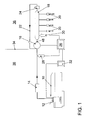
- Fig. 1 illustrates a non-return fuel system with a fuel tank 10, a electric fuel pump 12, a fuel filter 14, a reciprocating piston fuel pump or high-pressure pump (HDP) 16 with quantity control station, a high-pressure rail 18, a plurality of high-pressure injection valves (HDEV) 20, a return line 22, a pressure relief valve (DBV) 24, an engine control unit (ECU) 26, a low pressure sensor 28, a high pressure sensor 30 and a power output stage 32 for driving the fuel pump 12.
- Line 34 separates the fuel system into a high pressure side 36 and a low pressure side 36.
- the electric fuel pump (EKP) 12 serves as a feed pump for the Hub Piston Fuel Pump (HDP) 16.
- the Hub Piston Fuel Pump (HDP) 16 provides the Fuel pressure in the distribution bar or high-pressure rail 18 a.
- the high pressure injectors 20 are supplied from the high-pressure rail 20 with fuel.
- About the return line 22nd fuel flows back when the pressure in the high-pressure rail is a safety-critical one Exceeds limit. This can only occur in the event of a fault.
- a leakage line, not shown the Hub Piston Fuel Pump (HDP) 16 discharges fuel contained in the Hub Piston Fuel Pump (HDP) 16 escapes between piston and cylinder. This amount is however relatively small.
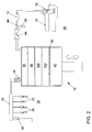
- the stroke piston fuel pump 16 includes, as shown in FIG. 2, a piston 40 in a cylinder 42 which performs a lifting movement. This lifting movement is divided into a downward and upward movement. In the downward movement is a displacement with fuel from the fuel tank 10 of the low pressure system 38 filled with fuel. In the upward movement the compression of the fuel takes place.
- a quantity control station in the form of a Rate control valve 44 disconnects during a predetermined portion of the upstroke Compression space from the supply side or low pressure side 38. During that Section of the upward movement of the piston 40, which is used to compress the fuel is to be used, the bulkhead 44 separates the connection between engine capacity the stroke piston fuel pump 16 and supply line 46.
- the quantity control 44 opens the connection between the displacement the stroke-piston fuel pump 16 and the supply line 46. A closing interval is created, which lies in the compression stroke of the stroke piston fuel pump 16.
- the position of the interval in the compression stroke is in principle freely selectable. Usually will either the closing or the opening time to one of the dead points of the movement of the piston 40 is placed. With both concepts it is possible the effective compression stroke adjust.
- the displacement is with the high pressure rail 18 of the high pressure system 36 via a check valve 48 is connected. As soon as the pressure in the displacement of the Hub piston fuel pump 16 is greater than the pressure in the high-pressure rail 18, the flows compressed fuel from the displacement of the stroke piston fuel pump 16 in the High Pressure Rail 18.
- the engine controller 26 ( Figure 1) provides the switching pulse to the flow control valve (44) of the quantity control station. The duration of this switching pulse sets Considering the piston speed and piston position fixed the effective stroke.
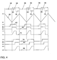
- Fig. 4 illustrates the control of the quantity control station 44 with the two different concepts.
- a graph 50 illustrates the movement of the piston 40 between a top dead center 52 and a bottom dead center 54, wherein a filling 56 and a compression 58 cyclically alternate.
- graph 62 shows a drive signal for the quantity control valve 44 between 0V and 12V, a graph 64 a state of the quantity control valve 44 between "open” 66, and “closed” 68 and a graph 70 a pressure in the compression chamber, the stroke-piston fuel pump 16 between a low pressure p low-pressure 72 in the low pressure system 38 and a high pressure p HD-rail 74 in the high-pressure system 36 or
- graph 78 shows a drive signal for the mass control valve 44 between 0V and 12V
- a graph 80 indicates a state of the mass control valve 44 between "open” 82 and “closed” 84 and a graph 86 a pressure in the compression chamber
- the stroke-piston fuel pump 16 between a low pressure p low-pressure 88 in the low pressure system 38 and a high pressure p HD-rail 90 in the high-pressure system 36 or high-pressure rail 18th
- the closing interval 60 or 76 of the quantity-adjusting mechanism 44 lies between the bottom dead center 54 and the top dead center 52 of the piston 40 of the reciprocating piston fuel pump 16 relative to a piston 40 moving upward in the cylinder 42. In principle, it does not matter if the closing interval immediately after passing through the bottom dead center 54 begins (concept I, arrow 60) or ends with reaching the top dead center 52 (concept II, arrow 76). Both concepts lead to pressure build-up. For energetic reasons, however, the second concept (arrow 76) is preferable.
- the compression process 60 or 76 is triggered by closing the quantity control station 44 with upwardly moving piston 40. The volume of fuel in the compression space at this moment is at approximately low pressure level. By the upward movement of the piston 40, the pressure increases.
- the check valve 48 opens and the fuel flows out of the compression space of the reciprocating piston fuel pump 16 into the high-pressure rail 18. Dies takes place as long as the pressure in the compression chamber above the pressure p HD rail is maintained in the high-pressure rail 18.
- the effective compression stroke is ended by opening the quantity-adjusting mechanism 44 or as soon as the piston 40 reaches its top dead center 52. Depending on the pump design and concept, a residual volume at the end of the compression process 58 may remain in the compression space of the reciprocating piston fuel pump 16.
- the fuel for example petrol
- changes its volume under pressure. This volume change results ⁇ V V 0 * ⁇ p * ⁇
- V 0 is an initial volume [mm 3]
- ⁇ p a change in pressure [bar]
- .DELTA.V a change in volume [mm 3].
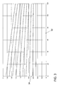
- the one compressibility number ⁇ [1 / bar] for the fluid to be compressed results, as a function of temperature and pressure, from a family of curves according to FIG. 3.
- FIG. 3 shows a pressure in [bar] and on a vertical axis 92 on a horizontal axis 92 Axis 94 the compressibility in [E-4 / bar].
- the curves correspond from top to bottom to a temperature of 413K, 393K, 373K, 353K, 333K, 313K, 293K, 273K, 253K and 233K.
- the density of the fuel for the respective operating point is first calculated.
- the fuel flows through first the lift-piston fuel pump 16, the fuel line and then the high-pressure rail 18. There is a heat transfer due to the contact of the fuel with the inner surfaces of the fuel-carrying components instead.
- the source of heat is the engine block or the ambient air in the engine compartment as well as the compression work in the reciprocating piston fuel pump 16. These heat inputs bear the following names t emotr , t eulr and t krailnp .
- the fuel flows into the compression space via the open quantity control 44 at the temperature t flvrhdp . There, the fuel is compressed and flows through the check valve 48 in the high-pressure rail 18. By this thermodynamic process takes place a temperature entry t krailnp in the fuel.
- the dependencies of t emotr , t eulr and t krailnp are determined empirically and stored in curves and maps .
- the dynamic behavior of the temperature t krail in the high-pressure rail 18 is detected.
- the time behavior of the filter is determined as a function of the fuel mass flow Q fuel ) and of the difference between t mot and t krailnp .
- the precontrol of the stroke piston fuel pump 16 is based on the calculation the stroke volume of the piston 40, which is used for the compression of the fuel shall be.
- This stroke volume is defined by closing and opening times the quantity control station 44, taking into account the pump geometry.
- the to be compressed Fuel volume results from the requirements of the engine controller 26 in terms Target fuel pressure in the high-pressure rail 18 and fuel quantity and the current Operating parameters, such as temperature and actual pressures.
- Ap soll_rail is defined as follows: ⁇ p soll_rail> 0 meant that the nominal pressure gradient is positive and Ap soll_rail ⁇ 0 meant the nominal pressure gradient däß negative.
- kmeshdp, tflvrhdp, nmot and p low pressure maps are addressed, which are empirically determined in the experiment.
- the delta crank angle dwms ⁇ s ⁇ g refers to that part of the rising edge of the drive cam for the reciprocating piston fuel pump that is conceptually used for the compression interval.
Landscapes
- Engineering & Computer Science (AREA)
- Chemical & Material Sciences (AREA)
- Combustion & Propulsion (AREA)
- Mechanical Engineering (AREA)
- General Engineering & Computer Science (AREA)
- Fuel-Injection Apparatus (AREA)
- Electrical Control Of Air Or Fuel Supplied To Internal-Combustion Engine (AREA)
Applications Claiming Priority (2)
| Application Number | Priority Date | Filing Date | Title |
|---|---|---|---|
| DE10351914A DE10351914A1 (de) | 2003-11-07 | 2003-11-07 | Verfahren zum Vorsteuern einer Hub Kolben Kraftstoffpumpe einer Brennkraftmaschine |
| DE10351914 | 2003-11-07 |
Publications (3)
| Publication Number | Publication Date |
|---|---|
| EP1529948A2 true EP1529948A2 (fr) | 2005-05-11 |
| EP1529948A3 EP1529948A3 (fr) | 2006-09-06 |
| EP1529948B1 EP1529948B1 (fr) | 2011-07-27 |
Family
ID=34428586
Family Applications (1)
| Application Number | Title | Priority Date | Filing Date |
|---|---|---|---|
| EP04021981A Expired - Lifetime EP1529948B1 (fr) | 2003-11-07 | 2004-09-16 | Procédé de préréglage de la pompe à carburante à course de piston variable d'un moteur à combustion |
Country Status (3)
| Country | Link |
|---|---|
| EP (1) | EP1529948B1 (fr) |
| AT (1) | ATE518054T1 (fr) |
| DE (1) | DE10351914A1 (fr) |
Cited By (1)
| Publication number | Priority date | Publication date | Assignee | Title |
|---|---|---|---|---|
| CN113339152A (zh) * | 2021-06-18 | 2021-09-03 | 中国北方发动机研究所(天津) | 一种高压共轨柴油机的轨压控制方法 |
Families Citing this family (2)
| Publication number | Priority date | Publication date | Assignee | Title |
|---|---|---|---|---|
| DE102008017160B3 (de) * | 2008-04-03 | 2009-07-09 | Continental Automotive Gmbh | Verfahren zum Bestimmen des effektiven Kompressibilitätsmoduls eines Einspritzsystems |
| DE102016119047B4 (de) * | 2016-10-07 | 2018-04-26 | Denso Corporation | Verfahren zur schnellen Ermittlung einer Kraftstoffmengenänderung |
Citations (2)
| Publication number | Priority date | Publication date | Assignee | Title |
|---|---|---|---|---|
| US6446610B1 (en) | 1999-02-26 | 2002-09-10 | Magneti Marelli France | Method and system for controlling pressure in a high pressure fuel pump supplying an internal combustion engine |
| DE10236654A1 (de) | 2002-01-09 | 2003-07-24 | Mitsubishi Electric Corp | Kraftstoff-Zufuhreinrichtung für einen Verbrennungsmotor |
Family Cites Families (2)
| Publication number | Priority date | Publication date | Assignee | Title |
|---|---|---|---|---|
| JP3287297B2 (ja) * | 1998-02-10 | 2002-06-04 | トヨタ自動車株式会社 | 燃料ポンプの制御装置 |
| DE10158950C2 (de) * | 2001-12-03 | 2003-10-02 | Bosch Gmbh Robert | Verfahren, Computerprogramm, Steuer- und Regelgerät zum Betreiben einer Brennkraftmaschine, sowie Brennkraftmaschine |
-
2003
- 2003-11-07 DE DE10351914A patent/DE10351914A1/de not_active Withdrawn
-
2004
- 2004-09-16 EP EP04021981A patent/EP1529948B1/fr not_active Expired - Lifetime
- 2004-09-16 AT AT04021981T patent/ATE518054T1/de active
Patent Citations (2)
| Publication number | Priority date | Publication date | Assignee | Title |
|---|---|---|---|---|
| US6446610B1 (en) | 1999-02-26 | 2002-09-10 | Magneti Marelli France | Method and system for controlling pressure in a high pressure fuel pump supplying an internal combustion engine |
| DE10236654A1 (de) | 2002-01-09 | 2003-07-24 | Mitsubishi Electric Corp | Kraftstoff-Zufuhreinrichtung für einen Verbrennungsmotor |
Cited By (1)
| Publication number | Priority date | Publication date | Assignee | Title |
|---|---|---|---|---|
| CN113339152A (zh) * | 2021-06-18 | 2021-09-03 | 中国北方发动机研究所(天津) | 一种高压共轨柴油机的轨压控制方法 |
Also Published As
| Publication number | Publication date |
|---|---|
| ATE518054T1 (de) | 2011-08-15 |
| EP1529948B1 (fr) | 2011-07-27 |
| DE10351914A1 (de) | 2005-09-15 |
| EP1529948A3 (fr) | 2006-09-06 |
Similar Documents
| Publication | Publication Date | Title |
|---|---|---|
| DE102007043565B4 (de) | Hochdruck-Kraftstoffpumpen-Steuervorrichtung für einen Verbrennungsmotor | |
| EP1042607B1 (fr) | Installation d'alimentation en carburant d'un moteur a combustion interne | |
| DE69925783T2 (de) | Brennstoffeinspritzsystem für eine Brennkraftmaschine | |
| DE102007000246B4 (de) | Treibstoffdrucksteuerung | |
| DE102015121059B4 (de) | Direkteinspritzungspumpensteuerung | |
| DE102011051062B4 (de) | Kraftstoffeinspritzsteuersystem für eine interne Verbrennungsmaschine | |
| DE102009014914A1 (de) | Vibrationen reduzierendes System, das eine Pumpe verwendet | |
| DE102015111949A1 (de) | Stromimpuls-Steuerverfahren für Kraftstoffsaugpumpen | |
| DE60000509T2 (de) | Verfahren und system zur druckregelung einer hochdruckkraftstoffpumpe für die kraftstoffversorgung eines verbrennungsmotors | |
| DE112007002520T5 (de) | Selektive Steuerung der Verdrängung einer Mehrkolbenkraftstoffpumpe | |
| DE102007000070B4 (de) | Pulsdauerverhältnissteuervorrichtung | |
| DE102016111377B4 (de) | Systeme und Verfahren zur Kraftstoffeinspritzung | |
| DE102014219459A1 (de) | Hochdruck-kraftstoffpumpensteuerung zur reduzierung von tickgeräuschen im leerlauf | |
| DE102014224796A1 (de) | Adaptives In-Erfahrung-Bringen des Arbeitszyklus für eine Hochdruck-Kraftstoffpumpe | |
| DE102015107020A1 (de) | Direkteinspritzpumpensteuerung für niedrige Kraftstoffpumpvolumen | |
| WO2014060292A1 (fr) | Procédé pour faire fonctionner un système d'injection de carburant présentant un chauffage de filtre à carburant et un système d'injection de carburant | |
| DE102014223322A1 (de) | Verfahren zur Erkennung der Pumpenorientierung einer Kraftstoffhochdruckpumpe | |
| DE102012103139B4 (de) | Kraftstoffinjektions-Steuerungsvorrichtung für einen Verbrennungsmotor | |
| DE112015002295T5 (de) | Vorrichtung zum Steuern einer Hochdruckpumpe | |
| EP2643582B1 (fr) | Procédé permettant de faire fonctionner un système de carburant d'un moteur à combustion interne | |
| DE112007002672T5 (de) | Selektive Steuerung der Verdrängung einer Mehrkolbenkraftstoffpumpe | |
| DE3382635T2 (de) | Verfahren und geraet fuer die genaue steuerung der kraftstoffeinspritzung in einer brennkraftmaschine. | |
| DE112014000612B4 (de) | Steuervorrichtung für eine Hochdruckpumpe | |
| DE602004005356T2 (de) | Speichereinspritzsystem für eine Brennkraftmaschine | |
| WO2006103147A1 (fr) | Regulation a deux positions d'une pompe haute pression de moteurs otto a injection directe |
Legal Events
| Date | Code | Title | Description |
|---|---|---|---|
| PUAI | Public reference made under article 153(3) epc to a published international application that has entered the european phase |
Free format text: ORIGINAL CODE: 0009012 |
|
| AK | Designated contracting states |
Kind code of ref document: A2 Designated state(s): AT BE BG CH CY CZ DE DK EE ES FI FR GB GR HU IE IT LI LU MC NL PL PT RO SE SI SK TR |
|
| AX | Request for extension of the european patent |
Extension state: AL HR LT LV MK |
|
| PUAL | Search report despatched |
Free format text: ORIGINAL CODE: 0009013 |
|
| AK | Designated contracting states |
Kind code of ref document: A3 Designated state(s): AT BE BG CH CY CZ DE DK EE ES FI FR GB GR HU IE IT LI LU MC NL PL PT RO SE SI SK TR |
|
| AX | Request for extension of the european patent |
Extension state: AL HR LT LV MK |
|
| RIC1 | Information provided on ipc code assigned before grant |
Ipc: F02D 41/38 20060101AFI20050228BHEP |
|
| 17P | Request for examination filed |
Effective date: 20070306 |
|
| AKX | Designation fees paid |
Designated state(s): AT BE BG CH CY CZ DE DK EE ES FI FR GB GR HU IE IT LI LU MC NL PL PT RO SE SI SK TR |
|
| 17Q | First examination report despatched |
Effective date: 20081020 |
|
| GRAP | Despatch of communication of intention to grant a patent |
Free format text: ORIGINAL CODE: EPIDOSNIGR1 |
|
| GRAS | Grant fee paid |
Free format text: ORIGINAL CODE: EPIDOSNIGR3 |
|
| GRAA | (expected) grant |
Free format text: ORIGINAL CODE: 0009210 |
|
| AK | Designated contracting states |
Kind code of ref document: B1 Designated state(s): AT BE BG CH CY CZ DE DK EE ES FI FR GB GR HU IE IT LI LU MC NL PL PT RO SE SI SK TR |
|
| REG | Reference to a national code |
Ref country code: GB Ref legal event code: FG4D Free format text: NOT ENGLISH |
|
| REG | Reference to a national code |
Ref country code: CH Ref legal event code: EP |
|
| REG | Reference to a national code |
Ref country code: DE Ref legal event code: R096 Ref document number: 502004012725 Country of ref document: DE Effective date: 20110922 |
|
| REG | Reference to a national code |
Ref country code: NL Ref legal event code: VDEP Effective date: 20110727 |
|
| PG25 | Lapsed in a contracting state [announced via postgrant information from national office to epo] |
Ref country code: PT Free format text: LAPSE BECAUSE OF FAILURE TO SUBMIT A TRANSLATION OF THE DESCRIPTION OR TO PAY THE FEE WITHIN THE PRESCRIBED TIME-LIMIT Effective date: 20111128 Ref country code: SE Free format text: LAPSE BECAUSE OF FAILURE TO SUBMIT A TRANSLATION OF THE DESCRIPTION OR TO PAY THE FEE WITHIN THE PRESCRIBED TIME-LIMIT Effective date: 20110727 Ref country code: NL Free format text: LAPSE BECAUSE OF FAILURE TO SUBMIT A TRANSLATION OF THE DESCRIPTION OR TO PAY THE FEE WITHIN THE PRESCRIBED TIME-LIMIT Effective date: 20110727 Ref country code: FI Free format text: LAPSE BECAUSE OF FAILURE TO SUBMIT A TRANSLATION OF THE DESCRIPTION OR TO PAY THE FEE WITHIN THE PRESCRIBED TIME-LIMIT Effective date: 20110727 |
|
| PG25 | Lapsed in a contracting state [announced via postgrant information from national office to epo] |
Ref country code: CY Free format text: LAPSE BECAUSE OF FAILURE TO SUBMIT A TRANSLATION OF THE DESCRIPTION OR TO PAY THE FEE WITHIN THE PRESCRIBED TIME-LIMIT Effective date: 20110727 Ref country code: SI Free format text: LAPSE BECAUSE OF FAILURE TO SUBMIT A TRANSLATION OF THE DESCRIPTION OR TO PAY THE FEE WITHIN THE PRESCRIBED TIME-LIMIT Effective date: 20110727 Ref country code: PL Free format text: LAPSE BECAUSE OF FAILURE TO SUBMIT A TRANSLATION OF THE DESCRIPTION OR TO PAY THE FEE WITHIN THE PRESCRIBED TIME-LIMIT Effective date: 20110727 Ref country code: GR Free format text: LAPSE BECAUSE OF FAILURE TO SUBMIT A TRANSLATION OF THE DESCRIPTION OR TO PAY THE FEE WITHIN THE PRESCRIBED TIME-LIMIT Effective date: 20111028 |
|
| REG | Reference to a national code |
Ref country code: IE Ref legal event code: FD4D |
|
| BERE | Be: lapsed |
Owner name: VOLKSWAGEN A.G. Effective date: 20110930 |
|
| PG25 | Lapsed in a contracting state [announced via postgrant information from national office to epo] |
Ref country code: IE Free format text: LAPSE BECAUSE OF FAILURE TO SUBMIT A TRANSLATION OF THE DESCRIPTION OR TO PAY THE FEE WITHIN THE PRESCRIBED TIME-LIMIT Effective date: 20110727 Ref country code: SK Free format text: LAPSE BECAUSE OF FAILURE TO SUBMIT A TRANSLATION OF THE DESCRIPTION OR TO PAY THE FEE WITHIN THE PRESCRIBED TIME-LIMIT Effective date: 20110727 Ref country code: MC Free format text: LAPSE BECAUSE OF NON-PAYMENT OF DUE FEES Effective date: 20110930 Ref country code: CZ Free format text: LAPSE BECAUSE OF FAILURE TO SUBMIT A TRANSLATION OF THE DESCRIPTION OR TO PAY THE FEE WITHIN THE PRESCRIBED TIME-LIMIT Effective date: 20110727 |
|
| REG | Reference to a national code |
Ref country code: CH Ref legal event code: PL |
|
| PG25 | Lapsed in a contracting state [announced via postgrant information from national office to epo] |
Ref country code: RO Free format text: LAPSE BECAUSE OF FAILURE TO SUBMIT A TRANSLATION OF THE DESCRIPTION OR TO PAY THE FEE WITHIN THE PRESCRIBED TIME-LIMIT Effective date: 20110727 Ref country code: IT Free format text: LAPSE BECAUSE OF FAILURE TO SUBMIT A TRANSLATION OF THE DESCRIPTION OR TO PAY THE FEE WITHIN THE PRESCRIBED TIME-LIMIT Effective date: 20110727 Ref country code: EE Free format text: LAPSE BECAUSE OF FAILURE TO SUBMIT A TRANSLATION OF THE DESCRIPTION OR TO PAY THE FEE WITHIN THE PRESCRIBED TIME-LIMIT Effective date: 20110727 |
|
| PLBE | No opposition filed within time limit |
Free format text: ORIGINAL CODE: 0009261 |
|
| STAA | Information on the status of an ep patent application or granted ep patent |
Free format text: STATUS: NO OPPOSITION FILED WITHIN TIME LIMIT |
|
| PG25 | Lapsed in a contracting state [announced via postgrant information from national office to epo] |
Ref country code: BE Free format text: LAPSE BECAUSE OF NON-PAYMENT OF DUE FEES Effective date: 20110930 Ref country code: DK Free format text: LAPSE BECAUSE OF FAILURE TO SUBMIT A TRANSLATION OF THE DESCRIPTION OR TO PAY THE FEE WITHIN THE PRESCRIBED TIME-LIMIT Effective date: 20110727 |
|
| 26N | No opposition filed |
Effective date: 20120502 |
|
| PG25 | Lapsed in a contracting state [announced via postgrant information from national office to epo] |
Ref country code: CH Free format text: LAPSE BECAUSE OF NON-PAYMENT OF DUE FEES Effective date: 20110930 Ref country code: LI Free format text: LAPSE BECAUSE OF NON-PAYMENT OF DUE FEES Effective date: 20110930 |
|
| REG | Reference to a national code |
Ref country code: DE Ref legal event code: R097 Ref document number: 502004012725 Country of ref document: DE Effective date: 20120502 |
|
| REG | Reference to a national code |
Ref country code: AT Ref legal event code: MM01 Ref document number: 518054 Country of ref document: AT Kind code of ref document: T Effective date: 20110916 |
|
| PG25 | Lapsed in a contracting state [announced via postgrant information from national office to epo] |
Ref country code: AT Free format text: LAPSE BECAUSE OF NON-PAYMENT OF DUE FEES Effective date: 20110916 |
|
| PG25 | Lapsed in a contracting state [announced via postgrant information from national office to epo] |
Ref country code: LU Free format text: LAPSE BECAUSE OF NON-PAYMENT OF DUE FEES Effective date: 20110916 |
|
| PG25 | Lapsed in a contracting state [announced via postgrant information from national office to epo] |
Ref country code: BG Free format text: LAPSE BECAUSE OF FAILURE TO SUBMIT A TRANSLATION OF THE DESCRIPTION OR TO PAY THE FEE WITHIN THE PRESCRIBED TIME-LIMIT Effective date: 20111027 |
|
| PG25 | Lapsed in a contracting state [announced via postgrant information from national office to epo] |
Ref country code: TR Free format text: LAPSE BECAUSE OF FAILURE TO SUBMIT A TRANSLATION OF THE DESCRIPTION OR TO PAY THE FEE WITHIN THE PRESCRIBED TIME-LIMIT Effective date: 20110727 |
|
| PG25 | Lapsed in a contracting state [announced via postgrant information from national office to epo] |
Ref country code: HU Free format text: LAPSE BECAUSE OF FAILURE TO SUBMIT A TRANSLATION OF THE DESCRIPTION OR TO PAY THE FEE WITHIN THE PRESCRIBED TIME-LIMIT Effective date: 20110727 Ref country code: ES Free format text: LAPSE BECAUSE OF FAILURE TO SUBMIT A TRANSLATION OF THE DESCRIPTION OR TO PAY THE FEE WITHIN THE PRESCRIBED TIME-LIMIT Effective date: 20111107 |
|
| REG | Reference to a national code |
Ref country code: FR Ref legal event code: PLFP Year of fee payment: 12 |
|
| REG | Reference to a national code |
Ref country code: FR Ref legal event code: PLFP Year of fee payment: 13 |
|
| REG | Reference to a national code |
Ref country code: FR Ref legal event code: PLFP Year of fee payment: 14 |
|
| REG | Reference to a national code |
Ref country code: FR Ref legal event code: PLFP Year of fee payment: 15 |
|
| P01 | Opt-out of the competence of the unified patent court (upc) registered |
Effective date: 20230523 |
|
| PGFP | Annual fee paid to national office [announced via postgrant information from national office to epo] |
Ref country code: GB Payment date: 20230926 Year of fee payment: 20 |
|
| PGFP | Annual fee paid to national office [announced via postgrant information from national office to epo] |
Ref country code: FR Payment date: 20230926 Year of fee payment: 20 Ref country code: DE Payment date: 20230930 Year of fee payment: 20 |
|
| REG | Reference to a national code |
Ref country code: DE Ref legal event code: R071 Ref document number: 502004012725 Country of ref document: DE |
|
| REG | Reference to a national code |
Ref country code: GB Ref legal event code: PE20 Expiry date: 20240915 |
|
| PG25 | Lapsed in a contracting state [announced via postgrant information from national office to epo] |
Ref country code: GB Free format text: LAPSE BECAUSE OF EXPIRATION OF PROTECTION Effective date: 20240915 |
|
| PG25 | Lapsed in a contracting state [announced via postgrant information from national office to epo] |
Ref country code: GB Free format text: LAPSE BECAUSE OF EXPIRATION OF PROTECTION Effective date: 20240915 |