EP1529914A2 - Détecteur sans contact et support de montage - Google Patents
Détecteur sans contact et support de montage Download PDFInfo
- Publication number
- EP1529914A2 EP1529914A2 EP04105475A EP04105475A EP1529914A2 EP 1529914 A2 EP1529914 A2 EP 1529914A2 EP 04105475 A EP04105475 A EP 04105475A EP 04105475 A EP04105475 A EP 04105475A EP 1529914 A2 EP1529914 A2 EP 1529914A2
- Authority
- EP
- European Patent Office
- Prior art keywords
- door
- transmitter
- sensor system
- mounting bracket
- contact sensor
- Prior art date
- Legal status (The legal status is an assumption and is not a legal conclusion. Google has not performed a legal analysis and makes no representation as to the accuracy of the status listed.)
- Withdrawn
Links
Images





Classifications
-
- H—ELECTRICITY
- H03—ELECTRONIC CIRCUITRY
- H03K—PULSE TECHNIQUE
- H03K17/00—Electronic switching or gating, i.e. not by contact-making and –breaking
- H03K17/94—Electronic switching or gating, i.e. not by contact-making and –breaking characterised by the way in which the control signals are generated
-
- E—FIXED CONSTRUCTIONS
- E05—LOCKS; KEYS; WINDOW OR DOOR FITTINGS; SAFES
- E05F—DEVICES FOR MOVING WINGS INTO OPEN OR CLOSED POSITION; CHECKS FOR WINGS; WING FITTINGS NOT OTHERWISE PROVIDED FOR, CONCERNED WITH THE FUNCTIONING OF THE WING
- E05F15/00—Power-operated mechanisms for wings
- E05F15/40—Safety devices, e.g. detection of obstructions or end positions
- E05F15/42—Detection using safety edges
- E05F15/43—Detection using safety edges responsive to disruption of energy beams, e.g. light or sound
-
- E—FIXED CONSTRUCTIONS
- E05—LOCKS; KEYS; WINDOW OR DOOR FITTINGS; SAFES
- E05F—DEVICES FOR MOVING WINGS INTO OPEN OR CLOSED POSITION; CHECKS FOR WINGS; WING FITTINGS NOT OTHERWISE PROVIDED FOR, CONCERNED WITH THE FUNCTIONING OF THE WING
- E05F15/00—Power-operated mechanisms for wings
- E05F15/40—Safety devices, e.g. detection of obstructions or end positions
- E05F15/42—Detection using safety edges
-
- E—FIXED CONSTRUCTIONS
- E05—LOCKS; KEYS; WINDOW OR DOOR FITTINGS; SAFES
- E05F—DEVICES FOR MOVING WINGS INTO OPEN OR CLOSED POSITION; CHECKS FOR WINGS; WING FITTINGS NOT OTHERWISE PROVIDED FOR, CONCERNED WITH THE FUNCTIONING OF THE WING
- E05F15/00—Power-operated mechanisms for wings
- E05F15/40—Safety devices, e.g. detection of obstructions or end positions
- E05F15/42—Detection using safety edges
- E05F15/43—Detection using safety edges responsive to disruption of energy beams, e.g. light or sound
- E05F2015/434—Detection using safety edges responsive to disruption of energy beams, e.g. light or sound with cameras or optical sensors
- E05F2015/435—Detection using safety edges responsive to disruption of energy beams, e.g. light or sound with cameras or optical sensors by interruption of the beam
- E05F2015/436—Detection using safety edges responsive to disruption of energy beams, e.g. light or sound with cameras or optical sensors by interruption of the beam the beam being parallel to the wing edge
-
- E—FIXED CONSTRUCTIONS
- E05—LOCKS; KEYS; WINDOW OR DOOR FITTINGS; SAFES
- E05Y—INDEXING SCHEME ASSOCIATED WITH SUBCLASSES E05D AND E05F, RELATING TO CONSTRUCTION ELEMENTS, ELECTRIC CONTROL, POWER SUPPLY, POWER SIGNAL OR TRANSMISSION, USER INTERFACES, MOUNTING OR COUPLING, DETAILS, ACCESSORIES, AUXILIARY OPERATIONS NOT OTHERWISE PROVIDED FOR, APPLICATION THEREOF
- E05Y2201/00—Constructional elements; Accessories therefor
- E05Y2201/40—Motors; Magnets; Springs; Weights; Accessories therefor
- E05Y2201/47—Springs
-
- E—FIXED CONSTRUCTIONS
- E05—LOCKS; KEYS; WINDOW OR DOOR FITTINGS; SAFES
- E05Y—INDEXING SCHEME ASSOCIATED WITH SUBCLASSES E05D AND E05F, RELATING TO CONSTRUCTION ELEMENTS, ELECTRIC CONTROL, POWER SUPPLY, POWER SIGNAL OR TRANSMISSION, USER INTERFACES, MOUNTING OR COUPLING, DETAILS, ACCESSORIES, AUXILIARY OPERATIONS NOT OTHERWISE PROVIDED FOR, APPLICATION THEREOF
- E05Y2201/00—Constructional elements; Accessories therefor
- E05Y2201/40—Motors; Magnets; Springs; Weights; Accessories therefor
- E05Y2201/50—Weights
-
- E—FIXED CONSTRUCTIONS
- E05—LOCKS; KEYS; WINDOW OR DOOR FITTINGS; SAFES
- E05Y—INDEXING SCHEME ASSOCIATED WITH SUBCLASSES E05D AND E05F, RELATING TO CONSTRUCTION ELEMENTS, ELECTRIC CONTROL, POWER SUPPLY, POWER SIGNAL OR TRANSMISSION, USER INTERFACES, MOUNTING OR COUPLING, DETAILS, ACCESSORIES, AUXILIARY OPERATIONS NOT OTHERWISE PROVIDED FOR, APPLICATION THEREOF
- E05Y2600/00—Mounting or coupling arrangements for elements provided for in this subclass
- E05Y2600/10—Adjustable
- E05Y2600/13—Adjustable by motors, magnets, springs or weights
Definitions
- the present invention relates to a sensor system for controlling movement of a door or other moving structure and, more particularly, a non-contact sensor system having a transmitter and a receiver with a control circuit for controlling movement of an overhead door or other moving structure.
- the present invention provides such a non-contact sensor system for a door which extends beyond a leading edge of the door and moves with the door, and which functions to sense the presence of items in the path of a downwardly moving door over substantially the entire range of movement of the door and prevent the door from ever contacting the sensed items.
- the present invention comprises a non-contact sensor system that controls movement of a door moving in a closing direction.
- the sensor system includes a generally rigid mounting bracket having an interfacing edge and configured to be mounted to a leading edge of the door, a transmitter and a receiver.
- the transmitter extends a first predetermined distance beyond the leading edge of the door at a first door side for transmitting a signal toward a second door side.
- the transmitter is attached to the rigid mounting bracket by a first moveable member.
- the first moveable member is formed of a resilient, flexible material and is configured to engage a surface when the door closes and moving between a first extended position and a first retracted position relative to the rigid mounting bracket.
- the receiver extends a second predetermined distance beyond the leading edge of the door at the second door side in relative alignment with the transmitter for detecting the signal and for generating an output signal when the transmitter signal is blocked.
- the receiver is attached to the door by a second moveable member.
- the second moveable member is formed of the resilient, flexible material and is configured to engage the surface when the door closes and moving between a second extended position and a second retracted position relative to the rigid mounting bracket. The output signal is suppressed when the second moveable member is in the second retracted position.
- the first and second moveable members each bend backwardly and upwardly as the door closes until the first and second moveable members reach the first and second retracted positions, respectively, and each unbends downwardly and forwardly to the first and second extended positions, respectively, relative to the leading edge of the door as the door opens.
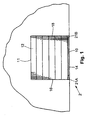
- Fig. 1 a first preferred embodiment of a non-contact sensor system 2 in accordance with the present invention.
- the non-contact sensor system 2 is employed to function with an existing actuator device or door controller 50 (Fig. 9) to cause a closing overhead door 12 or other structure to stop closing, to open or to move to a safe position when the non-contact sensor system 2 senses the presence of an object (not shown) within the path of the door 12.
- the non-contact sensor system 2 preferably causes the door 12 to stop before the door 12 contacts the object within the path of the door 12.
- the device 50 includes a limit switch 55 for detecting when the door 12 is in a nearly completely closed position. As shown in Fig.
- a doorway 11 is provided with the door 12 which, in the present embodiment is an overhead door, but need not be.
- the door 12 opens or closes under the control of the device 50.
- a sensing edge 10 is secured to a leading edge 14 of the door 12.
- the sensing edge 10 of the type described in the above-referenced patents or can be of any other suitable type.
- the non-contact sensor system 2 of the present invention can be used in place of a sensing edge 10, or in combination with a sensing edge 10.
- the non-contact sensor system 2 can also be used in connection with movable structures other than a door 12 such as a gate.
- a non-contact sensor system 2 controls movement of the door 12 moving in a first direction by actuation of the device 50.
- the sensor system 2 includes an emitter or transmitter 52 (hereinafter, "transmitter") extending a predetermined distance D beyond a leading edge 14 of the door 12 at a first door end 16 (Fig. 1) for transmitting a signal (not shown) toward a second door end 18 (Fig. 1).
- the transmitter 52 may be an infrared emitter, a light emitting diode (LED) or the like.
- the transmitter 52 is attached to the door 12 by a first moveable member 21A.
- the first moveable member 21A is capable of engaging an underlying surface (not shown) such as the ground or an overlying floor when the door 12 closes and moving to a retracted position.
- the sensor system 2 further includes a receiver 54 extending a predetermined distance D beyond the leading edge 14 of the door 12 at the second door end 18 and in relative alignment with the transmitter 52 for detecting the transmitted signal, and for generating an output signal (not shown) when the transmitted signal is not received because it is blocked.
- the receiver 54 is attached to the door 12 by a second moveable member 21B.
- the second moveable member 21B is capable of engaging the underlying surface when the door 12 closes and moving to a retracted position.
- the device 50 detects when the door 12 is nearly completely closed by the limit switch 55 which is mounted separately on the door 12 or device 50 from the moveable members 21A, 21B.
- the output signal is suppressed when the second moveable member 21B is in the retracted position.
- the retracted position is determined by the limit switch 55.
- Limit switch 55 may be an electromechanical limit switch, an inductive or capacitive proximity switch, a position transmitter with adjustable trip settings, or the like.
- a support member 22 (Fig. 5) includes a recess 23 proximate the first and second door ends 16, 18 and the first and second moveable members 21A, 21B move into the recess 23 as the door 12 closes to establish the retracted position.
- the foldable channel members are attached directly to the door 12, and the recess is directly in the door 12.
- the door 12 need not have a recess 23.
- the first and second moveable members 21A, 21B each include a foldable channel member 20.
- the foldable channel members 20 are structurally identical and are formed of a resilient, flexible material that folds into the recess 23 in the leading edge 14 of the door 12.
- the resilient material may be molded or extruded polymeric material such as polyvinyl chloride (PVC), polyethylene, high density polyethylene (HDPE), polypropylene, neoprene or the like, but the resilient material need not be polymeric.
- the resilient material may be other materials.
- each foldable channel member 20 has a first end 24 and a second end 26.
- the foldable channel member 20 further includes a flair 27, a first elongated section 31, a knee joint 25, a second elongated section 33, a right angle 35 and a tongue 29.
- the flair 27 is located proximate the first end 24 and may be generally rectangularly shaped, geometrically shaped, or the like, but is preferably cylindrically shaped, and is intended to contact the underlying surface during a normal closing operation of the door 12.
- the flair 27 has a cavity 27a for housing either a transmitter 52 or receiver 54.
- the first elongated section 31 extends from a portion of the flair 27 in a first curvilinear form with a first variable width to the knee joint 25.
- the second elongated section 33 extends from the knee joint 25 in a second curvilinear form with a second variable width to the right angle 35 proximate the second end 26.
- the knee joint 25 has an inner angle ⁇ measured between the first section 31 and the second section 33.
- the inner angle ⁇ may between about 20o and about 90o, but is preferably about 30o.
- the first curvilinear form and variable width, the second curvilinear form and variable width and the inner angle ⁇ are all selected in order to provide the foldable channel member 20 with a predisposition to fold onto itself. Other design criteria may also affect the selection of respective lengths, widths and or configurations of the first and second sections 31, 33 and inner angle ⁇ .
- the criteria include a width of the door 12, a braking distance of the door 12, and the like.
- the tongue 29 extends from right angle 35 for mounting the foldable channel member 20 directly to the door 12 or to the support member 22 (Fig. 5).
- the tongue 29 may be of a keyed shape such as a half moon shape, or the like, having first and second tongue slots 29a, 29b for mechanically mating with a similar but complimentary shaped groove 37 in the support member 22.
- the support member 22 is illustrated in Fig. 5.
- the support member 22 is comprised of a generally flat base 36, a pair of downwardly extending leg members 38 and a pair of upwardly extending channels 40.
- the channels 40 are employed for securing the support member 22, either directly or indirectly, to the leading edge 14 of a door 12 in a manner well known to those of ordinary skill in the art.
- the downwardly extending legs 38 form a recess 23 therebetween that receives the foldable channel members 20 as the door 12 closes against the underlying surface.
- One of the downwardly extending legs 38 includes the groove 37 for receiving the tongue 29 of the foldable channel member 29 as described above.
- the first section 31 moves in a direction of directional arrow C (Fig. 3D) toward the retracted position substantially in the recess 23 and approximately parallel with the second section 33.
- gravity and the resilient nature of the material biases the foldable channel member 20 toward the extended position causing the foldable channel member 20 to unfold in an opposite fashion.
- the length of the channel members 20 may be desirable to change a length of the foldable channel members 20 to account for such variables as braking distance, speed of the door, and the like.
- the length of the channel members 20 should be such that there is sufficient time/distance for the door to come to a complete stop before reaching the point at which the signal from the transmitter 52 to the receiver 54 is broken. It is preferable that the door 12 to never contact the object which breaks the signal.
- the length of the channel members 20 preferably extends at least the known distance beyond the leading edge 14 of the door 12 so that the door 12 does not strike the object which broke the signal.
- Adjusting the length of the foldable channel members 20 may be accomplished in many ways including making extensible sections for the foldable channel members 20 to allow telescoping adjustment of each section, changing the angle ⁇ , or making the sections of the foldable channel members 20 in two pieces with the pieces being moveably secured together using a slot/bolt arrangement or some other arrangement.
- the first moveable member 21A includes a transmitter 52 for establishing a signal which extends between the two aligned moveable members 21A, 21B when the moveable members 21A, 21B are in the extended position as illustrated in Fig. 3A.
- the second moveable member 21B includes a receiver 54. It will be appreciated by those of ordinary skill in the art that the location of the transmitter 52 and the receiver 54 could be reversed, if desired.
- the signal extends between the transmitter 52 and the receiver 54 and thus between the aligned first and second moveable members 21A, 21B so that as the door 12 moves toward the surface, any object in the path of the leading edge 14 of the door 12 breaks or occludes the signal to thereby stop the movement of the door 12 before the door 12 or the sensing edge 10 comes into actual contact with the object.
- a non-contact sensor system 2' includes a first moveable member 21A' and a second moveable member 21B' which are structurally the same and are located on opposite ends 16, 18 of the door 12. Accordingly, only one of the moveable members 21A', 21B' will be described below.
- Each moveable member 21A', 21B' includes a rotating channel member 20' which is pivotally secured to a support member 22' (Figs. 6-8) for rotation between an extended position and a retracted position.
- the rotating channel member 20' includes a first end 24' with an angle ⁇ that is between about 30o and 60o, but is preferably about 45o, and a second end 26' with an angle ⁇ that is between about 60o and 90o, but is preferably about 75o.
- the lower or distal portion of the first end 24' of the rotating channel member 20' includes a circular opening extending completely therethrough for receiving a pin member 28' which serves as an axle for supporting a wheel 30' which extends within a channel 32' of the rotating channel member 20'.
- the second end 26' of the channel member includes an opening 34' which is employed for pivotally supporting the rotating channel member 20' on the support member 22'.
- the rotating channel member 20' and the pin member 28' are preferably formed of a rigid, lightweight material, such as PVC, HDPE, Aluminum or the like. It will also be appreciated that the rotating channel member 20' may be made of a less rigid, more flexible material such as rubber, neoprene or the like. In this manner the rotating channel member 20' is less likely to damage an object which it may engage during movement of the door 12 or that might engage the rotating channel member 20' while the door 12 is open.
- the wheel 30' as illustrated in Fig. 2C is preferably formed of three flat washers to add weight to the distal end 24' of the channel member 20'. However, the wheel 30' could be formed of a single polymeric member or of any other suitable material.
- the support member 22' is illustrated in Figs. 6-8.
- the support member 22' is comprised of a generally flat base 36', a downwardly extending leg member 38' and a pair of upwardly extending channels 40'.
- the channels 40' are employed for securing the support member 22', either directly or indirectly to the leading edge 14 of a door 12 in a manner well known to those of ordinary skill in the art.
- the downwardly extending leg 38' includes an opening 42' which is employed for receiving a pin member 44' for pivotally connecting the rotating channel member 20' to the support member 22' as illustrated in Figs. 2A and 2B.
- a coil spring 46' is installed around the pin member 44' and within the channel 32'.
- the purpose of the coil spring 46' is to bias or urge the rotating channel member 20' toward the extended position as shown in phantom in Figs. 2A and 2B.
- the second end 26' limits movement of the channel member 22' to an angle y of between about 60o and about 90o, but preferably to approximately 75o with respect to the leading edge 14 of the door 12.
- a sensing edge 10 is secured to the leading edge 14 of the door 12, a portion of the sheath (not shown) of the sensing edge is removed to permit the rotating channel member 20' to pivot into the retracted position as shown in solid in Figs. 2A and 2B. If the door 12 does not include a sensing edge 10 then an opening is provided in a weather seal, forming a recess (not shown) along the leading edge 14 of the door 12 for receiving the rotating channel member 20' when in the retracted position.
- the support member 22' is preferably made of a rigid lightweight material, such as aluminum. However, a polymeric material may alternatively be employed.
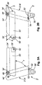
- Figs. 2A and 2B illustrate a non-contact sensor system 2' in accordance with the present invention, which includes a pair of generally aligned moveable members 21A', 21B' of the type described above which are secured proximate the first door end 16 and the second door end 18 of the leading edge 14 of a door 12 (not shown in Figs. 2A and 2B) and are oriented so that the channels 32' are aligned and facing each other.
- the wheels 30' engage the underlying surface causing the moveable members 20' to pivot from the extended position as illustrated in phantom in Figs.
- first and second moveable members 21A', 21B' are in the retracted position, the first and second moveable members 21A', 21B' are effectively encased within the distal ends of the sheath of any sensing edge 10 secured to the leading edge 14 of the door 12 or, if no sensing edge is employed, within the weather seal secured to the leading edge 14 of the door 12.
- the coil springs 46' and the force of gravity urge the channel members 20' to pivot back to the extended position as illustrated in phantom in Fig. 2B.
- the first moveable member 21A' includes a transmitter 52 for establishing a signal which extends between the two aligned moveable members 21A', 21B' when the moveable members 21A', 21B' are in the extended position as illustrated in phantom in Fig. 2A.
- the second moveable member 21B' includes a receiver 54. It will be appreciated by those of ordinary skill in the art that the location of the transmitter 52 and the receiver 54 could be reversed, if desired.
- the signal extends between the transmitter 52 and the receiver 54 within the two aligned moveable members 21A', 21B' so that as the door 12 moves downwardly, any object in the path of the door 12 breaks the signal and, thereby, stops the movement of the door 12 toward the surface before the door 12 comes into contact with the object.
- the rotatable channel members 20' may be oriented in a manner which differs from the orientation shown in Figs. 2A and 2B.
- the rotatable channel members 20' could each be rotated ninety degrees so that the rotatable channel members 20' are aligned with each other, but are both perpendicular to the principal surface of the door 12 and thus, extend into a facility.
- the orientation or location of the transmitter 52 and receiver 54 may also have to be changed to establish the signal between the first and second moveable members 21A', 21B'.
- the connection between the rotatable channel members 20' and the support members 22' may be adjustable to facilitate a different orientation of the channel members 20'.
- the length of the rotatable channel members 20' may be changed to account for such variables as braking distance, speed of the door, and the like.
- the length of the channel members 20' should be such that there is sufficient time/distance for the door 12 to come to a complete stop before reaching the point at which the signal from the transmitter 52 to the receiver 54 is broken. It is preferable that the door 12 to never contact the object which breaks the signal.
- the length of the channel members 20' preferably extends at least the known distance beyond the leading edge 14 of the door 12, so that the door 12 does not strike the object which broke the signal. Adjusting the length of the rotating channel members 20' may be accomplished in many ways including making telescoping rotating channel members 20' or making the rotating channel members 20' in two pieces with the pieces being moveably secured together using a slot/bolt arrangement or some other arrangement.
- the first moveable member 21A' may be moveably attached to the second moveable member 21B' by a connecting rod and a pivot or swivel joint or similar mechanical connection.
- the first and second moveable members 21A", 21B" each include a bendable channel member 20".
- the bendable channel members 20" are structurally identical and have a coil spring housing 39" that bends into a recess 23" in the leading edge 14 of the door 12.
- the coil spring housing 39'' may be constructed of resilient material such brass, steel, hard rubber or the like, but the resilient material may be other materials.
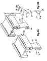
- Figs. 4A and 4B demonstrate that each bendable channel member 20" has a first end 24" and a second end 26".
- the bendable channel member 20" further includes an elongated section 31", a bending joint 25", and an attachment angle 35''.
- the elongated section 31'' may be generally rectangularly shaped, geometrically shaped, or the like, but is preferably cylindrically shaped, and is intended to contact the surface at least at the first end 24" during a normal closing operation.
- the housing 39'' has a cavity 27a'' for housing either the transmitter 52 or receiver 54.
- the first elongated section 31'' includes the bending joint 25" whose location is determined by an overall length of the bendable channel member 20", a length and degree of bend of the attachment angle 35'' and a stiffness of the material of the housing 39''.
- the attachment angle 35'' is for mounting the bendable channel member 20" directly to the leading edge 14 of the door 12 or to a support member 22".
- the attachment angle 35'' may be threaded or grooved for attachment with nuts or snap-rings, but may utilize other known attachment mechanisms.
- the support member 22" is comprised of a generally flat base 36", a pair of downwardly extending leg members 38" and a pair of upwardly extending channels 40".
- the channels 40" are employed for securing the support member 22", either directly or indirectly, to the leading edge 14 of a door 12 in a manner well known to those of ordinary skill in the art.
- the downwardly extending legs 38'' form a recess 23" that receives the bendable channel member 20" as the door 12 closes against the surface.
- the coil spring housing 39'' biases the bendable channel member 20" to the extended position.
- the first end 24" contacts the support, forcing the elongated section 31'' to bend at the bending joint 25'' in a direction toward the recess 23'' until the elongated section 31'' reaches the retracted position which is substantially in the recess 23'' as shown in phantom in Figs. 4A and 4B.
- the coil spring housing 39'' biases the bendable channel member 20", once again toward the extended position.
- the length of the foldable channel members 20" may be desirable to change the length of the foldable channel members 20" to account for such variables as braking distance, speed of the door, and the like.
- the length of the channel members 20" should be such that there is sufficient time/distance for the door to come to a complete stop before the door reaches the point at which the transmitted signal is broken. It is preferable that the door 12 to never contact the object which breaks the signal.
- the length of the channel members 20" preferably extends at least the known distance beyond the leading edge 14 of the door 12 so that the door 12 does not strike the object which broke the signal.
- Adjusting the length of the bendable channel members 20" may be accomplished in many ways including making stackable or threaded sections of the bendable channel members 20" to accommodate extension pieces or making the bendable channel members 20" in telescoping pieces with the pieces being moveably secured together using a set screw arrangement or some other arrangement.
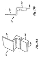
- the first and second moveable members 21''' are each mounted to a rigid mounting bracket or barrier 20"' or simply rigid mounting bracket 20"'.
- the rigid mounting bracket 20''' has an interfacing edge 25''' and is configured to be mounted to the leading edge 14 of the door 12.
- the rigid mounting bracket 20''' is preferably formed of a polymeric material such as Hytrel, a commercially available product available from E.I. DuPont De Nemours & Company, 1007 Market St. Wilmington, Delaware 19898.
- the rigid mounting bracket 20''' has a substantially flat mounting adapter 22''' for insertion into a recess or groove (not shown) in the leading edge 14 of the door 12.
- the flat mounting adapter 22''' can be thereafter secured by screws or bolts and the like as is known in the art.
- the interfacing edge 25''' is configured to firmly meet the surface or ground when the door 12 is closed thereby providing a seal from the outside of the door 12.
- the transmitter 52 is attached to the rigid mounting bracket 20''' by the first moveable member 21"'.
- the first moveable member 21''' is formed of a resilient, flexible material and is configured to engage a surface when the door closes and moving between a first extended position and a first retracted position relative to the rigid mounting bracket 20"'.
- the receiver 54 extends a second predetermined distance beyond the leading edge 14 of the door 12 at the second door side in relative alignment with the transmitter 52 for detecting the signal and for generating an output signal when the transmitter signal is blocked.
- the receiver 54 is attached to the rigid mounting bracket 20''' by the second moveable member 21'''.
- the second moveable member 21''' is also formed of the resilient, flexible material and is configured to engage the surface when the door 12 closes and move between a second extended position and a second retracted position relative to the rigid mounting bracket 20"'.
- Each moveable member 21''' includes a flare portion 27''' for engaging the surface similar to the first preferred embodiment. The output signal is suppressed when the second moveable member is in the second retracted position.
- the first and second moveable members 21''' may include a wiring slot 27a''' (Fig. 12D) so that lead wires from the transmitter 52 or receiver 54 can be pulled out through the wiring slot 27a''' thereby permitting the transmitter 52 or receiver 54 to be embedded farther into the first and second moveable members 21'''.
- This configuration also keeps such lead wires away from the sides 16, 18 of the door 12 in order to reduce possible rubbing and wear of the lead wires of the transmitter 52 or receiver 54.
- wiring holes 27b''' may be provided in the first and second moveable members 21''' for routing the lead wires therethrough.
- the first and second moveable members 21''' each bend backwardly and upwardly as the door 12 closes until the first and second moveable members 21''' reach the first and second retracted positions (solid in Fig. 12A), respectively, and each unbends downwardly and forwardly to the first and second extended positions, respectively, relative to the leading edge 14 of the door 12 as the door 12 opens (phantom in Fig. 12A).
- the first and second moveable members 21''' are protected from the elements, i.e., the rain, Sunlight, and extreme temperatures, thereby protecting the first and second moveable members 21''' and the transmitter 52 and receiver 54 therewith.
- Figs. 13A-13B show a rigid mounting bracket 20'''' in accordance with an alternate of the fourth preferred embodiment.
- the rigid mounting bracket 20'''' has a substantially flat mounting adapter 22'''' for insertion into a recess or groove (not shown) in the leading edge 14 of the door 12.
- the flat mounting adapter 22'''' can be thereafter secured by screws or bolts and the like as is known in the art.
- the interfacing edge 25'''' is configured to firmly meet the surface or ground when the door 12 is closed thereby providing a seal from the outside of the door 12.
- the transmitter 52 is attached to the rigid mounting bracket 20'''' by the first moveable member 21''' (Similar to Figs. 12A and 12D).
- the interfacing edge 25'''' of the rigid mounting bracket 20'''' is offset from the substantially flat mounting adapter 22'''' so that a front face 25a'''' will be at least partially flush with a front surface of the door 12.
- the first moveable member 21''' may also be somewhat protected or shielded by being partially under the door 12 when the door 12 is closed and the rigid mounting bracket 20'''' engages the surface.
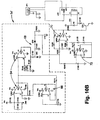
- Figs. 10A-11C illustrate preferred embodiments of the electronics of the present system.
- the transmitter 52 and the receiver 54 are electrically connected to a controller 56, which in turn is electrically connected to the device or door controller 50.
- the controller 56 includes circuitry for generating an appropriate transmit signal which is sent to the transmitter 52, as well as circuitry for receiving electrical signals from the receiver 54.
- the transmitter 52 is an infrared transmitter for transmitting an infrared signal
- the receiver 54 is an infrared receiver for detecting infrared signals.
- other technologies may be used instead of infrared, such as microwave, radio wave, visible light, laser beam and the like, without departing from the broad scope of the invention.
- the non-contact sensor system 2 has a control circuit 56, illustrated in Fig. 11C, coupled to the infrared receiver 54, illustrated in Fig. 11B, for receiving the output signal from the infrared receiver 54 and for sending a failure signal to the device 50 only if no infrared signal is received by the infrared receiver 54 for a predetermined time period.
- the infrared signal, the output signal and the failure signal may all be binary.
- the output signal may be a series of pulses each having a substantially similar width and a predetermined time between pulses, the pulses being generated only in the presence of the infrared signal being detected by the infrared receiver 54.
- the control circuit 56 has a microcontroller U1 which includes at least one input for receiving the output signal from the infrared receiver 54.
- the control circuit 56 may include an application specific integrated circuit (ASIC), a processor, a microprocessor, programmable array logic (PAL), or a combination of hardwired logic gates or the like.
- the microcontroller U1 in the control circuit 56 has at least one output for sending a failure signal to the device 50 that controls the movement of the door 12.
- the microcontroller U1 includes a program for counting continuously repeating pulses of the output signal from the infrared receiver 54 until a predetermined number of continuously repeating pulses accumulates and for causing the microcontroller U1 to send the failure signal to the device 50. By counting a number of pulses, the control circuit 56 reduces the possibility of sending out a failure signal based upon a false output signal. Additionally, the infrared transmitter 52 may be set for a gain greater than one so that the transmitted signal is stronger, enabling the non-contact sensor system 2 to detect signals over a greater distance and to compensate for lack of precise alignment between the infrared transmitter 52 and the infrared receiver 54.
- the non-contact sensor system 2 of the present invention due to its ability to have an increased gain and error reduction, is not susceptible to problems or false signals due to lack of precise alignment between the infrared transmitter 52 and the infrared receiver 54, noise, transients or other problems.
- Fig. 11A is a schematic circuit diagram of a preferred embodiment of a power supply circuit 58, for the present invention.
- the power supply circuit 58 comprises a voltage regulator IC U5, two Zener diodes D2, D13, a diode bridge rectifier DB1, a power-on light emitting diode (LED) D8, an inductance coil L1, and various biasing components C4, C9, C10, C15, R1, R9.
- the voltage regulator U5 is a National Semiconductor LM78M05C/TO and the diode bridge rectifier DB1 is a Diodes IncorporatedTM HD04DICT.
- a voltage with a potential of between about 7 to about 25 VDC is supplied, from an external power source (not shown), to the diode bridge rectifier DB1 which in conjunction with the Zener diode D2 ensures that a proper polarity voltage is supplied to the input of the voltage regulator IC U5.
- the voltage regulator IC U5 is capable of regulating an input voltage between about 7 to about 25 VDC to an output voltage between about 4.7 to about 5.3 VDC, but ideally to an output voltage between about 4.8 to about 5.2 VDC with a typical value of 5.0 VDC.
- the power supply circuit 58 supplies power at a regulated voltage to other devices in the related circuits depicted in Figs. 11B and 11C, described in detail below. It should be obvious to one skilled in the art to substitute other similar voltage regulators, bridge rectifiers, and the like, having different nominal input and output values without departing from the scope of the invention. In normal operation, power is continuously supplied to the power supply circuit 58, which in turn continuously provides power to the other parts of the circuit through commonly available electrical conductors, wires, jumpers or the like.
- Fig. 11B is a schematic circuit diagram of an infrared receiver 54 in accordance with the present embodiment.
- the infrared receiver 54 is supplied regulated power from the power supply circuit 58 at a voltage regulated between about 4.7 to about 5.3 VDC, but ideally to an output voltage between about 4.8 to about 5.2 VDC with a typical value of 5.0 VDC.
- Infrared receiver 54 includes an infrared receiver IC U4 and a filtering capacitor C11.
- the infrared receiver IC U4 in the present embodiment is a Panasonic PNA4611M infrared Photo IC.
- the combination of the infrared receiver IC U4 and the filtering capacitor C11 provides the capability of detecting a 36.7 kHz modulated infrared signal and outputting a low (zero) output as long as the modulated infrared signal is detected.
- Fig. 11C is a schematic circuit diagram of a control circuit 56 in accordance with the present embodiment.
- the control circuit 56 is supplied regulated power from the power supply circuit 58 at a voltage regulated between about 4.7 to about 5.3 VDC, but ideally to an output voltage between about 4.8 to about 5.2 VDC with a typical value of 5.0 VDC.
- the control circuit 56 comprises a microcontroller U1, an external clock/crystal CR1, a relay K1, a relay driver transistor Q2, various resistors R2, R5, R11, various capacitors C12, C14 and the infrared transmitter 52.
- the control circuit 56 also includes two other LED's: one for indicating relay-energized D7 and one for indicating signal-acquired D14.
- the main logic of the control circuit 56 is provided by the microcontroller U1 which may or may not need to use the external clock/crystal CR1 as a logic time base.
- the microcontroller U1 in the present embodiment is a MicrochipTM PIC16F84/SO microcontroller in combination with an external crystal CR1 modulated at 4 MHz.
- the particular microcontroller U1 includes on-chip FLASH memory for retaining the controlling programming code without external devices such as electronically programmable read only memory (EPROM's) or electronically erasable programmable read only memory (EEPROM's), or the like, but such devices may be used if desired.
- the relay K1 in the present embodiment, is a typical single pole single throw (SPST) dry contact type as is commonly known art; however, it would be obvious to one skilled in the art to substitute a variety of similar devices such as silicon controlled rectifiers (SCR's), power transistors, optical isolation devices, solid state switches, radio frequency transmitters, optical transmitters, and the like.
- SPST single pole single throw
- the infrared transmitter 52 includes an infrared transmitter driver transistor Q1, Zener diode D11, infrared LED D4 and biasing resistors R3, R10.
- the infrared LED D4 is a Unitech 1500C4DA-VFL
- the infrared transmitter driver transistor Q1 is a 2N7000 transistor
- the Zener diode is a 1N5232.
- An output of the microcontroller U1 connected to the infrared transmitter 52 is specifically connected to the infrared transmitter driver transistor Q1.
- the output of the microcontroller U1 connected to the infrared transmitter 52 is driven by the controlling programming in the microcontroller U1 to send the packets of ten voltage pulses.
- the infrared LED D4 Upon receiving the voltage pulses from the infrared transmitter driver transistor Q1, the infrared LED D4 transmits an infrared signal modulated at between about 20 kHz and 60 kHz but preferably at about 36.7 kHz.
- the infrared LED D4 Upon receiving the voltage pulses from the infrared transmitter driver transistor Q1, the infrared LED D4 transmits an infrared signal modulated at between about 20 kHz and 60 kHz but preferably at about 36.7 kHz.
- any of the components could be substituted with other commonly available circuit devices without departing from the spirit of the invention.
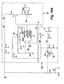
- Fig. 10A is a circuit diagram of a second preferred embodiment of a power supply circuitry 58' for an infrared transmitter 52'.
- the power supply circuitry 58' includes voltage regulator circuitry 60 and a square wave generator circuit 62.
- the square wave generator circuit 62 is comprised of an integrated circuit U10 and suitable biasing components which are arranged so that the integrated circuit generates an output square wave at a frequency between about five kilohertz (kHz) and about 130 kHz, but preferably at about ten kHz. It will be appreciated by those of ordinary skill in the art that any other suitable frequency could alternatively be employed.
- the output from the integrated circuit U10 on pin 3 is applied through a smoothing filter R70 and C90 to a switching transistor Q10 which switches on and off at the same frequency.
- the switching transistor Q10 is connected to an additional smoothing circuit and the infrared light emitting diode (LED) D10.
- Fig. 10B is a circuit diagram of a second preferred embodiment of a receiver circuit 54'.
- the receiver circuit 54' includes a pair of amplifiers 64 and an amplifier filter 66 for receiving electrical signals from an infrared photo diode D60.
- the amplified signals are then applied to a peak detector which effectively converts the received signals into DC signals.
- the DC signals are then applied to a comparator 70, the other input of which is provided by a dynamic reference generator 72. As long as the input signal to the comparator 70 is greater than the signal received from the reference generator 72, the output of the comparator 70 remains high.
- the output from the comparator 70 is applied to a switching transistor Q20, which is connected to the coil of a relay controller.
- the output signal from the comparator 70 is high, the transistor Q20 conducts and the coil of the relay functions to permit the door 12 to continue to close. If the infrared signal is blocked by the presence of an object in the path of the downwardly moving door 12, the output of the comparator 70 goes low turning off the transistor Q20 to change the state of the relay and, thereby, cause the door 12 to stop closing or to reverse itself and open.
- the door controller 50 deactivates the non-contact sensor system as the door gets close (within a few inches) to the surface.
- circuitry of Fig. 10A employed for driving the infrared transmitter 52' and the receiver circuitry of Fig. 10B are presented for the purpose of illustrating a first preferred embodiment of the invention and other circuitry could alternatively be employed.
- some other signal, other than an infrared signal may alternatively be transmitted and received between the two moveable members 21A, 21B.
- the present invention comprises a non-contact sensor system for a door having a transmitter, a receiver, and a control circuit. It will be appreciated by those skilled in the art that changes could be made to the embodiments described above without departing from the broad inventive concept thereof. It is understood, therefore, that this invention is not limited to the particular embodiments disclosed, but it is intended to cover modifications within the spirit and scope of the present invention as defined by the appended claims.
Landscapes
- Power-Operated Mechanisms For Wings (AREA)
Applications Claiming Priority (2)
| Application Number | Priority Date | Filing Date | Title |
|---|---|---|---|
| US701103 | 1985-02-13 | ||
| US10/701,103 US6920717B2 (en) | 2000-10-02 | 2003-11-04 | Non-contact sensor system and mounting barrier |
Publications (2)
| Publication Number | Publication Date |
|---|---|
| EP1529914A2 true EP1529914A2 (fr) | 2005-05-11 |
| EP1529914A3 EP1529914A3 (fr) | 2006-02-22 |
Family
ID=34435528
Family Applications (1)
| Application Number | Title | Priority Date | Filing Date |
|---|---|---|---|
| EP04105475A Withdrawn EP1529914A3 (fr) | 2003-11-04 | 2004-11-03 | Détecteur sans contact et support de montage |
Country Status (2)
| Country | Link |
|---|---|
| US (1) | US6920717B2 (fr) |
| EP (1) | EP1529914A3 (fr) |
Cited By (1)
| Publication number | Priority date | Publication date | Assignee | Title |
|---|---|---|---|---|
| ITTO20080596A1 (it) * | 2008-07-31 | 2010-02-01 | Pl S R L | Dispositivo di sicurezza per portoni a discesa verticale. |
Families Citing this family (19)
| Publication number | Priority date | Publication date | Assignee | Title |
|---|---|---|---|---|
| US7045764B2 (en) | 2002-10-17 | 2006-05-16 | Rite-Hite Holding Corporation | Passive detection system for detecting a body near a door |
| US7034682B2 (en) * | 2003-06-20 | 2006-04-25 | Rite-Hite Holding Corporation | Door with a safety antenna |
| US20050203056A1 (en) * | 2003-12-19 | 2005-09-15 | Aventis Pharma S.A. | Carboxyl-reduced derivatives of hyaluronic acid, preparation thereof, use thereof as a medicinal product and the pharmaceutical compositions containing them |
| DE102004014182B4 (de) * | 2004-03-23 | 2007-04-12 | Hörmann KG Brockhagen | Tor |
| US7420347B2 (en) * | 2004-10-04 | 2008-09-02 | The Chamberlain Group, Inc. | System and method for using a capacitive door edge sensor |
| ITMI20050832A1 (it) * | 2005-05-10 | 2006-11-11 | Ferport S A S Di M Biassoni & C | Porta scorrevole |
| US20060280657A1 (en) * | 2005-06-13 | 2006-12-14 | Farina Edward F | Snap fit sensor mounting bracket |
| DE102005038617A1 (de) * | 2005-08-16 | 2007-03-01 | Webasto Ag | Einklemmschutzvorrichtung im Kraftfahrzeugbereich |
| DE202005016087U1 (de) * | 2005-10-13 | 2007-02-22 | Marantec Antriebs- Und Steuerungstechnik Gmbh & Co. Kg | Gebäude- oder Hofabschlussvorrichtung |
| JP2007308929A (ja) * | 2006-05-17 | 2007-11-29 | Aisin Seiki Co Ltd | 車両ドア開閉制御装置 |
| US10246927B2 (en) | 2010-10-05 | 2019-04-02 | Miller Edge, Inc. | Sensing edge |
| EP2439368A3 (fr) | 2010-10-05 | 2014-07-23 | Miller Edge, Inc. | Cavité de stockage d'une résistance dans une fiche d'un bord de détection |
| US8832996B2 (en) * | 2010-10-05 | 2014-09-16 | Miller Edge, Inc. | Sensing edge |
| US8495834B2 (en) * | 2011-01-07 | 2013-07-30 | Linear Llc | Obstruction detector power control |
| DE102011082883A1 (de) * | 2011-09-16 | 2013-03-21 | Trumpf Laser Gmbh + Co. Kg | Schutztüre für eine Bearbeitungsmaschine |
| US20130086841A1 (en) * | 2011-10-10 | 2013-04-11 | William M. Luper | Overhead Door Object Detection Apparatus |
| ITVR20120024U1 (it) * | 2012-05-17 | 2013-11-18 | R I B S R L | Struttura di porta |
| DE102020110503A1 (de) * | 2020-04-17 | 2021-10-21 | EFAFLEX INŽENIRING d.o.o. Ljubljana | Sicherheitsvorrichtung für ein Hubtor und Hubtor mit einer solchen Sicherheitsvorrichtung |
| US12281504B2 (en) * | 2022-01-25 | 2025-04-22 | Waspw, Llc | Door protection device |
Family Cites Families (39)
| Publication number | Priority date | Publication date | Assignee | Title |
|---|---|---|---|---|
| US1576950A (en) | 1921-04-11 | 1926-03-16 | Nat Pneumatic Co | Safety shoe-tripping mechanism for doors |
| US1634665A (en) | 1921-04-11 | 1927-07-05 | Hedley Frank | Control mechanism for motor-actuated doors |
| GB451936A (en) | 1935-02-05 | 1936-08-05 | Frederick Haslam | Improvements in or relating to power operated shutters or doors |
| US2135131A (en) | 1937-02-15 | 1938-11-01 | Elevator Supplies Co Inc | Sensitive door edge structure |
| US2476111A (en) | 1945-07-07 | 1949-07-12 | Opalek Charles | Mechanism for automatic stopping and reversal of electromechanically operated doors |
| US3168165A (en) | 1962-06-11 | 1965-02-02 | Serge Elevator Company Inc | Protective door reversing means |
| US3537211A (en) | 1967-06-26 | 1970-11-03 | Guilbert Inc | Reversing edge control for car doors |
| DE2917797C2 (de) | 1979-05-03 | 1982-06-24 | Gebr. Bode & Co, 3500 Kassel | Einklemmsicherung für selbsttätig öffnende und schließende Türen |
| US4663885A (en) * | 1984-03-13 | 1987-05-12 | Stibolt Paul E | Security window cover |
| SE459873B (sv) | 1986-10-09 | 1989-08-14 | Nomafa Ab | Saekerhetsanordning, i synnerhet foer s k rullportar |
| DE3709592A1 (de) | 1987-03-24 | 1988-10-13 | Schieffer Gmbh Co Kg | Schnellauftor |
| US4809469A (en) * | 1987-03-25 | 1989-03-07 | Klein Mathew M | Assembly of clip and door frame members |
| US4984658A (en) | 1990-01-22 | 1991-01-15 | The Peelle Company | Car gate reversing edge |
| US5222287A (en) * | 1991-07-16 | 1993-06-29 | Fleetwood Enterprises, Inc. | Method of making a compartment door for recreational vehicles |
| US5233185A (en) | 1992-02-28 | 1993-08-03 | Gmi Holdings, Inc. | Light beam detector for door openers using fiber optics |
| US5231948A (en) * | 1992-06-30 | 1993-08-03 | Tempress, Inc. | Hatch with improved latch and hinge assembly |
| USD348316S (en) * | 1992-06-30 | 1994-06-28 | Tempress Incorporated | Hatch |
| US5426293A (en) | 1993-04-29 | 1995-06-20 | Miller Edge | Sensing edge having a photoelectric switch positioned therein |
| US5625980A (en) | 1993-09-15 | 1997-05-06 | Rmt Associates | Garage door opener with remote safety sensors |
| US5596840A (en) | 1993-09-15 | 1997-01-28 | Rmt Associates, Inc. | Garage door opener with remote safety sensors |
| US5602370A (en) | 1995-09-01 | 1997-02-11 | Kau; David | Safety switch for electric rolling doors |
| US5743320A (en) | 1995-12-29 | 1998-04-28 | Mckeon Rolling Steel Door Company, Inc. | Obstruction-responsive brake actuator for fire door or the like |
| US5810412A (en) * | 1996-03-14 | 1998-09-22 | Sundowner Trailers, Inc. | Guard for animal transporting vehicles |
| USD390525S (en) * | 1996-04-02 | 1998-02-10 | Thetford Corporation | RV door unit |
| US5728984A (en) | 1996-11-20 | 1998-03-17 | Miller Edge, Inc. | Sensing safety edge systems |
| US5832665A (en) | 1996-04-29 | 1998-11-10 | Miller Edge, Inc. | Sensing edge |
| DE19647720B4 (de) | 1996-11-19 | 2004-05-13 | Wampfler Aktiengesellschaft | Schließkantensicherheitsleiste |
| IT237463Y1 (it) * | 1997-04-30 | 2000-09-13 | Campisa Srl | Serranda ad azionamento rapido in particolare per aperture di edificiindustriali |
| DE19747830C2 (de) * | 1997-10-23 | 2003-11-06 | Joerg Brech | Vorrichtung zur Sicherung der Schließkante eines im wesentlichen translatorisch verstellbaren, motorisch angetriebenen Bauteiles |
| DE19804801C1 (de) * | 1998-02-09 | 1999-07-08 | Dorma Gmbh & Co Kg | Befestigung von Endkappen an Gehäusen, die aus Profilen bestehen |
| US6082046A (en) | 1998-02-25 | 2000-07-04 | Simmons; Kevin A. | Overhead door sensor mounting bracket |
| US5962825A (en) | 1998-06-15 | 1999-10-05 | Miller Edge, Inc. | Universal sensing edge |
| USD437312S1 (en) * | 1998-12-16 | 2001-02-06 | Mitel Corporation | Plastic door |
| US6286257B1 (en) * | 1999-02-22 | 2001-09-11 | Rytec Corporation | Overhead door with dual safety-edge |
| US6427382B2 (en) * | 1999-02-22 | 2002-08-06 | Rytec Corporation | Dual safety-edge for an overhead door |
| US6176039B1 (en) | 1999-11-22 | 2001-01-23 | Terry A. Craig | Garage door mounted object sensor system |
| US6502871B1 (en) * | 2000-11-28 | 2003-01-07 | Tempress Products, Lp | Rotary latch system and method |
| US6509561B1 (en) * | 2001-01-12 | 2003-01-21 | John Perry Scott | Protective cover assembly for garage door sensors |
| WO2002063126A1 (fr) * | 2001-02-02 | 2002-08-15 | Hörmann KG Brockhagen | Element d'etancheite pour un vantail de porte, vantail de porte pourvu d'un tel element d'etancheite et porte |
-
2003
- 2003-11-04 US US10/701,103 patent/US6920717B2/en not_active Expired - Lifetime
-
2004
- 2004-11-03 EP EP04105475A patent/EP1529914A3/fr not_active Withdrawn
Cited By (1)
| Publication number | Priority date | Publication date | Assignee | Title |
|---|---|---|---|---|
| ITTO20080596A1 (it) * | 2008-07-31 | 2010-02-01 | Pl S R L | Dispositivo di sicurezza per portoni a discesa verticale. |
Also Published As
| Publication number | Publication date |
|---|---|
| US20040088922A1 (en) | 2004-05-13 |
| EP1529914A3 (fr) | 2006-02-22 |
| US6920717B2 (en) | 2005-07-26 |
Similar Documents
| Publication | Publication Date | Title |
|---|---|---|
| EP1529914A2 (fr) | Détecteur sans contact et support de montage | |
| US6651385B2 (en) | Retractable non-contact sensor system | |
| US7513293B2 (en) | Method and apparatus for directionally controlling a movable partition | |
| US5040331A (en) | Remote controlled opening device | |
| US7046129B2 (en) | Device for detecting an obstacle in the opening range of a movable closure element | |
| US6683296B2 (en) | Sensor system for controlling movement of a door using a time-delay failure signal | |
| US20050210752A1 (en) | Drive tension sensor for a powered door | |
| KR101746936B1 (ko) | 벨트리스 타입 자동문 개폐시스템 | |
| US7420347B2 (en) | System and method for using a capacitive door edge sensor | |
| CA2343117A1 (fr) | Systeme captif formant indicateur d'aiguillage, a cible de position de commande d'aiguillage unique | |
| US20120199463A1 (en) | Furniture element with operating arrangement for an electrical device | |
| EP2075399A2 (fr) | Bordure de sécurité pour portes motorisées | |
| GB2368176A (en) | Proximity sensor employing a flexible capacitive sensing element | |
| MXPA06011291A (es) | Dispositivo de operacion de cierre motorizado con sistema de control electronico. | |
| US20040075961A1 (en) | Movable barrier safety control | |
| CA2157763C (fr) | Montant extensible a manoeuvre electrique pour cloisons mobiles | |
| KR20240042028A (ko) | 가동 라인-유지 디바이스, 에너지 체인 등을 지지하기 위한 시스템 | |
| KR20090009363U (ko) | 자동문 안전센서 장치 | |
| PL1843004T3 (pl) | Profil końcowy żaluzji urządzenia zabezpieczającego | |
| KR200316155Y1 (ko) | 도어록 장치 | |
| US20250369503A1 (en) | Anti-Pinch Electric Linear Actuator | |
| ITVI20080170A1 (it) | Dispositivo di sicurezza per un cancello o per una porta scorrevole azionata da un motore | |
| EP1722059B1 (fr) | Porte sectionnelle | |
| JP2005042485A (ja) | 電動シャッター制御装置 | |
| JP2020139271A (ja) | 防護装置、自動ドアシステムおよび防護装置の可動方法 |
Legal Events
| Date | Code | Title | Description |
|---|---|---|---|
| PUAI | Public reference made under article 153(3) epc to a published international application that has entered the european phase |
Free format text: ORIGINAL CODE: 0009012 |
|
| AK | Designated contracting states |
Kind code of ref document: A2 Designated state(s): AT BE BG CH CY CZ DE DK EE ES FI FR GB GR HU IE IS IT LI LU MC NL PL PT RO SE SI SK TR |
|
| AX | Request for extension of the european patent |
Extension state: AL HR LT LV MK YU |
|
| RIN1 | Information on inventor provided before grant (corrected) |
Inventor name: ANDERSON, MICHAEL Inventor name: MILLER, BEARGE D. Inventor name: CASTELLO, TIMOTHY Inventor name: LEIGH, GARY |
|
| PUAL | Search report despatched |
Free format text: ORIGINAL CODE: 0009013 |
|
| AK | Designated contracting states |
Kind code of ref document: A3 Designated state(s): AT BE BG CH CY CZ DE DK EE ES FI FR GB GR HU IE IS IT LI LU MC NL PL PT RO SE SI SK TR |
|
| AX | Request for extension of the european patent |
Extension state: AL HR LT LV MK YU |
|
| 17P | Request for examination filed |
Effective date: 20060811 |
|
| AKX | Designation fees paid |
Designated state(s): AT BE BG CH CY CZ DE DK EE ES FI FR GB GR HU IE IS IT LI LU MC NL PL PT RO SE SI SK TR |
|
| 17Q | First examination report despatched |
Effective date: 20071001 |
|
| STAA | Information on the status of an ep patent application or granted ep patent |
Free format text: STATUS: THE APPLICATION IS DEEMED TO BE WITHDRAWN |
|
| 18D | Application deemed to be withdrawn |
Effective date: 20160628 |