EP1529883B1 - Mur anti-bruit - Google Patents
Mur anti-bruit Download PDFInfo
- Publication number
- EP1529883B1 EP1529883B1 EP04026119A EP04026119A EP1529883B1 EP 1529883 B1 EP1529883 B1 EP 1529883B1 EP 04026119 A EP04026119 A EP 04026119A EP 04026119 A EP04026119 A EP 04026119A EP 1529883 B1 EP1529883 B1 EP 1529883B1
- Authority
- EP
- European Patent Office
- Prior art keywords
- noise protection
- section
- protection element
- profile
- wall
- Prior art date
- Legal status (The legal status is an assumption and is not a legal conclusion. Google has not performed a legal analysis and makes no representation as to the accuracy of the status listed.)
- Expired - Lifetime
Links
- 238000013016 damping Methods 0.000 title description 2
- 229910052751 metal Inorganic materials 0.000 claims abstract description 12
- 239000002184 metal Substances 0.000 claims abstract description 12
- 230000007935 neutral effect Effects 0.000 claims description 15
- 239000000835 fiber Substances 0.000 claims description 8
- 229910000838 Al alloy Inorganic materials 0.000 claims description 6
- 229910052782 aluminium Inorganic materials 0.000 claims description 5
- XAGFODPZIPBFFR-UHFFFAOYSA-N aluminium Chemical compound [Al] XAGFODPZIPBFFR-UHFFFAOYSA-N 0.000 claims description 5
- 238000005452 bending Methods 0.000 claims description 4
- 238000004873 anchoring Methods 0.000 claims description 2
- 229920001971 elastomer Polymers 0.000 claims description 2
- 239000004411 aluminium Substances 0.000 claims 1
- 230000000284 resting effect Effects 0.000 claims 1
- 230000000630 rising effect Effects 0.000 claims 1
- 230000004888 barrier function Effects 0.000 abstract description 14
- 239000011358 absorbing material Substances 0.000 abstract description 2
- 238000007789 sealing Methods 0.000 description 8
- 239000000565 sealant Substances 0.000 description 5
- 238000010276 construction Methods 0.000 description 4
- 238000009413 insulation Methods 0.000 description 4
- 238000001125 extrusion Methods 0.000 description 3
- 230000000087 stabilizing effect Effects 0.000 description 3
- 230000002349 favourable effect Effects 0.000 description 2
- 238000004519 manufacturing process Methods 0.000 description 2
- 230000009467 reduction Effects 0.000 description 2
- 239000011343 solid material Substances 0.000 description 2
- 229920002943 EPDM rubber Polymers 0.000 description 1
- 240000000581 Triticum monococcum Species 0.000 description 1
- 229920002522 Wood fibre Polymers 0.000 description 1
- 230000002745 absorbent Effects 0.000 description 1
- 239000002250 absorbent Substances 0.000 description 1
- 239000011324 bead Substances 0.000 description 1
- 230000015572 biosynthetic process Effects 0.000 description 1
- 239000004568 cement Substances 0.000 description 1
- 239000002131 composite material Substances 0.000 description 1
- 238000006073 displacement reaction Methods 0.000 description 1
- 238000007688 edging Methods 0.000 description 1
- 230000001771 impaired effect Effects 0.000 description 1
- 238000009434 installation Methods 0.000 description 1
- 239000000463 material Substances 0.000 description 1
- 239000011490 mineral wool Substances 0.000 description 1
- 230000004048 modification Effects 0.000 description 1
- 238000012986 modification Methods 0.000 description 1
- 239000010935 stainless steel Substances 0.000 description 1
- 229910001220 stainless steel Inorganic materials 0.000 description 1
- 239000002025 wood fiber Substances 0.000 description 1
Images

Classifications
-
- E—FIXED CONSTRUCTIONS
- E01—CONSTRUCTION OF ROADS, RAILWAYS, OR BRIDGES
- E01F—ADDITIONAL WORK, SUCH AS EQUIPPING ROADS OR THE CONSTRUCTION OF PLATFORMS, HELICOPTER LANDING STAGES, SIGNS, SNOW FENCES, OR THE LIKE
- E01F8/00—Arrangements for absorbing or reflecting air-transmitted noise from road or railway traffic
- E01F8/0005—Arrangements for absorbing or reflecting air-transmitted noise from road or railway traffic used in a wall type arrangement
- E01F8/0047—Arrangements for absorbing or reflecting air-transmitted noise from road or railway traffic used in a wall type arrangement with open cavities, e.g. for covering sunken roads
- E01F8/0064—Perforated plate or mesh, e.g. as wall facing
- E01F8/007—Perforated plate or mesh, e.g. as wall facing with damping material
-
- E—FIXED CONSTRUCTIONS
- E01—CONSTRUCTION OF ROADS, RAILWAYS, OR BRIDGES
- E01F—ADDITIONAL WORK, SUCH AS EQUIPPING ROADS OR THE CONSTRUCTION OF PLATFORMS, HELICOPTER LANDING STAGES, SIGNS, SNOW FENCES, OR THE LIKE
- E01F8/00—Arrangements for absorbing or reflecting air-transmitted noise from road or railway traffic
- E01F8/0005—Arrangements for absorbing or reflecting air-transmitted noise from road or railway traffic used in a wall type arrangement
- E01F8/0011—Plank-like elements
Definitions
- the invention relates to a noise protection element for the construction of noise barriers, with a front wall, a rear wall, an upper side wall and a lower side wall having hollow box profile, which is composed of a plurality of interconnected by a profile connection profile sheets and in the cavity of a substantially from the bottom up to the upper side wall and arranged over the length of the hollow box profile symmetrically to the median plane extending between the front wall and rear wall Schalldämmianu or can be arranged.
- the invention further relates to a noise barrier, which is formed from a plurality of corresponding noise protection elements.
- the preferred field of application of the noise protection elements according to the invention relates to e.g. Noise barriers at high-speed railway lines and airports.
- noise barriers are hereby built from individual noise protection elements that can be installed vertically or horizontally together and thereby anchored, at least when mounting in horizontal position, between towering and fixed in a ground foundation columns or posts with I-profile.
- the profile sheets of the hollow box profile preferably made of aluminum and soundproofing elements in the soundproofing elements of sufficient thickness of sound-absorbing materials such as mineral wool in particular are used.
- the noise protection source facing surface of the noise protection elements is often provided for reasons of better sound refraction with recesses such as a hole pattern.
- a generic noise protection element which consists of a total of four profile sheets, two of which are designed as large-format, roll-formed aluminum mold sheet with beads and form the front wall and the rear wall, and two more are designed as extrusions, which in the assembled state form the upper and lower side wall, is from the DE 296 09 237 U1 known.
- the front wall and rear wall are connected to the two side walls each by means of a mutual Hakenumgriffs with inclined locking surfaces.
- the generic noise protection element can be produced with comparatively low production and assembly costs and has proven itself in use, in particular on roads and conventional railway lines.
- a noise protection element is known, which is composed of two half-shell-shaped profile sheets whose upper and lower side walls forming legs are connected by a longitudinal locking form-fitting manner. While one of the legs is angled approximately 90 ° to the front or rear wall, runs the other leg following a likewise bent by 90 ° piece as a trapezoidal nose, so that adjacent noise protection elements in the formation of a noise barrier can lie directly or with the interposition of a DämmstMails together.
- the hollow box profile is composed of a first and a second half-shell-shaped profile sheet, wherein the first profile sheet integrally forms the front wall and a portion of the lower and a portion of the upper side wall, said second profile sheet integrally the rear wall and a portion of the lower and a Part of the upper side wall forms, and wherein the first and the second profile sheet at the upper and at the lower side wall in each case at the level of the median plane, throughout the length of the hollow box profile, are interconnected by a positive profile connection.
- the object of the invention is to provide a noise protection element and a noise barrier, which also withstand the extreme loads on high-speed rail lines and similar applications in which high dynamic pressure and Sogbelastept occur, and in this case are inexpensive to manufacture and assemble.
- the positive-locking profile connection is secured by means of at least one additional locking means, wherein the profile connection and the locking means are arranged at the level of the median plane of the noise protection element, thus in a region which is neutral with respect to dynamic bending and dynamic torsion Fiber or, neutral plane of the noise protection element forms.
- the inventors of the present application attributed the low stability of the generic noise protection elements to high dynamic loads, which in the passage of a high-speed train on the noise barrier and thus to the individual noise protection elements the noise barrier are exercised.
- the noise protection element with essentially only two half-shell-shaped profiled sheets which form integrally formed on the front or rear wall sections, the two side walls, wherein the profile connection between the two half-shell-shaped profile sheets is concentrated on the height or the region of the median plane ,
- the actual weak points of the hollow box profile namely the profile connections, are arranged in the region of least stress.
- the profile connection is secured by means of at least one locking means to prevent eicher even with extreme dynamic loads L Kunststoffsverachiebungen or other shifts between the two sheets.
- the locking means is arranged at the level of the median plane, and thus again in the region of the neutral fiber or neutral plane of the noise protection element.
- both profile sheets are preferably made of extruded profiles, wherein the profile sheets preferably consist of an aluminum alloy, in particular a high-vibration or corschwingbelastbaren aluminum alloy.
- the joining elements for the profile connection of both profiled sheets or half shells can already be formed during primary forming.
- both profiled sheets can be provided with corresponding to their stress adapted zones of different profile thickness or profile contour already in the prototyping become.
- the invention provides in particular that both profile sheets have an identical profile shape.
- the locking means may comprise plug-in means.
- screw means such as fastening screws form the additional locking means for the profile connection.
- both Pofilbleche can form half-shells and for the joining of the positive profile connection of both profile sheets, the two profile sheets can be integrally obtained a first joining element and a second joining element, the form-fitting together can be locked.
- the profile sheets are therefore half-shells with integrally formed and the profile connection forming joining elements.
- the plug or screw means in mutually aligned, the joining elements, in particular the hollow chamber or its wall and the profile section at least partially cross through holes or tapped holes intervene.
- the joining elements in particular the hollow chamber or its wall and the profile section at least partially cross through holes or tapped holes intervene.
- evolveze-ßigerweise can then be attached to the two end faces of the noise protection element at the same time a front side cover with the locking means.
- the profile section and the hollow chamber groove may in particular be rectangular.
- the profile section may in particular have a block profile and the hollow chamber groove or its wall may have a square profile, with which the block profile is almost completely enclosed on four sides, so that the profile connection connects both profiled sheets over a large area.
- the first joining element or the profile section forms the end of the one section of each profile sheet and the second joining element or the hollow chamber groove or its wall forms the end of the other section, wherein, advantageously, the block section and the hollow chamber groove extend upwards and downwards starting from an intermediate leg of the respective section.
- the profile connection comprises on both side walls a connecting profile body arranged in the cavity, which is provided with a groove which lies in the assembled state of the profile sheets adjacent to the side wall and facing it and on which the sections of the side walls are positively fixed and by means of Locking means are secured.
- the profile connection is therefore made of several parts and comprises a connecting profile body to which the profile sheets are positively fixed and secured by means of locking means preferably designed as screws.
- the connecting profile body of extruded extruded profile bodies preferably made of aluminum, so that they are relatively inexpensive to produce and can withstand the high loads.
- the connecting profile body has a central, arranged on the median plane and the bottom of the groove forming the central web, in which the locking means are anchored or anchored.
- the central web preferably has a full profile cross-section, so that even strongly dimensioned screws can be screwed as a locking means in the central web.
- a particularly advantageous rigidity of the noise protection element according to the invention according to the second embodiment can be achieved if the connecting profile body has on both sides of the central web in each case a zoom in the assembled state to the front wall and the rear wall hollow chamber section. Extend then both the upper side wall and the lower side wall associated connection profile body over the entire length of the noise protection element, an additional stiffening of the two large front and rear walls is achieved to each other in the corners of the noise protection elements.
- the sections of the side walls at their ends preferably have at right angles angled edge webs which border in the groove.
- the edging in the groove edge webs cause this the positive engagement of the profile connection between the profile sheets and the connecting profile body and thus between the profile sheets themselves.
- At least some of the arresting means may be associated with clamping sleeves which widen the edge webs and jam against the groove side flanks. Because of the present under certain circumstances, extremely high dynamic loads, the groove can be provided with countersinks or widening, in which engage the clamping sleeves and the bent over with these portions of the edge webs form fit. This measure immediately ensures that the two profile sheets are positively fixed in the longitudinal direction of the noise protection elements, since the clamping sleeves additionally bend the angled edges in the region of the reductions or widening on the front and rear walls and anchoring the connection profile body.
- the connecting profile body may be provided on their sides facing away from the grooves integrally with supporting webs for the positioning and lateral support of the sound-absorbing body.
- the central web of the connecting profile body may be adjacent to the underside with a keyhole-like profile recess or the like. be provided.
- end face cover to both ends of the noise protection element to protect the cavity of the box profile against dirt or moisture, wherein the connection of the end cover is in turn arranged in the region of the neutral fiber.
- the locking means strips can be attached to the side walls, which are provided with receptacles for sealing elements in order to achieve a seal between the noise protection elements. At the same time, the strips can be used to apply the additional clamping lock over the entire length of the side walls.
- the invention also relates to a noise barrier having noise protection elements formed as described above. It is particularly advantageous if in the noise protection wall, the noise protection elements are fixed to the front of posts with I-profile, wherein between the noise protection elements and the post a rubber bearing or sealing element is arranged for vibration damping.
- the lowest noise protection elements can also be supported on a concrete base, wherein between the lower side wall of the noise protection element and the concrete base at least one preferably anchored in the strip sealing element is arranged
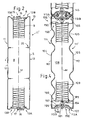
- Fig. 1 shows a total of 1 designated noise barrier, which is formed of a plurality of noise protection elements 10, which are arranged one above the other in horizontal construction.
- the noise protection elements 10 are each attached at their ends in posts 2 with I-profile, which are anchored in a ground foundation 3.
- the noise protection elements 10 each consist of elongated, self-supporting and composite to a hollow box profile Streispreßprofilblechen, wherein one of the large-scale wall sides of each noise protection element 10 forms a front wall 4 and the noise source, such as the rails of a high-speed track, facing, while the side facing away from the noise protection source the rear wall. 5 forms.
- Both the front and the rear wall 4.5 may be provided with a hole pattern for sound refraction, as is known in principle in the prior art.
- Each noise protection element 10 consists of two identically constructed, produced as extruded profiles of a suitable aluminum alloy, half-shell-shaped profile sheets 11, 11 'each having a large area wall surface 12 which forms the front wall 4 and the rear wall 5 of the noise protection element 10 according to the orientation of the noise protection element ,
- the left wall surface 12 is referred to as the front wall 4
- the right wall surface 12 is referred to as the rear wall 5.
- the rear wall and the front wall could each also be formed by the other wall surface.
- the sound-absorbing body 9, the front wall 4 and the rear wall 5 are arranged symmetrically to the center plane M of the noise protection element 10.
- the front wall 4 and rear wall 5 forming wall surfaces 12 of both profile sheets 11, 11 'go on the side edges in one piece with a generally designated 13A and 13B, in the prototyping of the profile sheets already formed section over, with both sections 13A, 13B each to extend to the median plane M.
- Both the half-shell-shaped profile sheet 11 and the half-shell-shaped profile sheet 11 ' is each at a side edge with a Part section 13A and provided at the other side edge with a portion 13B, which are connected to one another at the level of the median plane M positively by a total of 15 designated profile connection.
- Each of the upper and the lower side wall 6, 7 is thus formed approximately halfway from the one section 13A and the other half from the other section 13B.
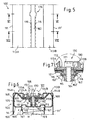
- the profile connection 15 in this case comprises on the one hand a profile section 16 at the free end of the section 13A as a first joining element, which engages in a form the second joining element hollow chamber groove 17 which is surrounded by the wall 18 which is formed at the free end of the section 13B, positively engages.
- the block-shaped profile section 16 is in this case integrally formed on the extension of an intermediate leg 19A of the subsection 13A and the wall 18, which surrounds the hollow chamber groove 17, at the free end of an intermediate leg 19B of the subsection 13B.
- the profile section 16 extends substantially symmetrically to both sides of the median plane M and the hollow chamber groove 17 is also formed symmetrically around the region of the median plane M around.
- the profile connection 15 between the profiled sheets 11, 11 'and the subsections 13A, 13B is achieved by inserting the profile section 16 into the hollow chamber groove 17 and a longitudinal displacement of the two profile sheets 11, 11' to each other, which are rotated by 180 ° against each other, before they are pushed together.
- the profile section 16 is integrally connected via a leg extension 20 with the intermediate leg 19A of the section 13A and integrally formed on the intermediate leg 19B
- Wall 18 for the hollow chamber groove 17 has in the axial extension of the intermediate leg 19B an opening 21 through which the leg extension 20 engages.
- the hollow chamber groove 17 extends relative to the opening 21 both upwards and downwards, so that the wall 18 of the section 13 B with the two boundary legs 22 and 23 of the opening 21 on the profiled sheet 11 an undercut for the profile section 16 on the portion 13 A of the other profile sheet 11 'forms.
- Both the profile section 16 and the hollow chamber groove 17 have a rectangular cross section in the embodiment shown.
- intermediate legs 19A and 19B of both profile sheets 11, 11 ' are relative to support legs 14A and 14B, which extend at right angles to the wall surfaces 12 and directly adjoin the side edges of the front and rear walls 4, 5, in the cavity 8 set back by means of the intermediate legs 24A and 24B, so that the upper and lower side walls 6, 7 of two superposed noise protection elements 10 rest only in the region of the support legs 14A, 14B and in the region of an outer leg 25 of the wall 18 of the hollow chamber groove 17.
- Both intermediate legs 19A, 19B are, immediately following the offset legs 24A and 24B, provided with a T-shaped receiving groove 27, which are delimited by two integrally formed on the extrusion metal sheets 11 L-shaped legs 28, 29.
- the receiving groove 27 and the L-shaped legs 28, 29 are each formed profile inside, so that they are in the noise protection elements 10 in the cavity 8.
- support strips 40 are inserted to support the sound absorbing body 9 laterally.
- intermediate leg 19A is further provided with two integrally and externally formed on this angle webs 30, 31, with which a T-shaped receiving chamber 32 is limited, in which a Sp Drichtungsance 45 can be inserted, which assumes an additional sound insulation between the side walls 6, 7 of the noise protection elements 10.
- the angle web 31 is so formed on the intermediate leg 19A that it rests in the assembled state with one of its leg portions parallel to the web portion 23 of the wall 18 for the hollow chamber groove 17 to fix the profile connection 15 in the longitudinal direction of the noise protection elements by contact friction.
- 2 and 3 is not shown that the profile connection 15 in the noise protection element 10 according to the first embodiment can be secured in addition to the form-fitting still by one or more locking means, which are also aligned with the neutral fiber of the noise protection element, hence here the median plane M, are arranged.
- the locking means may consist in particular of a plug-in or screw connection, which, for example, the outer leg of the wall 18 of the hollow chamber groove 17 extends and is screwed or inserted into the profile section 16. With the locking means then an unillustrated end cover can be attached immediately, which closes the cavity of the profiled sheets 11, 11 'formed hollow box profile also the front side.
- both profile sheets 11, 11 'of each noise protection element 10 are, as shown in FIG. 2, provided with a plurality of urgeformten during extrusion of the profile sheets 11 stabilizing webs 35, which extend over the entire length of the noise protection elements 10 with a constant cross-section and essentially a Have a Y-shaped contour.
- both profiled sheets 11, 11 ' are provided with two stabilizing webs 35 each offset by 1/3 of the total height. It is understood that, depending on the expected dynamic loads further stabilizing webs 35 could possibly also be provided with different geometries for the longitudinal grooves and the web extensions.
- the noise protection elements have on both sides of the profile connection 15 and laterally and below the inner leg 34 each have a channel 38, 39, wherein the channel 38 between the leg 28 and the vertical web of the wall 18 and the second channel 39 between the boundary leg 22 and the leg 28 is formed, while the sound-absorbing body is supported on the support strips 40 and the inner leg 34.
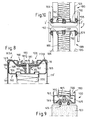
- Figures 4 to 10 show a second embodiment according to the invention for a noise protection element 100.
- the noise protection element 100 consists of two identically shaped, produced as extruded from a suitable aluminum alloy, half-shell-shaped profile sheets 111, 111 ', which in turn each have a large-area wall surface 112, the according to the orientation of the noise protection element 100, as indicated in Fig. 4, the front wall 104 and rear wall 105 form.
- the front wall ie the noise source such as the tracks facing profiled sheet 111 may be executed perforated, wherein the hole surface portion based on the entire surface of the front wall 104 may make up about 27%.
- the rear wall 105 of the noise protection elements 100 is preferably unperforated.
- Figures 6 to 8 each show a vertical section through the noise protection elements 100 in the region of the upper side wall 106 and the connecting profile body 160.
- the connecting profile body 160 For the positive connection of the two profile sheets 111, 111 'of the connecting profile body 160 on its side wall 106 facing and adjacent to the inside front sides 161 provided with a groove 162.
- Both profiled half-shells 111, 111 ' are positively fixed and positively connected to one another at this groove 162.
- Both profiled sheets 111, 111' merge integrally into subsections 113A, 113B on both side walls 106, 107, each of the subsections 113A, 113B first adjacent to the vertically extending front and rear wall, aligned at right angles to these support legs 114A, 114B, which in turn via an inwardly bent offset legs 124A and 124B in a perpendicular to the side walls and parallel to the support legs 114A, 114B extending intermediate leg 119A 119B, at the ends of which inwardly angled edges 116 or edge webs are formed. Both edges 116 on both intermediate limbs 119A, 119B, as shown particularly clearly in FIG.
- the connecting profile bodies 160 are made of extruded aluminum extruded profile bodies and comprise a comparatively strongly dimensioned, solid material cross-sectioned central web 164 which is arranged on the median plane M of the noise protection element 100 and forms the bottom of the groove 162.
- the connecting profile body 160 extends on both sides of the central web 164 with a hollow chamber portion 165, wherein a bottom wall 166 of each hollow chamber portion 165 at right angles projecting support webs 167 for lateral support of the insulating board 109, the side chamber side walls 168 inside the profile plates 111 and 111 'abut and the front wall 161, which adjoins the side wall 106, has angled sections with a chamber offset leg 169 in accordance with the shape of the side wall 106.
- the connecting profile body 160 thus lies in the region of the upper and lower ends of the noise protection elements 100 positively against the profile sheets 111, 111 ', whereby an additional stiffening of the noise protection element 100 is achieved.
- the comparatively wide, made of solid material central web 164 of the connecting profile body 160 is dimensioned such that locking screws 171 and 181 can be screwed into the central web 164 and anchored there. With the locking screws 171 and 181, which each include a plate 172 or 182 or clamping ring below the screw head, a bar 190 is fixed in each case in the mounting state within the recess on the legs 124A, 124B and 119A, 119B caused depression in both side walls 106, 107 is located.
- Both subsections 113A, 113B, which together form the upper and lower side wall 106, 107 of each noise protection element 100, are thus locked both by positive engagement and by clamping, with both the clamping and the positive connection in particular to the region of the median plane M and to focus on the area of least dynamic loads.
- FIG. 8 shows an alternative embodiment for a locking means 180, in which the clamping is achieved exclusively via the clamping forces between the strip 190 and the connecting profile body 160.
- the clamping screw 181 lies with its clamping plate in a groove recess in the bar 190, passes through the groove 162 in the connecting profile body 160 and is screwed with its threaded portion in the central web 164.
- Figures 6 and 7 show a particularly preferred embodiment for additional clamping and locking of the two profile sheets 111, 111 'in the profile connection 115 with the connecting profile body 160.
- the locking means 170 shown in Figures 6 and 7 comprises a clamping sleeve 175 made of stainless steel which is arranged in the groove 162.
- Fig. 5 it is illustrated that the groove 162 in the region in which the locking means 170 are arranged with the clamping sleeves 175, a widening or widening 176 of the groove 162 is formed.
- the widening 176 of the groove 162 can be achieved, in particular, by a countersinking or countersinking, wherein this countersinking is formed in the connecting profiled bodies before they are inside the noise protection elements 100 for the positive connection of the two profile sheets 111, 111 'are inserted.
- the clamping sleeve 175 is dimensioned such that its outer circumference substantially equal to the diameter of the reduction 176 reduced by twice the wall thickness of the profile sheets 111, 111 'corresponds.
- each receptacle 195 comprises an outwardly facing, in cross-section schbrund grooved groove 196, to which the O-shaped portion of the sealant 145 may abut, and a channel 197 open to the bottom of the groove 196, in which the sealant 145 is formed by means of an integrally formed T-shaped O-shaped portion Section or the like. can be anchored.
- FIGS. 4 and 9 further show that the connecting profile body 160 in the region of the two profile chambers 165 from each other and serving to lock the locking means 170 and 180 serving middle web 164 are provided near or adjacent to the bottom 166 with a keyhole-like profile recess 185.
- This profile recess 185 serves to be able to fasten a front cover 150 to the two vertically extending end faces of each noise protection element 100 in a simple manner, as shown in FIG.
- the fastening screw 151 shown schematically in FIG. 10 for fastening the end cover 150 reaches through the latter and then grips into the keyhole recess 185 of the central web 164.
- the end cover 150 is provided with hook projections 152 which position and support the insulation board 109 also frontally.
- the front side covers 150 comprise cover edges 153 which bear on the outside of the profiled sheets or the front wall 104 and rear wall 105 and which are provided with further receptacles for suitable sealing means 155 which are in the assembled state of a noise protection wall between the profile webs 2 'of the I-profile posts 2 and the front and rear walls 104, 105 are arranged in the region of the front ends of the noise protection elements 100 in order to prevent the occurrence of vibrations. All sealants may consist of EPDM gaskets or other suitable gaskets.
- the profiled sheets 111, 111 ' can be provided with suitable longitudinal profilings, such as the longitudinal profilings 135 shown in FIG. 4, in order to achieve additional stiffening.
- the neutral fiber does not necessarily coincide with the midplane.
- the two sections also joining elements with other cross-sections such. dovetail-shaped joining elements or the like.
- the sound-absorbing body may be made of any suitable materials, wherein in the same hollow box profile by the use of other support strips and sound insulation can be used with other thicknesses.
- In the cavity of the noise protection and sound insulation body can be arranged, which have two highly absorbent Dämmwollplatten, which on either side of a centrally located on the median plane of the noise protection element wood fiber cement board or the like. are located.
- the noise protection elements and noise protection walls designed according to the invention can be used, in particular, on railway lines for high-speed trains, on runways for aircraft and in other fields of application in which high, dynamic pressure and suction loads act on the noise protection elements and walls.
Landscapes
- Engineering & Computer Science (AREA)
- Architecture (AREA)
- Civil Engineering (AREA)
- Structural Engineering (AREA)
- Devices Affording Protection Of Roads Or Walls For Sound Insulation (AREA)
- Telephone Set Structure (AREA)
- Inorganic Insulating Materials (AREA)
- Burglar Alarm Systems (AREA)
- Building Environments (AREA)
Claims (20)
- Elément de protection contre le bruit pour ériger des parois de protection contre le bruit, comprenant un profilé en caisson présentant une paroi avant (4 ; 104), une paroi arrière (5 ; 105), une paroi latérale supérieure (6 ; 106) et une paroi latérale inférieure (7 ; 107), lequel est composé d'une première et d'une seconde tôle profilée en forme de demi-coque (11, 11' ; 111, 111') et dans la cavité (8 ; 108) duquel un corps d'isolation acoustique (9 ; 109) qui, de préférence, fait saillie depuis la paroi latérale inférieure vers la paroi latérale supérieure et s'étend au-delà de la longueur du profilé en caisson symétriquement par rapport au plan médian (M) entre la paroi avant (4 ; 104) et la paroi arrière (5 ; 105), est agencé ou peut être agencé, sachant que la première tôle profilée (11, 11') comporte en un seul tenant la paroi avant (4 ; 104), un tronçon partiel (13B ; 113B) de la paroi latérale inférieure (7 ; 107) et un tronçon partiel (13A ; 113A) de la paroi latérale supérieure (6 ; 106), sachant que la seconde tôle profilée (111, 111') comporte en un seul tenant la paroi arrière (5 ; 105), un tronçon partiel (13A ; 113A) de la paroi latérale inférieure (7 ; 107) et un tronçon partiel (13B ; 113B) de la paroi latérale supérieure (6 ; 106), et sachant que la première et la seconde tôle profilée (11, 11' ; 111, 111') sont reliées entre elles au niveau de la paroi latérale supérieure et de la paroi latérale inférieure (6, 7 ; 106, 107) respectivement à la hauteur du plan médian (M) par une liaison de profilés à coopération de formes (15 ; 115), caractérisé en ce que la liaison de profilés à coopération de formes (15 ; 115) est assurée à l'aide d'au moins un moyen de blocage supplémentaire (170, 180), sachant que la liaison de profilés (15 ; 115) et les moyens de blocage (170, 180) sont agencés à la hauteur du plan médian de l'élément de protection contre le bruit, par conséquent dans une zone qui forme une fibre neutre ou un plan neutre de l'élément de protection contre le bruit en ce qui concerne la flexion dynamique et la torsion dynamique.
- Elément de protection contre le bruit selon la revendication 1, caractérisé en ce que les deux tôles profilées (11, 11' ; 111, 111') sont des profilés de filage, sachant que les tôles profilées sont constituées de préférence d'un alliage d'aluminium, en particulier d'un alliage d'aluminium pouvant être sollicité par de hautes vibrations.
- Elément de protection contre le bruit selon l'une ou l'autre des revendications 1 et 2, caractérisé en ce que les deux tôles profilées (11, 11' ; 111, 111') présentent une forme profilée identique.
- Elément de protection contre le bruit selon l'une des revendications 1 à 3, caractérisé en ce que les moyens de blocage (170, 180) sont agencés à la hauteur du plan médian (M) et comportent un moyen à visser (171, 181).
- Elément de protection contre le bruit selon l'une des revendications 1 à 4, caractérisé en ce que chaque tôle profilée (11 ; 11') présente un premier élément d'assemblage (16) sur le un tronçon partiel (13A) et un second élément d'assemblage (17) sur l'autre tronçon partiel (13B), sachant que, de préférence, le premier élément d'assemblage pour la liaison de profilés (15) est constitué d'une gorge faisant cavité (17) avec contre-dépouille et sachant que le second élément d'assemblage est constitué d'un tronçon profilé (16) pouvant être ancré dans celle-ci par coopération de formes.
- Elément de protection contre le bruit selon la revendication 5, caractérisé en ce que le tronçon profilé (16) et la gorge faisant cavité (17) sont réalisés avec une forme rectangulaire, sachant que, de préférence, le tronçon profilé (16) a un profilé en bloc et sachant que la gorge faisant cavité (17) ou sa paroi (18) a un profilé à quatre pans.
- Elément de protection contre le bruit selon l'une ou l'autre des revendications 5 et 6, caractérisé en ce que, pour chaque tôle profilée (11 ; 11'), le tronçon profilé (16) forme l'extrémité du tronçon partiel (13A) pour la une paroi latérale (6 ; 7) et en ce que la gorge faisant cavité (17) ou sa paroi (18) forme l'extrémité du tronçon partiel (13B) pour l'autre paroi latérale (7 ; 6).
- Elément de protection contre le bruit selon la revendication 4, ou selon la revendication 4 et selon l'une des revendications 5 à 7, caractérisé en ce que le moyen à visser s'engage dans des perçages réalisés en alignement l'un par rapport à l'autre et réalisés dans les deux éléments d'assemblage, en particulier en ce qu'il s'engage dans des perçages qui pénètrent au moins partiellement dans la gorge faisant cavité (17) ou dans sa paroi (18) et dans le tronçon profilé (16).
- Elément de protection contre le bruit selon l'une des revendications 6 à 8, caractérisé en ce qu'une branche d'appui (14A ; 14B) s'étendant perpendiculairement aux bords latéraux de la paroi avant et de la paroi arrière (4, 5) vient se raccorder à ceux-ci, laquelle se transforme par l'intermédiaire d'une branche pliée vers l'intérieur et faisant retrait (24A ; 24B) en une branche intermédiaire (19A, 19B) sur l'extrémité de laquelle sont réalisés les éléments d'assemblage, en particulier le tronçon profilé (16) ou le tronçon à cavité (17) ou sa paroi (18).
- Elément de protection contre le bruit selon l'une des revendications 1 à 4, caractérisé en ce que la liaison de profilés (115) comporte sur les deux parois latérales (106, 107) un corps profilé de liaison (160) agencé dans la cavité (108), lequel est muni d'une rainure (162) qui, dans l'état de montage, est tournée vers la paroi latérale adjacente et sur laquelle les tronçons partiels (113A ; 113B) des parois latérales (106, 107) sont fixés par coopération de formes et sont assurés à l'aide des moyens de blocage (170, 180).
- Elément de protection contre le bruit selon la revendication 10, caractérisé en ce que les tronçons partiels sont coincés en partie contre le corps profilé de liaison (160) avec les moyens de blocage (170, 180, 190) et en ce que la liaison de profilés (115) est assurée en supplément par coincement.
- Elément de protection contre le bruit selon l'une ou l'autre des revendications 10 et 11, caractérisé en ce que les corps profilés de liaison (160) sont constitués de corps profilés de filage extrudés, de préférence en aluminium.
- Elément de protection contre le bruit selon l'une des revendications 10 à 12, caractérisé en ce que chaque corps profilé de liaison (160) présente un montant médian (164) agencé sur le plan médian (M) et formant le fond de la rainure (162), dans lequel les moyens d'ancrage (170, 180) sont ancrés ou peuvent être ancrés, sachant que, de préférence, le corps profilé de liaison (160) présente respectivement vers deux côtés du montant médian (164) un tronçon faisant cavité (165) qui arrive jusque vers la paroi avant (104) et la paroi arrière (107).
- Elément de protection contre le bruit selon l'une des revendications 10 à 13, caractérisé en ce que les tronçons partiels (113A, 113B) des parois latérales présentent sur leurs extrémités des montants à arête (116) coudés de préférence perpendiculairement, lesquels s'enchâssent jusque dans la rainure (162), sachant que, de préférence, une branche d'appui (114A, 114B) s'étendant perpendiculairement aux bords latéraux de la paroi avant et de la paroi arrière vient se raccorder à ceux-ci, laquelle se transforme par l'intermédiaire d'une branche faisant retrait et pliée vers l'intérieur (124A, 124B) en une branche intermédiaire (119A, 119B) sur les extrémités de laquelle sont réalisés les arêtes pliées (116).
- Elément de protection contre le bruit selon la revendication 14, caractérisé en ce que des douilles de blocage (175) sont attribuées au moins à quelques uns des moyens de blocage (170), lesquelles coincent les montants à arête (116) contre les flancs latéraux de rainure (162'), sachant que, de préférence, la rainure (162) est munie de renfoncements ou d'élargissements (176) dans lesquels s'engagent les douilles de blocage (175) par coopération de formes.
- Elément de protection contre le bruit selon l'une des revendications 10 à 15, caractérisé en ce que les corps profilés de liaison (160) sont munis intégralement de montants d'appui (167) sur leurs côtés inférieurs détournés des rainures (162) pour le positionnement et le soutien latéral du corps d'isolation acoustique (109).
- Elément de protection contre le bruit selon l'une des revendications 14 et 15 ou 16, caractérisé en ce que le montant médian (164) du corps profilé de liaison (160) est muni d'un évidement profilé à la manière d'un trou de clé qui est adjacent à son côté inférieur.
- Elément de protection contre le bruit selon l'une des revendications 10 à 17, caractérisé en ce que des listeaux (190) sont fixés sur les parois latérales (106, 107) avec les moyens de blocage (170, 180), lesquels sont munis de logements (195) pour des éléments d'étanchement (145), sachant que, de préférence, les logements (195) présentent une cannelure excavée (196) montrant vers l'extérieur et à section transversale demi-ronde comme tronçon de contact pour l'élément d'étanchement (145) et un canal (197) réalisé avec une contre-dépouille et ouvert vers le sommet du fond de la cannelure (196) comme tronçon d'ancrage pour l'élément d'étanchement (145).
- Paroi de protection contre le bruit pour des tronçons de voies ferrées, en particulier des trains à haute vitesse ou d'autres domaines d'application sujets à des sollicitations alternantes d'aspiration et de pression, caractérisée en ce que la paroi de protection contre le bruit (1) est formée d'éléments de protection contre le bruit (10 ; 100) agencés l'un au-dessus de l'autre selon l'une des revendications 1 à 18.
- Paroi de protection contre le bruit selon la revendication 19, caractérisée en ce que les éléments de protection contre le bruit sont fixés sur la face frontale sur des poteaux (2) avec un profilé en I, sachant qu'un palier en caoutchouc ou un élément d'étanchement (155) est agencé entre les éléments de protection contre le bruit (10 ; 100) et le poteau (2) pour l'amortissement des oscillations et/ou que l'élément de protection contre le bruit inférieur (100) s'appuie sur un socle en béton (103), et sachant qu'au moins un élément d'étanchement (145) ancré de préférence dans le listeau (190) est agencé entre la paroi latérale inférieure (107) de l'élément de protection contre le bruit et le socle en béton (103).
Priority Applications (1)
| Application Number | Priority Date | Filing Date | Title |
|---|---|---|---|
| RU2005112867/22U RU49834U1 (ru) | 2004-11-04 | 2005-04-27 | Шумозащитный элемент и шумозащитный экран |
Applications Claiming Priority (2)
| Application Number | Priority Date | Filing Date | Title |
|---|---|---|---|
| DE20317180U DE20317180U1 (de) | 2003-11-04 | 2003-11-04 | Lärmschutzelement und Lärmschutzwand |
| DE20317180U | 2003-11-04 |
Publications (2)
| Publication Number | Publication Date |
|---|---|
| EP1529883A1 EP1529883A1 (fr) | 2005-05-11 |
| EP1529883B1 true EP1529883B1 (fr) | 2007-12-12 |
Family
ID=34042350
Family Applications (1)
| Application Number | Title | Priority Date | Filing Date |
|---|---|---|---|
| EP04026119A Expired - Lifetime EP1529883B1 (fr) | 2003-11-04 | 2004-11-04 | Mur anti-bruit |
Country Status (3)
| Country | Link |
|---|---|
| EP (1) | EP1529883B1 (fr) |
| AT (1) | ATE380901T1 (fr) |
| DE (2) | DE20317180U1 (fr) |
Families Citing this family (6)
| Publication number | Priority date | Publication date | Assignee | Title |
|---|---|---|---|---|
| DE202006001472U1 (de) * | 2006-01-30 | 2007-06-06 | Lublow, Felix | Aluminium-Lärmschutzwand-System für Verkehrswege mit neuartiger Schalldämmung für bestimmte Frequenzen |
| AT504518B1 (de) * | 2006-12-22 | 2008-06-15 | Brunbauer Wolfgang Dipl Ing | Aufbau, vorzugsweise zur schalldämmenden begrenzung von verkehrswegen |
| AT507004B1 (de) * | 2008-06-27 | 2010-11-15 | Brunbauer Wolfgang Dipl Ing | Lärmschutzwand |
| RU2405082C1 (ru) * | 2009-06-15 | 2010-11-27 | Открытое Акционерное Общество "Российские Железные Дороги" | Способ изготовления шумозащитного экрана |
| CN114516105B (zh) * | 2020-11-20 | 2025-07-22 | 江苏瑞达康环保科技发展有限公司 | 一种声屏障金属陶粒吸声板的生产工艺 |
| DE102023111161A1 (de) * | 2023-04-28 | 2024-10-31 | R. Kohlhauer Gmbh | Lärmschutzelement und Lärmschutzwand |
Family Cites Families (5)
| Publication number | Priority date | Publication date | Assignee | Title |
|---|---|---|---|---|
| DE2929853C2 (de) * | 1979-07-24 | 1985-05-02 | Rheinhold & Mahla GmbH, 8000 München | Lärmschutzwand |
| CH672932A5 (en) * | 1987-07-28 | 1990-01-15 | Montana Stahl Ag | Noise-attenuating wall section - contains insulating layers of different densities, with first layer held clear of front wall by distance piece |
| DE29609237U1 (de) * | 1996-05-23 | 1996-08-14 | Koch GmbH & Co. KG, 56412 Nentershausen | Wandelement zur Errichtung von Schutzwänden |
| IT1286776B1 (it) * | 1996-11-19 | 1998-07-17 | Fracasso Metalmeccanica | Pannello antiacustico |
| NL1009264C2 (nl) * | 1998-05-26 | 1999-11-29 | Mostert De Winter B V | Geluidswerende wand voor opstelling langs een spoorbaan of verkeersweg. |
-
2003
- 2003-11-04 DE DE20317180U patent/DE20317180U1/de not_active Expired - Lifetime
-
2004
- 2004-11-04 EP EP04026119A patent/EP1529883B1/fr not_active Expired - Lifetime
- 2004-11-04 DE DE502004005691T patent/DE502004005691D1/de not_active Expired - Lifetime
- 2004-11-04 AT AT04026119T patent/ATE380901T1/de not_active IP Right Cessation
Also Published As
| Publication number | Publication date |
|---|---|
| DE502004005691D1 (de) | 2008-01-24 |
| ATE380901T1 (de) | 2007-12-15 |
| DE20317180U1 (de) | 2005-01-05 |
| EP1529883A1 (fr) | 2005-05-11 |
Similar Documents
| Publication | Publication Date | Title |
|---|---|---|
| DE4226742A1 (de) | Verkleidungselement für Böden, Decken, Wände und Fassaden | |
| WO1998020203A1 (fr) | Fondation de voie ferree | |
| EP2210978A2 (fr) | Mini-mur de protection pour rails de voies | |
| EP2817457B1 (fr) | Dispositif anti-bruit | |
| EP1529883B1 (fr) | Mur anti-bruit | |
| EP0219811B1 (fr) | Construction de support de rails | |
| EP2126218B1 (fr) | Absorbeur de bruit avec profilés de support | |
| EP1114221B1 (fr) | Structure de traverses destinee a une voie ferree destinee a des vehicules ferroviaires, notamment a une voie ballastee | |
| EP1659222B1 (fr) | Élément antibruit, mur antibruit et procédé pour la production de l'élément antibruit | |
| DE9113416U1 (de) | Lärmschutzwand | |
| DE4016164A1 (de) | Befestigungskonsole fuer ein fassadenbefestigungssystem | |
| DE8336223U1 (de) | Schallisolierende wand | |
| DE19920146B4 (de) | Lagerung einer Schiene für Schienenfahrzeuge | |
| EP0603517A1 (fr) | Maçonnerie pour linteau avec armature et dispositif de suspension relatif | |
| EP1072726B1 (fr) | Mur antibruit le long d'un chemin | |
| AT337426B (de) | Anordnung zum verbinden von plattenelementen | |
| EP2045394A1 (fr) | Zone de croisement de rails à gorge | |
| EP2034100A2 (fr) | Plaque à trou en plâtre et procédé de fabrication d'une couverture suspendue | |
| DE29905550U1 (de) | Absorptionsbelag zur Reduzierung der Schallabstrahlung für Gleiskörper | |
| DE9106804U1 (de) | Lärmschutzelement zur Bildung von Lärmschutzwänden | |
| DE10320003A1 (de) | Positioniervorrichtung, Schalungseinheit und Wandschalung | |
| DE19920075A1 (de) | Lagerung einer Schiene für Schienenfahrzeuge | |
| AT15964U1 (de) | Installationsblock | |
| DE2058167C3 (de) | Vorrichtung zum Abstützen von die äußere Schale eines zweischaligen Flachdaches bildenden Dacheindeckungsplatten | |
| CH683359A5 (de) | Schallschutzelement. |
Legal Events
| Date | Code | Title | Description |
|---|---|---|---|
| PUAI | Public reference made under article 153(3) epc to a published international application that has entered the european phase |
Free format text: ORIGINAL CODE: 0009012 |
|
| AK | Designated contracting states |
Kind code of ref document: A1 Designated state(s): AT BE BG CH CY CZ DE DK EE ES FI FR GB GR HU IE IS IT LI LU MC NL PL PT RO SE SI SK TR |
|
| AX | Request for extension of the european patent |
Extension state: AL HR LT LV MK YU |
|
| 17P | Request for examination filed |
Effective date: 20050503 |
|
| 17Q | First examination report despatched |
Effective date: 20050608 |
|
| AKX | Designation fees paid |
Designated state(s): AT BE BG CH CY CZ DE DK EE ES FI FR GB GR HU IE IS IT LI LU MC NL PL PT RO SE SI SK TR |
|
| AXX | Extension fees paid |
Extension state: LV Payment date: 20050503 Extension state: LT Payment date: 20050503 Extension state: HR Payment date: 20050503 |
|
| GRAP | Despatch of communication of intention to grant a patent |
Free format text: ORIGINAL CODE: EPIDOSNIGR1 |
|
| GRAS | Grant fee paid |
Free format text: ORIGINAL CODE: EPIDOSNIGR3 |
|
| GRAA | (expected) grant |
Free format text: ORIGINAL CODE: 0009210 |
|
| AK | Designated contracting states |
Kind code of ref document: B1 Designated state(s): AT BE BG CH CY CZ DE DK EE ES FI FR GB GR HU IE IS IT LI LU MC NL PL PT RO SE SI SK TR |
|
| AX | Request for extension of the european patent |
Extension state: HR LT LV |
|
| REG | Reference to a national code |
Ref country code: GB Ref legal event code: FG4D Free format text: NOT ENGLISH |
|
| REG | Reference to a national code |
Ref country code: CH Ref legal event code: EP |
|
| REG | Reference to a national code |
Ref country code: IE Ref legal event code: FG4D Free format text: LANGUAGE OF EP DOCUMENT: GERMAN |
|
| REF | Corresponds to: |
Ref document number: 502004005691 Country of ref document: DE Date of ref document: 20080124 Kind code of ref document: P |
|
| PG25 | Lapsed in a contracting state [announced via postgrant information from national office to epo] |
Ref country code: SE Free format text: LAPSE BECAUSE OF FAILURE TO SUBMIT A TRANSLATION OF THE DESCRIPTION OR TO PAY THE FEE WITHIN THE PRESCRIBED TIME-LIMIT Effective date: 20080312 |
|
| LTIE | Lt: invalidation of european patent or patent extension |
Effective date: 20071212 |
|
| PG25 | Lapsed in a contracting state [announced via postgrant information from national office to epo] |
Ref country code: SI Free format text: LAPSE BECAUSE OF FAILURE TO SUBMIT A TRANSLATION OF THE DESCRIPTION OR TO PAY THE FEE WITHIN THE PRESCRIBED TIME-LIMIT Effective date: 20071212 Ref country code: PL Free format text: LAPSE BECAUSE OF FAILURE TO SUBMIT A TRANSLATION OF THE DESCRIPTION OR TO PAY THE FEE WITHIN THE PRESCRIBED TIME-LIMIT Effective date: 20071212 Ref country code: FI Free format text: LAPSE BECAUSE OF FAILURE TO SUBMIT A TRANSLATION OF THE DESCRIPTION OR TO PAY THE FEE WITHIN THE PRESCRIBED TIME-LIMIT Effective date: 20071212 Ref country code: NL Free format text: LAPSE BECAUSE OF FAILURE TO SUBMIT A TRANSLATION OF THE DESCRIPTION OR TO PAY THE FEE WITHIN THE PRESCRIBED TIME-LIMIT Effective date: 20071212 |
|
| NLV1 | Nl: lapsed or annulled due to failure to fulfill the requirements of art. 29p and 29m of the patents act | ||
| GBV | Gb: ep patent (uk) treated as always having been void in accordance with gb section 77(7)/1977 [no translation filed] | ||
| PG25 | Lapsed in a contracting state [announced via postgrant information from national office to epo] |
Ref country code: IS Free format text: LAPSE BECAUSE OF FAILURE TO SUBMIT A TRANSLATION OF THE DESCRIPTION OR TO PAY THE FEE WITHIN THE PRESCRIBED TIME-LIMIT Effective date: 20080412 Ref country code: ES Free format text: LAPSE BECAUSE OF FAILURE TO SUBMIT A TRANSLATION OF THE DESCRIPTION OR TO PAY THE FEE WITHIN THE PRESCRIBED TIME-LIMIT Effective date: 20080323 Ref country code: CZ Free format text: LAPSE BECAUSE OF FAILURE TO SUBMIT A TRANSLATION OF THE DESCRIPTION OR TO PAY THE FEE WITHIN THE PRESCRIBED TIME-LIMIT Effective date: 20071212 |
|
| PG25 | Lapsed in a contracting state [announced via postgrant information from national office to epo] |
Ref country code: RO Free format text: LAPSE BECAUSE OF FAILURE TO SUBMIT A TRANSLATION OF THE DESCRIPTION OR TO PAY THE FEE WITHIN THE PRESCRIBED TIME-LIMIT Effective date: 20071212 Ref country code: SK Free format text: LAPSE BECAUSE OF FAILURE TO SUBMIT A TRANSLATION OF THE DESCRIPTION OR TO PAY THE FEE WITHIN THE PRESCRIBED TIME-LIMIT Effective date: 20071212 |
|
| EN | Fr: translation not filed | ||
| PG25 | Lapsed in a contracting state [announced via postgrant information from national office to epo] |
Ref country code: PT Free format text: LAPSE BECAUSE OF FAILURE TO SUBMIT A TRANSLATION OF THE DESCRIPTION OR TO PAY THE FEE WITHIN THE PRESCRIBED TIME-LIMIT Effective date: 20080512 |
|
| REG | Reference to a national code |
Ref country code: IE Ref legal event code: FD4D |
|
| PLBE | No opposition filed within time limit |
Free format text: ORIGINAL CODE: 0009261 |
|
| STAA | Information on the status of an ep patent application or granted ep patent |
Free format text: STATUS: NO OPPOSITION FILED WITHIN TIME LIMIT |
|
| PG25 | Lapsed in a contracting state [announced via postgrant information from national office to epo] |
Ref country code: IE Free format text: LAPSE BECAUSE OF FAILURE TO SUBMIT A TRANSLATION OF THE DESCRIPTION OR TO PAY THE FEE WITHIN THE PRESCRIBED TIME-LIMIT Effective date: 20071212 Ref country code: FR Free format text: LAPSE BECAUSE OF FAILURE TO SUBMIT A TRANSLATION OF THE DESCRIPTION OR TO PAY THE FEE WITHIN THE PRESCRIBED TIME-LIMIT Effective date: 20080926 Ref country code: DK Free format text: LAPSE BECAUSE OF FAILURE TO SUBMIT A TRANSLATION OF THE DESCRIPTION OR TO PAY THE FEE WITHIN THE PRESCRIBED TIME-LIMIT Effective date: 20071212 |
|
| 26N | No opposition filed |
Effective date: 20080915 |
|
| PG25 | Lapsed in a contracting state [announced via postgrant information from national office to epo] |
Ref country code: GB Free format text: LAPSE BECAUSE OF FAILURE TO SUBMIT A TRANSLATION OF THE DESCRIPTION OR TO PAY THE FEE WITHIN THE PRESCRIBED TIME-LIMIT Effective date: 20071212 |
|
| PG25 | Lapsed in a contracting state [announced via postgrant information from national office to epo] |
Ref country code: GR Free format text: LAPSE BECAUSE OF FAILURE TO SUBMIT A TRANSLATION OF THE DESCRIPTION OR TO PAY THE FEE WITHIN THE PRESCRIBED TIME-LIMIT Effective date: 20080313 |
|
| PG25 | Lapsed in a contracting state [announced via postgrant information from national office to epo] |
Ref country code: EE Free format text: LAPSE BECAUSE OF FAILURE TO SUBMIT A TRANSLATION OF THE DESCRIPTION OR TO PAY THE FEE WITHIN THE PRESCRIBED TIME-LIMIT Effective date: 20071212 Ref country code: BG Free format text: LAPSE BECAUSE OF FAILURE TO SUBMIT A TRANSLATION OF THE DESCRIPTION OR TO PAY THE FEE WITHIN THE PRESCRIBED TIME-LIMIT Effective date: 20080312 |
|
| BERE | Be: lapsed |
Owner name: BONGARD G.M.B.H. & CO. KG Effective date: 20081130 |
|
| PG25 | Lapsed in a contracting state [announced via postgrant information from national office to epo] |
Ref country code: MC Free format text: LAPSE BECAUSE OF NON-PAYMENT OF DUE FEES Effective date: 20081130 |
|
| REG | Reference to a national code |
Ref country code: CH Ref legal event code: PL |
|
| PG25 | Lapsed in a contracting state [announced via postgrant information from national office to epo] |
Ref country code: CY Free format text: LAPSE BECAUSE OF FAILURE TO SUBMIT A TRANSLATION OF THE DESCRIPTION OR TO PAY THE FEE WITHIN THE PRESCRIBED TIME-LIMIT Effective date: 20071212 |
|
| PG25 | Lapsed in a contracting state [announced via postgrant information from national office to epo] |
Ref country code: BE Free format text: LAPSE BECAUSE OF NON-PAYMENT OF DUE FEES Effective date: 20081130 |
|
| PG25 | Lapsed in a contracting state [announced via postgrant information from national office to epo] |
Ref country code: LI Free format text: LAPSE BECAUSE OF NON-PAYMENT OF DUE FEES Effective date: 20081130 Ref country code: CH Free format text: LAPSE BECAUSE OF NON-PAYMENT OF DUE FEES Effective date: 20081130 |
|
| PG25 | Lapsed in a contracting state [announced via postgrant information from national office to epo] |
Ref country code: AT Free format text: LAPSE BECAUSE OF NON-PAYMENT OF DUE FEES Effective date: 20081104 |
|
| PG25 | Lapsed in a contracting state [announced via postgrant information from national office to epo] |
Ref country code: HU Free format text: LAPSE BECAUSE OF FAILURE TO SUBMIT A TRANSLATION OF THE DESCRIPTION OR TO PAY THE FEE WITHIN THE PRESCRIBED TIME-LIMIT Effective date: 20080613 Ref country code: LU Free format text: LAPSE BECAUSE OF NON-PAYMENT OF DUE FEES Effective date: 20081104 |
|
| PG25 | Lapsed in a contracting state [announced via postgrant information from national office to epo] |
Ref country code: TR Free format text: LAPSE BECAUSE OF FAILURE TO SUBMIT A TRANSLATION OF THE DESCRIPTION OR TO PAY THE FEE WITHIN THE PRESCRIBED TIME-LIMIT Effective date: 20071212 |
|
| PG25 | Lapsed in a contracting state [announced via postgrant information from national office to epo] |
Ref country code: IT Free format text: LAPSE BECAUSE OF NON-PAYMENT OF DUE FEES Effective date: 20081130 |
|
| PGFP | Annual fee paid to national office [announced via postgrant information from national office to epo] |
Ref country code: DE Payment date: 20120918 Year of fee payment: 9 |
|
| PG25 | Lapsed in a contracting state [announced via postgrant information from national office to epo] |
Ref country code: DE Free format text: LAPSE BECAUSE OF NON-PAYMENT OF DUE FEES Effective date: 20140603 |
|
| REG | Reference to a national code |
Ref country code: DE Ref legal event code: R119 Ref document number: 502004005691 Country of ref document: DE Effective date: 20140603 |