EP1529675B1 - Leistungsübertragungsvorrichtung und Verfahren zur aktiven Drehmomentsteuerung - Google Patents
Leistungsübertragungsvorrichtung und Verfahren zur aktiven Drehmomentsteuerung Download PDFInfo
- Publication number
- EP1529675B1 EP1529675B1 EP04026278.4A EP04026278A EP1529675B1 EP 1529675 B1 EP1529675 B1 EP 1529675B1 EP 04026278 A EP04026278 A EP 04026278A EP 1529675 B1 EP1529675 B1 EP 1529675B1
- Authority
- EP
- European Patent Office
- Prior art keywords
- torque
- clutch
- clutch actuator
- transfer
- shaft
- Prior art date
- Legal status (The legal status is an assumption and is not a legal conclusion. Google has not performed a legal analysis and makes no representation as to the accuracy of the status listed.)
- Expired - Lifetime
Links
- 230000005540 biological transmission Effects 0.000 title claims description 54
- 238000000034 method Methods 0.000 title claims description 9
- 230000007246 mechanism Effects 0.000 claims description 22
- 230000001276 controlling effect Effects 0.000 claims description 14
- 230000000875 corresponding effect Effects 0.000 claims description 6
- 230000008859 change Effects 0.000 claims description 3
- 230000002596 correlated effect Effects 0.000 claims description 3
- QTAZYNKIJHHMCG-UHFFFAOYSA-N 4-(2,3,5-trichloro-4-hydroxyphenyl)iminocyclohexa-2,5-dien-1-one Chemical compound ClC1=C(Cl)C(O)=C(Cl)C=C1N=C1C=CC(=O)C=C1 QTAZYNKIJHHMCG-UHFFFAOYSA-N 0.000 claims 5
- 238000011217 control strategy Methods 0.000 description 17
- 230000008878 coupling Effects 0.000 description 11
- 238000010168 coupling process Methods 0.000 description 11
- 238000005859 coupling reaction Methods 0.000 description 11
- 230000004044 response Effects 0.000 description 5
- 230000006870 function Effects 0.000 description 4
- 230000003044 adaptive effect Effects 0.000 description 3
- 230000008901 benefit Effects 0.000 description 2
- 238000005516 engineering process Methods 0.000 description 2
- 230000003278 mimic effect Effects 0.000 description 2
- 230000009471 action Effects 0.000 description 1
- 230000003466 anti-cipated effect Effects 0.000 description 1
- 238000010276 construction Methods 0.000 description 1
- 230000004069 differentiation Effects 0.000 description 1
- 230000000694 effects Effects 0.000 description 1
- 230000004048 modification Effects 0.000 description 1
- 238000012986 modification Methods 0.000 description 1
- 230000002035 prolonged effect Effects 0.000 description 1
- 230000009467 reduction Effects 0.000 description 1
Images


Classifications
-
- B—PERFORMING OPERATIONS; TRANSPORTING
- B60—VEHICLES IN GENERAL
- B60K—ARRANGEMENT OR MOUNTING OF PROPULSION UNITS OR OF TRANSMISSIONS IN VEHICLES; ARRANGEMENT OR MOUNTING OF PLURAL DIVERSE PRIME-MOVERS IN VEHICLES; AUXILIARY DRIVES FOR VEHICLES; INSTRUMENTATION OR DASHBOARDS FOR VEHICLES; ARRANGEMENTS IN CONNECTION WITH COOLING, AIR INTAKE, GAS EXHAUST OR FUEL SUPPLY OF PROPULSION UNITS IN VEHICLES
- B60K23/00—Arrangement or mounting of control devices for vehicle transmissions, or parts thereof, not otherwise provided for
- B60K23/08—Arrangement or mounting of control devices for vehicle transmissions, or parts thereof, not otherwise provided for for changing number of driven wheels, for switching from driving one axle to driving two or more axles
- B60K23/0808—Arrangement or mounting of control devices for vehicle transmissions, or parts thereof, not otherwise provided for for changing number of driven wheels, for switching from driving one axle to driving two or more axles for varying torque distribution between driven axles, e.g. by transfer clutch
-
- B—PERFORMING OPERATIONS; TRANSPORTING
- B60—VEHICLES IN GENERAL
- B60W—CONJOINT CONTROL OF VEHICLE SUB-UNITS OF DIFFERENT TYPE OR DIFFERENT FUNCTION; CONTROL SYSTEMS SPECIALLY ADAPTED FOR HYBRID VEHICLES; ROAD VEHICLE DRIVE CONTROL SYSTEMS FOR PURPOSES NOT RELATED TO THE CONTROL OF A PARTICULAR SUB-UNIT
- B60W2510/00—Input parameters relating to a particular sub-units
- B60W2510/06—Combustion engines, Gas turbines
- B60W2510/0657—Engine torque
-
- B—PERFORMING OPERATIONS; TRANSPORTING
- B60—VEHICLES IN GENERAL
- B60W—CONJOINT CONTROL OF VEHICLE SUB-UNITS OF DIFFERENT TYPE OR DIFFERENT FUNCTION; CONTROL SYSTEMS SPECIALLY ADAPTED FOR HYBRID VEHICLES; ROAD VEHICLE DRIVE CONTROL SYSTEMS FOR PURPOSES NOT RELATED TO THE CONTROL OF A PARTICULAR SUB-UNIT
- B60W2710/00—Output or target parameters relating to a particular sub-units
- B60W2710/02—Clutches
- B60W2710/027—Clutch torque
Definitions
- the present invention relates generally to power transfer systems for controlling the distribution of drive torque between the front and rear drivelines of a four-wheel drive vehicle. More particularly, the present invention is directed to a power transmission device having a torque transfer mechanism equipped with a friction clutch, a power-operated clutch actuator, and a control system employing an active torque control strategy for controlling actuation of the power-operated clutch actuator.
- a power transmission device is operably installed between the primary and secondary drivelines.
- Such power transmission devices are typically equipped with a torque transfer mechanism for selectively and/or automatically transferring drive torque from the primary driveline to the secondary driveline to establish a four-wheel drive mode of operation.
- the torque transfer mechanism may include a dog-type lock-up clutch that can be selectively engaged for rigidly coupling the secondary driveline to the primary driveline to establish a locked or "part-time" four-wheel drive mode.
- drive torque is only delivered to the primary driveline when the lock-up clutch is released for establishing a two-wheel drive mode.
- a modern trend in four-wheel drive motor vehicles is to equip the power transmission device with a transfer clutch in place of the lock-up clutch.
- the transfer clutch is operable for automatically directing drive torque to the secondary wheels, without any input or action on the part of the vehicle operator, when traction is lost at the primary wheels for establishing an "on-demand" four-wheel drive mode.
- the transfer clutch includes a multi-plate clutch assembly that is installed between the primary and secondary drivelines and a clutch actuator for generating a clutch engagement force that is applied to the multi-plate clutch assembly.
- the clutch actuator In passive-type transfer clutch applications, the clutch actuator generates the clutch engagement force in response to the magnitude of the speed difference between the primary and secondary wheels.
- the clutch actuator includes a power-operated device that is actuated in response to electric control signals sent from an electronic control unit (ECU).
- ECU electronice control unit
- the ECU receives input signals from speed sensors associated with the primary and secondary drivelines as well as from other vehicle sensors and generates the control signal based thereon.
- speed sensors associated with the primary and secondary drivelines as well as from other vehicle sensors and generates the control signal based thereon.
- a large number of on-demand power transmission devices have been developed with an electrically-controlled clutch actuator that can regulate the amount of drive torque transferred to the secondary driveline as a function of the value of the electrical control signal applied thereto.
- the transfer clutch employs an electromagnetic clutch as the power-operated clutch actuator.
- U.S. Patent No. 5,407,024 discloses an electromagnetic coil that is incrementally activated to control movement of a ball-ramp drive assembly for applying a clutch engagement force on the multi-plate clutch assembly.
- Japanese Laid-open Patent Application No. 62-18117 discloses a transfer clutch equipped with an electromagnetic actuator for directly controlling actuation of the multi-plate clutch pack assembly.
- the transfer clutch can employ an electric motor and a drive assembly as its power-operated clutch actuator.
- U.S. Patent No. 5,323,871 discloses an on-demand transfer case having a transfer clutch equipped with an electric motor that controls rotation of a sector plate which, in turn, controls pivotal movement of a lever arm that is operable for applying the clutch engagement force to the multi-plate clutch assembly.
- Japanese Laid-open Patent Application No. 63-66927 discloses a transfer clutch which uses an electric motor to rotate one cam plate of a ball-ramp operator for engaging the multi-plate clutch assembly.
- 4,895,236 and 5,423,235 respectively disclose a transfer case equipped with a transfer clutch having an electric motor driving a reduction gearset for controlling movement of a ball screw operator and a ball-ramp operator which, in turn, apply the clutch engagement force to the clutch pack.
- full-time power transmission devices typically operate in the two-wheel drive mode and are adaptively shifted into the four-wheel drive mode in response to lost traction at the primary wheels.
- "full-time" power transmission devices utilize a center or interaxle differential between the primary and secondary drivelines to continuously transfer drive torque therebetween while also accommodating speed differentiation between the drivelines.
- many full-time power transmission devices are also equipped with a biasing clutch for limiting interaxle slip and varying the distribution ratio of the drive torque transmitted across the interaxle differential to the primary and secondary drivelines.
- biasing clutches Like the on-demand transfer clutch, many biasing clutches include a multi-plate clutch assembly and a power-operated clutch actuator that is adaptively controlled by a control system to vary engagement of the clutch assembly.
- U.S. Patent No. 5,002,147 which constitutes the closest prior art, discloses a "full-time" power transmitting system for a four-wheel drive vehicle comprising a torque distribution deciding control unit, a planetary gear device as a central differential, and an oil hydraulic clutch having opposed disks.
- the clutch is disposed between output members of the planetary gear device, whereby torque is transmitted to front and rear wheels at a distribution ration decided by the torque transmission of the clutch.
- the control unit operates the clutch so as to distribute the torque at a ratio in accordance with slipping of either of the front wheels so as to reduce the torque to the slipping wheels.
- the present invention provides a power transfer system for controlling the distribution of drive torque between the front and rear drivelines of a motor vehicle to establish a full-time four-wheel drive mode of operation.
- the present invention provides a power transmission device as defined in claim 1, as well as a method for controlling the distribution of torque as defined in claim 10.
- the power transfer system of the present invention includes a power transmission device having a torque transfer mechanism equipped with a multi-plate clutch assembly operably installed between the front and rear drivelines, power-operated clutch actuator, and a control system using a strategy for providing active full-time torque control.
- An additional object of the present invention is to adaptively control actuation of the power-operated clutch actuator using the full-time torque control strategy to maintain a predetermined torque distribution ratio between the front and rear drivelines without the use of an interaxle differential assembly.
- the power transfer system includes a transfer case for use in a four-wheel drive motor vehicle having a powertrain and first and second drivelines, and a control system utilizing an active full-time torque control strategy.
- the transfer case includes a first shaft driven by the powertrain and which is adapted for connection to the first driveline, a second shaft adapted for connection to the second driveline, and a torque transfer mechanism.
- the torque transfer mechanism includes a friction clutch operably disposed between the first shaft and the second shaft, and a power-operated clutch actuator for generating and applying a clutch engagement force on the friction clutch.
- the control system includes vehicle sensors and a controller to control actuation of the clutch actuator.
- the controller uses signals from the various vehicle sensors to calculate a desired or "targeted" torque value to be transferred through the friction clutch to the second shaft for maintaining the predetermined front/rear torque distribution ratio.
- the controller generates a control signal based on the targeted torque value.
- the controller thereafter delivers the control signal to the power-operated clutch actuator for engaging the friction clutch.
- a coupling assembly is equipped with the torque transfer mechanism for automatically transferring drive torque from the first driveline to the second driveline utilizing the active full-time torque control strategy of the present invention.
- the torque transfer mechanism is operably associated with a power transfer unit for automatically transferring drive torque from the first driveline to the second driveline.
- the present invention is directed to a power transfer system utilizing a torque control strategy for adaptively controlling actuation of a torque transfer mechanism for controlling the drive torque transferred from a first rotary member to a second rotary member.
- the torque transfer mechanism finds particular application in power transmission devices for use in four-wheel drive motor vehicles such as, for example, a transfer clutch in a transfer case, a power take-off unit, or an in-line torque coupling.
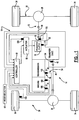
- a drivetrain 10 for a four-wheel drive vehicle includes a first driveline 12, a second driveline 14, and a powertrain 16 for delivering rotary tractive power (i.e., drive torque) to the first and second drivelines.
- first driveline 12 is the rear driveline while second driveline 14 is the front driveline.
- Powertrain 16 includes an engine 18, a multi-speed transmission 20, and a power transmission device, hereinafter referred to as transfer case 22.
- Rear driveline 12 includes a pair of rear wheels 24 connected at opposite ends of a rear axle assembly 26 having a rear differential 28 coupled to one end of a rear propshaft 30, the opposite end of which is coupled to a rear output shaft 32 of transfer case 22.
- front driveline 14 includes a pair of front wheels 34 connected at opposite ends of a front axle assembly 36 having a front differential 38 coupled to one end of a front propshaft 40, the opposite end of which is coupled to a front output shaft 42 of transfer case 22.
- drivetrain 10 is shown to further include an electronically-controlled power transfer system for adaptively controlling the torque distribution between the front and rear drivelines.
- transfer case 22 is equipped with a transfer clutch 50 that can be selectively engaged for transferring drive torque from rear output shaft 32 to front output shaft 42.
- the power transfer system further includes a power-operated clutch actuator 52 for actuating transfer clutch 50, and a control system having vehicle sensors 54 for detecting certain dynamic and operational characteristics of the motor vehicle, a mode selector 56 permitting the vehicle operator to select one of the available drive modes, and a controller 58 for controlling actuation of clutch actuator 52 in response to input signals from vehicle sensors 54 and mode selector 56.
- mode selector 56 It is contemplated that as many as three different operative drive modes could be made available for selection via mode selector 56.
- a two-wheel drive (2WD) mode is established when transfer clutch 50 is released such that drive torque is only transmitted from powertrain 16 to rear driveline 12.
- a locked or part-time four-wheel drive (4WD) mode is established when transfer clutch 50 is fully engaged such that drive torque is transmitted equally to both drivelines.
- an all-wheel drive (AWD) mode is established when power-operated clutch actuator 52 is adaptively controlled for controlling engagement of transfer clutch 50.
- AWD all-wheel drive
- an active full-time torque control strategy is utilized by the control system when the AWD mode is selected. This control strategy is intended to mimic operation of an interaxle differential by maintaining a predetermined torque distribution ratio between the front and rear drivelines.
- Transfer case 22 is schematically shown in Figure 2 to include a housing 60 from which rear output shaft 32 is rotatably supported.
- Rear output shaft 32 includes a first end segment 62 adapted for connection to the output shaft of transmission 20 and a second end segment 64 to which a yoke 66 is secured for connection to rear propshaft 30.
- Front output shaft 42 is likewise rotatably supported in housing 60 and includes a yoke segment 68 adapted for connection to front propshaft 40.
- Transfer clutch 50 is operably arranged to transfer rotary power (i.e., drive torque) from rear output shaft 32 to front output shaft 42 through a transfer assembly 70.
- Transfer assembly 70 includes a first sprocket 72, a second sprocket 74, and a power chain 76 that is in driving engagement with first sprocket 72 and second sprocket 74.
- First sprocket 72 is rotatably supported on rear output shaft 32 while second sprocket 74 is coupled for rotation with front output shaft 42.
- Transfer clutch 50 includes a multi-plate friction clutch assembly 90.
- Clutch assembly 90 is shown to include a clutch hub 94 fixed for rotation with rear output shaft 32, a clutch drum 100 fixed for rotation with first sprocket 72, and a multi-plate clutch pack 104 operably disposed between hub 94 and drum 100.
- Clutch pack 104 includes a set of outer clutch plates 106 that are splined for rotation with and axial movement on drum 100.
- Clutch pack 104 also includes a set of inner clutch plates 108 that are splined for rotation with and axial movement on clutch hub 94.
- Clutch assembly 90 also includes a pressure plate 112 arranged to exert a compressive clutch engagement force on clutch pack 104.
- Pressure plate 112 is axially moveable relative to clutch pack 104 through a range of travel defined between a first or “released” position and a second or “locked” position. With pressure plate 112 in its released position, a minimum clutch engagement force is exerted on clutch pack 104 such that virtually no drive torque is transferred from rear output shaft 32 through clutch assembly 90 and transfer assembly 70 to front output shaft 42, thereby establishing the 2WD mode.
- pressure plate 112 in its locked position causes a maximum clutch engagement force to be applied to clutch pack 104 such that front output shaft 42 is, in effect, coupled for common rotation with rear output shaft 32, thereby establishing the 4WD mode.
- Accurate control of the position of pressure plate 112 between its released and locked positions permits adaptive regulation of the amount of drive torque transferred from rear output shaft 32 to front output shaft 42, thereby establishing the adaptive AWD mode.
- Clutch actuator 52 is provided for moving pressure plate 112 between its released and locked positions. While only a schematic version of actuator 52 is depicted in the drawings, one skilled in the art will appreciate that many types of power-operated actuator devices may be controlled using the torque control strategy of the present invention.
- clutch actuator 52 includes a power unit 116 and an apply operator device 118.
- Power unit 116 is adapted to receive electric control signals from controller 58 and generate an output force or torque in response thereto.
- a preferred power unit 116 is an electric motor having a rotary output.
- Apply operator device 118 is adapted to convert and amplify the output of power unit 116 into a linear thrust force that is applied to pressure plate 112 for causing movement thereof between its released and locked positions.
- Suitable apply operator devices include ball ramps, ball screws, sector-driven pivoting lever systems, and other similar devices.
- One example of a suitable clutch actuator 52 is shown and described in commonly-owned U.S. Patent No. 6,484,857 which is hereby incorporated by reference.
- control strategy includes a sequence of steps which function to prevent wheel slip while still providing drive torque to as many wheels as possible to help maintain vehicle traction and stability.
- controller 58 controls actuation of clutch actuator 52 in an attempt to simulate or "mimic" the operation of an interaxle differential by maintaining a desired torque split between the front and rear drivelines.
- the control strategy of the present invention is advantageous over previous on-demand systems and full-time systems equipped with mechanical differentials in that slip need not be created for the power transfer system to transfer torque to the drivelines. Therefore, vehicle traction and stability is greatly improved.
- drivetrain 10 is equipped with a variety of sensors that provide signals to controller 58.
- an engine speed sensor 126 generates a signal based on the rotational speed of engine 18.
- An engine torque signal shown schematically as sensor 128, is a signal calculated by the engine controller (not shown) that is indicative of the engine torque produced by engine 18.
- a gear position signal shown as sensor 130, is a signal from the transmission controller (not shown) indicative of the present gear in which transmission 20 is operating.
- a first speed sensor 132 generates a signal based on the rotational speed of rear output shaft 32 while a second speed sensor 134 generates a signal based on the rotational speed of front output shaft 42.
- a steering angle sensor 136 generates a signal based on the present steering angle of front wheels 34.
- a position sensor 138 generates a signal based on the linear or rotary position of a moveable component associated with transfer clutch 50 or clutch actuator 52 which is indicative of the current position of pressure plate 112 relative to clutch pack 104.
- first speed sensor 132 provides a signal indicative of transfer case output speed (TCOS).
- engine speed sensor 126 provides a signal indicative of the rotational engine speed (ES).
- gear position sensor 130 provides a signal indicative of the present gear in which transmission 20 is operating.
- TGR transmission gear ratio
- TCSR torque converter speed ratio
- a torque converter torque ratio is determined by referring to a look-up table similar to the table shown in Figure 5 .
- a torque converter torque ratio (TCTR) is determined.
- the value of the torque converter speed ratio (TCSR) calculated in step 206 is used to select a corresponding value for the torque converter torque ratio (TCTR).
- the range of (TCSR) values assigned to each corresponding (TCTR) value is indicative of the slip speed between the rotary input and output members of the vehicle's torque converter.
- the (TCTR) value is, in turn, indicative of the torque multiplication generated across the torque converter.
- the look-up values provided in Figure 5 are merely exemplary and may be modified in accordance with each particular vehicle application.
- engine torque sensor 128 provides a signal indicative of the engine torque (ET) generated by engine 18.
- TCIP transfer case input torque
- a desired torque split percentage (TSP) value is selected to define the percentage of the total drive torque to be transferred through transfer clutch 50 to front driveline 14.
- TSP torque split percentage
- a torque split of 40% to the front axle and 60% to the rear axle will be used.
- the desired torque split may be a preset value as indicated or may be a dynamic value which is varied during vehicle operation based on detected operating characteristics.
- a clutch actuator position is determined at step 218.
- the torque transmission characteristics of friction clutch assembly 90 are correlated to the position of a moveable component of clutch actuator 52 in a look-up table similar to the table provided in Figure 6 .
- the first column provides a predetermined number of value ranges for the transfer case desired torque (TCDT) to be generated by engagement of transfer clutch 50. For each of these ranges, a corresponding clutch actuator position (CAP) is assigned in the second column.
- Each clutch actuator position (CAP) value is an integer that is indicative of an incremental change in the position of pressure plate 112 relative to clutch pack 104 that is required to transfer the "target" torque value (TCDT) to front output shaft 42 so as to maintain the desired 40/60 torque split.
- the (TCDP) value of 0 is indicative of pressure plate 112 being located in its locked position for fully engaging transfer clutch 50. Therefore, each sequential (CAP) value (i.e., 0-10) indicates an incremental amount of travel that pressure plate 112 is offset or retracted from its locked position in a direction toward its released position.
- a transfer case desired torque (TCDT) of 395 Ib-ft corresponds to a clutch actuator position (CAP) of five.
- the look-up table in Figure 6 depicts eleven different positions for maintaining the desired torque split between the front and rear drivelines. Obviously, skilled artisans will understand that the specific number of discrete positional increments actually used can be varied to accommodate the torque transfer and clutch apply characteristics for each particular four-wheel drive application. As feedback to assist in precisely positioning pressure plate 112 to achieve the targeted torque transfer, a signal from position sensor 138 is used by controller 58 to identify the actual position and make any fine adjustments required, such as for wear anticipated after prolonged service.
- steering angle sensor 136 provides a signal indicative of the steering angle to controller 58 at step 220. If the vehicle is turning, and the vehicle speed is below a maximum threshold value (i.e., 20 mph), the value of the transfer case desired torque (TCDT) previously determined in step 216 will be reduced to avoid binding and/or front drive wheel slip.
- Figure 7 depicts an apply look-up table which correlates steering angle to a positional offset value. In essence, if the vehicle is operating at low speed and the operator attempts to make a tight (high angle) turn, then the clutch actuator position (CAP) value determined in step 218 is adjusted to reduce the drive torque transmitted to front driveline 14. Given a steering angle of 200 degrees, the look-up table depicts a steering angle offset (SO) value equal to 2.
- the adjusted clutch actuator position (ACAP) is determined using the following equation.
- the targeted amount of drive torque to be transmitted through transfer clutch 50 during such a low-speed high angle turn would be equal to the (TCDT) value corresponding to the 7th clutch actuator position (CAP), as shown in the look-up table of Figure 6 .
- the previously described strategy may be continuously implemented during vehicle operation or selectively invoked by the operator via shifting mode selector 56 between the available mode positions. Once the control strategy is functioning, steps 200-222 are executed frequently to actively control the torque output of front wheels 34 and rear wheels 24 in an attempt to maximize vehicle stability and control.
- control strategy of the present invention has been described in relation to a driveline as depicted in Figure 1 , alternate embodiments are contemplated. In its most broad form, the control strategy of the present invention may be implemented to control virtually any power transmission device within a vehicle in which the output torque may be controlled. Moreover, Figures 8-14 depict specific embodiments which have been contemplated.
- FIG. 8 schematically depicts a front-wheel based four-wheel drivetrain layout 400 for a motor vehicle.
- engine 402 drives a multi-speed transmission 404 having an integrated front differential unit 406 for driving front wheels 34 via axle shafts 410.
- a power transfer unit 412 is also driven by transmission 404 for delivering drive torque to the input member of a torque transfer coupling 414 via a drive shaft 416.
- the input member of transfer coupling 414 is coupled to drive shaft 416 while its output member is coupled to a drive component of rear differential 28.
- controller 58 adaptively controls actuation of torque coupling 414 such that drive torque is delivered in proper proportion to rear wheels 24.
- torque transfer coupling 414 would include a multi-plate transfer clutch 50 and a clutch actuator 52 that are generally similar in structure and function to that of any of the devices previously described herein. While shown in association with rear differential 28, it is contemplated that torque coupling 414 could also be operably located for transferring drive torque from transfer unit 412 to drive shaft 416.
- torque coupling 414 is schematically illustrated in association with a four-wheel drive system based on a front-wheel drive vehicle similar to that shown in Figure 8 .
- an output shaft 424 of transmission 404 is shown to drive an output gear 426 which, in turn, drives an input gear 428 fixed to a carrier 430 associated with front differential unit 406.
- front differential unit 406 includes a pair of side gears 432 that are connected to front wheels 34 via axleshafts 410.
- Differential unit 406 also includes pinions 434 that are rotatably supported on pinion shafts fixed to carrier 430 and which are meshed with side gears 432.
- a transfer shaft 436 is provided to transfer drive torque from carrier 430 to a clutch hub 94' associated with multi-pate clutch assembly 90'.
- Clutch assembly 90' further includes a drum 100' and a clutch pack 104' having interleaved clutch plates operably connected between hub 94' and drum 100'.
- Transfer unit 412 is a right-angled drive mechanism including a ring gear 446 fixed for rotation with drum 100' of clutch assembly 90' which is meshed with a pinion gear 448 fixed for rotation with drive shaft 416.
- a clutch actuator 52 is schematically illustrated for controlling actuation of clutch assembly 90'.
- FIG 10 illustrates a modified version of Figure 9 wherein an on-demand four-wheel drive system is shown based on a rear-wheel drive motor vehicle that is arranged to normally deliver drive torque to rear wheels 24 while selectively transmitting drive torque to front wheels 34 through torque coupling 414.
- drive torque is transmitted directly from transmission output shaft 424 to transfer unit 412 via a drive shaft 456 interconnecting input gear 428 to ring gear 446.
- torque coupling 414 is now shown operably disposed between drive shaft 456 and transfer shaft 436.
- clutch assembly 90' is arranged such that drum 100' is driven with ring gear 446 by drive shaft 456.
- actuation of clutch actuator 52 functions to transfer torque from drum 100' through clutch pack 104' to hub 94' which, in turn, drives carrier 430 of front differential unit 406 via transfer shaft 436. Accordingly, continuous adaptive traction control is provided.
Landscapes
- Engineering & Computer Science (AREA)
- Chemical & Material Sciences (AREA)
- Combustion & Propulsion (AREA)
- Transportation (AREA)
- Mechanical Engineering (AREA)
- Arrangement And Driving Of Transmission Devices (AREA)
- Mechanical Operated Clutches (AREA)
Claims (15)
- Leistungsübertragungsvorrichtung (22), umfassend:ein rotierendes Eingangselement (32), das angepasst ist, um ein Antriebsdrehmoment von einer Leistungsquelle (16) zu empfangen;ein rotierendes Ausgangselement (42), das angepasst ist, um ein Antriebsdrehmoment an eine Ausgabevorrichtung bereitzustellen;einen Drehmomentverteilungsmechanismus, der zum Verteilen eines Antriebsdrehmoments von dem Eingangselement (32) an das Ausgangselement (42) betreibbar ist, wobei der Drehmomentübertragungsmechanismus eine Reibungskupplungsanordnung (90; 90'), die zwischen dem Eingangselement und dem Ausgangselement wirksam angeordnet ist, und einen Kupplungsaktor (52), der eine Kupplungseingriffskraft an die Reibungskupplungsanordnung (90; 90') anlegt, aufweist; undein Steuerungssystem (58), das die Betätigung des Kupplungsaktors (52) derart steuert, dass eine gewünschte Drehmomentsaufteilung (TSP) erhalten bleibt, wobei das Steuerungssystem ein für die Verteilung verfügbares Gesamtdrehmoment berechnet, ein gewünschtes Drehmoment berechnet, um es an das Ausgangselement (TCDT) zu verteilen, das auf dem für die Verteilung verfügbaren Gesamtdrehmoment (TCIP) und der gewünschten Drehmomentsaufteilung (TSP) basiert, und den Kupplungsaktor (52) positioniert, um das gewünschte Drehmoment (TCDT) durch die Reibungskupplungsanordnung (90; 90') zu übertragen,dadurch gekennzeichnet, dass
Drehmomentübertragungscharakteristika der Reibungskupplungsanordnung (90; 90') mit der Position einer Druckplatte (112) des Kupplungsaktors (52) in einer Nachschlagetabelle korreliert sind, die in einer erste Spalte eine vorbestimmte Anzahl von Wertebereichen für das gewünschte Drehmoment (TCDT), das durch den Eingriff der Reibungskupplungsanordnung (90; 90') zu erzeugen ist, bereitstellt, und die in einer zweiten Spalte für jeden dieser Wertebereiche eine entsprechende Kupplungsaktorposition (CAP) vorsieht, wobei jeder Wert der Kupplungsaktorposition (CAP) eine ganze Zahl ist, die eine inkrementelle Änderung der Position der Druckplatte (112) des Kupplungsaktors (52) angibt; und
das Steuerungssystem (58) derart ausgestaltet ist, dass es eine Kupplungsaktorposition (CAP) bestimmt, die dem berechneten Wert des gewünschten Verteilergetriebedrehmoments (TCDT) entspricht, indem die Nachschlagetabelle genutzt wird, und dass es die Druckplatte (112) des Kupplungsaktors (52) in Übereinstimmung mit der bestimmten Kupplungsaktorposition (CAP) positioniert. - Leistungsübertragungsvorrichtung nach Anspruch 1, wobei das Eingangselement eine erste Welle umfasst, die ein Antriebsdrehmoment für einen primären Antriebsstrang eines Kraftfahrzeugs bereitstellt, wobei das Ausgangselement eine zweite Welle umfasst, die mit einem sekundären Antriebsstrang des Kraftfahrzeugs gekoppelt ist, und wobei der Drehmomentverteilungsmechanismus betreibbar ist, um ein Antriebsdrehmoment von der ersten Welle zu der zweiten Welle zu übertragen.
- Leistungsübertragungsvorrichtung nach Anspruch 1, die eine Zapfwelleneinheit definiert, wobei die erste Welle ein Antriebsdrehmoment für ein dem primären Antriebsstrang zugeordnetes Primärdifferential bereitstellt und wobei die zweite Welle mit einem dem sekundären Antriebsstrang zugeordneten Sekundärdifferential gekoppelt ist.
- Leistungsübertragungsvorrichtung nach Anspruch 1, wobei das Eingangselement eine Antriebswelle ist, die von einem Antriebsstrang eines Kraftfahrzeugs angetrieben wird, wobei das Ausgangselement eine Ritzelwelle ist, die ein mit einer Achsbaugruppe des Kraftfahrzeugs verbundenes Differential antreibt, und wobei die Reibungskupplungsanordnung zwischen der Antriebswelle und der Ritzelwelle derart angeordnet ist, dass die Betätigung der Kupplungsaktoranordnung betreibbar ist, um ein Antriebsdrehmoment von der Antriebswelle zu der Ritzelwelle zu übertragen.
- Leistungsübertragungsvorrichtung nach Anspruch 1, wobei das Eingangselement ein erstes Differential, das ein Antriebsdrehmoment an ein Paar erster Räder in einem Kraftfahrzeug liefert, und eine durch das Differential angetriebene Übertragungswelle aufweist, wobei das Ausgangselement eine Antriebswelle aufweist, die mit einem zweiten Differential gekoppelt ist, das ein Paar zweiter Räder des Kraftfahrzeugs miteinander verbindet, und wobei die Reibungskupplungsanordnung zwischen der Übertragungswelle und der Antriebswelle angeordnet ist.
- Leistungsübertragungsvorrichtung nach Anspruch 1, wobei das Eingangselement eine erste Welle aufweist, die ein Antriebsdrehmoment an eine zweite Welle liefert, die mit einem ersten Differential zum Antreiben eines Paars erster Räder in einem Kraftfahrzeug gekoppelt ist, wobei das Ausgangselement eine dritte Welle ist, die ein zweites Differential antreibt, das ein Paar von zweiten Rädern des Kraftfahrzeugs miteinander verbindet, und wobei die Reibungskupplungsanordnung betriebsfähig zwischen der ersten und der dritten Welle angeordnet ist.
- Leistungsübertragungsvorrichtung nach Anspruch 1, wobei das Steuerungssystem eine Steuerung, einen Motordrehzahlsensor, der ein Motordrehzahlsignal erzeugt, einen Eingangselementdrehzahlsensor, der ein Eingangselementdrehzahlsignal erzeugt, und einen Übersetzungsgetriebepositionssensor umfasst, der ein Übersetzungsgetriebepositionssignal erzeugt, wobei die Steuerung derart betreibbar ist, dass sie das gewünschte zu verteilende Drehmoment basierend auf dem Motordrehzahlsignal, dem Eingangselementdrehzahlsignal und dem Übersetzungsgetriebepositionssignal bestimmt.
- Leistungsübertragungsvorrichtung nach Anspruch 7, wobei das Steuerungssystem einen Motordrehmomentsensor umfasst, der ein Motordrehmomentsignal erzeugt, wobei die Steuerung derart betreibbar ist, dass sie das gewünschte zu verteilende Drehmoment basierend auf dem Motordrehmomentsignal bestimmt.
- Leistungsübertragungsvorrichtung nach einem der Ansprüche 1 bis 8, wobei der Drehmomentverteilungsmechanismus ein Verteilergetriebe (50) in Verbindung mit einem Motor und einem Getriebe ist, wobei die Kupplung bevorzugt eine Mehrblatt-Reibungskupplung ist.
- Verfahren zum Steuern der Verteilung eines Drehmoments zwischen einem rotierenden Eingangselement (32), das angepasst ist, um ein Antriebsdrehmoment von einer Energiequelle (16) zu empfangen, und einem rotierenden Ausgangselement (42), das angepasst ist, um ein Antriebsdrehmoment an eine Ausgabevorrichtung in einem Drehmomentverteilungsmechanismus bereitzustellen, der zum Verteilen eines Antriebsdrehmoments von dem Eingangselement (32) an das Ausgangselement (42) betreibbar ist, wobei der Drehmomentübertragungsmechanismus eine Reibungskupplungsanordnung (90; 90'), die zwischen dem Eingangselement und dem Ausgangselement wirksam angeordnet ist, und einen Kupplungsaktor (52), der eine Kupplungseingriffskraft an die Reibungskupplungsanordnung (90; 90') anlegt, aufweist, wobei das Verfahren umfasst:Steuern der Betätigung des Kupplungsaktors (52) derart, dass eine gewünschte Drehmomentsaufteilung (TSP) erhalten bleibt, wobei ein für die Verteilung verfügbares Gesamtdrehmoment (TCIP) berechnet wird, ein gewünschtes Drehmoment, das auf dem für die Verteilung verfügbaren Gesamtdrehmoment (TCIP) und der gewünschten Drehmomentsaufteilung (TSP) basiert, berechnet wird, um es an das Ausgangselement (TCDT) zu verteilen, und der Kupplungsaktor (52) positioniert wird, um das gewünschte Drehmoment (TCDT) durch die Reibungskupplungsanordnung (90; 90') zu übertragen, dadurch gekennzeichnet, dassDrehmomentübertragungscharakteristika der Reibungskupplungsanordnung (90; 90') mit der Position einer Druckplatte (112) des Kupplungsaktors (52) in einer Nachschlagetabelle korreliert sind, die in einer erste Spalte eine vorbestimmte Anzahl von Wertebereichen für das gewünschte Drehmoment (TCDT), das durch den Eingriff der Reibungskupplungsanordnung (90; 90') zu erzeugen ist, bereitstellt, und die in einer zweiten Spalte für jeden dieser Wertebereiche eine entsprechende Kupplungsaktorposition (CAP) vorsieht, wobei jeder Wert der Kupplungsaktorposition (CAP) eine ganze Zahl ist, die eine inkrementelle Änderung der Position der Druckplatte (112) des Kupplungsaktors (52) angibt; und dassPositionieren des Kupplungsaktors (52) zur Verteilung des gewünschten Drehmoments (TCDT) durch die Reibungskupplungsanordnung (90; 90') umfasst:Bestimmen einer Kupplungsaktorposition (CAP), die dem berechneten Wert des gewünschten Verteilergetriebedrehmoments (TCDT) entspricht, indem die Nachschlagetabelle genutzt wird; undPositionieren der Druckplatte (112) des Kupplungsaktors (52) in Übereinstimmung mit der bestimmten Kupplungsaktorposition (CAP).
- Verfahren nach Anspruch 10, wobei das Berechnen des für die Verteilung verfügbaren Gesamtdrehmoments beinhaltet:Bestimmen eines Drehmomentwandler-Drehzahlverhältnisses (TCSR);Bestimmen eines Eingangsdrehmoments für den Drehmomentübertragungsmechanismus (TCIP).
- Verfahren nach Anspruch 11, wobei der Schritt des Bestimmens eines Drehmomentwandler-Drehzahlverhältnisses (TCSR) das Bestimmen einer Motordrehzahl (ES) beinhaltet.
- Verfahren nach Anspruch 12, wobei der Schritt des Bestimmens eines Drehmomentwandler-Drehzahlverhältnisses (TCSR) das Bestimmen einer Ausgangswellendrehzahl (TCOS) des Drehmomentübertragungsmechanismus beinhaltet.
- Verfahren nach Anspruch 13, wobei der Schritt des Bestimmens eines Drehmomentwandler-Drehzahlverhältnisses (TCSR) das Bestimmen eines Übersetzungsverhältnisses einer Übertragung (TGR) beinhaltet.
- Verfahren nach Anspruch 11, wobei der Schritt des Bestimmens eines Eingangsdrehmoments (TCIP) für den Drehmomentübertragungsmechanismus das Bestimmen eines Motordrehmoments (ET) beinhaltet.
Applications Claiming Priority (2)
| Application Number | Priority Date | Filing Date | Title |
|---|---|---|---|
| US703381 | 2003-11-07 | ||
| US10/703,381 US7125364B2 (en) | 2003-11-07 | 2003-11-07 | Control strategy for active torque control |
Publications (3)
| Publication Number | Publication Date |
|---|---|
| EP1529675A2 EP1529675A2 (de) | 2005-05-11 |
| EP1529675A3 EP1529675A3 (de) | 2010-08-25 |
| EP1529675B1 true EP1529675B1 (de) | 2018-05-23 |
Family
ID=34435574
Family Applications (1)
| Application Number | Title | Priority Date | Filing Date |
|---|---|---|---|
| EP04026278.4A Expired - Lifetime EP1529675B1 (de) | 2003-11-07 | 2004-11-05 | Leistungsübertragungsvorrichtung und Verfahren zur aktiven Drehmomentsteuerung |
Country Status (2)
| Country | Link |
|---|---|
| US (3) | US7125364B2 (de) |
| EP (1) | EP1529675B1 (de) |
Families Citing this family (29)
| Publication number | Priority date | Publication date | Assignee | Title |
|---|---|---|---|---|
| JP4417203B2 (ja) * | 2004-08-23 | 2010-02-17 | 本田技研工業株式会社 | 4輪駆動車両の駆動力制御方法 |
| US7734418B2 (en) * | 2005-06-28 | 2010-06-08 | Honda Motor Co., Ltd. | Vehicle operation assisting system |
| ATE434123T1 (de) * | 2005-10-11 | 2009-07-15 | Luk Lamellen & Kupplungsbau | Antriebsstrang für ein kraftfahrzeug und verfahren zum betreiben eines solchen antriebsstrangs |
| DE102006014736A1 (de) * | 2006-03-30 | 2007-10-04 | Zf Friedrichshafen Ag | Verfahren zur Schonung der Übertragungselemente in einem Allradantriebsstrang |
| US7491145B2 (en) * | 2006-06-19 | 2009-02-17 | Magna Powertrain Usa, Inc. | Dynamic traction control system |
| CA2661139C (en) | 2006-08-21 | 2015-02-17 | Magna Powertrain Usa, Inc. | Traction control system using torque sensor for adaptive engine throttle control |
| DE102007021303B4 (de) * | 2007-05-07 | 2015-12-24 | Magna powertrain gmbh & co kg | Verfahren und Vorrichtung zum Erzeugen eines Stellsignals für einen Aktuator einer Kupplungseinheit eines Kraftfahrzeugs |
| DE102007038150B4 (de) * | 2007-08-13 | 2010-04-29 | Magna Powertrain Ag & Co Kg | Steuerverfahren für Kupplungsanordnung |
| US8958965B2 (en) * | 2007-09-13 | 2015-02-17 | Ford Global Technologies Llc | System and method for managing a powertrain in a vehicle |
| US8510003B2 (en) | 2009-04-09 | 2013-08-13 | Ford Global Technologies, Llc | Closed-loop torque phase control for shifting automatic transmission gear ratios based on friction element load estimation |
| US8738249B2 (en) | 2010-11-19 | 2014-05-27 | Ford Global Technologies, Llc | Synchronous automatic transmission up-shift control utilizing input torque signal |
| CN103596794B (zh) | 2011-04-20 | 2017-08-25 | Gkn 动力传动系统有限责任公司 | 动力传输单元 |
| US9151685B2 (en) * | 2011-08-31 | 2015-10-06 | GM Global Technology Operations LLC | Method and apparatus to determine torque in a powertrain system |
| US8620543B2 (en) * | 2012-04-13 | 2013-12-31 | GM Global Technology Operations LLC | System and method for estimating torque in a powertrain |
| GB2505020B (en) * | 2012-08-16 | 2015-09-09 | Jaguar Land Rover Ltd | Vehicle speed control system |
| GB2505021B (en) * | 2012-08-16 | 2015-09-09 | Jaguar Land Rover Ltd | Vehicle speed control system |
| US8989984B2 (en) * | 2012-10-04 | 2015-03-24 | Robert Bosch Gmbh | Method to shut off adaptive cruise control when the uphill gradient is too steep |
| US9080619B2 (en) | 2013-04-11 | 2015-07-14 | GM Global Technology Operations LLC | Clutch slip identification systems and methods |
| US9194484B2 (en) | 2013-04-11 | 2015-11-24 | GM Global Technology Operations LLC | System and method for detecting lash in a transmission and controlling an engine and/or a motor based on lash detections |
| US9701195B2 (en) | 2013-06-14 | 2017-07-11 | Dana Automotive Systems Group, Llc | Differential with torque coupling |
| US9625024B2 (en) | 2013-06-14 | 2017-04-18 | Dana Automotive Systems Group, Llc | Differential with torque coupling |
| US10408323B2 (en) | 2014-07-16 | 2019-09-10 | Dana Automotive Systems Group, Llc | Drive unit with twin side shaft torque coupling |
| US10066743B2 (en) * | 2014-11-11 | 2018-09-04 | Borgwarner Inc. | Motor driven transfer case with modular actuation |
| US10087998B2 (en) | 2014-11-19 | 2018-10-02 | Dana Automotive Systems Group, Llc | Method to control clutch force in a clutch pack |
| US10377232B2 (en) | 2015-05-12 | 2019-08-13 | Dana Automotive Systems Group, Llc | Method for synchronization control of rapid connect AWD systems |
| US10400879B2 (en) * | 2016-02-15 | 2019-09-03 | Caterpillar Inc. | One way clutch operation monitoring in torque converter |
| US10197144B2 (en) | 2017-01-20 | 2019-02-05 | Dana Heavy Vehicle Systems Group, Llc | Drive unit with torque vectoring and an axle disconnect and reconnect mechanism |
| DE102017218887B4 (de) * | 2017-10-23 | 2021-07-08 | Bayerische Motoren Werke Aktiengesellschaft | System zur Steuerung einer Antriebsmomentverteilung sowie Fahrzeug |
| US11274718B2 (en) | 2018-10-08 | 2022-03-15 | Magna Powertrain Of America, Inc. | Active brake confirmation for active transfer cases |
Citations (1)
| Publication number | Priority date | Publication date | Assignee | Title |
|---|---|---|---|---|
| US5002147A (en) * | 1987-10-27 | 1991-03-26 | Fuji Jukogyo Kabushiki Kaisha | Power transmitting system for a four-wheel drive vehicle |
Family Cites Families (34)
| Publication number | Priority date | Publication date | Assignee | Title |
|---|---|---|---|---|
| US3352373A (en) * | 1963-12-11 | 1967-11-14 | Gen Motors Corp | Vehicles with plural axles and means to provide maximum tractive effort for each axle at the same speed |
| US4715467A (en) * | 1984-03-27 | 1987-12-29 | Fuji Jukogyo Kabushiki Kaisha | Control system for a four-wheel drive vehicle |
| JPS6218117A (ja) | 1985-07-16 | 1987-01-27 | Matsushita Electric Ind Co Ltd | 音声信号符号化装置 |
| JPS6366927A (ja) | 1986-09-08 | 1988-03-25 | Toshiba Corp | 熱処理装置 |
| JPS63203958A (ja) | 1987-02-20 | 1988-08-23 | Aisin Warner Ltd | 摩擦係合装置用アクチユエ−タ |
| US4936406A (en) * | 1987-10-23 | 1990-06-26 | Fuji Jukogyo Kabushiki Kaisha | Power transmitting system for a four-wheel drive vehicle |
| JP2615085B2 (ja) * | 1987-10-27 | 1997-05-28 | 富士重工業株式会社 | 4輪駆動車のトラクション制御装置 |
| JPH01238719A (ja) | 1988-03-18 | 1989-09-22 | Tochigi Fuji Ind Co Ltd | 多板クラッチ |
| JPH0218117A (ja) | 1988-07-05 | 1990-01-22 | Tochigi Fuji Ind Co Ltd | 動力伝達装置 |
| US4989686A (en) * | 1988-07-07 | 1991-02-05 | Borg-Warner Automotive, Inc. | System for controlling torque transmission in a four wheel drive vehicle |
| JPH0366927A (ja) | 1989-07-31 | 1991-03-22 | Tochigi Fuji Ind Co Ltd | 動力伝達装置 |
| US5080641A (en) * | 1989-10-20 | 1992-01-14 | Fuji Jukogyo Kabushiki Kaisha | Torque split control system for a four-wheel drive motor vehicle |
| US5423235A (en) | 1990-02-14 | 1995-06-13 | Gkn Automotive Ag | Device for switching on a drive train |
| US5270930A (en) * | 1990-11-30 | 1993-12-14 | Mitsubishi Jidosha Kogyo Kabushiki Kaisha | Four wheel driving vehicle of a front/rear wheel differential operation limiting type |
| US5407024A (en) | 1992-06-24 | 1995-04-18 | Borg-Warner Automotive, Inc. | On demand vehicle drive system |
| US5330030A (en) | 1993-03-09 | 1994-07-19 | New Venture Gear, Inc. | Two-speed transfer case with electronic torque modulation |
| US5363938A (en) | 1993-03-09 | 1994-11-15 | New Venture Gear, Inc. | Power transfer system for a four-wheel drive vehicle |
| US6071207A (en) * | 1993-03-10 | 2000-06-06 | New Venture Gear, Inc. | Full-time transfer case with mode shift arrangement |
| US5323871A (en) | 1993-03-10 | 1994-06-28 | New Venture Gear, Inc. | Rotary actuation mechanism for torque modulated transfer case |
| JP3033416B2 (ja) * | 1993-12-28 | 2000-04-17 | 日産自動車株式会社 | 車両の前後輪間駆動力配分制御装置 |
| JP3275563B2 (ja) * | 1994-09-21 | 2002-04-15 | 日産自動車株式会社 | 車両の四輪駆動制御装置 |
| US5813490A (en) * | 1994-09-21 | 1998-09-29 | Nissan Motor Co., Ltd. | Four Wheel drive system for automotive vehicle |
| JP3384167B2 (ja) * | 1995-02-15 | 2003-03-10 | 日産自動車株式会社 | 4輪駆動車のトランスファ油圧制御装置 |
| US6142905A (en) * | 1997-03-21 | 2000-11-07 | New Venture Gear, Inc. | Full-time four-wheel drive transmission with limited slip clutch |
| US6697725B1 (en) * | 2000-01-04 | 2004-02-24 | Honda Giken Kogyo Kabushiki Kaisha | Load-based torque redistribution method in 4-wheel drive vehicle |
| JP3694212B2 (ja) * | 2000-03-28 | 2005-09-14 | 本田技研工業株式会社 | 車輪速センサの故障判定装置 |
| JP4638065B2 (ja) * | 2001-02-08 | 2011-02-23 | 富士重工業株式会社 | 4輪駆動車の制御装置 |
| JP4230124B2 (ja) * | 2001-04-20 | 2009-02-25 | 富士重工業株式会社 | 車両運動制御装置 |
| JP2002316633A (ja) * | 2001-04-20 | 2002-10-29 | Fuji Heavy Ind Ltd | 車両運動制御装置 |
| JP3582521B2 (ja) * | 2002-08-13 | 2004-10-27 | 日産自動車株式会社 | 4輪駆動車両の駆動力制御装置 |
| US6808037B1 (en) * | 2003-04-08 | 2004-10-26 | New Venture Gear, Inc. | On-demand transfer case |
| US6997299B2 (en) * | 2003-07-28 | 2006-02-14 | Magna Powertrain, Inc. | Hydraulic clutch actuation system |
| US7007763B2 (en) * | 2003-09-19 | 2006-03-07 | Borgwarner Inc. | Control system for interactive driveline and vehicle control |
| US6834225B1 (en) * | 2004-02-09 | 2004-12-21 | Ford Global Technologies, Llc | Method and system for controlling a transfer case clutch to avoid wheel slip |
-
2003
- 2003-11-07 US US10/703,381 patent/US7125364B2/en not_active Expired - Lifetime
-
2004
- 2004-11-05 EP EP04026278.4A patent/EP1529675B1/de not_active Expired - Lifetime
-
2006
- 2006-08-22 US US11/507,819 patent/US7445581B2/en not_active Expired - Lifetime
-
2008
- 2008-11-03 US US12/263,824 patent/US7611441B2/en not_active Expired - Lifetime
Patent Citations (1)
| Publication number | Priority date | Publication date | Assignee | Title |
|---|---|---|---|---|
| US5002147A (en) * | 1987-10-27 | 1991-03-26 | Fuji Jukogyo Kabushiki Kaisha | Power transmitting system for a four-wheel drive vehicle |
Also Published As
| Publication number | Publication date |
|---|---|
| US7445581B2 (en) | 2008-11-04 |
| US20090062071A1 (en) | 2009-03-05 |
| EP1529675A3 (de) | 2010-08-25 |
| US20070037662A1 (en) | 2007-02-15 |
| US7611441B2 (en) | 2009-11-03 |
| US20050101438A1 (en) | 2005-05-12 |
| EP1529675A2 (de) | 2005-05-11 |
| US7125364B2 (en) | 2006-10-24 |
Similar Documents
| Publication | Publication Date | Title |
|---|---|---|
| EP1529675B1 (de) | Leistungsübertragungsvorrichtung und Verfahren zur aktiven Drehmomentsteuerung | |
| EP1466777B1 (de) | Bedarfsabhängiges Verteilergetriebe | |
| US7111716B2 (en) | Power-operated clutch actuator for torque transfer mechanisms | |
| US7338403B2 (en) | Torque coupling with power-operated clutch actuator | |
| US6905436B2 (en) | Two-speed transfer case with adaptive clutch control | |
| US6945374B2 (en) | Active torque coupling with hydraulically-actuated ball ramp clutch assembly | |
| US6766889B1 (en) | Wedge fork clutch actuator for driveline clutches | |
| WO2006060139A2 (en) | Torque vectoring device having an electric motor/brake actuator and friction clutch | |
| EP1907719B1 (de) | Strombetriebener kupplungsaktuator für drehmomentkopplungen | |
| US6755290B1 (en) | Power transmission device for a four-wheel drive vehicle | |
| US20070095628A1 (en) | Power-operated clutch actuator for torque transfer mechanisms | |
| US20040180748A1 (en) | Torque transfer system with two stage ball ramp/clutch actuation | |
| US6988602B2 (en) | Torque transfer coupling with magnetorheological clutch actuator |
Legal Events
| Date | Code | Title | Description |
|---|---|---|---|
| PUAI | Public reference made under article 153(3) epc to a published international application that has entered the european phase |
Free format text: ORIGINAL CODE: 0009012 |
|
| AK | Designated contracting states |
Kind code of ref document: A2 Designated state(s): AT BE BG CH CY CZ DE DK EE ES FI FR GB GR HU IE IS IT LI LU MC NL PL PT RO SE SI SK TR |
|
| AX | Request for extension of the european patent |
Extension state: AL HR LT LV MK YU |
|
| 17P | Request for examination filed |
Effective date: 20051026 |
|
| PUAL | Search report despatched |
Free format text: ORIGINAL CODE: 0009013 |
|
| AK | Designated contracting states |
Kind code of ref document: A3 Designated state(s): AT BE BG CH CY CZ DE DK EE ES FI FR GB GR HU IE IS IT LI LU MC NL PL PT RO SE SI SK TR |
|
| AX | Request for extension of the european patent |
Extension state: AL HR LT LV MK YU |
|
| RIC1 | Information provided on ipc code assigned before grant |
Ipc: B60K 23/08 20060101AFI20100719BHEP |
|
| 17Q | First examination report despatched |
Effective date: 20110329 |
|
| AKX | Designation fees paid |
Designated state(s): DE FR GB IT |
|
| GRAP | Despatch of communication of intention to grant a patent |
Free format text: ORIGINAL CODE: EPIDOSNIGR1 |
|
| INTG | Intention to grant announced |
Effective date: 20171206 |
|
| GRAS | Grant fee paid |
Free format text: ORIGINAL CODE: EPIDOSNIGR3 |
|
| GRAA | (expected) grant |
Free format text: ORIGINAL CODE: 0009210 |
|
| AK | Designated contracting states |
Kind code of ref document: B1 Designated state(s): DE FR GB IT |
|
| REG | Reference to a national code |
Ref country code: GB Ref legal event code: FG4D |
|
| REG | Reference to a national code |
Ref country code: DE Ref legal event code: R096 Ref document number: 602004052731 Country of ref document: DE |
|
| RIC2 | Information provided on ipc code assigned after grant |
Ipc: B60K 23/08 20060101AFI20100719BHEP |
|
| REG | Reference to a national code |
Ref country code: DE Ref legal event code: R097 Ref document number: 602004052731 Country of ref document: DE |
|
| PG25 | Lapsed in a contracting state [announced via postgrant information from national office to epo] |
Ref country code: IT Free format text: LAPSE BECAUSE OF FAILURE TO SUBMIT A TRANSLATION OF THE DESCRIPTION OR TO PAY THE FEE WITHIN THE PRESCRIBED TIME-LIMIT Effective date: 20180523 |
|
| PLBE | No opposition filed within time limit |
Free format text: ORIGINAL CODE: 0009261 |
|
| STAA | Information on the status of an ep patent application or granted ep patent |
Free format text: STATUS: NO OPPOSITION FILED WITHIN TIME LIMIT |
|
| 26N | No opposition filed |
Effective date: 20190226 |
|
| GBPC | Gb: european patent ceased through non-payment of renewal fee |
Effective date: 20181105 |
|
| PG25 | Lapsed in a contracting state [announced via postgrant information from national office to epo] |
Ref country code: FR Free format text: LAPSE BECAUSE OF NON-PAYMENT OF DUE FEES Effective date: 20181130 |
|
| PG25 | Lapsed in a contracting state [announced via postgrant information from national office to epo] |
Ref country code: GB Free format text: LAPSE BECAUSE OF NON-PAYMENT OF DUE FEES Effective date: 20181105 |
|
| PGFP | Annual fee paid to national office [announced via postgrant information from national office to epo] |
Ref country code: DE Payment date: 20230912 Year of fee payment: 20 |
|
| REG | Reference to a national code |
Ref country code: DE Ref legal event code: R071 Ref document number: 602004052731 Country of ref document: DE |