EP1529670B1 - Fahrzeugtürrahmen und Verfahren zu seiner Herstellung - Google Patents
Fahrzeugtürrahmen und Verfahren zu seiner Herstellung Download PDFInfo
- Publication number
- EP1529670B1 EP1529670B1 EP04078023A EP04078023A EP1529670B1 EP 1529670 B1 EP1529670 B1 EP 1529670B1 EP 04078023 A EP04078023 A EP 04078023A EP 04078023 A EP04078023 A EP 04078023A EP 1529670 B1 EP1529670 B1 EP 1529670B1
- Authority
- EP
- European Patent Office
- Prior art keywords
- elongated member
- vehicle door
- forming
- door frame
- slit
- Prior art date
- Legal status (The legal status is an assumption and is not a legal conclusion. Google has not performed a legal analysis and makes no representation as to the accuracy of the status listed.)
- Expired - Lifetime
Links
- 238000000034 method Methods 0.000 title claims description 67
- 238000004519 manufacturing process Methods 0.000 title claims description 27
- 238000005452 bending Methods 0.000 claims description 44
- 238000001125 extrusion Methods 0.000 claims description 3
- 238000009966 trimming Methods 0.000 claims description 3
- 238000003825 pressing Methods 0.000 claims description 2
- 238000007730 finishing process Methods 0.000 description 5
- 238000005520 cutting process Methods 0.000 description 3
- 239000000463 material Substances 0.000 description 2
- 229910000831 Steel Inorganic materials 0.000 description 1
- 229910052782 aluminium Inorganic materials 0.000 description 1
- XAGFODPZIPBFFR-UHFFFAOYSA-N aluminium Chemical compound [Al] XAGFODPZIPBFFR-UHFFFAOYSA-N 0.000 description 1
- 229910001234 light alloy Inorganic materials 0.000 description 1
- 229910052751 metal Inorganic materials 0.000 description 1
- 239000002184 metal Substances 0.000 description 1
- 230000002787 reinforcement Effects 0.000 description 1
- 239000010959 steel Substances 0.000 description 1
- 238000003466 welding Methods 0.000 description 1
Images


Classifications
-
- B—PERFORMING OPERATIONS; TRANSPORTING
- B60—VEHICLES IN GENERAL
- B60J—WINDOWS, WINDSCREENS, NON-FIXED ROOFS, DOORS, OR SIMILAR DEVICES FOR VEHICLES; REMOVABLE EXTERNAL PROTECTIVE COVERINGS SPECIALLY ADAPTED FOR VEHICLES
- B60J5/00—Doors
- B60J5/04—Doors arranged at the vehicle sides
- B60J5/0401—Upper door structure
- B60J5/0402—Upper door structure window frame details, including sash guides and glass runs
-
- Y—GENERAL TAGGING OF NEW TECHNOLOGICAL DEVELOPMENTS; GENERAL TAGGING OF CROSS-SECTIONAL TECHNOLOGIES SPANNING OVER SEVERAL SECTIONS OF THE IPC; TECHNICAL SUBJECTS COVERED BY FORMER USPC CROSS-REFERENCE ART COLLECTIONS [XRACs] AND DIGESTS
- Y10—TECHNICAL SUBJECTS COVERED BY FORMER USPC
- Y10T—TECHNICAL SUBJECTS COVERED BY FORMER US CLASSIFICATION
- Y10T29/00—Metal working
- Y10T29/49—Method of mechanical manufacture
- Y10T29/49616—Structural member making
- Y10T29/49622—Vehicular structural member making
-
- Y—GENERAL TAGGING OF NEW TECHNOLOGICAL DEVELOPMENTS; GENERAL TAGGING OF CROSS-SECTIONAL TECHNOLOGIES SPANNING OVER SEVERAL SECTIONS OF THE IPC; TECHNICAL SUBJECTS COVERED BY FORMER USPC CROSS-REFERENCE ART COLLECTIONS [XRACs] AND DIGESTS
- Y10—TECHNICAL SUBJECTS COVERED BY FORMER USPC
- Y10T—TECHNICAL SUBJECTS COVERED BY FORMER US CLASSIFICATION
- Y10T29/00—Metal working
- Y10T29/49—Method of mechanical manufacture
- Y10T29/49826—Assembling or joining
- Y10T29/49908—Joining by deforming
Definitions
- This invention generally relates to vehicle door frames and a method for manufacturing the same.
- a known method for manufacturing a vehicle door frame includes an elongated member forming process, a liner inserting process, a first bending process, a notch portion forming process, a second bending process and a vehicle door frame finishing process.
- an elongated member forming process an elongated member, having a hollow main body and a flange portion such that the member has a predetermined cross section, is made of a sheet material.
- the liner inserting process a liner is inserted into the hollow main body of the elongated member up to a predetermined position along its length.
- the elongated member is bent at the predetermined position along its length where the liner is inserted, thereby forming a bent portion with a large radius of curvature (e.g. a radius of curvature greater than or equal to 110 mm).
- a large radius of curvature e.g. a radius of curvature greater than or equal to 110 mm.
- the flange portion of the elongated member is trimmed off along this bent portion, thereby forming a notch portion.
- the bent portion of the elongated member is further bent to a smaller radius of curvature (e.g. a radius of curvature from 20 mm to 50 mm).
- a bracket is fixed into the notch portion. In this way a vehicle door frame is manufactured.
- the elongated member is pressed, by an applied force, to a bender which has a large radius of curvature so as to form a bent portion with a corresponding large radius of curvature.
- the bent portion is formed with the hollow main body is directly in contact with the bender and such that the flange portion of the elongated member forms the outer edge of the bent portion.
- the bent portion is formed without harming the cross sectional shape of the hollow main body or flange portion.
- the flange portion of the elongated member is trimmed off along a length of the elongated member which includes the bent portion, thereby forming said notch portion.
- Said notch portion prevents the remaining flange portions of the elongated member from being damaged by any subsequent bending processes applied to the bent portion and thereby facilitates further bending of the bent portion to a smaller radius of curvature in the second bending process. This is because the bent portion of the elongated member will now only consist of the hollow main body, the flange portion having been trimmed off along this length.
- the elongated member In the second bending process, the elongated member is firmly fixed, by clamps, over a significant length of the elongated member either side of the bent portion without harming the cross sectional shape of the elongated member. A force is then applied to the fixed portions of the elongated member so as to further bend the bent portion to a smaller radius of curvature.
- an additional flange member is fitted into the notch portion of the elongated member, which now includes a bent portion with a small radius of curvature.
- a bent portion with a small radius of curvature may be formed in a vehicle door frame in stages, for example first and second bending processes.
- the flange portion would fracture if it experienced the force need to bend the intact elongated member below a certain limiting radius of curvature.
- This limiting radius of curvature is greater than those normally produced in the second bending process.
- a bent portion with a small radius of curvature is easily formed from the bent portion with a large radius of curvature by bending only the hollow main body of the elongated member. This is because the notch portion is provided at the bent portion formed in the first bending process by trimming off the flange portion along this length of the elongated member. To bend such a hollow main body, a force smaller than the force required in the first bending process is needed. Thus, a bent portion with a small radius of curvature (e.g. a radius of curvature from 20 to 50mm) is formed in the elongated member.
- a small radius of curvature e.g. a radius of curvature from 20 to 50mm
- the elongated member is bent in two stages, namely the first and the second bending processes.
- the force applied to the elongated member in each stage is different due to the differing structures being bent and the different radii of curvatures produced. This complicates the operation at each stage.
- the cost of manufacturing a vehicle door frame is increased.
- each end of the elongated member in the second bending process must be firmly secured, by a clamp or clamps, over a significant length in order to form a bent portion with a small radius of curvature.
- Each secured portion of the elongated member must be at least a certain minimum length. Therefore a bent portion with a small radius of curvature can only be formed at positions which are said minimum length away from either end of the elongated member. For this reason the freedom in the design of door frames is restricted by the use of such a manufacturing method.
- the invention provides a method for manufacturing a vehicle door frame containing the features of claim 1.
- the elongated member can be easily bent, during the bending process, over the length where the slit has been provided in the slit forming process.
- a bent portion may therefore be formed in a single step without the need for bending the elongated member in stages.
- the magnitude of the force applied during bending need not be changed because the bent portion is formed in a single step performed by a single bender.
- the bending process is simplified and as a result manufacturing costs can be reduced.
- the length of the slit provided in the slit forming process is preferably the same length as, and is positioned at, the outer surface of the hollow main body along the bent portion.
- the part of the connecting portion and the flange portion positioned outside of the slit are separated from the part of the connecting member and the hollow main body positioned inside of the slit, and the flange portion and the connecting member along the rest of the length of the elongated member remain integrated with the hollow main body.
- the notch portion is formed by cutting the flange portion at each end of the bent portion, specifically by cuts from each end of the slit to the outer edge of the flange portion so that the part of the connecting portion and the flange portion positioned outside the slit are trimmed off. Thus, the notch portion is formed easily.
- a vehicle door frame including an elongated member, formed by extrusion or roll forming, having a hollow main body, a connecting portion extending from the hollow main body, a flange portion extending from the connecting portion and a plurality of bent portions formed in the longitudinal direction of the elongated member is characterized in that at least one of the bent portions is formed, by the above method, at, or close to, one of the longitudinal end portions of the elongated member and in such a manner that the flange portion is the outer part of said bent portion; said bent portion being such that its radius of curvature is smaller than the limiting radius of curvature at which a bent portion formed by conventional means would experience fracture of the flange portion.
- a bent portion with a small radius of curvature can be formed at the end portion of an elongated member a vehicle door frame with a complicated form can be manufactured.
- freedom in the design of the vehicle door frames is enhanced.
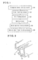
- an elongated member 10 is formed in an elongated member forming process S10 (elongated member forming step).
- the elongated member 10 with a predetermined form in cross section as shown in Fig. 2 , may be formed by extruding a light-alloy or metal, such as aluminum, by means of an extruder.
- the elongated member 10 includes a hollow main body 12, a connecting portion 13 and a flange portion 14.
- the hollow main body 12 includes a hollow 12h at the centre thereof, and the flange portion 14, which extends in upper direction in Fig. 2 , is integrally connected to the hollow main body 12 by the connecting portion 13 which is formed therebetween.
- an elongated member 10 comprising a hollow main body 12, a connecting portion 13 and a flange portion 14 is integrally formed at the elongated member forming process S10.
- the elongated member 10 When the elongated member 10 is made of steel it may be formed by means of roll forming so that it has the same aforementioned form in cross section.
- a liner 20, formed separately to the elongated member is inserted into the hollow 12h of the hollow main body 12 at a predetermined position where a bent portion 10a is going to be formed.
- the liner 20 acts as reinforcement to the hollow main body 20 when the elongated member 10 is bent so that it keeps the same cross sectional shape.
- the liner 20 is inserted within the elongated member 10 so that its centre in the longitudinal direction is positioned where the apex of the bent portion 10a to be formed will be.
- a roll which will form the slit in the elongated member 10 is attached to a roll forming machine (not shown).
- the elongated member 10 is then inserted into the roll forming machine so as to form a through slit 16 in the connecting member 13 provided between the hollow main body 12 and the flange portion 14 of the elongated member 10 as shown in Fig. 4 .
- the slit 16 through the elongated member 10 is formed along that portion of the length of the elongated member which is subsequently formed into the bent portion in the bending process.
- a laser machine or a pressing machine may be used to form the slit 16.
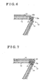
- the elongated member 10 is pressed around a bending form (not shown) with a small radius of curvature by a force applied to the elongated member 10 either side of the portion to be bent.
- a bent portion 10a with a small radius of curvature is formed in the elongated member 10 in the portion where the liner 20 was previously inserted, the bend being alongside the slit 16 which was formed in the connecting portion 13 between the hollow main body 12 and the flange portion 14. Therefore only the hollow main body 12 and the part of the connecting portion 13 radially inwardly of the slit 16 will have been bent to fit the shape of the bender.
- the elongated member 10 can be bent in a single stage to a small radius of curvature at the portion where the slit 16 is formed, the radius of curvature of the bent portion can be, for example, 20 to 50mm. In the embodiment of the invention shown in figures 5 to 7 the radius of curvature of the bent portion 10a is set to be 40 mm.
- the magnitude of the force applied to the elongated member 10 in the bending process is limited to be below the limit at which the material of the elongated member 10 away from the bent portion would be elongated.
- the length of the slit 16 is the longitudinal length of the outer surface of the bent portion 10a of the hollow main body 12 of the elongated member 10.
- the flange portion 14 and the part of the connecting portion 13 positioned outside of the slit 16 are separated from the part of the connecting member 13 positioned inside the slit 16 and the hollow main body 12.
- the connecting member 13 and the flange portion 14 remaining integrated with the hollow main body 12 over the rest of the length of the elongated member 10.
- the connecting portion and the part of the flange portion 14 positioned outside of the slit 16 are also bent and form a separate bent portion 10c with a large radius of curvature.
- the radius of curvature of this bent portion 10c is more than the limiting radius of curvature at which fracture of the flange portion 14 would occur and the radius of curvature of the bent portion 10a is less than the same limiting radius of curvature.
- a notch portion 10b is formed by trimming off the part of the flange portion 14 and the connecting portion 13 positioned outside of the slit 16.
- the notch portion 10b can be formed by cutting off the flange portion 14 and connecting portion 13 positioned outside of the slit 10c, in other words, by cutting from each end of the slit 16 to the outer edge of the flange portion 14 so that the part of the connecting portion 13 and the flange portion 14 positioned outside the slit 16 are trimmed off.
- the notch portion 10b is formed easily
- a bracket 60 whose shape in cross section is identical with the cross sectional shape of the portion of the elongated member 10 that has been trimmed off is attached by welding or similar means to fill the notch portion 10b of the elongated member 10. In this manner a vehicle door frame is manufactured.
- the elongated member 10 is bent in a single stage, unlike the known manufacturing method in which the elongated member 10 is bent in successive stages. Furthermore in this embodiment of the invention the amount force applied during bending need not be changed as the bending process S40 is performed by a single bender in a single step. In this way, as a simpler bending process S40 is provided, the manufacturing cost can be reduced.
- a bent portion 10a with a small radius of curvature can be formed with a reduced production cost.
- Figs. 8(A) and (B) illustrate examples of vehicle door frames manufactured by the above embodiment of the present invention.
- the door frame in Fig. 8(A) includes a gentle curve extending from the left side toward the upper right and a bent portion 10a with a small radius of curvature formed at what was approximately the longitudinal centre portion of the elongated member 10 as it was before it was subject to any bending processes.
- Such a vehicle door frame is normally situated at the front of the side of a vehicle body 70.
- Fig. 8(B) Additional examples of vehicle door frames are shown in Fig. 8(B) .
- Both door frames include a bent portion 10a with a small radius of curvature formed at what was approximately the longitudinal centre of each elongated member 10 as it was before it was subject to any bending processes.
- each elongated member 10 includes a plurality of bent portions 10a in the longitudinal direction of the elongated member 10.
- slits 16 will have been formed in the elongated members 10 in a position such that the bent portions 10a with a small radius of curvature can be provided. This is possible even at the end portion of an elongated member 10 because there is no need to hold the elongated member 10 at significant distances from the bent portion being formed during any bending process.
- the radius of curvature of the bent portions 10a provided at the ends of the elongated members 10 are smaller than the radius of curvature which would have caused fracture of the flange portion 14 had the elongated member 10 been bent by conventional means.
- a vehicle door frame with a complicated form can be manufactured because bent portions 10a with a small radius of curvature can be formed at the end portion of an elongated member 10.
- freedom in design of door frames is enhanced by such a manufacturing method and a flexibility in the design of door frames may be implemented.
Landscapes
- Engineering & Computer Science (AREA)
- Mechanical Engineering (AREA)
- Bending Of Plates, Rods, And Pipes (AREA)
- Automobile Manufacture Line, Endless Track Vehicle, Trailer (AREA)
Claims (10)
- Verfahren zum Herstellen eines Fahrzeugtürrahmens, wobei der Fahrzeugtürrahmen ein langgestrecktes Element (10) enthält, das mit einer Mehrzahl an gebogenen Bereichen in der Längsrichtung des langgestreckten Elements (10) ausgebildet ist und einen hohlen Hauptkörper (12), einen Verbindungsbereich (13), der sich von dem hohlen Hauptkörper (12) aus erstreckt, und einen Flanschbereich (14), der sich von dem Verbindungsbereich (13) aus erstreckt, aufweist, dadurch gekennzeichnet, dass das Verfahren die Schritte enthält:einen langgestrecktes Element-Ausbildungsschritt (S 10) zum Ausbilden des langgestreckten Elements (10), bei dem der hohle Hauptkörper (12), der Verbindungsbereich (13) und der Flanschbereich (14) integral geformt werden;einen Auskleidungseinführungsschritt (S20) zum Einführen einer Auskleidung (20) in den hohlen Hauptkörper (12) des langgestreckten Elements (10) in einer vorgegebenen Position davon nach dem langgestrecktes Element-Ausbildungsschritt (S 10);einen Schlitzausbildungsschritt (S30) zum Ausbilden eines Schlitzes (16) in dem Verbindungsbereich (13) in der gleichen vorbestimmten Position nach dem langgestrecktes Element-Ausbildungsschritt (S 10);einen Biegeschritt (S40) zum Ausbilden eines gebogenen Bereichs (10a) durch Biegen des langgestreckten Elements (10) nach dem Schlitzausbildungsschritt (S30) und nach dem Auskleidungseinführungsschritt (S20);einen Kerbenbereichausbildungsschritt (S50) zum Ausbilden eines Kerbenbereichs (10b) durch Abschneiden eines Teils des Flanschbereichs (14) und des Verbindungsbereichs (13), der außerhalb des Schlitzes (16) positioniert ist, nach dem Biegeschritt (S40), undeinen Fahrzeugtürrahmenendbearbeitungsschritt (S60) zum Fertigstellen des Fahrzeugtürrahmens durch Befestigen einer Klammer (60) in den Kerbenbereich (10b) des langgestreckten Elements (10) nach dem Kerbenbereichausbildungsschritt (S50).
- Verfahren zur Herstellung eines Fahrzeugtürrahmens nach Anspruch 1, wobei die Länge des Schlitzes (16), der in dem Schlitzausbildungsschritt (S30) geformt wird, die gleiche wie die Länge der Außenoberfläche des hohlen Hauptkörpers (12) des gebogenen Bereichs (10a) ist.
- Verfahren zum Herstellen eines Fahrzeugtürrahmens nach einem der vorhergehenden Ansprüche, wobei der Auskleidungseinführungsschritt weiter einen Positionierschritt zum Positionieren der Auskleidung (20) in dem langgestreckten Element (10) enthält, so dass der Zentrumsbereich davon an dem Punkt des langgestreckten Elements (10) ist, der der Scheitel des gebogenen Bereichs (10a) wird, der nachfolgend in dem langgestreckten Element (10) während des Biegevorgangs (S40) geformt wird.
- Verfahren zum Herstellen eines Fahrzeugtürrahmens nach einem der vorhergehenden Ansprüche, wobei der langgestrecktes Element-Ausbildungsschritt (S 10) das Ausbilden des langgestreckten Elements durch Extrusions- oder Rollformen enthält.
- Verfahren zum Herstellen eines Fahrzeugtürrahmens nach einem der vorhergehenden Ansprüche, wobei der Schlitzausbildungsschritt (S30) weiter einen Schritt zum Ausbilden des Schlitzes (16) an dem Verbindungsbereich (13) durch Rollformen enthält.
- Verfahren zum Herstellen eines Fahrzeugtürrahmens nach einem der Ansprüche 1 bis 4, wobei der Schlitzausbildungsschritt (S30) weiter einen Schritt zum Ausbilden des Schlitzes (16) an dem Verbindungsbereich (13) durch eine Lasermaschine oder Pressen enthält.
- Verfahren zum Herstellen eines Fahrzeugtürrahmens nach einem der vorhergehenden Ansprüche, wobei der Biegeschritt (S40) weiter einen Ausbildungsschritt zum Formen des gebogenen Bereichs (10a) durch Biegen des langgestreckten Elements (10) mit einer darauf aufgebrachten Kraft enthält.
- Verfahren zum Herstellen eines Fahrzeugtürrahmens nach Anspruch 7, wobei der Biegeschritt (S40) weiter einen Schritt zum Ausbilden des Biegebereichs (10a) durch Biegen des langgestreckten Elements (10) mit darauf aufgebrachter Kraft enthält, die das langgestreckte Element (10) nicht dehnt.
- Fahrzeugtürrahmen, enthaltend ein langgestrecktes Element (10), das durch Extrusions- oder Rollformen gebildet ist, das einen hohlen Hauptkörper (12), einen Verbindungsbereich (13), der sich von dem hohlen Hauptkörper (12) aus erstreckt, einen Flanschbereich (14), der sich von dem Verbindungsbereich (13) aus erstreckt, und eine Mehrzahl an gebogenen Bereichen, die in der Längsrichtung des langgestreckten Elements (10) geformt sind, enthält, dadurch gekennzeichnet, dass zumindest einer der gebogenen Bereiche durch das Verfahren nach einem der vorhergehenden Ansprüche an oder nahe bei einem der Endbereiche in Längsrichtung des langgestreckten Elements (10) geformt ist und so, dass der Flanschbereich der äußere Teil des gebogenen Bereichs ist; wobei der gebogene Bereich derart ist, dass sein Krümmungsradius (10a) kleiner als der Grenzkrümmungsradius ist, bei dem ein gebogener Bereich, der durch ein herkömmliches Mittel ausgebildet ist, einen Bruch des Flanschbereichs (14) erfahren würde.
- Fahrzeugtürrahmen nach Anspruch 9, wobei der Krümmungsradius des gebogenen Bereichs (10a), der an dem Endbereich in Längsrichtung des langgestreckten Elements (10) geformt ist, festgelegt ist, dass er von 20 mm bis 50 mm ist.
Applications Claiming Priority (2)
| Application Number | Priority Date | Filing Date | Title |
|---|---|---|---|
| JP2003378790A JP4385728B2 (ja) | 2003-11-07 | 2003-11-07 | 車両用ドアフレームの製造方法及び車両用ドアフレーム |
| JP2003378790 | 2003-11-07 |
Publications (2)
| Publication Number | Publication Date |
|---|---|
| EP1529670A1 EP1529670A1 (de) | 2005-05-11 |
| EP1529670B1 true EP1529670B1 (de) | 2009-03-11 |
Family
ID=34431359
Family Applications (1)
| Application Number | Title | Priority Date | Filing Date |
|---|---|---|---|
| EP04078023A Expired - Lifetime EP1529670B1 (de) | 2003-11-07 | 2004-11-03 | Fahrzeugtürrahmen und Verfahren zu seiner Herstellung |
Country Status (5)
| Country | Link |
|---|---|
| US (1) | US20050097750A1 (de) |
| EP (1) | EP1529670B1 (de) |
| JP (1) | JP4385728B2 (de) |
| CN (1) | CN100395129C (de) |
| DE (1) | DE602004019867D1 (de) |
Families Citing this family (6)
| Publication number | Priority date | Publication date | Assignee | Title |
|---|---|---|---|---|
| JP5154816B2 (ja) * | 2007-03-30 | 2013-02-27 | シロキ工業株式会社 | 車両ドアのドアサッシュ及び車両ドアのドアサッシュの切断方法 |
| JP5469425B2 (ja) * | 2009-10-14 | 2014-04-16 | シロキ工業株式会社 | 車両のドアフレーム製造方法 |
| JP5605170B2 (ja) * | 2010-11-04 | 2014-10-15 | アイシン精機株式会社 | 車両用ドアフレーム及び車両用ドアフレームの製造方法 |
| KR101055389B1 (ko) * | 2011-03-04 | 2011-08-09 | 주식회사 에이엘메탈코리아 | 프레임가공장치 |
| DE112018002398B4 (de) | 2017-05-11 | 2024-09-12 | Henniges Automotive Sealing Systems North America, Inc. | Dichtungsanordnung |
| CN107695632A (zh) * | 2017-11-13 | 2018-02-16 | 山东鲁阔车辆制造有限公司 | 封闭篷车车门框一次成型的生产工艺 |
Family Cites Families (19)
| Publication number | Priority date | Publication date | Assignee | Title |
|---|---|---|---|---|
| US3885412A (en) * | 1973-11-21 | 1975-05-27 | Lawrence T Vance | Method of fabricating curved tubing and product thereof |
| US4923203A (en) * | 1987-12-23 | 1990-05-08 | Trimble Brent J | Composite bicycle frame with crossed tubular portions |
| JPH07103457B2 (ja) * | 1989-02-10 | 1995-11-08 | トミー株式会社 | 形状記憶合金製矯正ワイヤーの形態付与方法 |
| US5211694A (en) * | 1989-06-20 | 1993-05-18 | Mazda Motor Corporation | Safety apparatus including an air bag and a safety belt supported on a vehicle with a deformable coupling |
| EP0533095B1 (de) * | 1991-09-18 | 1998-11-25 | Fujitsu Limited | Speicher mit hin- und herbewegendem Kopf |
| US5787645A (en) * | 1992-07-06 | 1998-08-04 | Ymos Aktiengesellschaft Industrieprodukte | Motor vehicle door frame |
| DE4306668A1 (de) * | 1993-03-04 | 1994-09-08 | Ymos Ag Ind Produkte | Fahrzeugtür, insbesondere Kraftfahrzeugtür |
| US6053562A (en) * | 1997-10-21 | 2000-04-25 | Peregrine Incorporated | Door for a vehicle having a structural frame member and method of assembling same |
| DE59813386D1 (de) * | 1997-11-13 | 2006-04-20 | Schade Gmbh & Co Kg | Rohbautür eines Fahrzeugs |
| JPH11227471A (ja) * | 1998-02-13 | 1999-08-24 | Toyoda Gosei Co Ltd | フロントドアウエザストリップ及びその製造方法 |
| US6647666B2 (en) * | 1998-02-13 | 2003-11-18 | Toyoda Gosei Co., Ltd. | Sealing structure of opening section in vehicle |
| FR2789749B1 (fr) * | 1999-02-16 | 2001-05-04 | Btr Sealing Systems France | Profiles rigides en matiere plastique, pour la realisation de cadres de portes de vehicules automobiles |
| DE19925521A1 (de) * | 1999-06-04 | 2000-12-14 | Wagon Automotive Gmbh | Verfahren zur Herstellung eines als Hohlprofil ausgebildeten Rahmenbogens |
| DE10043325B4 (de) * | 2000-08-23 | 2010-02-11 | Brose Fahrzeugteile Gmbh & Co. Kg | Türrahmenmodul für eine Fahrzeugtür |
| JP3814477B2 (ja) * | 2000-10-26 | 2006-08-30 | アイシン精機株式会社 | 車両用ドアフレームの製造方法 |
| DE10201203B4 (de) * | 2002-01-14 | 2004-05-27 | Drm Druckguss Gmbh | Geschlossener metallischer Rahmen als Teil einer Fahrzeugkarosserie und Verfahren zu seiner Herstellung |
| CN2565940Y (zh) * | 2002-08-14 | 2003-08-13 | 黄红霞 | 双重防漏的成套门 |
| JP4438279B2 (ja) * | 2002-10-28 | 2010-03-24 | アイシン精機株式会社 | 車両用ドアフレーム |
| DE10255251A1 (de) * | 2002-11-26 | 2004-06-09 | Wagon Automotive Gmbh | Profilrahmen |
-
2003
- 2003-11-07 JP JP2003378790A patent/JP4385728B2/ja not_active Expired - Fee Related
-
2004
- 2004-10-26 US US10/972,680 patent/US20050097750A1/en not_active Abandoned
- 2004-11-03 EP EP04078023A patent/EP1529670B1/de not_active Expired - Lifetime
- 2004-11-03 DE DE602004019867T patent/DE602004019867D1/de not_active Expired - Fee Related
- 2004-11-08 CN CNB2004100883275A patent/CN100395129C/zh not_active Expired - Fee Related
Also Published As
| Publication number | Publication date |
|---|---|
| JP2005138761A (ja) | 2005-06-02 |
| US20050097750A1 (en) | 2005-05-12 |
| JP4385728B2 (ja) | 2009-12-16 |
| CN1614186A (zh) | 2005-05-11 |
| CN100395129C (zh) | 2008-06-18 |
| EP1529670A1 (de) | 2005-05-11 |
| DE602004019867D1 (de) | 2009-04-23 |
Similar Documents
| Publication | Publication Date | Title |
|---|---|---|
| US8291595B2 (en) | Method for production of a link rod with U-shaped cross section from sheet metal for a car multi-link axle | |
| EP0303431B1 (de) | Verfahren zur Herstellung eines Chassis für Fahrzeuge | |
| US6217089B1 (en) | Bumper reinforcing member | |
| US8091318B2 (en) | Formed part for vehicle body structural member | |
| JP4985783B2 (ja) | テーラードブランク材およびそれを用いた構造部材の製造方法 | |
| US9027989B1 (en) | Extruded body component with notched flange to reduce strain in bending | |
| EP1529670B1 (de) | Fahrzeugtürrahmen und Verfahren zu seiner Herstellung | |
| US20180370469A1 (en) | Bumper reinforcement and method of manufacturing bumper reinforcement | |
| CN114715060B (zh) | 用于机动车辆的保险杠横梁及用于生产保险杠横梁的方法 | |
| WO2004085247A1 (en) | Integral frame member for an aircraft | |
| EP3604087B1 (de) | Fahrzeugbauteil und verfahren zur herstellung davon | |
| US20100314910A1 (en) | Pillar for motor vehicle and tool for making the same | |
| US20190389264A1 (en) | Method for producing motor vehicle controls and the resulting motor vehicle control | |
| US20090039677A1 (en) | Automobile Impact Beam with Integrated Brackets and The Manufacturing Method Thereof | |
| JP3814477B2 (ja) | 車両用ドアフレームの製造方法 | |
| KR20230000313U (ko) | 알루미늄 압출 어시스트암 | |
| JP2005517854A (ja) | 自動車のエキゾーストパイプの端部に被せ嵌められるカバーを製造するための方法、及びこの方法に従って製造されたカバー | |
| US7597358B2 (en) | Belt bushing for safety belt and assembling method thereof | |
| CN214184969U (zh) | 一种用于车辆的车门包边结构及其装配模具 | |
| US11142256B2 (en) | Fender apron assembly for vehicle | |
| JP3828413B2 (ja) | 展開加工用押出し形材 | |
| JP3836015B2 (ja) | トリム用インサート | |
| CN121404107A (zh) | 车辆用内饰件边缘保护件 | |
| CN117818517A (zh) | 用于车辆的保险杠及包括该保险杠的车辆 | |
| JP2000142055A (ja) | 車両用サスペンションアームおよびその製造方法 |
Legal Events
| Date | Code | Title | Description |
|---|---|---|---|
| PUAI | Public reference made under article 153(3) epc to a published international application that has entered the european phase |
Free format text: ORIGINAL CODE: 0009012 |
|
| AK | Designated contracting states |
Kind code of ref document: A1 Designated state(s): AT BE BG CH CY CZ DE DK EE ES FI FR GB GR HU IE IS IT LI LU MC NL PL PT RO SE SI SK TR |
|
| AX | Request for extension of the european patent |
Extension state: AL HR LT LV MK YU |
|
| 17P | Request for examination filed |
Effective date: 20050615 |
|
| AKX | Designation fees paid |
Designated state(s): BG DE FR GB TR |
|
| 17Q | First examination report despatched |
Effective date: 20070731 |
|
| GRAP | Despatch of communication of intention to grant a patent |
Free format text: ORIGINAL CODE: EPIDOSNIGR1 |
|
| GRAS | Grant fee paid |
Free format text: ORIGINAL CODE: EPIDOSNIGR3 |
|
| GRAA | (expected) grant |
Free format text: ORIGINAL CODE: 0009210 |
|
| AK | Designated contracting states |
Kind code of ref document: B1 Designated state(s): DE FR GB TR |
|
| REG | Reference to a national code |
Ref country code: GB Ref legal event code: FG4D |
|
| REF | Corresponds to: |
Ref document number: 602004019867 Country of ref document: DE Date of ref document: 20090423 Kind code of ref document: P |
|
| PLBE | No opposition filed within time limit |
Free format text: ORIGINAL CODE: 0009261 |
|
| STAA | Information on the status of an ep patent application or granted ep patent |
Free format text: STATUS: NO OPPOSITION FILED WITHIN TIME LIMIT |
|
| 26N | No opposition filed |
Effective date: 20091214 |
|
| GBPC | Gb: european patent ceased through non-payment of renewal fee |
Effective date: 20091103 |
|
| REG | Reference to a national code |
Ref country code: FR Ref legal event code: ST Effective date: 20100730 |
|
| PG25 | Lapsed in a contracting state [announced via postgrant information from national office to epo] |
Ref country code: FR Free format text: LAPSE BECAUSE OF NON-PAYMENT OF DUE FEES Effective date: 20091130 |
|
| PG25 | Lapsed in a contracting state [announced via postgrant information from national office to epo] |
Ref country code: DE Free format text: LAPSE BECAUSE OF NON-PAYMENT OF DUE FEES Effective date: 20100601 |
|
| PG25 | Lapsed in a contracting state [announced via postgrant information from national office to epo] |
Ref country code: GB Free format text: LAPSE BECAUSE OF NON-PAYMENT OF DUE FEES Effective date: 20091103 |
|
| PG25 | Lapsed in a contracting state [announced via postgrant information from national office to epo] |
Ref country code: TR Free format text: LAPSE BECAUSE OF FAILURE TO SUBMIT A TRANSLATION OF THE DESCRIPTION OR TO PAY THE FEE WITHIN THE PRESCRIBED TIME-LIMIT Effective date: 20090311 |