EP1529657B1 - Pneumatique adapaté comprendre des nanostructures - Google Patents
Pneumatique adapaté comprendre des nanostructures Download PDFInfo
- Publication number
- EP1529657B1 EP1529657B1 EP20040025986 EP04025986A EP1529657B1 EP 1529657 B1 EP1529657 B1 EP 1529657B1 EP 20040025986 EP20040025986 EP 20040025986 EP 04025986 A EP04025986 A EP 04025986A EP 1529657 B1 EP1529657 B1 EP 1529657B1
- Authority
- EP
- European Patent Office
- Prior art keywords
- tire
- actuators
- vehicle tyre
- vehicle
- tyre according
- Prior art date
- Legal status (The legal status is an assumption and is not a legal conclusion. Google has not performed a legal analysis and makes no representation as to the accuracy of the status listed.)
- Expired - Lifetime
Links
- 239000002086 nanomaterial Substances 0.000 title claims description 9
- 230000003044 adaptive effect Effects 0.000 title description 3
- 239000000463 material Substances 0.000 claims description 33
- 239000002245 particle Substances 0.000 claims description 18
- 239000002071 nanotube Substances 0.000 claims description 11
- 239000002717 carbon nanostructure Substances 0.000 claims description 10
- 230000000704 physical effect Effects 0.000 claims 1
- 239000010410 layer Substances 0.000 description 19
- 239000000835 fiber Substances 0.000 description 7
- 239000002121 nanofiber Substances 0.000 description 7
- 150000002500 ions Chemical class 0.000 description 5
- OKTJSMMVPCPJKN-UHFFFAOYSA-N Carbon Chemical compound [C] OKTJSMMVPCPJKN-UHFFFAOYSA-N 0.000 description 4
- 230000000694 effects Effects 0.000 description 4
- 230000010354 integration Effects 0.000 description 4
- 241000446313 Lamella Species 0.000 description 3
- 229910000831 Steel Inorganic materials 0.000 description 3
- 239000011324 bead Substances 0.000 description 3
- 125000004432 carbon atom Chemical group C* 0.000 description 3
- 239000002131 composite material Substances 0.000 description 3
- 239000010408 film Substances 0.000 description 3
- 238000004519 manufacturing process Methods 0.000 description 3
- 239000010959 steel Substances 0.000 description 3
- 238000005299 abrasion Methods 0.000 description 2
- 238000005452 bending Methods 0.000 description 2
- 239000002800 charge carrier Substances 0.000 description 2
- 238000010276 construction Methods 0.000 description 2
- 230000008602 contraction Effects 0.000 description 2
- 238000009826 distribution Methods 0.000 description 2
- 239000000446 fuel Substances 0.000 description 2
- 229910002804 graphite Inorganic materials 0.000 description 2
- 239000010439 graphite Substances 0.000 description 2
- 229910052751 metal Inorganic materials 0.000 description 2
- 239000002184 metal Substances 0.000 description 2
- 229920000642 polymer Polymers 0.000 description 2
- 230000002441 reversible effect Effects 0.000 description 2
- XMWRBQBLMFGWIX-UHFFFAOYSA-N C60 fullerene Chemical class C12=C3C(C4=C56)=C7C8=C5C5=C9C%10=C6C6=C4C1=C1C4=C6C6=C%10C%10=C9C9=C%11C5=C8C5=C8C7=C3C3=C7C2=C1C1=C2C4=C6C4=C%10C6=C9C9=C%11C5=C5C8=C3C3=C7C1=C1C2=C4C6=C2C9=C5C3=C12 XMWRBQBLMFGWIX-UHFFFAOYSA-N 0.000 description 1
- 239000006096 absorbing agent Substances 0.000 description 1
- 230000001133 acceleration Effects 0.000 description 1
- 230000006978 adaptation Effects 0.000 description 1
- 239000000956 alloy Substances 0.000 description 1
- 229910045601 alloy Inorganic materials 0.000 description 1
- 229910052799 carbon Inorganic materials 0.000 description 1
- 239000002041 carbon nanotube Substances 0.000 description 1
- 229910021393 carbon nanotube Inorganic materials 0.000 description 1
- 150000001875 compounds Chemical class 0.000 description 1
- 230000006835 compression Effects 0.000 description 1
- 238000007906 compression Methods 0.000 description 1
- 239000004020 conductor Substances 0.000 description 1
- 239000000470 constituent Substances 0.000 description 1
- 238000013016 damping Methods 0.000 description 1
- 230000001419 dependent effect Effects 0.000 description 1
- 238000011161 development Methods 0.000 description 1
- 230000018109 developmental process Effects 0.000 description 1
- 229910003460 diamond Inorganic materials 0.000 description 1
- 239000010432 diamond Substances 0.000 description 1
- 230000005684 electric field Effects 0.000 description 1
- 230000007613 environmental effect Effects 0.000 description 1
- 238000011156 evaluation Methods 0.000 description 1
- 230000003203 everyday effect Effects 0.000 description 1
- 229910003472 fullerene Inorganic materials 0.000 description 1
- 238000010438 heat treatment Methods 0.000 description 1
- 239000011159 matrix material Substances 0.000 description 1
- 150000002739 metals Chemical class 0.000 description 1
- 238000000034 method Methods 0.000 description 1
- 239000002114 nanocomposite Substances 0.000 description 1
- 229910001000 nickel titanium Inorganic materials 0.000 description 1
- 239000013307 optical fiber Substances 0.000 description 1
- 239000004033 plastic Substances 0.000 description 1
- 238000005096 rolling process Methods 0.000 description 1
- 239000012781 shape memory material Substances 0.000 description 1
- 238000010008 shearing Methods 0.000 description 1
- 230000035939 shock Effects 0.000 description 1
- 150000004760 silicates Chemical class 0.000 description 1
- 239000002356 single layer Substances 0.000 description 1
- 230000006641 stabilisation Effects 0.000 description 1
- 238000011105 stabilization Methods 0.000 description 1
- 239000000126 substance Substances 0.000 description 1
- 239000000725 suspension Substances 0.000 description 1
- 239000010409 thin film Substances 0.000 description 1
- XLYOFNOQVPJJNP-UHFFFAOYSA-N water Substances O XLYOFNOQVPJJNP-UHFFFAOYSA-N 0.000 description 1
Images

Classifications
-
- B—PERFORMING OPERATIONS; TRANSPORTING
- B60—VEHICLES IN GENERAL
- B60C—VEHICLE TYRES; TYRE INFLATION; TYRE CHANGING; CONNECTING VALVES TO INFLATABLE ELASTIC BODIES IN GENERAL; DEVICES OR ARRANGEMENTS RELATED TO TYRES
- B60C1/00—Tyres characterised by the chemical composition or the physical arrangement or mixture of the composition
-
- B—PERFORMING OPERATIONS; TRANSPORTING
- B60—VEHICLES IN GENERAL
- B60C—VEHICLE TYRES; TYRE INFLATION; TYRE CHANGING; CONNECTING VALVES TO INFLATABLE ELASTIC BODIES IN GENERAL; DEVICES OR ARRANGEMENTS RELATED TO TYRES
- B60C19/00—Tyre parts or constructions not otherwise provided for
-
- B—PERFORMING OPERATIONS; TRANSPORTING
- B60—VEHICLES IN GENERAL
- B60C—VEHICLE TYRES; TYRE INFLATION; TYRE CHANGING; CONNECTING VALVES TO INFLATABLE ELASTIC BODIES IN GENERAL; DEVICES OR ARRANGEMENTS RELATED TO TYRES
- B60C9/00—Reinforcements or ply arrangement of pneumatic tyres
- B60C9/0028—Reinforcements comprising mineral fibres, e.g. glass or carbon fibres
-
- B—PERFORMING OPERATIONS; TRANSPORTING
- B60—VEHICLES IN GENERAL
- B60C—VEHICLE TYRES; TYRE INFLATION; TYRE CHANGING; CONNECTING VALVES TO INFLATABLE ELASTIC BODIES IN GENERAL; DEVICES OR ARRANGEMENTS RELATED TO TYRES
- B60C9/00—Reinforcements or ply arrangement of pneumatic tyres
- B60C9/02—Carcasses
-
- B—PERFORMING OPERATIONS; TRANSPORTING
- B82—NANOTECHNOLOGY
- B82Y—SPECIFIC USES OR APPLICATIONS OF NANOSTRUCTURES; MEASUREMENT OR ANALYSIS OF NANOSTRUCTURES; MANUFACTURE OR TREATMENT OF NANOSTRUCTURES
- B82Y30/00—Nanotechnology for materials or surface science, e.g. nanocomposites
Definitions
- the invention relates to vehicle tires, which show an adaptive, ie selectable behavior with regard to their mechanical properties. Such behavior is desirable for vehicle tires for a variety of reasons. Thus, for example, the requirements for the tires of a vehicle change greatly as soon as the load of a vehicle changes. This problem is usually countered by adjusting the tire pressure accordingly. Likewise, it is particularly necessary for the tires of off-road vehicles to adapt the mechanical properties of the tires to the currently prevailing environmental conditions.
- German Patent Application DE 100 01 348 A1 proposes an electromechanical tire pressure control system which is arranged in the vehicle wheel and which ensures control and adaptation of the tire pressures during the journey.
- German Patent Application DE 100 01 348 A1 proposes an electromechanical tire pressure control system which is arranged in the vehicle wheel and which ensures control and adaptation of the tire pressures during the journey.
- an electric pump is used whose power is supplied via a likewise additionally provided in the wheel integrated generator. This design makes the proposed system difficult, error prone, complex and expensive.
- US Pat. No. 5,411,070 A1 discloses a generic vehicle tire with selectable mechanical properties. This vehicle tire is provided with one or more actuators for changing the physical characteristics of the vehicle tire.
- the solution according to the invention consists essentially in that the vehicle tire is provided with actuators.
- the actuators can be different structures whose physical, in particular mechanical properties can be changed due to external influences. This creates the possibility of achieving the physical / mechanical properties of the vehicle wheel as an overall system solely by changing the physical / mechanical properties of the tire.
- different tire parameters such as cross-section, elasticity or the shape of the tread to the respective driving situation such as high-speed, acceleration, deceleration, cornering or to the respective Road conditions (dry, water, snow) or adapted to the road conditions.
- An advantageous choice of the class of materials for the realization of the actuator functionality are films of shape-memory materials made of special alloys (eg NiTi). Two such micro / nano-thin films stacked allow for different voltage occupancy in them a contraction, bsw. a reversible snapping back to its original size. By stacking a plurality of such double sheets add the changes in length and Forces. Actuators made of such films are commercially available, for example, from www.robotstore.com.
- the actuators may consist of or be formed of nanostructure particles, preferably of carbon nanostructure particles. These show a number of outstanding chemical and mechanical properties. Known representatives of the carbon nanostructure particles are the so-called fullerenes, "football-like" molecules of 60 carbon atoms. Such carbon nanostructure particles have diamond-like mechanical stability at a fraction of the density of steel; Thus, they are particularly suitable for use in mechanical components, especially with regard to lightweight construction applications. In addition, carbon nanostructure particles have the special property of changing their spatial dimensions when receiving or delivering electrical charges. This behavior opens up the possibility of advantageously applying the nanostructure particles mentioned as constituents of mechanical actuators.
- a class of nanostructure particles particularly suitable for actuators are fibers, elongated giant molecules of, for example, carbon atoms.
- the fibers or films which may also consist of other materials such as silicates or metals, can be easily integrated into a material structure and cause due to the addition of individual changes in length, for example, when applying an electrical voltage a macroscopically measurable change in length. In this way it is possible, for example, to effect a desired change in shape of a vehicle tire solely by the application of an electrical voltage to the tire. Once the electric Tension is no longer applied, the tire returns to its original shape; the described process is therefore reversible.
- the fibers may be at least partially nanotubes with a diameter of about 0.4 to 30 nm.
- the carbon atoms are arranged in a regular array of hexagonal rings (hexagonal atomic lattice structure) as a tube. This arrangement corresponds to a coiled layer of graphite, but it is far superior in graphite to mechanical properties. Due to the stable carbon configuration in the tube composite Nanotubes have extreme hardness and tear resistance. The current and thermal conductivity of the nanotubes is also extraordinary - current densities of up to 1000 amperes per square centimeter can be achieved without the material starting to melt.
- the extremely high thermal conductivity (twice as high as that of the diamond) advantageously contributes to a rapid and even heat distribution in the material and thus effectively prevents the occurrence of thermally induced mechanical stresses.
- Nanotubes as actuator material are discussed, for example, in the publication S. Roth and RH Baughman "Actuators of Individual Carbon Nanotubes" (Current Applied Physics 2, 311-314 (2002)).
- a further interesting variant of the nanotubes for use in the vehicle tire according to the invention are the so-called multi-wall Bucky fibers. They consist of several nanotubes nested concentrically nested one inside the other. This structure makes it possible, for example, to store ions directly between the cylinder walls of the multi-wall Bucky Fibers; In the electric field, the ions migrate and generate this way, the change in length of the multi-wall Bucky-Fiber and thus of the surrounding material.
- the direct integration of the actuators into the material of the vehicle tire represents an interesting possibility for the realization of the vehicle tire according to the invention.
- the nanofibers can already be introduced into the elastic matrix material of the tire during production.
- the tire wall can be divided into a multiplicity of actuator segments, which partly consist of nanotubes, which preferably cause bending deformation of the tire wall segment, and partly of nanofoils, which cause an expansion of the tire wall segment.
- the desired deformations of the tire can be taken into account.
- the carbon nanostructure particles used contribute to the stabilization of the vehicle tire according to the invention due to their outstanding mechanical properties.
- the requirements for the mechanical properties of the tire material used decrease, so that the number of those materials which are suitable for use in such a vehicle tire significantly increases.
- the integration of the described actuators can be the Optimize properties of the resulting composite material in an advantageous manner with regard to the use as a tire material.
- the low weight of the nanostructure particles used makes it possible to meet lightweight construction requirements as far as possible.
- an alternative to the aforementioned possibility of integrating the actuators is that the actuators are integrated into a different material from the material of the vehicle tire.
- This material may be, for example, a rubber compound adapted to the material of the tire or a plastic which forms a stable mechanical bond with the material of the tire.
- This variant offers the particular advantage that the choice of material can be made from the point of view of the ion density and the mobility of the ions in the material in question. These parameters play an essential role for the functionality, in particular of the carbon nanostructure particles, as actuators.
- this variant makes it possible to prepare ready-made actuator structures in high circulation and to insert them into the tire in the manner of a hose, which has a particularly advantageous effect on the pricing of the vehicle tire according to the invention.
- the actuators are layered angeordet in a lamellar structure.
- the nanostructure particles z. B. may be in the form of nanotubes, arranged in two substantially parallel layers, which are separated by, for example, a polymer layer arranged between the two layers.
- the two outer layers which comprise the carbon nanostructure particles can each be contacted electrically.
- the resulting lamellae can then be combined side by side parallel to the orientation of the individual layers and / or arranged one behind the other to form individual segments.
- this modular implementation allows a simple and cost-effective production of the actuator structures according to the invention.
- the slats or the segments formed from them can be produced identically in large numbers.
- the concrete configuration of the design required for the respective application then takes place through the integration of the individual lamellae or the individual segments. In this way it is possible to create a flexible way to realize different inventive vehicle tires with little effort.
- this variant of the invention offers the possibility of adapting the thickness of the lamellae used to the respective requirements, that is to say in particular in places where the application of larger forces is required to use fins of great thickness.
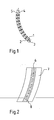
- the structure of a lamella as can be used, for example, for the realization of an actuator structure according to the invention, will be explained below with reference to the schematic illustration in FIG.
- the lamella shows a first layer 1 with nanofiber bundles and a second layer 2, the is substantially parallel to the first layer 1 and also has nanofiber bundles.
- the two layers 1 and 2 consist of a polymer in which the nanofiber bundles are embedded.
- the nanofibers can also be arranged disorderly in a felt-like, pressed structure.
- Between the two layers 1 and 2 extends an electrical insulating layer 3.
- the two layers 1 and 2 have the electrical connections 4 and 5, which are connected to a DC voltage source.
- the nanofiber bundles When a direct electrical voltage is applied to the two layers 1 and 2 as shown in the figure, the nanofiber bundles receive charge carriers or ions in one layer. As a result of the uptake or release of charge carriers, an expansion or contraction of the nanofiber bundles involved is connected, as a result the lamella shows a bend when a voltage is applied.
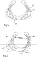
- Fig. 2 shows a single-layer realization of the integration of the lamellae in the tire material, wherein the orientation of the individual lamellae is adapted to the tire mold.
- the lamellae can be embedded in an additional layer of a material different from the tire material.
- Fig. 3 a multi-layer configuration of the slats is shown, wherein the slats are arranged partially overlapping. In this way, the lamellae can be arranged in such a way that the number of layers in the areas of the tire in which increased forces occur or are required, is adjusted accordingly. This may be necessary in particular in the region of the bead and the tread.
- the slats are integrated in an additional layer; It may also be advantageous to integrate the lamellae directly into the material of the blanket or the carcass of the tire.
- electrical connection elements in the tire are necessary.
- the actuators may be electrically contacted by metal tracks or nets introduced into the tire.
- a particularly advantageous embodiment of the invention is that the shape of the vehicle tire can be selected.
- vehicle tires are exposed to different requirements depending on the current driving situation.
- an improved rolling behavior of the tire is achieved, which effectively reduces friction and thus reduces fuel consumption.
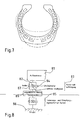
- FIG. 4 shows a vehicle tire according to the invention, in which the tire cross-section has been adapted for rapid straight-ahead driving (dotted). The change in cross-section is achieved by the lamellae 41 being stretched near the tread 42 and the louvers 43 flexing near the bead region.
- FIG. 5 shows the corresponding tire cross section.
- FIG. 6 shows the tire cross-section formed using the actuators for this driving situation. Due to the curvature of the lamellae 61 and 65 with simultaneous stretching of the lamellae 64 and 63, the vehicle tire assumes the desired shape.
- the elasticity of the vehicle tire can be made selectable. For example, it can be achieved by the actuators that the vehicle tire is set harder in the case of increased payload or bumps off road bumps. This is achieved in conventional vehicle tires so far about an increase in air pressure, which requires a certain effort. Likewise, the elasticity of conventional vehicle tires depends to a great extent on the outside temperature or the tire temperature. The invention offers here a simple solution for the optimal choice of the elasticity of the tire for the prevailing conditions. Furthermore, the described functionality can be used in case of a pressure loss in the tire To realize emergency running properties by a corresponding stiffening of the tire using the actuators. In addition, the adaptive tire deformation can be used to dampen vertical vibrations on uneven road surfaces.
- FIG. 7 This application of the vehicle tire according to the invention is illustrated in FIG. 7.
- an active part of the chassis of the vehicle tire can be set in vibrations between the two dotted and dashed maximum deflections shown.
- this leads to an effective damping of the above-mentioned vertical vibrations and thus a significantly increased ride comfort.
- the control unit may be integrated in the tires or located outside the tire.
- the sensor data can be obtained from a wide variety of sensors.
- sensors can be integrated directly into the tire material. These may be, for example, sensors based on the piezoelectric effect, which are particularly suitable for detecting deformations such as, for example, strains or compressions in the tire material.
- optical fiber sensors can be used for the said application because of their good integrability in composite materials.
- the control device determines which voltage is applied to the actuators in which region of the vehicle tire and in this way dynamically optimizes the mechanical behavior of the vehicle tire.
- sensor data can be used, which are obtained from already existing in the vehicle sensors such as speed sensors or yaw rate sensors.
- the evaluation of the sensor data and the possible dynamic Control of the characteristics of the vehicle tire according to the invention thus provides the unique possibility of further developing the last passive component of the chassis, namely the tire, into an actively controllable functional unit in the chassis system.
- the resulting fully active chassis is to be illustrated below with reference to the schematic representation of Figure 8.
- the body tree 81 ie, the vehicle itself, is in contact with the road surface 86 via the active suspension spring-damper system and the tire.
- the active chassis shows a spring 87, a shock absorber 84 and an active actuator 82, which are connected to the undamped mass of the front axle 87.
- the vehicle tire according to the invention shows active actuators, which are formed by the actuators. This leads to completely new design options in the field of driving dynamics and thus on the one hand to an increase in driving pleasure and on the other hand to further improve road safety and lower fuel consumption.
Landscapes
- Engineering & Computer Science (AREA)
- Mechanical Engineering (AREA)
- Chemical & Material Sciences (AREA)
- Nanotechnology (AREA)
- Physics & Mathematics (AREA)
- Composite Materials (AREA)
- Condensed Matter Physics & Semiconductors (AREA)
- General Physics & Mathematics (AREA)
- Materials Engineering (AREA)
- Crystallography & Structural Chemistry (AREA)
- Tires In General (AREA)
Claims (12)
- Pneumatique pour véhicule possédant des propriétés mécaniques sélectionnables, le pneumatique pour véhicule étant muni d'un ou de plusieurs actionneurs pour modifier les propriétés physiques du pneumatique pour véhicule, caractérisé en ce que les actionneurs présentent des particules à nanostructures.
- Pneumatique pour véhicule selon la revendication 1, caractérisé en ce que les actionneurs sont réalisés sous la forme de membranes.
- Pneumatique pour véhicule selon la revendication 1, caractérisé en ce que les particules à nanostructures sont des particules à nanostructures en carbone.
- Pneumatique pour véhicule selon la revendication 1 ou 3, caractérisé en ce que les particules à nanostructures sont des fibres.
- Pneumatique pour véhicule selon la revendication 4, caractérisé en ce que les fibres sont au moins partiellement des nanotubes.
- Pneumatique pour véhicule selon l'une des revendications 4 ou 5, caractérisé en ce que les fibres sont au moins partiellement des fibres de nanotubes à parois multiples.
- Pneumatique pour véhicule selon l'une des revendications précédentes, caractérisé en ce que les actionneurs sont intégrés dans le matériau du pneumatique pour véhicule.
- Pneumatique pour véhicule selon l'une des revendications précédentes 1 à 6, caractérisé en ce que les actionneurs sont intégrés dans un matériau différent du matériau du pneumatique pour véhicule.
- Pneumatique pour véhicule selon l'une des revendications précédentes, caractérisé en ce que les actionneurs sont disposés en couches dans une structure à lamelles.
- Pneumatique pour véhicule selon l'une des revendications précédentes, caractérisé en ce que la forme du pneumatique pour véhicule est sélectionnable.
- Pneumatique pour véhicule selon l'une des revendications précédentes, caractérisé en ce que l'élasticité du pneumatique pour véhicule est sélectionnable.
- Pneumatique pour véhicule selon l'une des revendications précédentes, caractérisé en ce que les actionneurs sont reliés avec une unité de commande, notamment intégrée dans le pneumatique, qui commande les actionneurs au moyen de données de capteur ou de saisie d'utilisateur.
Applications Claiming Priority (2)
| Application Number | Priority Date | Filing Date | Title |
|---|---|---|---|
| DE2003152339 DE10352339B4 (de) | 2003-11-06 | 2003-11-06 | Adaptiver-Fahrzeugreifen |
| DE10352339 | 2003-11-06 |
Publications (2)
| Publication Number | Publication Date |
|---|---|
| EP1529657A1 EP1529657A1 (fr) | 2005-05-11 |
| EP1529657B1 true EP1529657B1 (fr) | 2006-08-16 |
Family
ID=34428639
Family Applications (1)
| Application Number | Title | Priority Date | Filing Date |
|---|---|---|---|
| EP20040025986 Expired - Lifetime EP1529657B1 (fr) | 2003-11-06 | 2004-11-02 | Pneumatique adapaté comprendre des nanostructures |
Country Status (2)
| Country | Link |
|---|---|
| EP (1) | EP1529657B1 (fr) |
| DE (2) | DE10352339B4 (fr) |
Cited By (1)
| Publication number | Priority date | Publication date | Assignee | Title |
|---|---|---|---|---|
| DE102007056689A1 (de) | 2007-11-24 | 2009-05-28 | Continental Aktiengesellschaft | Fahrzeugluftreifen |
Families Citing this family (3)
| Publication number | Priority date | Publication date | Assignee | Title |
|---|---|---|---|---|
| US20090314407A1 (en) * | 2008-06-24 | 2009-12-24 | Gm Global Technology Operations, Inc. | Reducing tire rolling resistance through pre-heating |
| US20110024010A1 (en) * | 2009-07-31 | 2011-02-03 | Gm Global Technology Operations, Inc. | Performance adaptive tires utilizing active material actuation |
| JP7456286B2 (ja) | 2020-05-26 | 2024-03-27 | 住友ゴム工業株式会社 | トレッド可変装置、空気入りタイヤ、及びグリップ力制御方法 |
Family Cites Families (6)
| Publication number | Priority date | Publication date | Assignee | Title |
|---|---|---|---|---|
| US5411070A (en) * | 1990-04-05 | 1995-05-02 | Yadegar; Iraj | Self-contained anti-skid device for pneumatic tires |
| DE69904632T2 (de) * | 1998-10-28 | 2003-10-02 | Pirelli Pneumatici S.P.A., Milano | Wulstkern für luftreifen und luftreifen mit diesem kern |
| DE10001348A1 (de) * | 2000-01-14 | 2001-07-19 | Paul Horlacher | Elektromechanische Reifendruckregelanlage |
| DE10044074A1 (de) * | 2000-09-05 | 2002-03-14 | Josef W Eckel | Vorrichtung zum Verringern des Rollwiderstandes bei Autoreifen |
| DE10050595A1 (de) * | 2000-10-12 | 2002-04-18 | Oskar Bschorr | Aktoren zur Neutralisation profilbedingter Reifenschwingungen |
| DE10122812A1 (de) * | 2001-05-10 | 2002-11-28 | Continental Ag | Fahrzeugluftreifen |
-
2003
- 2003-11-06 DE DE2003152339 patent/DE10352339B4/de not_active Expired - Fee Related
-
2004
- 2004-11-02 DE DE200450001189 patent/DE502004001189D1/de not_active Expired - Lifetime
- 2004-11-02 EP EP20040025986 patent/EP1529657B1/fr not_active Expired - Lifetime
Cited By (1)
| Publication number | Priority date | Publication date | Assignee | Title |
|---|---|---|---|---|
| DE102007056689A1 (de) | 2007-11-24 | 2009-05-28 | Continental Aktiengesellschaft | Fahrzeugluftreifen |
Also Published As
| Publication number | Publication date |
|---|---|
| EP1529657A1 (fr) | 2005-05-11 |
| DE10352339B4 (de) | 2007-03-15 |
| DE502004001189D1 (de) | 2006-09-28 |
| DE10352339A1 (de) | 2005-06-23 |
Similar Documents
| Publication | Publication Date | Title |
|---|---|---|
| DE60127109T2 (de) | Piezoelektrischer generator für sensoren in fahrzeugreifen | |
| EP1417108B1 (fr) | Procede pour influer sur la tenue au roulis d'automobiles | |
| DE102014218760A1 (de) | Suspension system | |
| DE102010056388A1 (de) | Fahrzeug mit einem Blattfederelement zur Federung des Fahrzeugs | |
| EP3487718B1 (fr) | Système de ressort et d'amortissement destiné à une motocyclette | |
| DE3734287A1 (de) | Fahrzeugfahr- bzw. -laufwerk | |
| DE102020118706B4 (de) | Verfahren zur Prüfung der Eignung einer Solltrajektorie für eine Trajektorienregelung eines Fahrzeugs | |
| DE102007034840A1 (de) | Fahrwerkssystem für ein Kraftfahrzeug und Verfahren zur Fahrdynamikregelung | |
| DE102011104071A1 (de) | Blattfeder und Verfahren zu deren Herstellung | |
| WO2006117344A1 (fr) | Dispositif de direction, conçu en particulier pour une direction de roue arriere | |
| DE10202114A1 (de) | Verbundstoff-Bogen-Einblattfeder | |
| EP1529657B1 (fr) | Pneumatique adapaté comprendre des nanostructures | |
| EP1577125A2 (fr) | Système de ressorts possédant une caractéristique de ressort variable pour un véhicule avec au moins un élément de ressort principal et au moins un élément d'amortissement | |
| DE102019126045A1 (de) | Anfahrhilfe für ein Kraftfahrzeug | |
| DE102009052168A1 (de) | Intelligenter Reifen mit adaptiver Lauffläche | |
| DE102008028077A1 (de) | Vorrichtung zur aktiven Beeinflussung der Radstellung der Hinterräder eines Fahrzeugs | |
| DE10314251A1 (de) | Fahrwerkregelung | |
| DE102015225824A1 (de) | Querblattfedersystem | |
| WO2022084535A1 (fr) | Dispositif de ressort à lames, ressort à lames et ensemble amortisseur | |
| DE102008054210A1 (de) | Reifen für ein Kraftfahrzeugrad | |
| DE10123381A1 (de) | Zweirad mit aktiven Feder-/Dämpferelementen | |
| DE102016221306A1 (de) | Verstellbare Radaufhängung | |
| DE10352338A1 (de) | Fahrzeugteil mit Aktuator | |
| DE202006016061U1 (de) | Achsaufhängung mit zwei Radführungsfedern | |
| DE102015006619A1 (de) | Aus einem hybriden Werkstoffverbund bestehendes Achsbauteil in Verbindung mit einem Straßenfahrzeug oder einem Straßenfahrzeug oder einem mobilen Arbeitsgerät |
Legal Events
| Date | Code | Title | Description |
|---|---|---|---|
| PUAI | Public reference made under article 153(3) epc to a published international application that has entered the european phase |
Free format text: ORIGINAL CODE: 0009012 |
|
| AK | Designated contracting states |
Kind code of ref document: A1 Designated state(s): AT BE BG CH CY CZ DE DK EE ES FI FR GB GR HU IE IS IT LI LU MC NL PL PT RO SE SI SK TR |
|
| AX | Request for extension of the european patent |
Extension state: AL HR LT LV MK YU |
|
| 17P | Request for examination filed |
Effective date: 20051031 |
|
| AKX | Designation fees paid |
Designated state(s): DE |
|
| GRAP | Despatch of communication of intention to grant a patent |
Free format text: ORIGINAL CODE: EPIDOSNIGR1 |
|
| GRAS | Grant fee paid |
Free format text: ORIGINAL CODE: EPIDOSNIGR3 |
|
| GRAA | (expected) grant |
Free format text: ORIGINAL CODE: 0009210 |
|
| AK | Designated contracting states |
Kind code of ref document: B1 Designated state(s): DE |
|
| REF | Corresponds to: |
Ref document number: 502004001189 Country of ref document: DE Date of ref document: 20060928 Kind code of ref document: P |
|
| RAP2 | Party data changed (patent owner data changed or rights of a patent transferred) |
Owner name: DAIMLERCHRYSLER AG |
|
| PLBE | No opposition filed within time limit |
Free format text: ORIGINAL CODE: 0009261 |
|
| STAA | Information on the status of an ep patent application or granted ep patent |
Free format text: STATUS: NO OPPOSITION FILED WITHIN TIME LIMIT |
|
| 26N | No opposition filed |
Effective date: 20070518 |
|
| PGFP | Annual fee paid to national office [announced via postgrant information from national office to epo] |
Ref country code: DE Payment date: 20150129 Year of fee payment: 11 |
|
| REG | Reference to a national code |
Ref country code: DE Ref legal event code: R119 Ref document number: 502004001189 Country of ref document: DE |
|
| PG25 | Lapsed in a contracting state [announced via postgrant information from national office to epo] |
Ref country code: DE Free format text: LAPSE BECAUSE OF NON-PAYMENT OF DUE FEES Effective date: 20160601 |