EP1529503A2 - Sachet à jeter par W.C. et procédé de disposition de celui-ci - Google Patents
Sachet à jeter par W.C. et procédé de disposition de celui-ci Download PDFInfo
- Publication number
- EP1529503A2 EP1529503A2 EP05003252A EP05003252A EP1529503A2 EP 1529503 A2 EP1529503 A2 EP 1529503A2 EP 05003252 A EP05003252 A EP 05003252A EP 05003252 A EP05003252 A EP 05003252A EP 1529503 A2 EP1529503 A2 EP 1529503A2
- Authority
- EP
- European Patent Office
- Prior art keywords
- pouch
- wall
- away
- pull
- weld
- Prior art date
- Legal status (The legal status is an assumption and is not a legal conclusion. Google has not performed a legal analysis and makes no representation as to the accuracy of the status listed.)
- Granted
Links
Images


Classifications
-
- A—HUMAN NECESSITIES
- A61—MEDICAL OR VETERINARY SCIENCE; HYGIENE
- A61F—FILTERS IMPLANTABLE INTO BLOOD VESSELS; PROSTHESES; DEVICES PROVIDING PATENCY TO, OR PREVENTING COLLAPSING OF, TUBULAR STRUCTURES OF THE BODY, e.g. STENTS; ORTHOPAEDIC, NURSING OR CONTRACEPTIVE DEVICES; FOMENTATION; TREATMENT OR PROTECTION OF EYES OR EARS; BANDAGES, DRESSINGS OR ABSORBENT PADS; FIRST-AID KITS
- A61F5/00—Orthopaedic methods or devices for non-surgical treatment of bones or joints; Nursing devices; Anti-rape devices
- A61F5/44—Devices worn by the patient for reception of urine, faeces, catamenial or other discharge; Portable urination aids; Colostomy devices
- A61F5/441—Devices worn by the patient for reception of urine, faeces, catamenial or other discharge; Portable urination aids; Colostomy devices having venting or deodorant means, e.g. filters ; having antiseptic means, e.g. bacterial barriers
-
- A—HUMAN NECESSITIES
- A61—MEDICAL OR VETERINARY SCIENCE; HYGIENE
- A61F—FILTERS IMPLANTABLE INTO BLOOD VESSELS; PROSTHESES; DEVICES PROVIDING PATENCY TO, OR PREVENTING COLLAPSING OF, TUBULAR STRUCTURES OF THE BODY, e.g. STENTS; ORTHOPAEDIC, NURSING OR CONTRACEPTIVE DEVICES; FOMENTATION; TREATMENT OR PROTECTION OF EYES OR EARS; BANDAGES, DRESSINGS OR ABSORBENT PADS; FIRST-AID KITS
- A61F5/00—Orthopaedic methods or devices for non-surgical treatment of bones or joints; Nursing devices; Anti-rape devices
- A61F5/44—Devices worn by the patient for reception of urine, faeces, catamenial or other discharge; Portable urination aids; Colostomy devices
- A61F5/445—Colostomy, ileostomy or urethrostomy devices
-
- A—HUMAN NECESSITIES
- A61—MEDICAL OR VETERINARY SCIENCE; HYGIENE
- A61F—FILTERS IMPLANTABLE INTO BLOOD VESSELS; PROSTHESES; DEVICES PROVIDING PATENCY TO, OR PREVENTING COLLAPSING OF, TUBULAR STRUCTURES OF THE BODY, e.g. STENTS; ORTHOPAEDIC, NURSING OR CONTRACEPTIVE DEVICES; FOMENTATION; TREATMENT OR PROTECTION OF EYES OR EARS; BANDAGES, DRESSINGS OR ABSORBENT PADS; FIRST-AID KITS
- A61F5/00—Orthopaedic methods or devices for non-surgical treatment of bones or joints; Nursing devices; Anti-rape devices
- A61F5/44—Devices worn by the patient for reception of urine, faeces, catamenial or other discharge; Portable urination aids; Colostomy devices
- A61F2005/4402—Devices worn by the patient for reception of urine, faeces, catamenial or other discharge; Portable urination aids; Colostomy devices disposable
Definitions
- This invention relates to a water-closet (WC) disposable pouch.
- the present invention has been devised bearing the above problems in mind.
- a WC-disposable pouch comprising walls of plastics material welded together along at least one edge, a first of the walls having a pull-away element secured to the exterior thereof by one or more plastics welds or bonds such that in use, the pouch wall can be torn open adjacent or along the weld or bond by pulling the element away.
- a method of disposing of a pouch for containing body wastes down a WC, a wall of the pouch having thereon a pull away element secured thereto by one or more plastics welds or bonds the method including pulling the element away to produce a tear adjacent or along the weld or bond, then placing the pouch in the WC to be flushed away.
- the invention provides a method for use in the production of a tear-open WC-disposable pouch, comprising providing a sheet of plastics material for forming at least one wall of the pouch, and welding or bonding to a face of the sheet a pull-away element such that the sheet can be torn open adjacent or along the weld or bond by pulling the element away.
- the element is of plastics material.
- these aspects of the invention can provide an extremely user-friendly technique for tearing open a pouch, to release any trapped air or other gases prior to disposal.
- the manufacturing of the pouches can also be extremely straightforward, and can avoid any need to embed filaments within the laminate structure of the wall material.
- the element e.g. a tab
- the portion of the wall material welded or bonded to the tab remains attached to the tab, thereby creating a gap between spaced-apart edges of the material wall.
- the term "bond” as used herein covers any kind of attachment of the tab or other element to the wall material through the use of an intermediate.
- the intermediate may be an adhesive, or a hot melt layer.
- the bond strength between the tab and the wall of the pouch is greater than the tear resistance of the wall material, to achieve the desired tear action on pulling away the tab.
- the bond strength is sufficient that the region of the wall bonded to the tab is torn out of the wall, and remains attached to the tab, as described above.
- the tab (or other element) is secured to the wall of the pouch by a plastics weld.
- the weld may be a heat weld or an RF weld.
- This is advantageous because the welding process is believed to create a line or region of weakness adjacent to the position of the weld. Such a line or region of weakness will be present in both the pull-away tab and the pouch wall.
- the arrangement can be engineered to ensure that the material of the pouch wall tears before the tab itself begins to tear.
- One way of achieving this is to arrange for the material of the tab to be stronger (at least in the direction of the tear) than the material of the pouch wall.
- the relatively weak material being for the pouch wall
- the relatively strong material being for the tab.
- the tab may be thicker than the pouch wall to provide a greater relative strength.
- the welding operation creates what is known as a heat affected zone (HAZ) in the material, in which the structure of the material is believed to be modified by the application of heat sufficient to fuse the material.
- HAZ heat affected zone
- the line or region of weakness is observed to extend along the periphery of the HAZ, parallel to the weld. It is believed that the weakness may result from local orientation of the polymer chains parallel to the periphery of the HAZ, which would create reduced resistance to tearing. In any event, it has been observed that the material may readily be torn on either side of the weld, the tear(s) extending in a line closely adjacent to the weld, and parallel with the line of the weld.
- a similar effect is known to occur in welded metal joints.
- a metal structure may be vulnerable to shearing in a region adjacent to, but not exactly at, the positions of the welds. This is believed to result from the creation of a HAZ in the metal structure, around the periphery of which the material seems to be weakened.
- the welding operation also involves pressing the welded materials together to achieve a good weld. This pressing action in combination with the melting of the plastics material to achieve the weld, results in material being thinned (typically by 10-30%), which also reduces the resistance to tearing.
- weld used herein is intended to cover any securing together of the materials by fusion.
- the material of the pouch wall may be non-orientated, or it may be mono-axially or bi-axially orientated.
- non-orientated plastics material is used, and the tearing open of the pouch relies on the lines of weakness created on either side of each weld line.
- the weld or bond preferably defines a flap or hatch area of the pouch wall around which the weld or bond extends or at least partially extends and, in use, tearing of the pouch wall by pulling away the tab (or other element) releases the flap or hatch area of the pouch wall from the surrounding material.
- the flap or hatch area is preferably an integral part of the pouch wall which behaves as a flap or hatch area of material when surrounding material is tom away by pulling on the pull away element.
- a large opening can be formed in the pouch wall, by tearing around the hatch or flap area.
- a hatch area would be completely torn around its periphery so that the hatch material is substantially completely separated from the remainder of the pouch wall.
- a flap area would be tom partly around its periphery leaving intact a hinge region about which the flap material is free to fold open, to create the opening.
- the pull-away tab (or other element) has a free edge by which the tab can be grasped to pull it away from the pouch.
- the free edge may then overlie a region of the pouch wall corresponding to the "hinge" region of the flap.
- the weld or bond lines define a generally V-shaped flap area of the pouch wall. More preferably, the V-shape flap extends substantially from one edge of the pouch to substantially the opposite edge.
- the invention provides a WC-disposable pouch comprising walls of plastics material welded together along at least one edge, a first of the walls having a pull-away element of plastics material welded or bonded thereto, the weld or bond defining a flap or hatch area of the pouch wall around which the weld or bond extends or at least partially extends and, in use, pulling away of the element releases the flap or hatch area of the pouch wall from the surrounding material.
- the invention provides a WC-disposable pouch comprising walls of plastics material welded together along at least one edge, a first of the walls having a flap or hatch area defined therein by a line or region of weakness extending around or partially around said area in the wall material, and the pouch further comprising a release element attached to or embedded in the wall for breaking the material along the line or region of weakness when the element is pulled, thereby to release the hatch or flap area of material from the surrounding material.
- the invention provides a WC-disposable pouch comprising walls of plastics material welded together along at least one edge, a first of the walls having a pull-away element of plastics material secured to the exterior thereof by generally linear first and second regions of plastics welds or bonds extending opposite each other in a parallel or non-parallel arrangement.
- the first and second regions correspond to opposite edges of the pull-away element.
- the first and second regions are joined together, either directly at a common intersection region, or by a third weld or bond region.
- the first and second regions form, or form part of, a continuous weld or bond (for example defining a V, U or similar shape).
- the wearer In use, once the pouch has been filled or part-filled, and the wearer wishes to dispose of it, he or she holds it over the WC and pulls the tab, thus tearing the wall of the pouch. The pouch is then simply dropped into the WC. In effect, by pulling the tab, a thin strip of pouch wall along the length of each of the two sides of the tab is torn away still attached to the tab, so making a pair of longitudinal tears in the pouch wall.
- the tab preferably extends vertically on the pouch, but may extend in any desired direction.
- a WC-disposable pouch comprising walls of plastics material welded together along at least one peripheral edge, characterised in that one of the walls is made of a linearly-oriented plastics material and has a pull-away tear strip extending in a substantially straight line from one pouch edge to an opposite pouch edge and parallel to the direction of orientation of the plastics material of the wall, whereby the pouch can be torn open.
- a method of disposing of a pouch for containing body wastes down a WC at least one wall of the pouch being made of a linearly-oriented plastics material and having embedded therein a pull-away tear strip extending substantially parallel to the direction of linear orientation of the plastics material of the wall from one pouch edge to the other, in which the pouch is disposed of by pulling end of the ear strip to effect a tear, then placing the pouch in the WC, and flushing the WC.
- both of the pouch walls may be made of a linearly-oriented plastics material.
- the direction of orientation is preferably substantially vertical, assuming the pouch is in a normal, as worn, upright position.
- a WC-disposable pouch comprising walls of plastics material welded together along at least one peripheral edge, wherein a pull-away tear strip is secured to or embedded within a first of the walls along or closely adjacent to an elongate heat affected zone (HAZ) in the wall distinct from the welded periphery.
- HAZ heat affected zone
- a method of disposing of a pouch for containing body wastes down a WC, at least one wall of the pouch having a pull-away tear strip embedded in or secured to a first wall along or closely adjacent to an elongate heat-affected zone in the wall distinct from the welded periphery the method wherein the pouch is disposed of by pulling an end of the tear strip to effect a tear, then placing the pouch in the WC, and flushing the WC.
- the pouch In use, once the pouch of any of the above aspects has been filled or part-filled, and the wearer wishes to dispose of it, he or she holds it over the WC and pulls a tab connected to the tear strip, thus slitting the wall of the pouch from one edge to the other. The pouch is then simply dropped into the WC. In effect, the pouch is "unzipped” by pulling the tear strip.
- the pouch is approximately rectangular or pear-shaped and its said one wall may but need not be linearly oriented in a vertical direction when the pouch is in its usual position when worn.
- the tear strip also preferably extends vertically, but may extend in any desired direction.
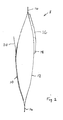
- the pouch 8 shown in Figures 1 and 2 has a front wall 10 and a rear wall 12 joined by a peripheral plastics weld 14.
- the rear wall has a stomal orifice 16 therein and a medical grade adhesive wafer 18 surrounds this orifice.
- the wafer 18 enables the pouch to be realisably attached in known manner to the peristomal skin surface of the wearer. Such wafers are known and need not be further described; the reader is referred to GB 1 044 828, GB 1 088 992 and GB 1 571 657.
- a tab 20 which may for example be a plastics strip, is attached to the outer surface of the wall 10 by a bar weld 22.
- filters are well known to those skilled in the art; other kinds of filter may be used provided they do not inhibit tearing away of the tab 20.
- the weld 22 is substantially V-shaped. It may be made by heat or RF welding.
- the plastics material of the tab is chosen to be compatible with the material of the pouch wall.
- a suitable material for the pouch wall is MF film available from W.R. Grace & Co.
- a suitable material for the tab 20 is also MF film, which may if desired be clear or a different colour from the pouch wall to aid identification.
- the weld 22 around the tab 20 defines a flap area 26 underneath the tab 20 which remains intact with the remainder of the pouch wall in normal use, thereby preserving the integrity of the pouch, but which can be released by pulling away the tab 20.
- the gaps 28 on either side of the flap area join up to form a V-shape (Fig. 4), and thereby release the flap area 26 from the surrounding material.
- the flap area 26 remains intact with the wall along the flap's uppermost edge 32, but is free to fold outwardly to allow any trapped air or other gas to escape from the pouch.
- the tears occur in the pouch wall on either side of the weld, because lines (or regions) of weakness are created on either side of the welds 22 during the welding operation.
- lines of weakness are created by a combination of a HAZ and material thinning. The lines of weakness ensure that the tears follow the welds as the tab 20 is pulled downwardly.
- the lines (or regions) of weakness will be created in the tab material as well as in the pouch material.
- the arrangement can be engineered such that the pouch material has less resistance to tearing, and will therefore always tear first before the tab begins to tear.
- the materials used for the pouch and tab may be selected such that the tab material is a stronger type of material than the pouch material.
- the pouch and tab may be made of materials of different thickness, to provide the tab with the greater strength.
- the pouch and tab are made of the same types of material (e.g. MF film), the tab material being slightly thicker than the pouch material.
- the pouch material may be of the order of 75 microns thick, and the tab material of the order of 100 microns thick.
- the flap area 26 is not fully released until after the tab 20 has been pulled fully away, and the tears in the walls of the pouch have joined at the foot of the V-shape. This ensures that, while the user's fingers are possibly close to the pouch wall (holding the tab), there is very little risk of any of the pouch contents accidentally escaping from the pouch.
- the flap is only able to fold fully open (and thus possibly allow the escape of some of the pouch contents) when the tab has been torn off, and the user's fingers will then be clear of the pouch itself.
- the provision of the flap area 26 in the opposite wall of the pouch to the stomal orifice 16 means that the gas can escape through either wall. For example, if the pouch tends to float in the WC with the front wall 10 uppermost, any gas in the pouch can escape through the opening around the flap 26. If the pouch tends to float in the WC with the rear wall 12 uppermost, gas can escape through the stomal orifice 16.
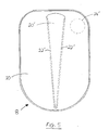
- Figure 5 shows a second example of pouch which functionally is very similar to the first example.
- the tab 20' extends substantially from the top edge of the pouch to the bottom edge, thereby defining a much larger flap area 26' in the front wall 10 of the pouch than in the first example.
- the front wall 10 When the tab 20' is pulled away, the front wall 10 will have an aperture which extends the entire length (height) of the pouch 8. This can allow the gas to escape even if the pouch is tilted at an angle in a WC. It will be appreciated that with the pouch in the first example, it may be possible for air to be trapped in a corner of the pouch if the pouch is floating at an angle with both the flap opening in the front wall 10 and the stomal orifice in the rear wall 12 below the surface of the water in the WC. Such trapped air may, in some cases still hinder flushing of the pouch down the WC waste pipe. However, by creating an aperture in at least one wall, extending from the top to the bottom of the pouch, the chances of this occurring are significantly reduced.
- the filter (if fitted) may be positioned in the pouch wall 10 to one side of the tab 20', so as not to interfere with the tab.
- the tab could be welded to one pouch wall by two parallel bar welds, one running down each side of the tab. Of course in that event the remainder of the tab would be free of attachment to the pouch wall.
- the tab may be rectangular and its width is desirably wide enough for a finger or thumb to be inserted behind it (that is, between tab and adjacent pouch wall) by the wearer of the pouch, so that the tab can be torn off so causing two tears in the pouch wall. Tearing the tab off in this way ensures that the pouch is itself sufficiently torn that it can be satisfactorily disposed of in a WC.
- the weld 22 could extend entirely around an area of the pouch wall, and thus define a hatch area in the wall. Upon pulling the tab away, the tab would tear out the entire hatch area of the wall, leaving an aperture for the escape of trapped gas. The hatch area would probably then remain attached to the tab upon removal.
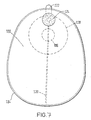
- FIG. 6 A yet further example of pouch is illustrated in Figure 6.
- the tab in the form of a longitudinal strip 40 is secured to the pouch wall 10 by a single bar weld 42 extending in a straight line from the top edge of the pouch to the bottom edge.
- the strip 40 has a free, non-welded upper end 44 by which the strip 40 can be grasped, and pulled downwardly in the same manner as the tabs of the earlier examples.
- the dotted line 48 represents the position of the strip 40 in its normal welded position.
- a tear 46 is created in the pouch wall 10.
- material 50 in the region of the weld is torn out of the pouch wall creating a gap through which any gas trapped in the pouch can escape during disposal down a WC.
- an opening is created simply by tearing out the material 50 to which the strip 40 is welded.
- the weld 42 is relatively narrow, and is not significantly wider than the welds 22 in the earlier embodiments. However, the weld 42 could be wider than that shown, and thus create a wider opening when the strip 44 is torn away.
- the width of the individual weld does not affect the pulling force which a user has to apply to tear away the tab or strip. This is because the tearing action is a result of the pouch material tearing and not destruction of the weld itself.
- the tab is completely separated from the pouch when the tab is pulled away. This provides a positive indication to the user that the tearing has been completed, and can keep the user's hands clear of the opening formed in the pouch wall in case any of the pouch contents escape before the pouch is dropped into the WC.
- the tab could also be designed to remain attached to the pouch, for example along a bottom edge, so that the tab and the pouch will always be disposed of hygienically together down the WC.
- either oriented or non-orientated plastics material may be used for the pouch and the tab.
- Orientation creates a natural weakness in the material to tearing parallel to the or a direction of orientation.
- non-orientated plastics material may provide better results. The tearing would then only occur along the lines of weakness on either side of the welds.
- orientated material may be used, with the weld 42 aligned parallel to the or a direction of orientation.
- any suitable plastics material may be used for the pouch and tab.
- the material is likely to be a laminate of different layers arranged as a film.
- the MF film referred to above is a laminate which has surface layers of an ethylene vinyl acetate (EVA) material.
- EVA ethylene vinyl acetate
- the pouch and tab have to be or include compatible material or materials for welding.
- Suitable plastics materials include (but are not limited exclusively to) polyolefins and copolymers, of which EVA is an example, and polyamides and copolymers, for example, a polyesteramide.
- Welding is a preferred method for securing the tab to the pouch wall, since welding is typically used extensively in the production of the pouch.
- the pouch is normally welded around its periphery (or part of the periphery if the pouch is formed from a single sheet). The welding of the tab to the pouch wall would typically be carried out prior to welding around the periphery, to ensure that the pouch walls are not accidentally welded together along the welds 22 or 42 in the examples.
- the pouch 108 has a front wall 110 and a rear wall 112 joined by a peripheral plastics weld 114.
- the rear wall has a stomal orifice 116 therein and an adhesive wafer 118 surrounds this orifice.
- the wafer 118 enables the pouch to be realisably attached in known manner to the peristomal skin surface of the wearer.
- a tear strip or filament 120 which may for example be a filament of polyester, is attached to the inner surface of the wall 110 and passes between the walls 110 and 112 where they are joined at the top of the pouch.
- the filament 120 has one end attached to a tab 122. It is arranged parallel to the direction of orientation of the plastics material forming the wall 110.
- a patch filter 124 e.g. of polyurethane foam or particularly charcoal cloth, or other non-woven filter substrate, and having activated carbon particles dispersed therein, is attached to an upper region of the pouch.
- filters are well known to those skilled in the art; other kinds of filter may be used provided they do not inhibit tearing away of the tear strip 120.
- a hole 126 in the pouch wall 110 permits flatus gases to reach the filter 124.
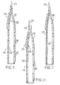
- the tab 122 is grasped and pulled with the pouch held over the WC. This completely "unzips" the wall 110 of the pouch, that is to say, a tear is made along the length of the pouch wall. The pouch can then be flushed away without difficulty.
- the embodiment of the invention shown in Figure 9 has a tear strip 130, which may be a polyester filament, embedded within the material of the wall 110.
- the tear strip 130 extends beyond the wall 110 and has a grip tab 132 attached at its upper end. When the tab 132 of the filament 130 is pulled (towards the left and downwardly as seen in Figure 3) the filament is stripped out of the wall 110. This weakens the wall to such an extent that a vertical tear or split in the wall 110 occurs.
- FIG. 10 A further embodiment of the invention is shown in Figure 10, in which a tear strip 136 is located on the outside surface of the wall 110 and passes under the filter 124.
- the tear strip 136 is welded through to the area denoted 138 of the pouch, prior to attachment of the filter 124.
- the filter may be attached to the wall 110 with adhesive.
- a tab 140 enables a protruding part of the filament to be gripped by finger and thumb. As the filament is stripped away, a section of the pouch wall 110 is in effect torn in half, and the tear is propagated along the major portion of the pouch wall. The pouch may then be disposed of down a WC without difficulty.
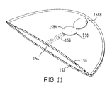
- FIG. 11 an isometric view, partly cut away, of an upper part of a WC-disposable pouch according to a further embodiment of the invention is shown.
- the pouch has a front wall 150 and a rear wall 152 and has a linear heat-affected zone 154 extending linearly along the length of the pouch.
- a polyester filament 156 is attached to the outer surface of the wall 150 e.g. by heat welding or adhesive, and has one end securely attached to a deodorizing filter 158.
- the filter 158 has a portion 158A attached to the pouch wall and a portion 158B which is free of the pouch wall.
- the pouch wall 150 has one or more holes therein adjacent to the filter so that flatus gases can exit the pouch via the filter 158. It is preferable that the filament should run parallel to the direction of the HAZ. The filament should run along or closely adjacent to the HAZ. In use, by gripping and lifting and pulling the filter tab 158B the filament 156 may be stripped out of the wall 150 leaving a substantial tear therein. Once torn in this way, the pouch may be disposed of down a WC without difficulty.
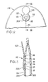
- Figures 12 and 13 further detail is given of one preferred arrangement whose basic features are similar to Figure 11.
- Figure 12 shows the front view of an upper portion of a pouch 160 to which is attached a "figure of 8" shaped filter 162.
- the pouch has walls 160A, 160B.
- Figure 13 is a cross section on the plane VII-VII of Figure 12 showing the filter portion 162A and the tab portion 162B of the filter 162, which preferably is die cut from carbon cloth type filter media.
- a hole 165 in the pouch wall 160A permits flatus gases to reach the filter 162.
- a tear filament 164 (preferably a polyester filament) is joined e.g. by an annular ring weld 166 to the filter portion 162A.
- An annular intermittent ring weld 168 is located roughly concentric with, and to surround, the weld 166. At 169, there is seen a unitary joint at which an end of the filament is attached, e.g. by welding to the filter portion 162A.
- the user holds the upper portion of the pouch 160 with one hand, and grips the tab 162B with finger and thumb of the other hand.
- the tab 162B is pulled downwardly firmly, which destroys the annular ring weld where it is attached to the pouch wall and also breaks the intermittent weld 168; however the joint of the filter part 162A to the filament 164 is made sufficiently strong that this connection is not broken.
- the pouch can then be readily disposed of down a WC.
- the filament 164 may be attached to an external surface of the pouch wall 160A or may be embedded in said wall.
- the pouch filter As mentioned, it is preferred to manufacture the pouch filter as a "figure of 8", but only weld one of the two circular parts to the pouch film with the remaining half of the '8' forming the basis of the tab, i.e. half of the filter material is effectively redundant from the filtering point of view but creates the tab to enable tear initiation.
- the filament is securely bonded to the filter area and will tear away with the filter once this process has been initiated.
- the tab could be secured to the pouch wall by two strips of strongly adhesive material, in which event the tab would be made of a material having a tensile strength greater than that of the pouch wall.
Landscapes
- Health & Medical Sciences (AREA)
- Epidemiology (AREA)
- Nursing (AREA)
- Orthopedic Medicine & Surgery (AREA)
- Engineering & Computer Science (AREA)
- Biomedical Technology (AREA)
- Heart & Thoracic Surgery (AREA)
- Vascular Medicine (AREA)
- Life Sciences & Earth Sciences (AREA)
- Animal Behavior & Ethology (AREA)
- General Health & Medical Sciences (AREA)
- Public Health (AREA)
- Veterinary Medicine (AREA)
- Orthopedics, Nursing, And Contraception (AREA)
- Bag Frames (AREA)
- Gloves (AREA)
Applications Claiming Priority (5)
| Application Number | Priority Date | Filing Date | Title |
|---|---|---|---|
| GB9613360 | 1996-06-26 | ||
| GB9613360A GB2301777B (en) | 1996-06-26 | 1996-06-26 | A water-closet-disposable pouch |
| GB9701485 | 1997-01-24 | ||
| GB9701485A GB2313061B (en) | 1997-01-24 | 1997-01-24 | Water-closet disposable pouch and method of disposal |
| EP97304522A EP0815812B2 (fr) | 1996-06-26 | 1997-06-25 | Sachet à jeter par W.C. et procédé de disposition de celui-ci |
Related Parent Applications (2)
| Application Number | Title | Priority Date | Filing Date |
|---|---|---|---|
| EP97304522A Division EP0815812B2 (fr) | 1996-06-26 | 1997-06-25 | Sachet à jeter par W.C. et procédé de disposition de celui-ci |
| EP97304522.2 Division | 1997-06-25 |
Publications (3)
| Publication Number | Publication Date |
|---|---|
| EP1529503A2 true EP1529503A2 (fr) | 2005-05-11 |
| EP1529503A3 EP1529503A3 (fr) | 2005-06-01 |
| EP1529503B1 EP1529503B1 (fr) | 2011-10-05 |
Family
ID=26309569
Family Applications (2)
| Application Number | Title | Priority Date | Filing Date |
|---|---|---|---|
| EP05003252A Expired - Lifetime EP1529503B1 (fr) | 1996-06-26 | 1997-06-25 | Sachet d'Ostomie à jeter par WC |
| EP97304522A Expired - Lifetime EP0815812B2 (fr) | 1996-06-26 | 1997-06-25 | Sachet à jeter par W.C. et procédé de disposition de celui-ci |
Family Applications After (1)
| Application Number | Title | Priority Date | Filing Date |
|---|---|---|---|
| EP97304522A Expired - Lifetime EP0815812B2 (fr) | 1996-06-26 | 1997-06-25 | Sachet à jeter par W.C. et procédé de disposition de celui-ci |
Country Status (8)
| Country | Link |
|---|---|
| US (1) | US5976118A (fr) |
| EP (2) | EP1529503B1 (fr) |
| AU (1) | AU713542B2 (fr) |
| CA (1) | CA2209201C (fr) |
| DE (1) | DE69732990T3 (fr) |
| DK (2) | DK1529503T3 (fr) |
| ES (1) | ES2242208T3 (fr) |
| GB (1) | GB2314509B (fr) |
Families Citing this family (22)
| Publication number | Priority date | Publication date | Assignee | Title |
|---|---|---|---|---|
| US6250838B1 (en) * | 1997-08-12 | 2001-06-26 | L & P Property Management Company | Garment rack locking device |
| GB2340398C (en) * | 1998-08-13 | 2007-03-16 | Bristol Myers Squibb Co | Improvements relating to ostomy pouches |
| GB9904125D0 (en) * | 1999-02-23 | 1999-04-14 | Seton Scholl Healthcare Plc | Incontinence care |
| ES2229998T5 (es) * | 1999-07-13 | 2011-01-27 | Bristol-Myers Squibb Company | Bolsa para recoger materia excretada por el cuerpo. |
| DK174796B1 (da) * | 2001-05-10 | 2003-11-24 | Coloplast As | Opsamlingspose med en udluftningsåbning |
| US6926701B2 (en) * | 2002-07-01 | 2005-08-09 | The Proctor & Gamble Company | Disposable excreta management device |
| GB0319139D0 (en) * | 2003-08-14 | 2003-09-17 | T G Eakin Ltd | Ostomy/fistula bag |
| US20050177119A1 (en) * | 2004-01-21 | 2005-08-11 | Tsai M. L. | Pouch for medical use |
| US20070010791A1 (en) * | 2005-07-07 | 2007-01-11 | Bristol-Myers Squibb Company | Valve for inflatable chamber of medical device |
| JP5119319B2 (ja) * | 2007-04-09 | 2013-01-16 | コンバテック・テクノロジーズ・インコーポレイテッド | ストーマパウチ装具 |
| US20100018724A1 (en) | 2008-07-28 | 2010-01-28 | Cleary William W | Precision Container Aerial Delivery System |
| US9138604B2 (en) | 2008-07-28 | 2015-09-22 | The Boeing Company | Aerial delivery system |
| BRPI0919631A2 (pt) | 2008-11-19 | 2015-12-01 | Convatec Technologies Inc | utensílio de bolsa de ostomia |
| RU2525209C2 (ru) * | 2008-11-19 | 2014-08-10 | Конватек Текнолоджиз Инк. | Стомное приспособление с формуемым адгезивом |
| EP2229924A1 (fr) * | 2009-03-17 | 2010-09-22 | Hollister Incorporated | Poche de stomie vidable |
| US9999536B2 (en) * | 2010-12-27 | 2018-06-19 | Benson Turtleneck Barrier Llc | Ostomy barrier seal |
| EP2922508B1 (fr) | 2012-11-20 | 2021-03-24 | ConvaTec Technologies Inc. | Sac de stomie en une pièce |
| US20140371699A1 (en) * | 2013-06-13 | 2014-12-18 | Julie Feingold | Closed ostomy bag system |
| HUE059980T2 (hu) | 2013-07-23 | 2023-01-28 | Convatec Technologies Inc | Alakítható tapadótárcsa |
| WO2015048446A1 (fr) * | 2013-09-26 | 2015-04-02 | 3 West C, Llc | Sac de stomie |
| AU2018368738B2 (en) | 2017-11-17 | 2024-04-18 | Hollister Incorporated | Receptacles having tear-controlling features |
| EP4308051A1 (fr) * | 2021-03-18 | 2024-01-24 | Hollister Incorporated | Filtre de stomie |
Citations (5)
| Publication number | Priority date | Publication date | Assignee | Title |
|---|---|---|---|---|
| EP0010171B1 (fr) | 1978-09-21 | 1981-08-26 | Intermedicat GmbH | Feuille multicouche désintégrable en milieu aqueux, et récipient et sac fabriqués à partir de cette feuille |
| GB2083762B (en) | 1980-08-12 | 1985-02-20 | Enak Ltd | Wc disposable sheet material and containers made therefrom |
| EP0272816A2 (fr) | 1986-12-22 | 1988-06-29 | E.R. Squibb & Sons, Inc. | Poche d'ostomie adaptée spécialement pour une élimination par chasse d'eau, procédé de fabrication et méthode d'élimination d'une telle poche d'ostomie |
| GB2227668A (en) | 1989-02-06 | 1990-08-08 | Squibb & Sons Inc | Flushable ostomy and faecal incontinence pouches |
| GB2227937A (en) | 1989-02-06 | 1990-08-15 | Squibb & Sons Inc | Flushable ostomy or faecal incontinence bags |
Family Cites Families (4)
| Publication number | Priority date | Publication date | Assignee | Title |
|---|---|---|---|---|
| US4838429A (en) † | 1986-10-10 | 1989-06-13 | Baxter International Inc. | Flexible thermoplastic pouches having easy-open tear strip means and apparatus for making same |
| US4930942A (en) * | 1986-12-22 | 1990-06-05 | E. R. Squibb & Sons, Inc. | Method of disposal of articles by flushing |
| US5167650A (en) * | 1989-06-16 | 1992-12-01 | E. R. Squibb | Pouch with mounting member for removable adhesive filter |
| GB2301777B (en) * | 1996-06-26 | 1997-04-30 | Bristol Myers Squibb Co | A water-closet-disposable pouch |
-
1997
- 1997-06-23 US US08/881,006 patent/US5976118A/en not_active Expired - Lifetime
- 1997-06-25 DE DE69732990T patent/DE69732990T3/de not_active Expired - Lifetime
- 1997-06-25 ES ES97304522T patent/ES2242208T3/es not_active Expired - Lifetime
- 1997-06-25 GB GB9713548A patent/GB2314509B/en not_active Expired - Fee Related
- 1997-06-25 EP EP05003252A patent/EP1529503B1/fr not_active Expired - Lifetime
- 1997-06-25 EP EP97304522A patent/EP0815812B2/fr not_active Expired - Lifetime
- 1997-06-25 DK DK05003252.3T patent/DK1529503T3/da active
- 1997-06-25 AU AU26831/97A patent/AU713542B2/en not_active Ceased
- 1997-06-25 DK DK97304522.2T patent/DK0815812T4/da active
- 1997-06-26 CA CA002209201A patent/CA2209201C/fr not_active Expired - Fee Related
Patent Citations (5)
| Publication number | Priority date | Publication date | Assignee | Title |
|---|---|---|---|---|
| EP0010171B1 (fr) | 1978-09-21 | 1981-08-26 | Intermedicat GmbH | Feuille multicouche désintégrable en milieu aqueux, et récipient et sac fabriqués à partir de cette feuille |
| GB2083762B (en) | 1980-08-12 | 1985-02-20 | Enak Ltd | Wc disposable sheet material and containers made therefrom |
| EP0272816A2 (fr) | 1986-12-22 | 1988-06-29 | E.R. Squibb & Sons, Inc. | Poche d'ostomie adaptée spécialement pour une élimination par chasse d'eau, procédé de fabrication et méthode d'élimination d'une telle poche d'ostomie |
| GB2227668A (en) | 1989-02-06 | 1990-08-08 | Squibb & Sons Inc | Flushable ostomy and faecal incontinence pouches |
| GB2227937A (en) | 1989-02-06 | 1990-08-15 | Squibb & Sons Inc | Flushable ostomy or faecal incontinence bags |
Also Published As
| Publication number | Publication date |
|---|---|
| AU713542B2 (en) | 1999-12-02 |
| EP0815812B2 (fr) | 2011-04-20 |
| GB2314509A (en) | 1998-01-07 |
| EP0815812B1 (fr) | 2005-04-13 |
| AU2683197A (en) | 1998-01-15 |
| DE69732990T3 (de) | 2012-01-12 |
| DK0815812T4 (da) | 2011-07-18 |
| EP1529503A3 (fr) | 2005-06-01 |
| GB9713548D0 (en) | 1997-09-03 |
| DE69732990D1 (de) | 2005-05-19 |
| EP1529503B1 (fr) | 2011-10-05 |
| DE69732990T2 (de) | 2006-02-16 |
| US5976118A (en) | 1999-11-02 |
| GB2314509B (en) | 1998-09-02 |
| EP0815812A1 (fr) | 1998-01-07 |
| CA2209201C (fr) | 2006-04-18 |
| DK0815812T3 (da) | 2005-08-15 |
| CA2209201A1 (fr) | 1997-12-26 |
| ES2242208T3 (es) | 2005-11-01 |
| MX9704819A (es) | 1998-07-31 |
| DK1529503T3 (da) | 2011-11-14 |
Similar Documents
| Publication | Publication Date | Title |
|---|---|---|
| EP1529503B1 (fr) | Sachet d'Ostomie à jeter par WC | |
| US7931631B2 (en) | Peelable and flushable ostomy pouch and method of use | |
| EP1557145B1 (fr) | Poche à usage médical | |
| JP2007508905A6 (ja) | はぎ取り可能なおよび水で流すことができるオストミーパウチおよび使用方法 | |
| KR101162779B1 (ko) | 개봉 용이성 포장체 | |
| EP3169286B1 (fr) | Poche de stomie | |
| JP6193324B2 (ja) | 容器の開口部を閉じるためのフォイル、ならびにフォイルを作製するための方法および装置 | |
| JP2007508905A5 (fr) | ||
| US20080294129A1 (en) | Flushable Body Waste Collection Pouches, Pouch-in Pouch Appliances Using the Same, and Methods Pertaining Thereto | |
| GB2301777A (en) | W.C. disposable pouch | |
| GB2313061A (en) | Water-closet disposable pouch and method of disposal | |
| MXPA97004819A (en) | Bag for body waste, disposable, to be eliminated by the retreat and method for disposal | |
| JP4719888B2 (ja) | オストミーパウチとその製造方法、オストミー装具 | |
| JPH05319441A (ja) | 裂開式封筒及びその製造方法 | |
| JP2007185425A (ja) | オストミーパウチとその製造方法およびオストミー装具 | |
| JPH0784223B2 (ja) | 易開封性密封袋 |
Legal Events
| Date | Code | Title | Description |
|---|---|---|---|
| PUAI | Public reference made under article 153(3) epc to a published international application that has entered the european phase |
Free format text: ORIGINAL CODE: 0009012 |
|
| PUAL | Search report despatched |
Free format text: ORIGINAL CODE: 0009013 |
|
| AC | Divisional application: reference to earlier application |
Ref document number: 0815812 Country of ref document: EP Kind code of ref document: P |
|
| AK | Designated contracting states |
Kind code of ref document: A2 Designated state(s): DE DK ES FR GB IT SE |
|
| AK | Designated contracting states |
Kind code of ref document: A3 Designated state(s): DE DK ES FR GB IT SE |
|
| 17P | Request for examination filed |
Effective date: 20051004 |
|
| AKX | Designation fees paid |
Designated state(s): DE DK ES FR GB IT SE |
|
| RAP1 | Party data changed (applicant data changed or rights of an application transferred) |
Owner name: CONVATEC TECHNOLOGIES INC. |
|
| 111Z | Information provided on other rights and legal means of execution |
Free format text: DE DK ES FR GB IT SE Effective date: 20081127 |
|
| 17Q | First examination report despatched |
Effective date: 20100916 |
|
| GRAP | Despatch of communication of intention to grant a patent |
Free format text: ORIGINAL CODE: EPIDOSNIGR1 |
|
| RTI1 | Title (correction) |
Free format text: WC-FLUSHABLE OSTOMY POUCH |
|
| GRAS | Grant fee paid |
Free format text: ORIGINAL CODE: EPIDOSNIGR3 |
|
| GRAA | (expected) grant |
Free format text: ORIGINAL CODE: 0009210 |
|
| AC | Divisional application: reference to earlier application |
Ref document number: 0815812 Country of ref document: EP Kind code of ref document: P |
|
| AK | Designated contracting states |
Kind code of ref document: B1 Designated state(s): DE DK ES FR GB IT SE |
|
| REG | Reference to a national code |
Ref country code: GB Ref legal event code: FG4D |
|
| REG | Reference to a national code |
Ref country code: DK Ref legal event code: T3 |
|
| REG | Reference to a national code |
Ref country code: DE Ref legal event code: R096 Ref document number: 69740307 Country of ref document: DE Effective date: 20111201 |
|
| REG | Reference to a national code |
Ref country code: ES Ref legal event code: FG2A Ref document number: 2371650 Country of ref document: ES Kind code of ref document: T3 Effective date: 20120105 |
|
| PG25 | Lapsed in a contracting state [announced via postgrant information from national office to epo] |
Ref country code: SE Free format text: LAPSE BECAUSE OF FAILURE TO SUBMIT A TRANSLATION OF THE DESCRIPTION OR TO PAY THE FEE WITHIN THE PRESCRIBED TIME-LIMIT Effective date: 20111005 |
|
| PGFP | Annual fee paid to national office [announced via postgrant information from national office to epo] |
Ref country code: DK Payment date: 20120612 Year of fee payment: 16 Ref country code: DE Payment date: 20120620 Year of fee payment: 16 |
|
| PLBE | No opposition filed within time limit |
Free format text: ORIGINAL CODE: 0009261 |
|
| STAA | Information on the status of an ep patent application or granted ep patent |
Free format text: STATUS: NO OPPOSITION FILED WITHIN TIME LIMIT |
|
| PGFP | Annual fee paid to national office [announced via postgrant information from national office to epo] |
Ref country code: GB Payment date: 20120620 Year of fee payment: 16 Ref country code: FR Payment date: 20120619 Year of fee payment: 16 |
|
| 26N | No opposition filed |
Effective date: 20120706 |
|
| REG | Reference to a national code |
Ref country code: DE Ref legal event code: R097 Ref document number: 69740307 Country of ref document: DE Effective date: 20120706 |
|
| PGFP | Annual fee paid to national office [announced via postgrant information from national office to epo] |
Ref country code: ES Payment date: 20120530 Year of fee payment: 16 |
|
| PG25 | Lapsed in a contracting state [announced via postgrant information from national office to epo] |
Ref country code: IT Free format text: LAPSE BECAUSE OF NON-PAYMENT OF DUE FEES Effective date: 20120625 |
|
| REG | Reference to a national code |
Ref country code: DK Ref legal event code: EBP Effective date: 20130630 |
|
| GBPC | Gb: european patent ceased through non-payment of renewal fee |
Effective date: 20130625 |
|
| REG | Reference to a national code |
Ref country code: DE Ref legal event code: R119 Ref document number: 69740307 Country of ref document: DE Effective date: 20140101 |
|
| REG | Reference to a national code |
Ref country code: FR Ref legal event code: ST Effective date: 20140228 |
|
| PG25 | Lapsed in a contracting state [announced via postgrant information from national office to epo] |
Ref country code: DE Free format text: LAPSE BECAUSE OF NON-PAYMENT OF DUE FEES Effective date: 20140101 Ref country code: GB Free format text: LAPSE BECAUSE OF NON-PAYMENT OF DUE FEES Effective date: 20130625 |
|
| PG25 | Lapsed in a contracting state [announced via postgrant information from national office to epo] |
Ref country code: FR Free format text: LAPSE BECAUSE OF NON-PAYMENT OF DUE FEES Effective date: 20130701 |
|
| REG | Reference to a national code |
Ref country code: ES Ref legal event code: FD2A Effective date: 20140707 |
|
| PG25 | Lapsed in a contracting state [announced via postgrant information from national office to epo] |
Ref country code: DK Free format text: LAPSE BECAUSE OF NON-PAYMENT OF DUE FEES Effective date: 20130630 |
|
| PG25 | Lapsed in a contracting state [announced via postgrant information from national office to epo] |
Ref country code: ES Free format text: LAPSE BECAUSE OF NON-PAYMENT OF DUE FEES Effective date: 20130626 |